WO2014192440A1 - スペーサ - Google Patents
スペーサ Download PDFInfo
- Publication number
- WO2014192440A1 WO2014192440A1 PCT/JP2014/060491 JP2014060491W WO2014192440A1 WO 2014192440 A1 WO2014192440 A1 WO 2014192440A1 JP 2014060491 W JP2014060491 W JP 2014060491W WO 2014192440 A1 WO2014192440 A1 WO 2014192440A1
- Authority
- WO
- WIPO (PCT)
- Prior art keywords
- frame
- groove
- spacer
- battery module
- battery
- Prior art date
Links
Images


Classifications
-
- H—ELECTRICITY
- H01—ELECTRIC ELEMENTS
- H01M—PROCESSES OR MEANS, e.g. BATTERIES, FOR THE DIRECT CONVERSION OF CHEMICAL ENERGY INTO ELECTRICAL ENERGY
- H01M50/00—Constructional details or processes of manufacture of the non-active parts of electrochemical cells other than fuel cells, e.g. hybrid cells
- H01M50/20—Mountings; Secondary casings or frames; Racks, modules or packs; Suspension devices; Shock absorbers; Transport or carrying devices; Holders
- H01M50/204—Racks, modules or packs for multiple batteries or multiple cells
- H01M50/207—Racks, modules or packs for multiple batteries or multiple cells characterised by their shape
- H01M50/213—Racks, modules or packs for multiple batteries or multiple cells characterised by their shape adapted for cells having curved cross-section, e.g. round or elliptic
-
- H—ELECTRICITY
- H01—ELECTRIC ELEMENTS
- H01M—PROCESSES OR MEANS, e.g. BATTERIES, FOR THE DIRECT CONVERSION OF CHEMICAL ENERGY INTO ELECTRICAL ENERGY
- H01M50/00—Constructional details or processes of manufacture of the non-active parts of electrochemical cells other than fuel cells, e.g. hybrid cells
- H01M50/20—Mountings; Secondary casings or frames; Racks, modules or packs; Suspension devices; Shock absorbers; Transport or carrying devices; Holders
- H01M50/289—Mountings; Secondary casings or frames; Racks, modules or packs; Suspension devices; Shock absorbers; Transport or carrying devices; Holders characterised by spacing elements or positioning means within frames, racks or packs
- H01M50/291—Mountings; Secondary casings or frames; Racks, modules or packs; Suspension devices; Shock absorbers; Transport or carrying devices; Holders characterised by spacing elements or positioning means within frames, racks or packs characterised by their shape
-
- H—ELECTRICITY
- H01—ELECTRIC ELEMENTS
- H01M—PROCESSES OR MEANS, e.g. BATTERIES, FOR THE DIRECT CONVERSION OF CHEMICAL ENERGY INTO ELECTRICAL ENERGY
- H01M2220/00—Batteries for particular applications
- H01M2220/10—Batteries in stationary systems, e.g. emergency power source in plant
-
- Y—GENERAL TAGGING OF NEW TECHNOLOGICAL DEVELOPMENTS; GENERAL TAGGING OF CROSS-SECTIONAL TECHNOLOGIES SPANNING OVER SEVERAL SECTIONS OF THE IPC; TECHNICAL SUBJECTS COVERED BY FORMER USPC CROSS-REFERENCE ART COLLECTIONS [XRACs] AND DIGESTS
- Y02—TECHNOLOGIES OR APPLICATIONS FOR MITIGATION OR ADAPTATION AGAINST CLIMATE CHANGE
- Y02E—REDUCTION OF GREENHOUSE GAS [GHG] EMISSIONS, RELATED TO ENERGY GENERATION, TRANSMISSION OR DISTRIBUTION
- Y02E60/00—Enabling technologies; Technologies with a potential or indirect contribution to GHG emissions mitigation
- Y02E60/10—Energy storage using batteries
Definitions
- the present invention relates to a spacer, and more particularly to a spacer disposed between modules in an apparatus configured by stacking a plurality of modules.
- Various devices are incorporated in the electric equipment. Usually, these devices are configured by stacking a plurality of modules on each other, and are accommodated in an electric device. Since the modules described above lack stability when simply stacked, generally, a spacer is disposed between the modules.
- a battery pack device used for a backup power source.
- This battery pack device is formed by combining a plurality of battery modules that can output a predetermined voltage and capacity by connecting a large number of general-purpose batteries in parallel or in series.
- each general-purpose battery is fixed in such a manner that it is accommodated in a case or sandwiched between a pair of frames.
- Such battery modules are stacked via a spacer, for example. In this way, the battery pack device is formed (see, for example, Patent Document 1).
- the spacer between cases is screwed to the connection member, respectively.
- the number of parts is large and the number of assembly steps is increased by screwing, so that the production efficiency is low.
- the shape of the portion in contact with the spacer in the frame differs between the frame on one side and the frame on the other side.
- a spacer having a shape corresponding to each frame must be prepared. That is, since the types of parts increase, the manufacturing cost increases.
- the present invention has been made based on the above circumstances, and the object of the present invention is to provide a spacer that can reduce the number and types of parts and can reduce the number of assembly steps in the manufacture of a battery pack device. It is to provide.
- the first frame and the second frame each having a plate shape are disposed between the plate surface of the first frame and the plate surface of the second frame.
- the spacer disposed between the battery modules has a square bar shape, an upper groove provided on the upper surface thereof, and provided on the lower surface thereof.
- a lower groove portion, and the upper groove portion has a first upper groove having a shape capable of fitting a lower end edge of the first frame of the battery module positioned on the upper side, and a lower end of the second frame of the battery module positioned on the upper side.
- a second of the battery modules located Spacers are provided, characterized in that the upper edge of the frame includes a second lower groove Metropolitan of shape to be fitted.
- the spacer of the present invention includes a first upper groove, a second upper groove, a first lower groove, and a second lower groove in one member.
- first, two spacers of the present invention having the same shape are prepared.
- the lower end edge of the first frame is fitted into the first upper groove, and the upper end edge of the first frame is fitted into the first lower groove.
- the lower end edge of the second frame is fitted into the second upper groove, and the upper end edge of the second frame is fitted into the second lower groove.
- the spacer according to the present invention is a single type of spacer and can be applied to both the first frame and the second frame, and the number of parts can be reduced.
- the spacer of this invention can fit each edge of a 1st frame and a 2nd frame, it is not necessary to screw together via a connection member separately, and can reduce an assembly man-hour.
- the battery module has a positioning convex portion used for positioning to a position to be installed, and the positioning in the first upper groove, the second upper groove, the first lower groove, and the second lower groove. It is preferable that the portion corresponding to the convex portion is provided with a receiving concave portion that can receive the positioning convex portion.
- the spacer of this aspect even if the positioning convex portion is formed on the battery module, the portion corresponding to the positioning convex portion in the first upper groove, the second upper groove, the first lower groove, and the second lower groove of the spacer is provided. Since the receiving concave portion that can receive the positioning convex portion is provided, the positioning convex portion is prevented from colliding locally with the groove bottom of the upper groove or the lower groove, and the battery modules are stably stacked. As a result, the battery pack device can be easily assembled.
- the present invention it is possible to provide a spacer that can reduce the number and types of parts and can reduce the number of assembly steps in manufacturing a battery pack device.
- FIG. 5 is a sectional view taken along line VV in FIG. 4. It is the end elevation which showed the state which looked at the spacer which concerns on embodiment in the arrow D direction in FIG. It is the top view which showed the state which looked at the spacer which concerns on embodiment in the arrow E direction in FIG. It is the right view which showed the state which looked at the spacer which concerns on embodiment in the arrow F direction in FIG. It is the bottom view which showed the state which looked at the spacer which concerns on embodiment in the arrow G direction in FIG. It is the left view which showed the state which looked at the spacer which concerns on embodiment in the arrow H direction in FIG.
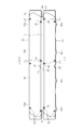
- the battery pack device 4 is formed by stacking two battery modules 6 and 6 via square bar spacers 2 and 2.
- square bar shape refers to a long bar shape having a rectangular cross section.
- the battery pack device 4 is accommodated in a storage space in the electric device.
- the accommodation space includes a floor surface having a predetermined area, a support provided at a predetermined position on the floor, and a pressing plate attached to the support.
- the battery pack device 4 is placed on the floor surface of the accommodation space, and is pressed and fixed from above by a pressing plate.
- the battery module 6 is formed by arranging a plurality of assembled batteries 8 between the first frame 10 and the second frame 12 and sandwiching them between the first frame 10 and the second frame 12. Has been.
- the assembled battery 8 is integrated by arranging two general-purpose AA-sized nickel-hydrogen secondary batteries (hereinafter referred to as unit batteries) in parallel in a set and wrapping them with an exterior film. These unit cells are arranged so that the positive electrode terminal side and the negative electrode terminal side are opposite to each other, and the negative electrode terminal of one unit cell and the positive electrode terminal of the other unit cell are electrically connected by a lead (not shown). Connected in series. And the positive electrode terminal of one unit battery and the negative electrode terminal of the other unit battery are exposed from the exterior film. Eighteen such assembled batteries 8 are prepared and are arranged so that the trunks of each battery are in contact with each other. In this way, an assembly of the assembled battery 8 is formed. At this time, each assembled battery is arranged in a state inclined in the direction of arrow A, as is apparent from FIG. These assembled batteries 8 are sandwiched and fixed between the first frame 10 and the second frame 12.
- unit batteries general-purpose AA-sized nickel-hydrogen secondary batteries
- the first frame 10 is located on the left side in FIG. 2 and is a plate-like body having a substantially rectangular shape. As is apparent from FIG. 2, the first frame 10 is provided with a plurality of pressing protrusions 16 having a substantially triangular cross section on the inner surface 14 on the assembled battery 8 side. The pressing protrusion 16 is positioned at a predetermined position between the assembled battery 8 and the portion in contact with the assembled battery 8 has a shape along a part of the outer peripheral edge of the assembled battery 8. 8 serves to suppress the vertical displacement of the battery module 6. Further, as is apparent from FIG. 2, end stoppers 18 are formed in the vicinity of both ends in the longitudinal direction of the first frame 10. The end stopper 18 is a frame having a shape matching the outer peripheral edge of the body portion of the assembled battery 8, and functions to prevent the assembled battery 8 located at the outermost end from shifting in the front-rear direction of the battery module 6. There is no.
- the second frame 12 is a plate-like body that is positioned on the right side in FIG. 2 and has a substantially parallelogram shape. Similar to the first frame 10, the second frame 12 is also provided with a pressing protrusion 16 and an end stopper 18.
- the pressing protrusion 16 of the second frame 12 has the same shape as the pressing protrusion 16 of the first frame 10, and is positioned at a position facing the pressing protrusion 16 of the first frame 10.
- the end stopper 18 of the second frame 12 has the same shape as the end stopper 18 of the first frame 10 and is positioned at a position facing the end stopper 18 of the first frame 10.
- the first frame 10 and the second frame 12 as described above are positioned to face each other so that the pressing protrusion 16 and the end stopper 18 face each other. 16 and the end stopper 18, and the pressing protrusion 16 and the end stopper 18 of the second frame 12 cooperate to position the assembled battery 8.
- the connector 20 includes a hollow cylindrical member 22 having a central through hole extending in the longitudinal direction, a bolt 24 inserted through the central through hole, and a nut 26 screwed into the bolt.
- the cylindrical member 22 is substantially the same as the length of the assembled battery 8 in the longitudinal direction, and is disposed at a position corresponding to the bolt insertion hole provided at a predetermined position of the first frame 10 and the second frame 12.
- the above-described bolt 24 is inserted from the bolt insertion hole side on the second frame 12 side into the through hole on the first frame 10 side through the center through hole of the connector 20.
- a nut 26 is screwed onto the tip of the bolt 24 protruding from the bolt insertion hole on the first frame 10 side.
- the first frame 10 and the second frame 12 are urged toward each other, and the battery modules 6 are formed by sandwiching the assembled batteries 8.
- each assembled battery 8 sandwiched between the first frame 10 and the second frame 12 and arranged at a predetermined position is a frame lead (not shown) provided on the first frame 10 or the second frame 12.
- the second frame 12 is provided with a connector cutout 28 as shown in FIG.
- a female connector (not shown) is disposed inside the connector notch 28, and the above-described frame lead (not shown) is electrically connected to the female connector.
- a male connector (not shown) is inserted into the female connector, and a lead wire (not shown) connected to the male connector is drawn out from the connector cutout 28.
- electricity is input / output through the male connector and the lead wire.
- the battery module 6 has the first frame 10 positioned on one side and the second frame 12 positioned on the other side.
- the assembly of the assembled batteries 8 is hidden by the first frame 10 and the second frame 12 (see FIGS. 3 and 4). That is, the first frame 10 and the second frame 12 protrude from the assembly of the assembled battery 8. Specifically, as shown in the cross-sectional view of FIG.
- the first frame 10 has an upper end edge (hereinafter referred to as a first upper end edge) 36 protruding above the upper end 32 of the body portion of the assembled battery 8 and a lower end edge (hereinafter referred to as a first lower end edge). 40 protrudes below the lower end 34 of the body portion of the assembled battery 8.
- the second frame 12 has an upper end edge (hereinafter referred to as a second upper end edge) 38 protruding above the upper end 32 of the body portion of the assembled battery 8 and a lower end edge (hereinafter referred to as a second lower end edge) 42. It protrudes below the lower end 34 of the body part of the assembled battery 8.
- first upper edge 36 and the second upper edge 38 are denoted by reference numerals 36a, 36b, 36c, 36d, 38a, 38b, 38c, and 38d, respectively.
- a recess is provided.
- These concave portions are provided in order to avoid convex portions provided on the pressing plate in the accommodation space.
- the first lower end edge 40 and the second lower end edge 42 are positioned as indicated by reference numerals 40a, 40b, 40c, 40d, 42a, 42b, 42c, and 42d, as is apparent from FIGS. Convex part is provided. These positioning convex portions 40a, 40b, 40c, 40d, 42a, 42b, 42c, and 42d are fitted into concave portions provided at predetermined positions on the floor surface of the storage space, and the positioning of the lowermost battery module 6, that is, The battery pack device 4 is used for positioning.
- the concave portions 36a, 36b, 36c, 36d, 38a, 38b, 38c, 38d, and the positioning convex portions 40a, 40b, 40c, 40d, 42a, 42b, 42c, 42d are formed on the first upper edge 36, The positions and sizes of the first lower edge 40, the second upper edge 38, and the second lower edge 42 are different. For this reason, when the battery modules 6 are directly stacked, the upper edge and the lower edge of the frames that are in contact with each other locally collide, making it difficult to stably stack the battery modules 6. For this reason, the spacer 2 is disposed between the battery module 6 and the battery module 6.
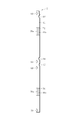
- the spacer 2 is a long rectangular bar having a rectangular cross section, and four concave grooves extending along the longitudinal direction are provided on the upper side and two on the lower side. It has been. Specifically, as is clear from the end view shown in FIG. 6, the spacer 2 includes a first upper groove 44 positioned on the left side and upper side in FIG. 6, and a second upper groove 46 positioned on the right side and upper side in FIG. 6. 6, the first lower groove 48 positioned on the left side and the lower side in FIG. 6, the second lower groove 50 positioned on the right side and the lower side in FIG. 6, and the first upper groove 44 and the first lower groove 48 on the left side in FIG. 6.
- the first side wall 41 positioned, the second side wall 43 positioned on the right side of the second upper groove 46 and the second lower groove 50 in FIG. 6, the upper partition wall 45 separating the first upper groove 44 and the second upper groove 46, And a lower partition wall 49 separating the first lower groove 48 and the second lower groove 50.
- the first upper groove 44 can fit the first lower end edge 40 of the first frame 10.
- the second upper groove 46 can fit the second lower end edge 42 of the second frame 12.
- the first lower groove 48 can fit the first upper end edge 36 of the first frame 10.
- the second lower groove 50 can fit the second upper end edge 38 of the second frame 12.
- the spacer 2 is provided with receiving recesses 52, 54, 56, 58 at predetermined positions on the upper side where the first upper groove 44 and the second upper groove 46 are provided. Yes.
- the receiving recesses 52, 54, 56, and 58 correspond to the positioning protrusions 40 a, 40 b, 40 c, and 40 d provided on the first lower end edge 40 of the first frame 10 and the second frame 12, respectively.
- the concave portions are provided at positions corresponding to the convex portions 42a, 42b, 42c, and 42d for positioning provided on the second lower end edge 42, respectively.
- the upper partition 45 is removed, and further, the portion from which the upper partition 45 is removed, and the groove bottom 44a of the first upper groove 44 and the groove bottom 46a of the second upper groove 46.
- a predetermined depth corresponding to the height of the positioning convex portions (40a, 40b, 40c, 40d, 42a, 42b, 42c, 42d) toward the back side, and dents (receiving concave portions 52, 54, 56, 58) is formed.
- These receiving recesses 52, 54, 56, and 58 are rectangular in plan view as is apparent from FIG.
- positioning convex portions 40a and 42a are provided in the receiving concave portion 52
- positioning convex portions 40b and 42b are provided in the receiving concave portion 54
- positioning convex portions 40c and 42c are provided in the receiving concave portion 56
- the receiving concave portion 58 is provided in the receiving concave portion 58.
- Positioning convex portions 40d and 42d are respectively received.
- the spacer 2 is provided with notches penetrating predetermined positions of the right side wall 43, the upper side partition 45, the lower side partition 49, and the left side wall 41.
- a semicircular semicircular notch indicated by reference numerals 60, 62, 64, 66, 68, and 70 and a rectangular rectangular notch indicated by reference numeral 72 are provided. These semicircular notches are located at positions corresponding to the bolts 24 or nuts 26 described above, and are provided to avoid the bolts 24 and nuts 26.
- the rectangular cutout 72 is positioned at a position corresponding to the connector cutout 28 described above, and is provided to avoid the connector cutout 28.
- first lower groove 48 and the second lower groove 50 extend in parallel on the lower surface side of the spacer 2, and the receiving recesses 52, 54 on the upper surface side. , 56, 58 are not provided with recesses.
- reference numeral 48 a indicates the groove bottom of the first lower groove 48
- reference numeral 50 a indicates the groove bottom of the second lower groove 50.
- side cutouts 74 and 76 are provided in the first side wall 41.
- the side cutouts 74 and 76 are formed by removing portions of the first side wall 41 corresponding to the above-mentioned support columns in the vertical direction of the spacer 2.
- Spacers 2 are used in pairs of the same shape. For example, when two battery modules 6 are stacked, as shown in FIG. 5, between the upper battery module 6 and the lower battery module 6, the first frame 10 side (left side in FIG. 5) and the second Spacers 2 and 2 are disposed on the frame 12 side (right side in FIG. 5), respectively.
- the first lower end edge 40 of the first frame 10 of the upper battery module 6 is fitted into the first upper groove 44 of the spacer 2
- the first upper end edge 36 of the first frame 10 of the lower battery module 6 is The first lower groove 48 of the spacer 2 is fitted.
- the second lower end edge 42 of the second frame 12 of the upper battery module 6 is fitted into the second upper groove 46 of the spacer 2
- the second upper end edge 38 of the second frame 12 of the lower battery module 6 is The second lower groove 50 of the spacer 2 is fitted.
- the convex portions 40a, 40b, 40c, 40d and the positioning convex portions 42a, 42b, 42c, 42d provided on the second lower end edge 46 of the second frame 12 are received, and these positioning convex portions are the groove bottoms 44a, 46a. It is possible to prevent local collisions.
- the first upper end edge 36 of the first frame 10 and the second upper end edge 38 of the second frame 12 have the recesses 36a, 36b, 36c, 36d, 38a, 38b, 38c, 38d, respectively.
- the groove bottoms 48a and 50a of the first lower groove 48 and the second lower groove 50 in the spacer 2 do not collide locally.
- the semicircular cutouts 60, 62, 64, 66, 68 and 70 provided in the spacer 2 avoid the bolt 24 and the nut 26. Thereby, the bolt 24 or the nut 24 and the spacer 2 do not collide with each other.
- the rectangular cutout 72 avoids the connector cutout 28. As a result, the rectangular cutout 72 and the connector cutout 28 communicate with each other, and it is effectively prevented from hindering the insertion / extraction of the connector or the drawing of the lead wire of the connector.
- the battery modules 6 and 6 are stacked in a stable state with the spacers 2 and 2 interposed therebetween. Thereby, the battery pack apparatus 4 is formed.
- the obtained battery pack device 4 is housed in a housing space in the electric device.
- positioning protrusions 40a, 40b, and 40c on the lower end edge 40 of the first frame 10 and the lower end edge 42 of the second frame 12 in the lower battery module 6 are provided in the positioning holes provided in the floor surface of the accommodation space.
- 40d, 42a, 42b, 42c, 42d are fitted.
- the upper battery module 6 is pressed and fixed from above by a pressing plate attached to a support provided on the floor surface. In this way, the battery pack device 4 is accommodated in the electric device.
- the spacer 2 according to the present invention is one type, and can correspond to the first lower end edge 40 and the first upper end edge 36 of the first frame 10, and the second lower end edge 42 and the second upper end edge 38 of the second frame 12.
- battery modules having different shapes on the upper side and the lower side of the frame can be easily stacked, and the number of parts can be reduced.
- the floor area of the storage space for the electric equipment can be secured larger, more battery pack devices 4 can be mounted.
- the accommodation space has a width of 450 mm, a depth of 460 mm, and a height of 93.5 mm, six battery pack devices 4 can be mounted.
- the battery modules 6 can be easily stacked in two stages, a power supply having a capacity twice as large as that in the case of one stage can be easily configured.
- the present invention is not limited to this mode.
- the spacer 2 according to the present invention can cope with the battery module 6 being laminated in two or more stages.
- Second frame First upper edge 38 Second upper edge 40 First lower edge 42 Second lower edge 40a to 40d Positioning convex portions 42a to 42d Positioning convex portion 44 First upper groove 46 Second upper groove 48 First lower groove 50 Second lower groove 52, 54, 56, 58 Receiving concave portion
Landscapes
- Chemical & Material Sciences (AREA)
- Chemical Kinetics & Catalysis (AREA)
- Electrochemistry (AREA)
- General Chemical & Material Sciences (AREA)
- Battery Mounting, Suspending (AREA)
Abstract
スペーサ2は、角棒状をなし、その上面に設けられた上溝部と、その下面に設けられた下溝部とを備え、上溝部は、上側に位置する電池モジュール6の第1フレーム10の第1下端縁40を嵌合可能な形状の第1上溝44と、上側に位置する電池モジュール6の第2フレーム12の第2下端縁42を嵌合可能な形状の第2上溝46とを含み、下溝部は、下側に位置する電池モジュール6の第1フレーム10の第1上端縁36を嵌合可能な形状の第1下溝48と、下側に位置する電池モジュール6の第2フレーム12の第2上端縁38を嵌合可能な形状の第2下溝50とを含んでいる。
Description
本発明は、スペーサに関し、詳しくは、複数のモジュールを積み重ねて構成される装置における各モジュール間に配置されるスペーサに関する。
電気機器の内部には、種々の装置が組み込まれている。通常、これらの装置は、複数のモジュールが互いに積み重ねられて構成され、電気機器内に収容されている。
上記したようなモジュールは、単純に積み重ねたのでは安定性に欠けるので、一般的に、各モジュールの間にはスペーサが配置される。
上記したようなモジュールは、単純に積み重ねたのでは安定性に欠けるので、一般的に、各モジュールの間にはスペーサが配置される。
ここで、電気機器に搭載される装置としては、例えば、バックアップ電源に使用される電池パック装置がある。この電池パック装置は、多数の汎用電池が並列又は直列に接続され所定の電圧及び容量を出力可能とした電池モジュールが、用途に合わせて複数個組み合わされることにより形成されている。この電池モジュールにおいて各汎用電池は、ケースに収容される、又は、一対のフレームの間に挟持される態様で固定されている。このような電池モジュールは、例えば、スペーサを介して積層される。このようにして電池パック装置は形成される(例えば、特許文献1参照)。
ところで、特許文献1の電池パック装置の場合、ケースとケースの間のスペーサは、それぞれ連結部材にねじ止めされている。この場合、部品点数が多く、ねじ止めにより組立工数も増えるので、生産効率が低い。
また、一対のフレームを用いる電池モジュールの場合、フレームにおけるスペーサと接する部分の形状が、一方の側のフレームと他方の側のフレームとで異なるものがある。この場合、それぞれのフレームに対応した形状のスペーサを準備しなければならない。つまり、部品の種類が増えるため、製造コストの増加を招く。
また、一対のフレームを用いる電池モジュールの場合、フレームにおけるスペーサと接する部分の形状が、一方の側のフレームと他方の側のフレームとで異なるものがある。この場合、それぞれのフレームに対応した形状のスペーサを準備しなければならない。つまり、部品の種類が増えるため、製造コストの増加を招く。
本発明は、上記の事情に基づいてなされたものであり、その目的とするところは、電池パック装置の製造において、部品の点数及び種類の低減が図れ、且つ、組み立て工数の削減も図れるスペーサを提供することにある。
上記目的を達成するために、本発明によれば、それぞれ板状をなす第1フレーム及び第2フレームと、前記第1フレームの板面及び前記第2フレームの板面の間に配設された複数の電池とを備えた電池モジュールを複数個重ねる際に、各電池モジュールの間に配設されるスペーサにおいて、角棒状をなし、その上面に設けられた上溝部と、その下面に設けられた下溝部とを備え、前記上溝部は、上側に位置する前記電池モジュールの第1フレームの下端縁を嵌合可能な形状の第1上溝と、上側に位置する前記電池モジュールの第2フレームの下端縁を嵌合可能な形状の第2上溝とを含み、前記下溝部は、下側に位置する前記電池モジュールの第1フレームの上端縁を嵌合可能な形状の第1下溝と、下側に位置する前記電池モジュールの第2フレームの上端縁を嵌合可能な形状の第2下溝とを含んでいることを特徴とするスペーサが提供される。
本発明のスペーサは、一つの部材の中に第1上溝、第2上溝、第1下溝及び第2下溝を備えている。本発明のスペーサの具体的な使い方としては、まず、同形状の本発明のスペーサを2本準備する。そして、一本のスペーサにおいては、第1フレームの下端縁を第1上溝に嵌合させ、第1フレームの上端縁を第1下溝に嵌合させる。もう一本のスペーサにおいては、第2フレームの下端縁を第2上溝に嵌合させ、第2フレームの上端縁を第2下溝に嵌合させる。このように、本発明のスペーサは、一種類のスペーサで、第1フレーム及び第2フレームの両方に対応が可能であり、部品点数を少なくすることができる。
また、本発明のスペーサは、第1フレーム及び第2フレームの各端縁を嵌合可能なので、個々に連結部材を介してねじ止めする必要がなく、組立工数を少なくすることができる。
また、本発明のスペーサは、第1フレーム及び第2フレームの各端縁を嵌合可能なので、個々に連結部材を介してねじ止めする必要がなく、組立工数を少なくすることができる。
また、前記電池モジュールは、設置されるべき位置への位置決めに用いられる位置決め用凸部を有しており、前記第1上溝、前記第2上溝、前記第1下溝及び前記第2下溝における前記位置決め用凸部に対応する部分には、前記位置決め用凸部を受入可能な受入凹部が設けられている態様とすることが好ましい。
この態様のスペーサによれば、電池モジュールに位置決め用凸部が形成されていても、スペーサの第1上溝、第2上溝、第1下溝及び第2下溝における前記位置決め用凸部に対応する部分には、この位置決め用凸部を受入可能な受入凹部が設けられているので、かかる位置決め用凸部が上溝又は下溝の溝底と局部的にぶつかりあうことは抑制され、電池モジュールを安定的に積み重ねることができ電池パック装置の組立が容易となる。
本発明によれば、電池パック装置の製造において、部品の点数及び種類の低減が図れ、且つ、組み立て工数の削減も図れるスペーサを提供することができる。
以下、本発明に係るスペーサ2を適用した電池パック装置4を、図面を参照して説明する。
図1に示したように、電池パック装置4は、2個の電池モジュール6,6が、角棒状のスペーサ2,2を介して積み重ねられて形成されている。なお、角棒状とは、横断面の形状が矩形状をなす長尺の棒状の形態をいう。
この電池パック装置4は、電気機器内の収容スペースに収容される。通常、収容スペースは、所定面積の床面と、この床面の所定位置に設けられた支柱と、この支柱に取り付けられた押さえ板を含んでいる。そして、電池パック装置4は、収容スペースの床面に載置され、押さえ板により上から押さえられて固定されている。
次いで、電池モジュール6の形態について以下に説明する。
電池モジュール6は、図2に示すように、複数の組電池8が第1フレーム10及び第2フレーム12の間に並べられ、これら第1フレーム10及び第2フレーム12に挟持されることにより形成されている。
電池モジュール6は、図2に示すように、複数の組電池8が第1フレーム10及び第2フレーム12の間に並べられ、これら第1フレーム10及び第2フレーム12に挟持されることにより形成されている。
組電池8は、汎用のAAサイズのニッケル水素二次電池(以下、単位電池という)が2個一組で並列に並べられ外装フィルムにより包み込まれることにより一体化されてなる。これら単位電池は、互いに正極端子側と負極端子側とが逆となるように並べられており、図示しないリードにより、一方の単位電池の負極端子と他方の単位電池の正極端子とが電気的に直列に接続されている。そして、一方の単位電池の正極端子及び他方の単位電池の負極端子は外装フィルムから露出している。このような組電池8は、18個準備され、互いの胴部が接するように並べられる。このようにして組電池8の集合体が形成されている。このとき、各組電池は、図2から明らかなように、矢印A方向に傾いた状態で並べられている。そして、これら組電池8は、第1フレーム10及び第2フレーム12により挟持され固定されている。
第1フレーム10は、図2において左側に位置しており、略長方形状をなす板状体である。この第1フレーム10には、図2から明らかなように、組電池8側の内面14に断面が略三角形状の押さえ突起16が複数設けられている。この押さえ突起16は、組電池8と組電池8との間の所定位置に位置付けられ、組電池8と接する部分が組電池8の外周縁の一部に沿う形状をなしており、これら組電池8が電池モジュール6の上下方向にずれることを抑える働きをなしている。更に、図2から明らかなように、第1フレーム10の長手方向の両端近傍には、端部ストッパ18が形成されている。この端部ストッパ18は、組電池8の胴部の外周縁に合致した形状をなした枠であり、最端部に位置する組電池8が電池モジュール6の前後方向にずれることを抑える働きをなしている。
ついで、第2フレーム12は、図2において右側に位置しており、略平行四辺形状をなす板状体である。この第2フレーム12にも、第1フレーム10と同様に、押さえ突起16及び端部ストッパ18が設けられている。この第2フレーム12の押さえ突起16は、第1フレーム10の押さえ突起16と同形状をなしており、第1フレーム10の押さえ突起16に対向する位置に位置付けられている。また、第2フレーム12の端部ストッパ18も、第1フレーム10の端部ストッパ18と同形状をなしており、第1フレーム10の端部ストッパ18に対向する位置に位置付けられている。
上記したような第1フレーム10及び第2フレーム12は、対向配置されることにより、お互いの押さえ突起16及び端部ストッパ18が相対する位置に位置付けられ、これにより、第1フレーム10の押さえ突起16及び端部ストッパ18と、第2フレーム12の押さえ突起16及び端部ストッパ18とは、協働して組電池8の位置決めを行う。
上記したように組電池8が所定位置に位置決めされた第1フレーム10及び第2フレーム12は、連結具20により連結されている。この連結具20は、長手方向に延びる中心貫通孔を有する中空の円筒部材22と、この中心貫通孔に挿通されたボルト24と、このボルトに螺合されたナット26とからなる。この円筒部材22は、上記した組電池8の長手方向の長さと略同じ長さであり、第1フレーム10及び第2フレーム12の所定位置に設けられたボルト挿通孔に対応する位置に配置される。上記したボルト24は、第2フレーム12側のボルト挿通孔側から、連結具20の中心貫通孔を介して第1フレーム10側の貫通孔に挿通される。そして、第1フレーム10側のボルト挿通孔から突出したボルト24の先端にはナット26が螺合されている。これにより、第1フレーム10及び第2フレーム12が互いに近付く方向に付勢され各組電池8が挟持されて電池モジュール6が形成される。
ここで、第1フレーム10及び第2フレーム12の間に挟持され、所定位置に配置されている各組電池8は、第1フレーム10又は第2フレーム12に設けられたフレームリード(図示せず)により電気的に直列に接続されている。また、第2フレーム12には、図2に示すようにコネクタ用切欠28が設けられている。このコネクタ用切欠28の部分の内部に雌コネクタ(図示せず)が配設されており、この雌コネクタには上記したフレームリード(図示せず)が電気的に接続されている。そして、この雌コネクタには、雄コネクタ(図示せず)が差し込まれ、コネクタ用切欠28からは雄コネクタに接続されたリード線(図示せず)が引き出される。電池モジュール6においては、この雄コネクタ及びリード線を介して電気の入出力が行われる。
電池モジュール6は、上記したように、一方の側部に第1フレーム10が、他方の側部に第2フレーム12がそれぞれ位置付けられている。そして、この電池モジュール6を側面視した際、組電池8の集合体は、これら第1フレーム10及び第2フレーム12に隠れている(図3、図4参照)。つまり、これら第1フレーム10及び第2フレーム12は、組電池8の集合体よりも突出している。詳しくは、図5の断面図に表されているように、組電池8の断面において、胴部30の上端を胴部上端32、胴部30の下端を胴部下端34とした場合に、第1フレーム10及び第2フレーム12の上端縁36,38は胴部上端32よりも上方へ僅かに突出し、第1フレーム10及び第2フレーム12の下端縁40,42は胴部下端34よりも下方へ僅かに突出している。より詳しくは、第1フレーム10は、その上端縁(以下、第1上端縁という)36が組電池8の胴部上端32よりも上側に突出し、その下端縁(以下、第1下端縁という)40が組電池8の胴部下端34よりも下側に突出している。また、第2フレーム12は、その上端縁(以下、第2上端縁という)38が組電池8の胴部上端32よりも上側に突出し、その下端縁(以下、第2下端縁という)42が組電池8の胴部下端34よりも下側に突出している。
ここで、第1上端縁36及び第2上端縁38は、図3、図4から明らかなように、それぞれ、参照符号36a,36b,36c,36d,38a,38b,38c,38dで示された凹部を備えている。これら凹部は、収容スペース内の押さえ板に設けられた凸部を避けるために設けられている。
また、第1下端縁40及び第2下端縁42は、図3、図4から明らかなように、それぞれ、参照符号40a,40b,40c,40d,42a,42b,42c,42dで示された位置決め用凸部を備えている。これら位置決め用凸部40a,40b,40c,40d,42a,42b,42c,42dは、収容スペースの床面の所定位置に設けられた凹部に嵌合され、最下部の電池モジュール6の位置決め、つまり、電池パック装置4の位置決めに利用される。
通常、上記した凹部36a,36b,36c,36d,38a,38b,38c,38d、及び、位置決め用凸部40a,40b,40c,40d,42a,42b,42c,42dは、第1上端縁36、第1下端縁40、第2上端縁38及び第2下端縁42によって、形成されている位置や大きさが異なる。このため、電池モジュール6を直接積み重ねると、互いに当接するフレームの上端縁と下端縁とは局部的にぶつかりあってしまい、安定的に積み重ねることは困難である。このため、電池モジュール6と電池モジュール6との間にはスペーサ2が配置されている。
スペーサ2は、図2に示すように、横断面が矩形状である長尺の角棒であり、長手方向に沿って延びる凹溝が上側に2本、下側に2本の合計4本設けられている。詳しくは、スペーサ2は、図6に示す端面図から明らかなように、図6中左側且つ上側に位置付けられた第1上溝44と、図6中右側且つ上側に位置付けられた第2上溝46と、図6中左側且つ下側に位置付けられた第1下溝48と、図6中右側且つ下側に位置付けられた第2下溝50と、第1上溝44及び第1下溝48の図6中左側に位置付けられた第1側壁41と、第2上溝46及び第2下溝50の図6中右側に位置付けられた第2側壁43と、第1上溝44及び第2上溝46を隔てる上側隔壁45と、第1下溝48及び第2下溝50を隔てる下側隔壁49とを備えている。
第1上溝44は、図5に示すように、第1フレーム10の第1下端縁40を嵌合可能である。
第2上溝46は、図5に示すように、第2フレーム12の第2下端縁42を嵌合可能である。
第1下溝48は、図5に示すように、第1フレーム10の第1上端縁36を嵌合可能である。
第2下溝50は、図5に示すように、第2フレーム12の第2上端縁38を嵌合可能である。
第2上溝46は、図5に示すように、第2フレーム12の第2下端縁42を嵌合可能である。
第1下溝48は、図5に示すように、第1フレーム10の第1上端縁36を嵌合可能である。
第2下溝50は、図5に示すように、第2フレーム12の第2上端縁38を嵌合可能である。
スペーサ2においては、図7に示す上面図から明らかなように、第1上溝44及び第2上溝46が設けられている上側の所定位置に、受入凹部52,54,56,58が設けられている。詳しくは、これら受入凹部52,54,56,58は、それぞれ対応する、第1フレーム10の第1下端縁40に設けられた位置決め用凸部40a,40b,40c,40d及び第2フレーム12の第2下端縁42に設けられた位置決め用凸部42a,42b,42c,42dにそれぞれ対応する凹部形成位置に設けられている。より詳しくは、この凹部形成位置においては、上側隔壁45が除去され、更に、この上側隔壁45が除去された部分と、第1上溝44の溝底44a及び第2上溝46の溝底46aの部分とが裏側に向かって位置決め用凸部(40a,40b,40c,40d,42a,42b,42c,42d)の高さに相当する所定深さだけ掘り下げられ、凹み(受入凹部52,54,56,58)が形成されている。これら受入凹部52,54,56,58は、図7から明らかなように平面視形状が矩形状をなしている。ここで、受入凹部52には位置決め用凸部40a,42aが、受入凹部54には位置決め用凸部40b,42bが、受入凹部56には位置決め用凸部40c,42cが、受入凹部58には位置決め用凸部40d,42dが、それぞれ受け入れられる。
次に、スペーサ2の右側面を表した図8から明らかなように、スペーサ2には、右側壁43、上側隔壁45、下側隔壁49及び左側壁41の所定位置を貫く切欠が設けられている。具体的には、参照符号60,62,64,66,68,70で示される半円形状の半円切欠と、参照符号72で示される矩形状の矩形切欠とが設けられている。これら半円切欠は、上記したボルト24又はナット26に対応した位置に位置付けられており、かかるボルト24及びナット26を避けるために設けられている。また、矩形切欠72は、上記したコネクタ用切欠28に対応した位置に位置付けられており、かかるコネクタ用切欠28を避けるために設けられている。
次に、スペーサ2の下面を表した図9から明らかなように、スペーサ2の下面側には、第1下溝48及び第2下溝50が平行に延びており、上面側の受入凹部52,54,56,58に相当する凹部は設けられていない。ここで、参照符号48aは、第1下溝48の溝底を示し、参照符号50aは第2下溝50の溝底を示している。
次に、スペーサ2の左側面を表した図10から明らかなように、第1側壁41には、側部切欠74,76が設けられている。この側部切欠74,76は、第1側壁41における上記した支柱に対応する部分が、スペーサ2の上下方向に除去されて形成されている。
スペーサ2は、同形状のものが2個一組で用いられる。例えば、2個の電池モジュール6を積み重ねる場合、図5に示すように、上側の電池モジュール6と下側の電池モジュール6との間において、第1フレーム10側(図5中左側)と第2フレーム12側(図5中右側)とにそれぞれスペーサ2,2が配設される。そして、上側の電池モジュール6の第1フレーム10の第1下端縁40は、スペーサ2の第1上溝44に嵌合され、下側の電池モジュール6の第1フレーム10の第1上端縁36は、スペーサ2の第1下溝48に嵌合される。一方、上側の電池モジュール6の第2フレーム12の第2下端縁42は、スペーサ2の第2上溝46に嵌合され、下側の電池モジュール6の第2フレーム12の第2上端縁38は、スペーサ2の第2下溝50に嵌合される。
このとき、スペーサ2の第1上溝44及び第2上溝46が存在するスペーサ2の上側の受入凹部52,54,56,58に、第1フレーム10の第1下端縁40に設けられた位置決め用凸部40a,40b,40c,40d及び第2フレーム12の第2下端縁46に設けられた位置決め用凸部42a,42b,42c,42dが受け入れられ、これら位置決め用凸部が溝底44a,46aと局部的にぶつかりあうことは防止される。また、第1フレーム10の第1上端縁36及び第2フレーム12の第2上端縁38は、上記したように、それぞれ、凹部36a,36b,36c,36d,38a,38b,38c,38dが存在するだけで、スペーサ2における第1下溝48及び第2下溝50の溝底48a,50aと局部的にぶつかりあうことはない。また、図3及び図4に示すように、スペーサ2に設けられた半円切欠60,62,64,66,68,70は、ボルト24及びナット26を避けている。これにより、ボルト24又はナット24とスペーサ2がぶつかりあうことはない。また、矩形切欠72は、コネクタ用切欠28を避けている。これにより、矩形切欠72とコネクタ用切欠28は、互いに連通し、コネクタの挿抜又はコネクタのリード線の引き出しを阻害することが有効に防止される。
以上のように、電池モジュール6,6は、スペーサ2,2が介在することにより、安定した状態で積み重ねられる。これにより、電池パック装置4が形成される。得られた電池パック装置4は、電気機器内の収容スペースに収容される。このとき、収容スペースの床面に設けられた位置決め孔に、下側の電池モジュール6における第1フレーム10の下端縁40及び第2フレーム12の下端縁42の位置決め用凸部40a,40b,40c,40d,42a,42b,42c,42dが嵌め込まれる。そして、床面に設けられた支柱に取り付けられた押さえ板により、上側の電池モジュール6が上から押さえられて固定される。このようにして、電池パック装置4は、電気機器内に収容される。
本発明に係るスペーサ2は、1種類で、第1フレーム10の第1下端縁40及び第1上端縁36と、第2フレーム12の第2下端縁42及び第2上端縁38とに対応可能であり、フレームの上側と下側とで形状の異なる電池モジュールを簡単に積層することができ、しかも、部品点数の削減にも貢献する。
ここで、電気機器の収容スペースの床面積をより大きく確保できる場合は、電池パック装置4はより多く搭載することができる。例えば、収容スペースが、幅450mm、奥行き460mm、高さ93.5mmの場合、電池パック装置4は、6個搭載が可能である。本発明の場合、容易に電池モジュール6を2段に重ねることができるので、1段の場合に比べ2倍の容量の電源を容易に構成することができる。
また、本実施形態では、2つの電池モジュール6,6を二段に重ねる態様について説明したが、本発明はこの態様に限定されるものではない。本発明に係るスペーサ2は、電池モジュール6を二段以上の多段積層することにも対応することができる。
2 スペーサ
4 電池パック装置
6 電池モジュール
8 組電池
10 第1フレーム
12 第2フレーム
36 第1上端縁
38 第2上端縁
40 第1下端縁
42 第2下端縁
40a~40d 位置決め用凸部
42a~42d 位置決め用凸部
44 第1上溝
46 第2上溝
48 第1下溝
50 第2下溝
52,54,56,58 受入凹部
4 電池パック装置
6 電池モジュール
8 組電池
10 第1フレーム
12 第2フレーム
36 第1上端縁
38 第2上端縁
40 第1下端縁
42 第2下端縁
40a~40d 位置決め用凸部
42a~42d 位置決め用凸部
44 第1上溝
46 第2上溝
48 第1下溝
50 第2下溝
52,54,56,58 受入凹部
Claims (2)
- それぞれ板状をなす第1フレーム及び第2フレームと、前記第1フレームの板面及び前記第2フレームの板面の間に配設された複数の電池とを備えた電池モジュールを複数個重ねる際に、各電池モジュールの間に配設されるスペーサにおいて、
角棒状をなし、その上面に設けられた上溝部と、その下面に設けられた下溝部とを備え、
前記上溝部は、上側に位置する前記電池モジュールの第1フレームの下端縁を嵌合可能な形状の第1上溝と、上側に位置する前記電池モジュールの第2フレームの下端縁を嵌合可能な形状の第2上溝とを含み、
前記下溝部は、下側に位置する前記電池モジュールの第1フレームの上端縁を嵌合可能な形状の第1下溝と、下側に位置する前記電池モジュールの第2フレームの上端縁を嵌合可能な形状の第2下溝とを含んでいることを特徴とするスペーサ。 - 前記電池モジュールは、設置されるべき位置への位置決めに用いられる位置決め用凸部を有しており、
前記第1上溝、前記第2上溝、前記第1下溝及び前記第2下溝における前記位置決め用凸部に対応する部分には、前記位置決め用凸部を受入可能な受入凹部が設けられていることを特徴とする請求項1に記載のスペーサ。
Priority Applications (2)
| Application Number | Priority Date | Filing Date | Title |
|---|---|---|---|
| US14/894,303 US10270076B2 (en) | 2013-05-30 | 2014-04-11 | Spacer |
| EP14804854.9A EP3007247B1 (en) | 2013-05-30 | 2014-04-11 | Spacer |
Applications Claiming Priority (2)
| Application Number | Priority Date | Filing Date | Title |
|---|---|---|---|
| JP2013-113692 | 2013-05-30 | ||
| JP2013113692A JP6132284B2 (ja) | 2013-05-30 | 2013-05-30 | スペーサ |
Publications (1)
| Publication Number | Publication Date |
|---|---|
| WO2014192440A1 true WO2014192440A1 (ja) | 2014-12-04 |
Family
ID=51988479
Family Applications (1)
| Application Number | Title | Priority Date | Filing Date |
|---|---|---|---|
| PCT/JP2014/060491 WO2014192440A1 (ja) | 2013-05-30 | 2014-04-11 | スペーサ |
Country Status (4)
| Country | Link |
|---|---|
| US (1) | US10270076B2 (ja) |
| EP (1) | EP3007247B1 (ja) |
| JP (1) | JP6132284B2 (ja) |
| WO (1) | WO2014192440A1 (ja) |
Cited By (1)
| Publication number | Priority date | Publication date | Assignee | Title |
|---|---|---|---|---|
| CN107431162A (zh) * | 2015-03-31 | 2017-12-01 | Fdk株式会社 | 电池组 |
Families Citing this family (2)
| Publication number | Priority date | Publication date | Assignee | Title |
|---|---|---|---|---|
| CN108878699B (zh) * | 2017-05-15 | 2021-03-09 | 宁德时代新能源科技股份有限公司 | 电池模组 |
| KR20210016827A (ko) * | 2019-08-05 | 2021-02-17 | 주식회사 엘지화학 | 복수의 원통형 전지셀을 구비한 배터리 모듈, 이를 포함하는 배터리 팩, 및 자동차 |
Citations (8)
| Publication number | Priority date | Publication date | Assignee | Title |
|---|---|---|---|---|
| JP2010123412A (ja) * | 2008-11-20 | 2010-06-03 | Toshiba Corp | 電池パック |
| JP2011134709A (ja) * | 2009-12-23 | 2011-07-07 | Sb Limotive Co Ltd | バッテリーパック |
| WO2011128949A1 (ja) * | 2010-04-16 | 2011-10-20 | トヨタ自動車株式会社 | 蓄電装置 |
| WO2012073415A1 (ja) | 2010-11-29 | 2012-06-07 | パナソニック株式会社 | 電池パック |
| WO2012173233A1 (ja) * | 2011-06-17 | 2012-12-20 | 新神戸電機株式会社 | 電気化学セルモジュール及び電気化学セルモジュール・ユニット並びにホルダ |
| JP2013012466A (ja) * | 2011-05-30 | 2013-01-17 | Panasonic Corp | 電池パックおよびその製造方法 |
| JP2013030384A (ja) * | 2011-07-29 | 2013-02-07 | Panasonic Corp | 電池ブロックおよび電池パック |
| WO2013018286A1 (ja) * | 2011-07-29 | 2013-02-07 | パナソニック株式会社 | 電池モジュール |
Family Cites Families (5)
| Publication number | Priority date | Publication date | Assignee | Title |
|---|---|---|---|---|
| JP2007048637A (ja) * | 2005-08-10 | 2007-02-22 | Nissan Motor Co Ltd | 電池パックおよび電池パック用ケース |
| CN102257652B (zh) * | 2008-11-12 | 2014-04-02 | 江森自控帅福得先进能源动力系统有限责任公司 | 具有热交换器的电池系统 |
| WO2010123091A1 (ja) * | 2009-04-24 | 2010-10-28 | 日産自動車株式会社 | 組電池 |
| KR101278979B1 (ko) * | 2011-04-25 | 2013-07-02 | 주식회사 엘지화학 | 배터리 수납장치와 이에 사용되는 서브 수납장치 및 이를 이용한 배터리 팩 |
| US8490687B2 (en) * | 2011-08-02 | 2013-07-23 | Halliburton Energy Services, Inc. | Safety valve with provisions for powering an insert safety valve |
-
2013
- 2013-05-30 JP JP2013113692A patent/JP6132284B2/ja active Active
-
2014
- 2014-04-11 EP EP14804854.9A patent/EP3007247B1/en not_active Not-in-force
- 2014-04-11 US US14/894,303 patent/US10270076B2/en not_active Expired - Fee Related
- 2014-04-11 WO PCT/JP2014/060491 patent/WO2014192440A1/ja active Application Filing
Patent Citations (8)
| Publication number | Priority date | Publication date | Assignee | Title |
|---|---|---|---|---|
| JP2010123412A (ja) * | 2008-11-20 | 2010-06-03 | Toshiba Corp | 電池パック |
| JP2011134709A (ja) * | 2009-12-23 | 2011-07-07 | Sb Limotive Co Ltd | バッテリーパック |
| WO2011128949A1 (ja) * | 2010-04-16 | 2011-10-20 | トヨタ自動車株式会社 | 蓄電装置 |
| WO2012073415A1 (ja) | 2010-11-29 | 2012-06-07 | パナソニック株式会社 | 電池パック |
| JP2013012466A (ja) * | 2011-05-30 | 2013-01-17 | Panasonic Corp | 電池パックおよびその製造方法 |
| WO2012173233A1 (ja) * | 2011-06-17 | 2012-12-20 | 新神戸電機株式会社 | 電気化学セルモジュール及び電気化学セルモジュール・ユニット並びにホルダ |
| JP2013030384A (ja) * | 2011-07-29 | 2013-02-07 | Panasonic Corp | 電池ブロックおよび電池パック |
| WO2013018286A1 (ja) * | 2011-07-29 | 2013-02-07 | パナソニック株式会社 | 電池モジュール |
Non-Patent Citations (1)
| Title |
|---|
| See also references of EP3007247A4 |
Cited By (3)
| Publication number | Priority date | Publication date | Assignee | Title |
|---|---|---|---|---|
| CN107431162A (zh) * | 2015-03-31 | 2017-12-01 | Fdk株式会社 | 电池组 |
| EP3279969A4 (en) * | 2015-03-31 | 2018-10-24 | FDK Corporation | Battery pack |
| CN107431162B (zh) * | 2015-03-31 | 2020-06-05 | Fdk株式会社 | 电池组 |
Also Published As
| Publication number | Publication date |
|---|---|
| EP3007247A4 (en) | 2017-01-18 |
| EP3007247A1 (en) | 2016-04-13 |
| US20160133904A1 (en) | 2016-05-12 |
| JP6132284B2 (ja) | 2017-05-24 |
| JP2014232679A (ja) | 2014-12-11 |
| EP3007247B1 (en) | 2018-07-04 |
| US10270076B2 (en) | 2019-04-23 |
Similar Documents
| Publication | Publication Date | Title |
|---|---|---|
| US20160006006A1 (en) | Battery module | |
| US10468646B2 (en) | Energy storage apparatus and manufacturing method of energy storage apparatus | |
| EP2571078B1 (en) | Battery module | |
| US8652672B2 (en) | Large format electrochemical energy storage device housing and module | |
| US9929427B2 (en) | Battery module having reinforcing barrier with metal member | |
| JP4868889B2 (ja) | 組電池 | |
| US9692023B2 (en) | Electricity storage module | |
| JP6394964B2 (ja) | 蓄電モジュール | |
| JP2007018779A (ja) | 電池パックおよび電池パック用ケース | |
| KR20140064619A (ko) | 축전 장치 | |
| JP2010050044A (ja) | 電池パック | |
| WO2014192440A1 (ja) | スペーサ | |
| JP5944204B2 (ja) | バッテリパック | |
| JP2019067665A (ja) | 蓄電装置 | |
| JP6383318B2 (ja) | 電池パック | |
| JP6597119B2 (ja) | 鉛蓄電池 | |
| JP2006140023A (ja) | 組電池 | |
| KR101907723B1 (ko) | 전지 모듈용 전극 구성체 | |
| KR101778668B1 (ko) | 장착홈 및 돌기부를 포함하는 전지셀 조립용 지그 | |
| JP2014216218A (ja) | バスバモジュール及び電源装置 | |
| WO2014103746A1 (ja) | 電池モジュール | |
| KR102008967B1 (ko) | 배터리 팩 | |
| JP6146238B2 (ja) | 複数の角型蓄電装置の組付構造 | |
| JP6134218B2 (ja) | 電池パック | |
| KR101777333B1 (ko) | 플러그 커넥터, 및 이를 포함하는 전지 팩과 전력 저장 장치 |
Legal Events
| Date | Code | Title | Description |
|---|---|---|---|
| 121 | Ep: the epo has been informed by wipo that ep was designated in this application |
Ref document number: 14804854 Country of ref document: EP Kind code of ref document: A1 |
|
| WWE | Wipo information: entry into national phase |
Ref document number: 14894303 Country of ref document: US Ref document number: 2014804854 Country of ref document: EP |
|
| NENP | Non-entry into the national phase |
Ref country code: DE |