WO2014192371A1 - 車両の回転電機制御装置 - Google Patents
車両の回転電機制御装置 Download PDFInfo
- Publication number
- WO2014192371A1 WO2014192371A1 PCT/JP2014/056822 JP2014056822W WO2014192371A1 WO 2014192371 A1 WO2014192371 A1 WO 2014192371A1 JP 2014056822 W JP2014056822 W JP 2014056822W WO 2014192371 A1 WO2014192371 A1 WO 2014192371A1
- Authority
- WO
- WIPO (PCT)
- Prior art keywords
- vehicle
- brake pedal
- current
- rotating electrical
- electrical machine
- Prior art date
- Legal status (The legal status is an assumption and is not a legal conclusion. Google has not performed a legal analysis and makes no representation as to the accuracy of the status listed.)
- Ceased
Links
Images




Classifications
-
- B—PERFORMING OPERATIONS; TRANSPORTING
- B60—VEHICLES IN GENERAL
- B60L—PROPULSION OF ELECTRICALLY-PROPELLED VEHICLES; SUPPLYING ELECTRIC POWER FOR AUXILIARY EQUIPMENT OF ELECTRICALLY-PROPELLED VEHICLES; ELECTRODYNAMIC BRAKE SYSTEMS FOR VEHICLES IN GENERAL; MAGNETIC SUSPENSION OR LEVITATION FOR VEHICLES; MONITORING OPERATING VARIABLES OF ELECTRICALLY-PROPELLED VEHICLES; ELECTRIC SAFETY DEVICES FOR ELECTRICALLY-PROPELLED VEHICLES
- B60L7/00—Electrodynamic brake systems for vehicles in general
- B60L7/10—Dynamic electric regenerative braking
-
- B—PERFORMING OPERATIONS; TRANSPORTING
- B60—VEHICLES IN GENERAL
- B60L—PROPULSION OF ELECTRICALLY-PROPELLED VEHICLES; SUPPLYING ELECTRIC POWER FOR AUXILIARY EQUIPMENT OF ELECTRICALLY-PROPELLED VEHICLES; ELECTRODYNAMIC BRAKE SYSTEMS FOR VEHICLES IN GENERAL; MAGNETIC SUSPENSION OR LEVITATION FOR VEHICLES; MONITORING OPERATING VARIABLES OF ELECTRICALLY-PROPELLED VEHICLES; ELECTRIC SAFETY DEVICES FOR ELECTRICALLY-PROPELLED VEHICLES
- B60L15/00—Methods, circuits, or devices for controlling the traction-motor speed of electrically-propelled vehicles
- B60L15/20—Methods, circuits, or devices for controlling the traction-motor speed of electrically-propelled vehicles for control of the vehicle or its driving motor to achieve a desired performance, e.g. speed, torque, programmed variation of speed
- B60L15/2009—Methods, circuits, or devices for controlling the traction-motor speed of electrically-propelled vehicles for control of the vehicle or its driving motor to achieve a desired performance, e.g. speed, torque, programmed variation of speed for braking
-
- B—PERFORMING OPERATIONS; TRANSPORTING
- B60—VEHICLES IN GENERAL
- B60L—PROPULSION OF ELECTRICALLY-PROPELLED VEHICLES; SUPPLYING ELECTRIC POWER FOR AUXILIARY EQUIPMENT OF ELECTRICALLY-PROPELLED VEHICLES; ELECTRODYNAMIC BRAKE SYSTEMS FOR VEHICLES IN GENERAL; MAGNETIC SUSPENSION OR LEVITATION FOR VEHICLES; MONITORING OPERATING VARIABLES OF ELECTRICALLY-PROPELLED VEHICLES; ELECTRIC SAFETY DEVICES FOR ELECTRICALLY-PROPELLED VEHICLES
- B60L3/00—Electric devices on electrically-propelled vehicles for safety purposes; Monitoring operating variables, e.g. speed, deceleration or energy consumption
- B60L3/0007—Measures or means for preventing or attenuating collisions
- B60L3/0015—Prevention of collisions
-
- B—PERFORMING OPERATIONS; TRANSPORTING
- B60—VEHICLES IN GENERAL
- B60L—PROPULSION OF ELECTRICALLY-PROPELLED VEHICLES; SUPPLYING ELECTRIC POWER FOR AUXILIARY EQUIPMENT OF ELECTRICALLY-PROPELLED VEHICLES; ELECTRODYNAMIC BRAKE SYSTEMS FOR VEHICLES IN GENERAL; MAGNETIC SUSPENSION OR LEVITATION FOR VEHICLES; MONITORING OPERATING VARIABLES OF ELECTRICALLY-PROPELLED VEHICLES; ELECTRIC SAFETY DEVICES FOR ELECTRICALLY-PROPELLED VEHICLES
- B60L2260/00—Operating Modes
- B60L2260/40—Control modes
- B60L2260/50—Control modes by future state prediction
-
- Y—GENERAL TAGGING OF NEW TECHNOLOGICAL DEVELOPMENTS; GENERAL TAGGING OF CROSS-SECTIONAL TECHNOLOGIES SPANNING OVER SEVERAL SECTIONS OF THE IPC; TECHNICAL SUBJECTS COVERED BY FORMER USPC CROSS-REFERENCE ART COLLECTIONS [XRACs] AND DIGESTS
- Y02—TECHNOLOGIES OR APPLICATIONS FOR MITIGATION OR ADAPTATION AGAINST CLIMATE CHANGE
- Y02T—CLIMATE CHANGE MITIGATION TECHNOLOGIES RELATED TO TRANSPORTATION
- Y02T10/00—Road transport of goods or passengers
- Y02T10/60—Other road transportation technologies with climate change mitigation effect
- Y02T10/64—Electric machine technologies in electromobility
-
- Y—GENERAL TAGGING OF NEW TECHNOLOGICAL DEVELOPMENTS; GENERAL TAGGING OF CROSS-SECTIONAL TECHNOLOGIES SPANNING OVER SEVERAL SECTIONS OF THE IPC; TECHNICAL SUBJECTS COVERED BY FORMER USPC CROSS-REFERENCE ART COLLECTIONS [XRACs] AND DIGESTS
- Y02—TECHNOLOGIES OR APPLICATIONS FOR MITIGATION OR ADAPTATION AGAINST CLIMATE CHANGE
- Y02T—CLIMATE CHANGE MITIGATION TECHNOLOGIES RELATED TO TRANSPORTATION
- Y02T10/00—Road transport of goods or passengers
- Y02T10/60—Other road transportation technologies with climate change mitigation effect
- Y02T10/72—Electric energy management in electromobility
Definitions
- the present invention relates to a rotating electrical machine control device for a vehicle.
- the power generation amount increase period during which the power generation amount can be increased is from the start of operation of the brake pedal by the driver to the stop. It was limited to this period, and no more time could be secured.
- the present invention has been made in view of the above points, and an object of the present invention is to provide a rotating electrical machine control device for a vehicle that can increase the amount of power generation.
- a rotating electrical machine control apparatus for a vehicle that solves the above problem is a rotating electrical machine control apparatus for a vehicle having a rotating electrical machine capable of controlling a field current, and predicts deceleration of the vehicle based on a front image of the vehicle. When the vehicle brake pedal is not operated, control is performed to increase the field current.
- the field current can be increased before the driver operates the brake pedal, and the power generation amount of the rotating electrical machine can be increased accordingly.
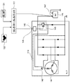
- FIG. 1 is a system configuration diagram of a vehicle in the present embodiment
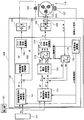
- FIG. 2 is a functional block diagram of a rotating electrical machine control device for a vehicle in the first embodiment.
- the vehicle 101 has front wheels WFR and WFL driven by an engine 111 via a transmission 113 and a differential gear 117F, and rear wheels WRR and WRL driven by a differential gear device 117R. It is.
- the present embodiment will be described using a front-wheel drive vehicle, the same effect can be obtained even if the present invention is applied to a rear-wheel drive vehicle or a four-wheel drive vehicle, and the scope of application of the present invention is not limited. .
- the generator 111 which is a rotating electrical machine, is connected to the engine 111, and the rotational driving force of the engine 111 is transmitted to generate electricity and charge the battery 144.
- the generator 114 is a field winding type rotating electrical machine, and includes a stator coil 141 and a field winding 142 as shown in FIG. As shown in FIG. 1, the generator 114 and the engine 111 are coupled together by a power transmission means 110 such as a belt so as to be integrally rotatable.
- the generator 114 can control the generated voltage by increasing or decreasing the field current.
- the control unit 131 controls the generator 114.
- the vehicle 101 is equipped with a stereo camera 121 which is an external recognition device.
- the stereo camera 121 captures the front of the vehicle 101 with the left and right cameras, and performs processing for recognizing the outside world from the captured image.
- processing for recognizing the outside world for example, information on the relative position of another vehicle stopped in front of the vehicle 101, information on display of a traffic light in front of the vehicle 101, and the like can be recognized.
- a stereo camera is used as an external recognition device.
- any other device capable of recognizing information on the relative position of other vehicles, information on signal display, etc. such as a combination of a camera and a millimeter wave radar, may be used. May be used.
- a brake pedal sensor 122 is attached to the vehicle 101.
- the brake pedal sensor 122 detects how much the brake pedal has been depressed by the driver and can calculate the required braking force of the driver. When the brake pedal is not depressed, the brake pedal non-operating state is detected.
- the vehicle 101 is provided with various vehicle sensors (not shown) for detecting the operation state of the vehicle, such as a vehicle speed sensor. Detection signals from various sensors including the brake pedal sensor 122 and external environment recognition information recognized by the stereo camera 121 are input to the control unit 131.
- the control unit 131 performs a process of controlling the field current of the generator 114 based on the external environment recognition information recognized by the stereo camera 121 and the vehicle operation information detected by various vehicle sensors.
- the control unit 131 is connected to the field control terminal 146 of the generator 114 as shown in FIG.
- a driver 145 provided in the generator 114 is connected to the field control terminal 146 and drives the switch element 143.
- the field current supplied to the field winding 142 is increased or decreased by the operation of the switch element 143, and the generated voltage by the stator coil 141 is increased or decreased.
- the generator 114 is connected to the battery 144, and the battery 144 is charged from the generator 114.
- the battery terminal 147 is connected to the control unit 131, and the battery voltage is detected by the control unit 131.
- the control unit 131 detects the voltage of the battery terminal 147 and transmits a field current command (power generation command) to the field control terminal 146 using LIN communication or the like.
- the driver 145 receives the field current command and drives the switch element 143 so that the field current of the command value flows.
- the generator 114 is provided with a driver for driving the switch element 143.
- the control unit 131 may directly control the switch element 143.
- FIG. 3 is a time chart for explaining charge / discharge control of the generator in the first embodiment.
- the control unit 131 outputs a field current command so as to be a normal generated voltage (approximately 13V to 14V) and is supplied to the field winding 142.
- the current is controlled to the initial current.
- the field current is reduced to a preset target current during acceleration. Due to the reduction of the field current, the generated voltage is reduced from the usual approximately 13V to 14V to approximately 12V.
- the field current is increased to a preset target current during deceleration to increase the power generation load. Due to the increase of the field current, the generated voltage rises from about 13V to 14V, which is normal, to about 15.5V.
- the initial current value is changed to a preset field target current value.
- the field target current value is varied depending on the state of the vehicle 101 and the state of the battery 144. There is no problem.
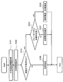
- FIG. 4 is a flowchart for explaining a control method for a rotating electrical machine in the present embodiment
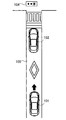
- FIG. 5 is a diagram for explaining an example of a scene for controlling the rotating electrical machine in the present embodiment.
- the control unit 131 acquires external world recognition information and vehicle operation information in steps S101 and S102 (external world recognition information acquisition means, vehicle information acquisition means).
- External world recognition information is acquired from the stereo camera 121 which is an external world recognition information means.
- the stereo camera 121 recognizes that the signal in front of the traveling path 105 of the vehicle 101 displays red (stop), and that the other vehicle 102 is stopped in front of the stereo camera 121.
- the vehicle operation information output to the control unit 131 includes information on detection signals from the vehicle speed sensor and the brake pedal sensor 122.
- the control unit 131 determines whether deceleration of the vehicle 101 is predicted based on the external environment recognition information and the vehicle information of the vehicle 101 (deceleration prediction determination means). For example, in the situation shown in FIG. 5, that is, in the situation where the signal ahead of the traveling path 105 where the vehicle 101 is traveling at a predetermined speed displays red (stop) and the other vehicle 102 stops ahead, It is determined that a deceleration of 101 is predicted.
- step S104 determines whether or not the brake pedal is in an unoperated state where no braking force is generated (brake pedal operation). Judgment means).
- step S105 processing for increasing the field current from the initial current to a preset target current during deceleration is performed. Due to the increase in the field current, the load on the generator 114 increases to provide a braking force, and the amount of power generated by the generator 114 increases.
- step S104 when the brake pedal is not in an unoperated state (no in step S104), that is, when the brake pedal is already depressed by the driver, as described with reference to FIG. Since the process of increasing the field current from the initial current to the target current at the time of deceleration is performed by the control unit 131, the process proceeds to step S107, and the process of maintaining the target current is performed.
- step S103 If it is determined that deceleration of the vehicle 101 is not predicted (no in step S103), the process proceeds to step S106, and processing for maintaining the field current at the initial current is performed.
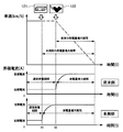
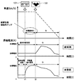
- FIG. 6 is a diagram for explaining a change in the field current by the control of the rotating electrical machine in the present embodiment.
- the brake pedal operation by the driver is used as a trigger (time t2), and the control is performed to increase the field current from the initial current to the target current at the time of deceleration.
- control is performed to increase the field current when it is determined that deceleration of the vehicle 101 is predicted based on the external world recognition information of the stereo camera 121 before the driver operates the brake pedal (time t1). I do.
- the control of increasing the field current can be performed at an earlier timing (t1) in the present invention than in the conventional example, and the power generation amount increase period can be secured longer.
- the generator 114 is a field winding type rotating electrical machine, and has a feature that the rise of torque is slow and response is low due to the large time constant of the field winding. Since the field current is increased before the driver operates the brake pedal, the controllability can be improved to cover the low responsiveness, and more power generation can be obtained. .
- a Rundel motor 118 is used instead of the generator 114, and the generator and motor are used for powering and regenerative operation. It is a configuration. For example, if the Lundel motor 118 is powered as a motor, it functions as an acceleration assist function and an engine starter function, and if it is regenerated, it has a power generation function and a regenerative brake function. In addition, if it operates as a generator, it becomes the function similar to the generator 114.
- the acceleration assist function is to add the output of the Rundel motor 118 to the output of the engine 111 by powering the Rundel motor 118 while the vehicle 101 is accelerating.
- the engine starter function is to execute the engine by powering the Rundel motor 118 when the engine 111 is stopped. 111 is to rotate and start.
- the Rundel motor 118 is driven by the engine 111 in accordance with a power generation command from the control unit 131 to generate power, a power running function to generate torque according to the power running torque command from the control unit 131, and a regenerative torque command from the control unit 131.
- a regenerative function for generating regenerative torque can be realized.
- control unit 131 issues a power generation command, similarly to the generator 114, the field current flowing in the field winding 223 is controlled to control the generated power.
- the power conversion device 400 converts the direct current power of the high voltage battery 300 into alternating current power and inputs it to the Rundel motor 118 under the control of a motor control unit 151 described later.
- Machine output (W) Torque (Nm) x Number of revolutions (r / s) Convert to
- control unit 131 When the control unit 131 issues a regenerative torque command, under the control of the motor control unit 151 described later, the AC power generated by the mechanical output by the driven rotation of the Rundel motor 118 is converted into DC power by the power converter 400, and the high voltage battery 300 Return to charge.
- the control unit 131 controls the DCDC converter 310 to convert a part of the power of the high voltage battery 300 into the voltage of the battery 144 and charge the battery 144.
- FIG. 9 is a cross-sectional view of the Rundel motor.
- the Rundel motor 118 has a configuration in which a rotor 221 is rotatably supported on the inner peripheral side of the stator 211.
- the Rundel motor 118 includes a housing 201 including a bottomed cylindrical housing case 202 and a housing cover 203 that closes an opening of the housing case 202.
- Bearings 204 are fixed to the center portions of the housing case 202 and the housing cover 203, respectively, and support the shaft 205 in a rotatable manner.
- One end of the shaft 205 protrudes through the bottom surface of the housing case 202, and a pair of slip rings 206a and 206b are attached.
- the other end of the shaft 205 protrudes through the housing cover 203 and is attached with a belt pulley 207.
- the belt pulley 207 is connected to a crankshaft of the engine 111 so as to be integrally rotatable via power transmission means 110 (see FIG. 1 or FIG. 10).
- the stator 211 includes an iron core 212 and a stator coil 213.
- An iron core 212 is disposed in the housing 201 by fitting.
- Stator coil 213 is housed in a slot provided in iron core 212.
- the rotor 221 is supported by the shaft 205 so as to be integrally rotatable on the inner peripheral side of the iron core 212 of the stator 211.
- the rotor 221 includes a claw pole 222, a field winding 223, and a permanent magnet 224.
- the pair of claw magnetic poles 222 are arranged so that the claw magnetic pole portions are positioned between the claw portions facing each other.
- Bobbins are incorporated between the claw magnetic poles 222, and field windings 223 are wound respectively.
- a plurality of permanent magnets 224 are mounted in the circumferential direction between the circumferential poles between the pair of claw magnetic poles. Depending on the required performance of the Rundel motor 118, the permanent magnet 224 may not be provided.
- Brushes 231a and 231b are slidably attached to the two slip rings 206a and 206b, respectively, and a direct current is supplied to the field winding 223.
- the claw magnetic pole type Rundel motor 118 is shown, but the invention is not limited to the claw magnetic pole type Rundel motor, and the effect of the present invention can be realized as long as the motor has a field winding in the rotor.
- FIG. 7 is a functional block diagram of the vehicle control apparatus in the second embodiment.
- the vehicle 101 includes a power conversion device 400.
- the power conversion device 400 converts the DC power of the battery 300 into AC power and supplies it to the Rundel motor 118, or converts the AC power generated by the Rundel motor 118 as a generator into DC power and returns it to the battery 300.
- the power converter 400 includes a motor control unit 151 that controls the Rundel motor 118 and an inverter 152.
- the motor control unit 151 inputs the torque command T * calculated by the control unit 131 which is a host controller and the external world recognition information from the stereo camera 121, and sends the motor current gate control signal to the six switch elements (not shown) of the inverter 152. And a field current gate control signal is output to the switch element 153.
- the inverter 152 is connected to the stator coil 213 of the Rundel motor 118.
- the stator coil 213 is provided with coils for three phases of U phase, V phase, and W phase.
- a motor current sensor 156 is attached between the inverter 152 and the Rundel motor 118.
- a position detector 157 is attached to the Rundel motor 118.
- the switch element 153 performs switching based on the field current gate control signal and controls the field current supplied to the field winding 154.
- a field current sensor 155 is attached between the field winding 154 and the switch element 153.
- the motor control unit 151 includes a motor current command calculation unit 171, a motor current control unit (PI control) 172, a dq axis three-phase conversion unit 173, a motor current gate control signal calculation unit 174, and a three-phase dq axis conversion unit. 175, a position / velocity calculation unit 176, a field current command calculation unit 161, a field current control unit (PI control) 162, and a field current gate control signal calculation unit 163.
- the motor current command calculation unit 171 inputs the torque command T *, the motor rotation speed ⁇ , and the external environment recognition information, and outputs the motor current commands Iq * and Id * that become the torque of the torque command T * at the current operating point. Determine and output.
- Id * is a current command in the magnetic flux direction (d-axis) of the motor rotor
- Iq * is a current command value in a direction (q-axis) orthogonal to the magnetic flux direction of the motor rotor.
- the torque command T * includes a power running torque command and a regenerative torque command, but the motor control algorithm is the same.
- the motor current control unit 172 performs a current control calculation on the rotation coordinate dq axes and determines voltage commands Vdc * and Vqc * on the dq axes.
- the three-phase conversion unit 173 performs coordinate conversion from the dq axis to the UVW phase, and outputs three-phase AC voltage commands Vu *, Vv *, and Vw *.
- Motor current gate control signal calculation unit 174 converts AC voltage commands Vu *, Vv *, and Vw * into gate control signals and outputs them to inverter 152.
- the inverter 152 outputs motor currents Iu, Iv, and Iw to the stator coil 213 of the Rundel motor 118 and controls the current of the stator coil 213.
- the feedback values Idc and Iqc used for current control by the motor current controller 172 are calculated by the dq converter 175 using the motor currents Iu, Iv and Iw detected by the motor current sensor 156.
- the magnetic pole position is used for the coordinate conversion calculation for obtaining the dq coordinate current from the dv coordinate voltage command to the uvw phase voltage command or the uvw phase current.
- ⁇ d is required.
- the position detector 157 is provided in the Rundel motor 118 and is obtained as a time change amount of the rotor magnetic pole position detection value ⁇ of the Rundel motor 118 together with the position speed calculation unit 176 in the motor control unit 151.
- the field current command calculation unit 161 receives the torque command T *, the motor rotation speed ⁇ , and the external field recognition information, and determines and outputs the field current command If *.
- the field current control unit 162 is based on the field current command If * output from the field current command calculation unit 161 and the field current If flowing through the field winding 154 of the Rundel motor 118 detected by the field current sensor 155. Then, the field voltage command Vf * is output, the field voltage command Vf * is converted into a gate control signal, and then the switch element 153 is driven on and off to control the field current.
- FIG. 8 is a diagram for explaining a change in the field current by the control of the rotating electrical machine in the present embodiment.
- the operation of the brake pedal by the driver is used as a trigger (time t2), the control unit 131 sends a regenerative torque command to the motor control unit 151, and the motor control unit 151
- the field current If and the motor currents Id and Iq are controlled based on the command and the brake cooperative regeneration operation (G period) is performed.
- G period the brake cooperative regeneration operation
- the control of increasing the field current If can be performed at an earlier timing (t1 to t2) in the present invention than in the conventional example, and the power generation increase period can be secured longer.
- the Rundel motor 118 which is a field winding type electric motor, has the characteristics that the rise of the torque is slow and the response is low because the time constant of the field winding 154 is large. Since the field current is increased before the driver operates the brake pedal, the low responsiveness can be covered, and a larger amount of power generation can be obtained. Therefore, it is possible to obtain a special effect that controllability can be improved and fuel consumption can be improved.
- the above-described Rundel motor 118 performs the same function as the generator 114 when the regenerative operation is not performed.
- the motor control unit 151 performs control to simply increase the power generation amount by controlling the field current.
- the switching operation of six switch elements (not shown) of the inverter 152 is controlled to perform a rectification operation to convert AC power into DC power.
- the rectification operation can be performed by the diodes of the six switch elements. In any case, the load of power generation becomes the braking force.
- the present invention is not limited to the above-described embodiments, and various designs can be made without departing from the spirit of the present invention described in the claims. It can be changed.
- the above-described embodiment has been described in detail for easy understanding of the present invention, and is not necessarily limited to one having all the configurations described.
- a part of the configuration of an embodiment can be replaced with the configuration of another embodiment, and the configuration of another embodiment can be added to the configuration of an embodiment.
Landscapes
- Engineering & Computer Science (AREA)
- Power Engineering (AREA)
- Transportation (AREA)
- Mechanical Engineering (AREA)
- Life Sciences & Earth Sciences (AREA)
- Sustainable Development (AREA)
- Sustainable Energy (AREA)
- Electric Propulsion And Braking For Vehicles (AREA)
- Hybrid Electric Vehicles (AREA)
Abstract
発電量の増大を図ることができる車両の回転電機制御装置を得ること。 本発明は、界磁巻線型回転電機114、118を有する車両101の回転電機制御装置であって、車両101の前方画像に基づいて車両101の減速が予測されると判断し、かつ車両101のブレーキペダルが未操作状態である場合に、回転電機114、118の界磁電流を増大させる制御を行うことを特徴とする。
Description
本発明は、車両の回転電機制御装置に関する。
界磁巻線を有する発電機などの界磁巻線型電動機は、界磁巻線電流の時定数が大きく、応答が一次遅れとなる。例えば、運転者が車両を発進させるときに誘導モータに励磁電流のみを与え、その後、トルク電流を流して誘導モータにトルクを発生させる技術が提案されている(特許文献1)。
一方、車両を停車させるときに界磁電流を増大させて発電量を上昇させようとすると、発電量を上昇させることが可能な発電量上昇期間は、ドライバによるブレーキペダルの操作開始から停止するまでの期間に限られ、それ以上の時間を確保することはできなかった。
本発明は、上記の点に鑑みてなされたものであり、その目的とするところは、発電量の増大を図ることができる車両の回転電機制御装置を提供することである。
上記課題を解決する本発明の車両の回転電機制御装置は、界磁電流を制御可能な回転電機を有する車両の回転電機制御装置であって、車両の前方画像に基づいて、車両の減速が予測されると判断し、かつ車両のブレーキペダルが未操作状態である場合に、界磁電流を増大させる制御を行う構成とする。
本発明によれば、ドライバがブレーキペダルを操作するよりも前に界磁電流を増大させることができ、その分だけ回転電機の発電量を増大させることができる。なお、上記した以外の課題、構成及び効果は、以下の実施形態の説明により明らかにされる。
[第1実施の形態]
次に、図1から図6を用いて、本実施の形態における車両の回転電機制御装置の構成について説明する。
次に、図1から図6を用いて、本実施の形態における車両の回転電機制御装置の構成について説明する。
図1は、本実施の形態における車両のシステム構成図、図2は、第1実施の形態における車両の回転電機制御装置の機能ブロック図である。
車両101は、図1に示すように、前輪WFR、WFLがトランスミッション113とディファレンシャルギヤ117Fを介してエンジン111により駆動され、後輪WRR、WRLがディファレンシャルギヤ装置117Rを介して従動される前輪駆動車である。尚、本実施例では前輪駆動車を用いて説明するが、後輪駆動車や四輪駆動車に本発明を適用しても同じ効果を得られ、本発明の適用範囲を制限するものではない。
エンジン111には、回転電機である発電機114が連結されており、エンジン111の回転駆動力が伝達されて発電されバッテリ144を充電する。発電機114は、界磁巻線型回転電機であり、図2に示すように、ステータコイル141と界磁巻線142を備えている。発電機114とエンジン111は、図1に示すように、ベルト等の動力伝達手段110によって互いに一体的に回転可能に連結されている。発電機114は、界磁電流を増大又は減少させることによって発電電圧を制御することができる。コントロールユニット131は、発電機114を制御する。
車両101には、外界認識装置であるステレオカメラ121が搭載されている。ステレオカメラ121は、車両101の前方を左右の2つのカメラで撮像し、撮像画像から外界を認識する処理を行う。外界を認識する処理として、例えば車両101の前方に停車している他車両の相対位置の情報、車両101の前方にある信号機の表示の情報などを認識することができる。なお、本実施例では、外界認識装置としてステレオカメラを用いているが、カメラとミリ波レーダの組み合わせなど、他車両の相対位置の情報や信号機の表示の情報などを認識できるものであれば他のものを用いても良い。
また、車両101には、ブレーキペダルセンサ122が取り付けられている。ブレーキペダルセンサ122は、ドライバによってブレーキペダルがどのくらい踏み込まれているか検出しドライバの要求制動力が計算できるようになっている。ブレーキペダルが踏み込まれていない場合はブレーキペダル未操作状態を検出する。そして、車両101には、図示していないが車速センサなど、車両の動作状態を検出するための各種車両センサが取り付けられている。ブレーキペダルセンサ122を含む各種センサの検出信号と、ステレオカメラ121により認識した外界認識情報は、コントロールユニット131に入力される。
コントロールユニット131は、ステレオカメラ121によって認識した外界認識情報と、各種車両センサによって検出した車両動作情報に基づいて、発電機114の界磁電流を制御する処理を行う。
コントロールユニット131は、図2に示すように、発電機114の界磁制御端子146に接続されている。発電機114に設けられたドライバ145は界磁制御端子146に接続されておりスイッチ素子143を駆動する。発電機114は、スイッチ素子143の操作により、界磁巻線142に通電される界磁電流が増減され、ステータコイル141による発電電圧が増減される。
発電機114は、バッテリ144に接続されており、発電機114からバッテリ144に充電がされる。また、バッテリ端子147は、コントロールユニット131に接続されており、コントロールユニット131によってバッテリ電圧の検出が行われている。
一般に、コントロールユニット131はバッテリ端子147の電圧を検出して界磁電流指令(発電指令)を界磁制御端子146にLIN通信などを使って送信する。ドライバ145は界磁電流指令を受信し、指令値の界磁電流が流れるようにスイッチ素子143を駆動する。尚、本実施例では発電機114にスイッチ素子143を駆動するドライバを設けたが、コントロールユニット131が直接スイッチ素子143を制御してもよい。
図3は、第1実施の形態における発電機の充放電制御を説明するタイムチャートである。
コントロールユニット131は、例えば、車速が定速の場合は、通常の発電電圧(略13V~14V程度)となるように、界磁電流指令を出力して界磁巻線142に通電される界磁電流を初期電流に制御する。
コントロールユニット131は、例えば、車速が定速の場合は、通常の発電電圧(略13V~14V程度)となるように、界磁電流指令を出力して界磁巻線142に通電される界磁電流を初期電流に制御する。
そして、加速時にはエンジンの負荷トルクを軽減するために、界磁電流を予め設定された加速時の目標電流まで低減させる。界磁電流の低減により、発電電圧は、通常の略13V~14V程度から略12V程度まで低下する。
一方、減速時にはエンジンの負荷トルクが増大し制動力となっても良いので、界磁電流を予め設定された減速時の目標電流まで増大ささせ発電負荷を増やす。界磁電流の増大により、発電電圧は、通常の略13V~14V程度から略15.5V程度まで上昇する。
本実施例では加速時及び減速時において、初期電流値から予め設定された界磁目標電流値まで変化させたが、車両101の状態やバッテリ144の状態によって、前記界磁目標電流値は可変させてもなんら差し支えない。
図4は、本実施の形態における回転電機の制御方法を説明するフローチャート、図5は、本実施の形態における回転電機を制御するシーンの一例を説明する図である。
コントロールユニット131は、ステップS101とステップS102により外界認識情報と車両動作情報を取得する(外界認識情報取得手段、車両情報取得手段)。外界認識情報は、外界認識情報手段であるステレオカメラ121から取得する。ステレオカメラ121は、例えば図5に示すように、車両101の走行路105の前方の信号が赤(停止)を表示し、かつ前方に他車両102が停車していることを認識し、かかる情報を外界認識情報としてコントロールユニット131に出力する。そして、コントロールユニット131に出力される車両動作情報には、車速センサとブレーキペダルセンサ122の検出信号の情報が含まれる。
コントロールユニット131は、外界認識情報と車両101の車両情報に基づいて、車両101の減速が予測されるか否かを判断する(減速予測判断手段)。例えば図5に示す状況、すなわち、車両101が所定速度で走行している走行路105の前方の信号が赤(停止)を表示し、かつ前方に他車両102が停車している状況では、車両101の減速が予測されると判断する。
車両101の減速が予測されると判断した場合には(ステップS103でyes)、ステップS104に移行し、ブレーキペダルが制動力の発生しない未操作状態であるか否かを判断する(ブレーキペダル操作判断手段)。ここで、ブレーキペダルが未操作状態である場合には(ステップS104でyes)、ステップS105に移行し、界磁電流を初期電流から予め設定された減速時の目標電流まで増大させる処理を行う。界磁電流の増大により、発電機114の負荷が増大して制動力となり、かつ、発電機114の発電量が増加される。
一方、ブレーキペダルが未操作状態ではない場合(ステップS104でno)、すなわち、既にドライバによってブレーキペダルが踏み込まれている状態である場合には、図3で説明したように、既に減速中であり、コントロールユニット131によって界磁電流を初期電流から減速時の目標電流まで増大させる処理が行われているので、ステップS107に移行し、その目標電流を維持する処理が行われる。
また、車両101の減速が予測されないと判断した場合には(ステップS103でno)、ステップS106に移行し、界磁電流を初期電流に維持する処理が行われる。
図6は、本実施の形態における回転電機の制御による界磁電流の変化を説明する図である。図6に示すように、従来例は、ドライバによるブレーキペダルの操作をトリガとして(時間t2)、界磁電流を初期電流から減速時の目標電流まで増大させる制御を行っていたのに対して、本発明では、ドライバがブレーキペダルを操作するよりも前に、ステレオカメラ121の外界認識情報に基づき車両101の減速が予測されると判断した場合(時間t1)に、界磁電流を増大させる制御を行う。
したがって、従来例よりも本発明の方がより早いタイミング(t1)で界磁電流を増大させる制御を行うことができ、発電量増大期間をより長く確保することができる。特に、発電機114は界磁巻線型回転電機であり、界磁巻線の時定数が大きいためにトルクの立ち上がりが遅く、応答性が低いという特徴を有しているが、本発明によれば、ドライバがブレーキペダルを操作するよりも前に界磁電流を増大させているので、制御性を向上させて応答性の低さをカバーすることができ、より多くの発電量を得ることができる。
[第2実施の形態]
次に、図7から図10を用いて、本発明の第2実施の形態について説明する。なお、第1実施の形態と同様の構成要素には同一の符号を付することでその詳細な説明を省略する。
次に、図7から図10を用いて、本発明の第2実施の形態について説明する。なお、第1実施の形態と同様の構成要素には同一の符号を付することでその詳細な説明を省略する。
本実施の形態において特徴的なことは、図10に記載の通り、磁巻線型回転電機として、発電機114の代わりに、ルンデルモータ118を用いて、発電機、モータの力行と回生動作として使用する構成としたことである。例えばルンデルモータ118をモータとして力行させれば、加速アシスト機能、エンジンスタータ機能、として働き、回生させれば発電機能かつ回生ブレーキ機能を持つことになる。尚、発電機として動作させれば発電機114と同様の機能となる。
加速アシスト機能とは車両101加速中にルンデルモータ118を力行させることでエンジン111の出力にルンデルモータ118の出力を上乗せすることであり、エンジンスタータ機能とはエンジン111停止時にルンデルモータ118を力行することでエンジン111を回転させ始動させることである。
ルンデルモータ118は、コントロールユニット131からの発電指令に従ってエンジン111によって回転駆動されて発電する発電機能と、コントロールユニット131からの力行トルク指令に従ってトルクを発生させる力行機能、コントロールユニット131からの回生トルク指令に従って回生トルクを発生させる回生機能、を実現可能な構成を有する。
コントロールユニット131が発電指令を出した場合は、発電機114と同様に、界磁巻線223に流れる界磁電流を制御し発電電力を制御する。
コントロールユニット131が力行指令を出した場合は、後述するモータ制御部151の制御により、電力変換装置400は高電圧バッテリ300の直流電力を交流電力に変換して、ルンデルモータ118に入力し、
機械出力(W)=トルク(Nm)×回転数(r/s)
に変換する。
機械出力(W)=トルク(Nm)×回転数(r/s)
に変換する。
コントロールユニット131が回生トルク指令を出した場合は、後述するモータ制御部151の制御により、ルンデルモータ118の被回転駆動による機械出力による交流電力は電力変換装置400によって直流電力に変換され高電圧バッテリ300に戻され充電する。尚、コントロールユニット131はDCDCコンバータ310を制御して、高電圧バッテリ300の電力の一部をバッテリ144の電圧に変換して、バッテリ144を充電する。
図9は、ルンデルモータの断面図である。
ルンデルモータ118は、ステータ211の内周側にロータ221が回転可能に支持された構成を有する。ルンデルモータ118は、有底筒状のハウジングケース202と、ハウジングケース202の開口部を閉塞するハウジングカバー203からなるハウジング201を有している。ハウジングケース202とハウジングカバー203の中心部には、それぞれベアリング204が固定されており、シャフト205を回転可能に支持している。
ルンデルモータ118は、ステータ211の内周側にロータ221が回転可能に支持された構成を有する。ルンデルモータ118は、有底筒状のハウジングケース202と、ハウジングケース202の開口部を閉塞するハウジングカバー203からなるハウジング201を有している。ハウジングケース202とハウジングカバー203の中心部には、それぞれベアリング204が固定されており、シャフト205を回転可能に支持している。
シャフト205の一方端部は、ハウジングケース202の底面を貫通して突出しており、一対のスリップリング206a、206bが取り付けられている。シャフト205の他方端部は、ハウジングカバー203を貫通して突出しており、ベルトプーリ207が取り付けられている。ベルトプーリ207は、動力伝達手段110(図1または図10を参照)を介してエンジン111のクランクシャフトに一体的に回転可能に連結されている。
ハウジング201の内部には、ステータ211とロータ221が設けられている。ステータ211は、鉄心212とステータコイル213からなる。ハウジング201には、鉄心212が嵌合いにより配置されている。ステータコイル213は、鉄心212に設けられたスロットに収納されている。
ステータ211の鉄心212の内周側には、ロータ221がシャフト205によって一体に回転可能に支持されている。ロータ221は、爪磁極222、界磁巻線223及び永久磁石224を有して構成されている。一対の爪磁極222は、それぞれの爪磁極部が対向する爪部の間に位置するように配置されている。爪磁極222の間には、ボビンが組み込まれており、それぞれ界磁巻線223が巻装されている。また、一対の爪磁極間の周方向極間には、永久磁石224が周方向に複数実装されている。尚、ルンデルモータ118の要求性能によっては永久磁石224が無い場合もある。2つのスリップリング206a、206bには、それぞれにブラシ231a、231bが摺動可能に取り付けられており、界磁巻線223に直流電流が供給されるようになっている。
本実施例においては爪磁極型のルンデルモータ118を示したが、爪磁極型のルンデルモータに限定するものではなく、ロータに界磁巻線を持つモータであれば本発明の効果を実現できる。
図7は、第2実施の形態における車両の制御装置の機能ブロック図である。
車両101は、電力変換装置400を備えている。前記電力変換装置400は、バッテリ300の直流電力を交流電力に変換しルンデルモータ118に供給したり、ジェネレータとしてルンデルモータ118で発電された交流電力を直流電力に変換しバッテリ300に戻したりしている。また電力変換装置400はルンデルモータ118を制御するモータ制御部151とインバータ152を有している。モータ制御部151は、上位コントローラであるコントロールユニット131で演算されたトルク指令T*とステレオカメラ121から外界認識情報を入力して、モータ電流ゲート制御信号をインバータ152の6つのスイッチ素子(図示せず)に対して出力し、また界磁電流ゲート制御信号をスイッチ素子153に対して出力する。
車両101は、電力変換装置400を備えている。前記電力変換装置400は、バッテリ300の直流電力を交流電力に変換しルンデルモータ118に供給したり、ジェネレータとしてルンデルモータ118で発電された交流電力を直流電力に変換しバッテリ300に戻したりしている。また電力変換装置400はルンデルモータ118を制御するモータ制御部151とインバータ152を有している。モータ制御部151は、上位コントローラであるコントロールユニット131で演算されたトルク指令T*とステレオカメラ121から外界認識情報を入力して、モータ電流ゲート制御信号をインバータ152の6つのスイッチ素子(図示せず)に対して出力し、また界磁電流ゲート制御信号をスイッチ素子153に対して出力する。
インバータ152は、ルンデルモータ118のステータコイル213に接続されている。本実施例ではステータコイル213としてU相、V相、W相の3相分のコイルが備えられている。インバータ152とルンデルモータ118との間には、モータ電流センサ156が取り付けられている。そして、ルンデルモータ118には、位置検出器157が取り付けられている。スイッチ素子153は、界磁電流ゲート制御信号に基づいてスイッチングを行い、界磁巻線154に通電される界磁電流を制御する。界磁巻線154とスイッチ素子153との間には、界磁電流センサ155が取り付けられている。
モータ制御部151は、モータ電流指令演算部171と、モータ電流制御部(PI制御)172と、dq軸三相変換部173と、モータ電流ゲート制御信号演算部174と、三相dq軸変換部175と、位置速度演算部176と、界磁電流指令演算部161と、界磁電流制御部(PI制御)162と、界磁電流ゲート制御信号演算部163とを有している。
モータ電流指令演算部171は、トルク指令T*とモータ回転速度ωと外界認識情報を入力し、現在の動作点でのトルク指令T*のトルクとなるようなモータ電流指令Iq*、Id*を決定し、出力する。ここで、Id*は、モータ回転子の磁束方向(d軸)の電流指令であり、Iq*はモータ回転子の磁束方向に直交する方向(q軸)の電流指令値である。また、トルク指令T*は力行トルク指令と回生トルク指令があるがモータ制御のアルゴリズムは同一である。
モータ電流制御部172は、回転座標d-q軸上での電流制御演算を行い、d-q軸での電圧指令Vdc*、Vqc*を決定する。三相変換部173は、d-q軸からU-V-W相への座標変換を行い、三相の交流電圧指令Vu*、Vv*、Vw*を出力する。モータ電流ゲート制御信号演算部174は、交流電圧指令Vu*、Vv*、Vw*をゲート制御信号に変換し、インバータ152に出力する。インバータ152は、ルンデルモータ118のステータコイル213にモータ電流Iu、Iv、Iwを出力して、ステータコイル213の電流を制御する。
モータ電流制御部172で電流制御に使用されるフィードバック値Idc、Iqcは、モータ電流センサ156で検出したモータ電流Iu、Iv、Iwを用いてd-q変換部175で演算される。
この制御系では、上述のように、d-q座標電圧指令からU-V-W相電圧指令、またはU-V-W相電流からd-q座標電流を得るための座標変換演算に磁極位置θdが必要となる。このため、ルンデルモータ118に位置検出器157を設けて、モータ制御部151内の位置速度演算部176と共にルンデルモータ118の回転子磁極位置検出値θの時間変化量として求められる。
界磁電流指令演算部161は、トルク指令T*とモータ回転速度ωと外界認識情報を入力し、界磁電流指令If*を決定して出力する。界磁電流制御部162は、界磁電流指令演算部161が出力した界磁電流指令If*と、界磁電流センサ155によって検出したルンデルモータ118の界磁巻線154を流れる界磁電流Ifに基づいて、界磁電圧指令Vf*を出力し、この界磁電圧指令Vf*をゲート制御信号に変換した上で、スイッチ素子153をオンオフ駆動することで、界磁電流を制御する。
図8は、本実施の形態における回転電機の制御による界磁電流の変化を説明する図である。図8に示すように、従来例は、ドライバによるブレーキペダルの操作をトリガとして(時間t2)、コントロールユニット131がモータ制御部151に回生トルク指令を送り、モータ制御部151が、コントロールユニット131の指令に基づき、界磁電流If、モータ電流Id、Iqを制御し、ブレーキ協調回生動作(G期間)を行っていたのに対して、本発明では、ドライバがブレーキペダルを操作するよりも前に、ステレオカメラ121の外界認識情報に基づき車両101の減速が予測されると判断した場合(t1)に、界磁電流Ifを増大させ発電量増加させる制御を行う。そして、ドライバがブレーキペダルを操作することによって引き続き回生動作が行われる。
したがって、従来例よりも本発明の方がより早いタイミング(t1~t2)で界磁電流Ifを増大させる制御を行うことができ、発電量増大期間をより長く確保することができる。特に、界磁巻線型電動機であるルンデルモータ118は、界磁巻線154の時定数が大きいためにトルクの立ち上がりが遅く、応答性が低いという特徴を有しているが、本発明によれば、ドライバがブレーキペダルを操作するよりも前に界磁電流を増大させているので、応答性の低さをカバーすることができ、より多くの発電量を得ることができる。したがって、制御性を向上させることができ、燃費も改善することができるという特別な効果を得ることができる。
上記したルンデルモータ118は、回生動作を行わない場合、発電機114と全く同じ働きをする。モータ制御部151は、界磁電流を制御して単純に発電量を増やす制御を行う。同時にインバータ152の6つのスイッチ素子(図示しない)のスイッチング動作を制御して整流動作行い交流電力を直流電力に変換する。または6つのスイッチ素子(図示しない)のスイッチング動作を行わない場合でも、6つのスイッチ素子のダイオードにより整流動作をすることも可能である。どの場合においても、発電の負荷分は制動力となる。
以上、本発明の実施形態について詳述したが、本発明は、前記の実施形態に限定されるものではなく、特許請求の範囲に記載された本発明の精神を逸脱しない範囲で、種々の設計変更を行うことができるものである。例えば、前記した実施の形態は本発明を分かりやすく説明するために詳細に説明したものであり、必ずしも説明した全ての構成を備えるものに限定されるものではない。また、ある実施形態の構成の一部を他の実施形態の構成に置き換えることが可能であり、また、ある実施形態の構成に他の実施形態の構成を加えることも可能である。さらに、各実施形態の構成の一部について、他の構成の追加・削除・置換をすることが可能である。
101 車両
114 発電機(回転電機)
118 ルンデルモータ(回転電機)
121 ステレオカメラ
122 ブレーキペダルセンサ
131 コントロールユニット
141 ステータコイル
142 界磁巻線
143 スイッチ素子
144 バッテリ
145 ドライバ
146 界磁制御端子
147 バッテリ端子
151 モータ制御部
152 インバータ
153 スイッチ素子
154 界磁巻線
213 ステータコイル
300 高電圧バッテリ
310 DCDCコンバータ
400 電力変換装置
114 発電機(回転電機)
118 ルンデルモータ(回転電機)
121 ステレオカメラ
122 ブレーキペダルセンサ
131 コントロールユニット
141 ステータコイル
142 界磁巻線
143 スイッチ素子
144 バッテリ
145 ドライバ
146 界磁制御端子
147 バッテリ端子
151 モータ制御部
152 インバータ
153 スイッチ素子
154 界磁巻線
213 ステータコイル
300 高電圧バッテリ
310 DCDCコンバータ
400 電力変換装置
Claims (4)
- 界磁巻線型回転電機を有する車両の回転電機制御装置であって、
前記車両の前方画像に基づいて前記車両の減速が予測されると判断し、かつ前記車両のブレーキペダルが制動力の発生しない未操作状態である場合に、前記界磁巻線型回転電機の界磁電流を増大させる制御を行うことを特徴とする車両の回転電機制御装置。 - ステレオカメラにより撮像した前記車両の前方画像に基づいて外界認識情報を取得する外界認識情報取得手段と、
車両センサにより検知した前記車両の動作情報を取得する車両情報取得手段と、
前記外界認識情報と前記車両情報に基づいて前記車両の減速が予測されるかを判断する減速予測判断手段と、
該減速予測判断手段により前記車両の減速が予測されると判断した場合に、前記車両情報に基づいてブレーキペダルが制動力の発生しない未操作状態であるかを判断するブレーキペダル操作判断手段と、を有し、
該ブレーキペダル操作判断手段により前記ブレーキペダルが制動力の発生しない未操作状態であると判断された場合に、前記界磁電流を初期電流から予め設定された減速時の目標電流まで増大させる制御を行うことを特徴とする請求項1に記載の車両の回転電機制御装置。 - 前記ブレーキペダル操作判断手段により前記ブレーキペダルが制動力の発生しない未操作状態から操作されたと判断した場合に、前記界磁電流を前記減速時の目標電流に維持する制御を行うことを特徴とする請求項2に記載の車両の回転電機制御装置。
- 前記ブレーキペダル操作判断手段により前記ブレーキペダルが制動力の発生しない未操作状態から操作されたと判断した場合に、上位コントローラからのトルク指令に基づいて前記界磁電流と、前記界磁巻線型回転電機のステータコイルに供給されるモータ電流とを制御して回生動作を行わせるモータ制御部を有することを特徴とする請求項2に記載の車両の回転電機制御装置。
Priority Applications (1)
| Application Number | Priority Date | Filing Date | Title |
|---|---|---|---|
| JP2015519704A JPWO2014192371A1 (ja) | 2013-05-31 | 2014-03-14 | 車両の回転電機制御装置 |
Applications Claiming Priority (2)
| Application Number | Priority Date | Filing Date | Title |
|---|---|---|---|
| JP2013115883 | 2013-05-31 | ||
| JP2013-115883 | 2013-05-31 |
Publications (1)
| Publication Number | Publication Date |
|---|---|
| WO2014192371A1 true WO2014192371A1 (ja) | 2014-12-04 |
Family
ID=51988415
Family Applications (1)
| Application Number | Title | Priority Date | Filing Date |
|---|---|---|---|
| PCT/JP2014/056822 Ceased WO2014192371A1 (ja) | 2013-05-31 | 2014-03-14 | 車両の回転電機制御装置 |
Country Status (2)
| Country | Link |
|---|---|
| JP (1) | JPWO2014192371A1 (ja) |
| WO (1) | WO2014192371A1 (ja) |
Citations (3)
| Publication number | Priority date | Publication date | Assignee | Title |
|---|---|---|---|---|
| JPH05292602A (ja) * | 1992-04-09 | 1993-11-05 | Toyota Motor Corp | 電気自動車用制動装置 |
| JPH0614415A (ja) * | 1992-06-24 | 1994-01-21 | Hitachi Ltd | 電動車用制御装置 |
| JP2007282406A (ja) * | 2006-04-07 | 2007-10-25 | Tokyo Metropolitan Univ | 自動車の制動力制御システム |
Family Cites Families (5)
| Publication number | Priority date | Publication date | Assignee | Title |
|---|---|---|---|---|
| JP5088251B2 (ja) * | 2008-06-30 | 2012-12-05 | 日本電気株式会社 | 通信システム |
| JP5057166B2 (ja) * | 2008-10-30 | 2012-10-24 | アイシン・エィ・ダブリュ株式会社 | 安全運転評価システム及び安全運転評価プログラム |
| JP5644168B2 (ja) * | 2010-04-22 | 2014-12-24 | トヨタ自動車株式会社 | 運転支援装置 |
| JP5703597B2 (ja) * | 2010-06-02 | 2015-04-22 | トヨタ自動車株式会社 | 運転支援装置 |
| JP2013045176A (ja) * | 2011-08-22 | 2013-03-04 | Pioneer Electronic Corp | 信号機認識装置、候補点パターン送信装置、候補点パターン受信装置、信号機認識方法、及び候補点パターン受信方法 |
-
2014
- 2014-03-14 JP JP2015519704A patent/JPWO2014192371A1/ja active Pending
- 2014-03-14 WO PCT/JP2014/056822 patent/WO2014192371A1/ja not_active Ceased
Patent Citations (3)
| Publication number | Priority date | Publication date | Assignee | Title |
|---|---|---|---|---|
| JPH05292602A (ja) * | 1992-04-09 | 1993-11-05 | Toyota Motor Corp | 電気自動車用制動装置 |
| JPH0614415A (ja) * | 1992-06-24 | 1994-01-21 | Hitachi Ltd | 電動車用制御装置 |
| JP2007282406A (ja) * | 2006-04-07 | 2007-10-25 | Tokyo Metropolitan Univ | 自動車の制動力制御システム |
Also Published As
| Publication number | Publication date |
|---|---|
| JPWO2014192371A1 (ja) | 2017-02-23 |
Similar Documents
| Publication | Publication Date | Title |
|---|---|---|
| JP4466882B2 (ja) | 電動機の制御装置 | |
| JP7457701B2 (ja) | トラクションコントロールシステム | |
| EP0954092B1 (en) | Drive control apparatus for electric synchronous machine having field winding | |
| CN101657962B (zh) | 电动机的控制装置 | |
| JP4906825B2 (ja) | 車両挙動制御装置 | |
| US7728557B2 (en) | Electric discharge controller, electric discharge control method and its program | |
| US7741792B2 (en) | Motor control device | |
| Huang et al. | An accurate torque control of permanent magnet brushless motor using low-resolution hall-effect sensors for light electric vehicle applications | |
| JP5329801B2 (ja) | 可変磁束ドライブシステム | |
| JP5076530B2 (ja) | 電力供給装置及び車両の駆動力制御装置 | |
| JP3985550B2 (ja) | 電動車両駆動制御装置、電動車両駆動制御方法及びそのプログラム | |
| JP2016073061A (ja) | 電気自動車の制御装置 | |
| JP2021127015A (ja) | 移動体の制御装置 | |
| JP6497231B2 (ja) | モータ制御装置 | |
| JPWO2014192371A1 (ja) | 車両の回転電機制御装置 | |
| JPH10117403A (ja) | 電気車用ハイブリッド駆動システム | |
| JP2008079420A (ja) | 電気自動車 | |
| JP6137045B2 (ja) | 車両の駆動電動機制御装置 | |
| US10819267B2 (en) | Controller for switched reluctance motor | |
| JP2004159400A (ja) | ハイブリッド車両における磁束検出装置 | |
| JP5293218B2 (ja) | 車両用モータ制御装置及びその方法 | |
| JP2007267514A (ja) | 電動4輪駆動車及び電動4輪駆動車に用いられる電動モータ | |
| JP2008062688A (ja) | モータの制御装置 | |
| JP2007259575A (ja) | 界磁巻線型同期電動機及び電動駆動装置 | |
| JP2016067147A (ja) | 電気自動車制御装置 |
Legal Events
| Date | Code | Title | Description |
|---|---|---|---|
| 121 | Ep: the epo has been informed by wipo that ep was designated in this application |
Ref document number: 14804022 Country of ref document: EP Kind code of ref document: A1 |
|
| ENP | Entry into the national phase |
Ref document number: 2015519704 Country of ref document: JP Kind code of ref document: A |
|
| NENP | Non-entry into the national phase |
Ref country code: DE |
|
| 122 | Ep: pct application non-entry in european phase |
Ref document number: 14804022 Country of ref document: EP Kind code of ref document: A1 |