WO2014192174A1 - Motor grader - Google Patents
Motor grader Download PDFInfo
- Publication number
- WO2014192174A1 WO2014192174A1 PCT/JP2013/075939 JP2013075939W WO2014192174A1 WO 2014192174 A1 WO2014192174 A1 WO 2014192174A1 JP 2013075939 W JP2013075939 W JP 2013075939W WO 2014192174 A1 WO2014192174 A1 WO 2014192174A1
- Authority
- WO
- WIPO (PCT)
- Prior art keywords
- frame
- reducing agent
- fuel tank
- tank
- side frame
- Prior art date
Links
Images


Classifications
-
- E—FIXED CONSTRUCTIONS
- E02—HYDRAULIC ENGINEERING; FOUNDATIONS; SOIL SHIFTING
- E02F—DREDGING; SOIL-SHIFTING
- E02F9/00—Component parts of dredgers or soil-shifting machines, not restricted to one of the kinds covered by groups E02F3/00 - E02F7/00
- E02F9/08—Superstructures; Supports for superstructures
- E02F9/0858—Arrangement of component parts installed on superstructures not otherwise provided for, e.g. electric components, fenders, air-conditioning units
- E02F9/0883—Tanks, e.g. oil tank, urea tank, fuel tank
-
- B—PERFORMING OPERATIONS; TRANSPORTING
- B60—VEHICLES IN GENERAL
- B60K—ARRANGEMENT OR MOUNTING OF PROPULSION UNITS OR OF TRANSMISSIONS IN VEHICLES; ARRANGEMENT OR MOUNTING OF PLURAL DIVERSE PRIME-MOVERS IN VEHICLES; AUXILIARY DRIVES FOR VEHICLES; INSTRUMENTATION OR DASHBOARDS FOR VEHICLES; ARRANGEMENTS IN CONNECTION WITH COOLING, AIR INTAKE, GAS EXHAUST OR FUEL SUPPLY OF PROPULSION UNITS IN VEHICLES
- B60K13/00—Arrangement in connection with combustion air intake or gas exhaust of propulsion units
- B60K13/04—Arrangement in connection with combustion air intake or gas exhaust of propulsion units concerning exhaust
-
- B—PERFORMING OPERATIONS; TRANSPORTING
- B60—VEHICLES IN GENERAL
- B60K—ARRANGEMENT OR MOUNTING OF PROPULSION UNITS OR OF TRANSMISSIONS IN VEHICLES; ARRANGEMENT OR MOUNTING OF PLURAL DIVERSE PRIME-MOVERS IN VEHICLES; AUXILIARY DRIVES FOR VEHICLES; INSTRUMENTATION OR DASHBOARDS FOR VEHICLES; ARRANGEMENTS IN CONNECTION WITH COOLING, AIR INTAKE, GAS EXHAUST OR FUEL SUPPLY OF PROPULSION UNITS IN VEHICLES
- B60K15/00—Arrangement in connection with fuel supply of combustion engines or other fuel consuming energy converters, e.g. fuel cells; Mounting or construction of fuel tanks
- B60K15/03—Fuel tanks
- B60K15/063—Arrangement of tanks
-
- E—FIXED CONSTRUCTIONS
- E02—HYDRAULIC ENGINEERING; FOUNDATIONS; SOIL SHIFTING
- E02F—DREDGING; SOIL-SHIFTING
- E02F3/00—Dredgers; Soil-shifting machines
- E02F3/04—Dredgers; Soil-shifting machines mechanically-driven
- E02F3/76—Graders, bulldozers, or the like with scraper plates or ploughshare-like elements; Levelling scarifying devices
- E02F3/7636—Graders with the scraper blade mounted under the tractor chassis
- E02F3/764—Graders with the scraper blade mounted under the tractor chassis with the scraper blade being pivotable about a vertical axis
-
- E—FIXED CONSTRUCTIONS
- E02—HYDRAULIC ENGINEERING; FOUNDATIONS; SOIL SHIFTING
- E02F—DREDGING; SOIL-SHIFTING
- E02F3/00—Dredgers; Soil-shifting machines
- E02F3/04—Dredgers; Soil-shifting machines mechanically-driven
- E02F3/76—Graders, bulldozers, or the like with scraper plates or ploughshare-like elements; Levelling scarifying devices
- E02F3/7636—Graders with the scraper blade mounted under the tractor chassis
- E02F3/7645—Graders with the scraper blade mounted under the tractor chassis with the scraper blade being pivotable about a horizontal axis disposed parallel to the blade
-
- E—FIXED CONSTRUCTIONS
- E02—HYDRAULIC ENGINEERING; FOUNDATIONS; SOIL SHIFTING
- E02F—DREDGING; SOIL-SHIFTING
- E02F3/00—Dredgers; Soil-shifting machines
- E02F3/04—Dredgers; Soil-shifting machines mechanically-driven
- E02F3/76—Graders, bulldozers, or the like with scraper plates or ploughshare-like elements; Levelling scarifying devices
- E02F3/7636—Graders with the scraper blade mounted under the tractor chassis
- E02F3/765—Graders with the scraper blade mounted under the tractor chassis with the scraper blade being pivotable about a horizontal axis disposed perpendicular to the blade
-
- E—FIXED CONSTRUCTIONS
- E02—HYDRAULIC ENGINEERING; FOUNDATIONS; SOIL SHIFTING
- E02F—DREDGING; SOIL-SHIFTING
- E02F3/00—Dredgers; Soil-shifting machines
- E02F3/04—Dredgers; Soil-shifting machines mechanically-driven
- E02F3/76—Graders, bulldozers, or the like with scraper plates or ploughshare-like elements; Levelling scarifying devices
- E02F3/7636—Graders with the scraper blade mounted under the tractor chassis
- E02F3/7654—Graders with the scraper blade mounted under the tractor chassis with the scraper blade being horizontally movable into a position near the chassis
-
- B—PERFORMING OPERATIONS; TRANSPORTING
- B60—VEHICLES IN GENERAL
- B60K—ARRANGEMENT OR MOUNTING OF PROPULSION UNITS OR OF TRANSMISSIONS IN VEHICLES; ARRANGEMENT OR MOUNTING OF PLURAL DIVERSE PRIME-MOVERS IN VEHICLES; AUXILIARY DRIVES FOR VEHICLES; INSTRUMENTATION OR DASHBOARDS FOR VEHICLES; ARRANGEMENTS IN CONNECTION WITH COOLING, AIR INTAKE, GAS EXHAUST OR FUEL SUPPLY OF PROPULSION UNITS IN VEHICLES
- B60K15/00—Arrangement in connection with fuel supply of combustion engines or other fuel consuming energy converters, e.g. fuel cells; Mounting or construction of fuel tanks
- B60K15/03—Fuel tanks
- B60K15/063—Arrangement of tanks
- B60K2015/0634—Arrangement of tanks the fuel tank is arranged below the vehicle floor
-
- B—PERFORMING OPERATIONS; TRANSPORTING
- B60—VEHICLES IN GENERAL
- B60K—ARRANGEMENT OR MOUNTING OF PROPULSION UNITS OR OF TRANSMISSIONS IN VEHICLES; ARRANGEMENT OR MOUNTING OF PLURAL DIVERSE PRIME-MOVERS IN VEHICLES; AUXILIARY DRIVES FOR VEHICLES; INSTRUMENTATION OR DASHBOARDS FOR VEHICLES; ARRANGEMENTS IN CONNECTION WITH COOLING, AIR INTAKE, GAS EXHAUST OR FUEL SUPPLY OF PROPULSION UNITS IN VEHICLES
- B60K15/00—Arrangement in connection with fuel supply of combustion engines or other fuel consuming energy converters, e.g. fuel cells; Mounting or construction of fuel tanks
- B60K15/03—Fuel tanks
- B60K15/063—Arrangement of tanks
- B60K2015/0638—Arrangement of tanks the fuel tank is arranged in the rear of the vehicle
-
- B—PERFORMING OPERATIONS; TRANSPORTING
- B60—VEHICLES IN GENERAL
- B60Y—INDEXING SCHEME RELATING TO ASPECTS CROSS-CUTTING VEHICLE TECHNOLOGY
- B60Y2200/00—Type of vehicle
- B60Y2200/40—Special vehicles
- B60Y2200/41—Construction vehicles, e.g. graders, excavators
- B60Y2200/411—Bulldozers, Graders
Definitions
- the present invention relates to a motor grader.
- a motor grader is provided with a fuel tank at the rear of the vehicle body for refueling (see, for example, Patent Document 1).
- the body frame of the motor grader shown in Patent Document 1 has side frames disposed on the left and right sides of the fuel tank in the vehicle width direction, and a rear frame provided behind the fuel tank.
- the fuel tank is supported by the vehicle body frame by mounting portions provided on the side frame and the rear frame.
- an exhaust treatment device for treating exhaust on a motor grader is connected to the engine via a connection pipe in order to process exhaust from the engine.
- a selective reduction catalyst device that reduces nitrogen oxide (NOx) in exhaust gas may be used.
- the selective catalytic reduction device treats exhaust gas using a reducing agent such as urea water. For this reason, it is necessary to arrange
- the reducing agent tank be arranged at the same height as the fuel tank in order to facilitate replenishment of the reducing agent.
- the reducing agent tank when the reducing agent tank is arranged, the reducing agent tank has to be arranged on the rear side of the rear frame supporting the fuel tank on the rear side of the fuel tank, and the length of the vehicle body becomes long. If it becomes longer, there arises a problem that the steering performance and the weight balance of the vehicle body deteriorate.
- An object of the present invention is to provide a motor grader capable of suppressing the extension of the vehicle body due to the installation of a reducing agent tank in consideration of the problems of the conventional motor grader.
- a motor grader according to a first invention includes a fuel tank, a vehicle body frame, a side support portion, a rear support portion, and a reducing agent tank.
- the fuel tank stores fuel.
- the vehicle body frame has a pair of first and second side frames disposed on both sides of the fuel tank in the vehicle width direction, and supports the fuel tank.
- the side support portions are provided on both sides of the fuel tank in the vehicle width direction and on each of the pair of first side frame and second side frame, and fix the fuel tank to the vehicle body frame.
- the rear support portion is disposed on the first side frame behind the fuel tank and fixes the fuel tank to the vehicle body frame.
- the reducing agent tank is close to the rear side of the fuel tank and is disposed closer to the second side frame from the center in the vehicle width direction, and stores a reducing agent that processes exhaust from the engine.
- the rear support portion for fixing the fuel tank to the vehicle body frame is disposed on one of the first side frames of the left and right side frames in the vehicle width direction.
- positions a reducing agent tank from the center to the other 2nd side frame can be formed in the vehicle width direction. Therefore, the reducing agent tank can be disposed close to the rear side of the fuel tank.
- the rear support portion is attached to the first side frame and is provided so as to protrude from the first side frame toward the second side frame.
- the reducing agent tank is disposed between the rear support portion and the second side frame when viewed from the front-rear direction of the vehicle body and at a position overlapping at least a part of the rear support portion when viewed from the vehicle width direction. .
- the rear support for fixing the fuel tank to the vehicle body frame is attached to the first side frame.
- the reducing agent is positioned between the rear support portion and the second side frame as viewed from the front-rear direction of the vehicle body and at the rear side of the fuel tank, and overlaps at least a part of the rear support portion as viewed from the vehicle width direction.
- a tank can be arranged.
- the reducing agent tank when installed, it can be installed while suppressing the extension of the motor grader body length.
- the vehicle body frame has a rear frame disposed on the rear side of the reducing agent tank.
- the reducing agent tank is supported by the rear frame.
- a gap is formed between the fuel tank and the reducing agent tank.
- the reducing agent in the tank can be kept in a predetermined temperature range, and nitrogen oxides can be processed efficiently.
- the reducing agent tank has a liquid supply port to which the reducing agent is supplied, and the liquid supply port is provided on the second side frame side.
- the rear support portion is disposed on the first side frame, and the liquid supply port is provided on the opposite side of the second side frame.
- the liquid supply port is provided on the side of the vehicle body rather than providing the liquid supply port on the side opposite to the rear support part, rather than providing the liquid supply port on the same side as the rear support part.
- the motor grader which can suppress the expansion
- FIG. 5 is a rear plan view of FIG. 4.
- the perspective view which shows the external appearance of the fuel tank main body of FIG. The perspective view which shows the state which removed the fuel tank from FIG.
- the bottom view of FIG. The top view which shows the 1st flame
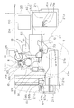
- FIG. 1 is an external perspective view of the motor grader of the present embodiment.
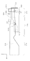
- FIG. 2 is a side view of the motor grader of the present embodiment.
- the motor grader 1 includes a front wheel 11 and a rear wheel 12.
- a pair of front wheels 11 are provided on the left and right sides of the vehicle body.
- the rear wheel 12 has a pair of left and right rear wheels 12a and a pair of left and right rear wheels 12b.
- the rear wheel 12a and the rear wheel 12b are arranged such that the rear wheel 12a is arranged on the rear side of the rear wheel 12b.
- the motor grader 1 can perform leveling work, snow removal work, light cutting, material mixing, and the like with a blade 42 provided between the front wheel 11 and the rear wheel 12.
- the front-rear direction means the front-rear direction of the vehicle body as viewed from the operator seated in the cab 3.
- the left-right direction or the side means the vehicle width direction of the motor grader 1 and is the left-right direction as viewed from the operator seated in the cab 3.
- the front-rear direction is indicated by the x axis
- the left-right direction is indicated by the y-axis
- the up-down direction is indicated by the z-axis.
- the motor grader 1 includes components (see FIG. 3) arranged in a vehicle body frame 2, an operator cab 3, a work implement 4, and an engine compartment 6.
- the vehicle body frame 2 includes a first frame 21, a second frame 22, and an exterior cover 25 as shown in FIGS. 1 and 2.
- the second frame 22 is attached to the front of the first frame 21 through a center pin (not shown) so as to be articulateable.
- the first frame 21 supports the exterior cover 25, components disposed in the engine chamber 6 described later, and the like.
- the exterior cover 25 covers the engine compartment 6.
- the first frame 21 is provided with the rear wheel 12 described above. These rear wheels 12 are rotationally driven by the driving force from the engine 61 (see FIG. 3), so that the vehicle travels.
- a front wheel 11 is provided at the front end of the second frame 22.
- the cab 3 is placed on the second frame 22. Inside the cab 3 are provided a handle, a speed change lever, an operation lever of the work machine 4, a brake, an accelerator pedal, an inching pedal, and the like (not shown). The cab 3 may be placed on the first frame 21.
- the work machine 4 includes a draw bar 40, a circle 41, a blade 42, a hydraulic motor 49, various hydraulic cylinders 44 to 48, and the like. These hydraulic cylinders 44 to 48 are cylinders driven by hydraulic pressure supplied from a hydraulic pump.
- the front end portion of the draw bar 40 is swingably attached to the front end portion of the second frame 22.
- the second frame 22 and the draw bar 40 are provided with a pair of lift cylinders 44 and 45 that are arranged substantially in the vertical direction. These lift cylinders 44 and 45 are provided so as to be separated from each other with the second frame 22 interposed therebetween.
- the rear end of the draw bar 40 moves up and down by the synchronized expansion and contraction of the pair of lift cylinders 44 and 45.
- the draw bar 40 is tilted up and down around an axis along the vehicle traveling direction by different expansion and contraction of the lift cylinders 44 and 45.
- a drawbar shift cylinder 46 is attached to the side ends of the second frame 22 and the drawbar 40.
- the drawbar shift cylinder 46 is disposed to be inclined with respect to the vertical direction.
- the position of the draw bar 40 with respect to the horizontal direction (left and right direction) can be changed by the expansion and contraction of the draw bar shift cylinder 46.
- the circle 41 is rotatably attached to the rear end portion of the draw bar 40.
- the circle 41 is driven by a hydraulic motor 49 (see FIG. 1).
- the hydraulic motor 49 can rotate the circle 41 by being driven by pressure oil supplied from a hydraulic pump (not shown).
- the circle 41 rotates clockwise or counterclockwise with respect to the draw bar 40 as viewed from above the vehicle.
- Blade 42 The blade 42 is supported so as to be slidable in the left-right direction with respect to the circle 41 and swingable up and down around an axis parallel to the left-right direction.
- a blade shift cylinder 47 supported by a circle is attached to the blade 42.
- the blade shift cylinder 47 is provided along the longitudinal direction of the blade. By expansion and contraction of the blade shift cylinder 47, the blade 42 can move in the left-right direction (the longitudinal direction of the blade 42) with respect to the circle 41.
- a tilt cylinder 48 (see FIG. 2) supported by the circle 41 is attached to the blade 42.
- the tilt cylinder 48 can expand and contract to swing the blade 42 about an axis parallel to the horizontal direction (left-right direction) and change the tilt in the vertical direction.
- the tilt cylinder 48 can change the tilt angle with respect to the traveling direction of the blade 42.
- the blade 42 can be moved in the vertical direction by moving the rear end of the draw bar 40 up and down by the lift cylinders 44 and 45 described above. Further, the lateral position of the blade 42 can be changed by changing the lateral position of the draw bar 40 by the draw bar shift cylinder 46.
- the blade 42 can move up and down with respect to the vehicle, change the inclination with respect to the traveling direction, change the inclination with respect to the lateral direction, rotate, and shift in the left-right direction via the draw bar 40 and the circle 41. .
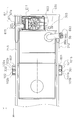
- FIG. 3 is a right side view of the internal structure of the engine compartment 6.
- the outer shapes of the first frame 21 on the right side of the vehicle, the exterior cover 25, and the rear wheel 12 a on the rear side are shown by two-dot chain lines.
- the first frame 21 has a front portion 21a, a central portion 21b, and a rear portion 21c in order from the front to the rear.
- an engine 61, a power transmission device 7, a radiator 65, a post-processing unit 8, a hydraulic oil tank 110, and the like are arranged in the engine chamber 6. Below them, a fuel tank 66 and a reducing agent tank 67 are arranged. The fuel tank 66 and the reducing agent tank 67 are attached to the first frame 21.
- the fuel stored in the fuel tank 66 is supplied to the engine 61.
- the engine 61 burns this fuel to generate a driving force, and transmits the driving force to the torque converter 62 and a hydraulic pump (not shown).
- the engine 61 is disposed in front of the center axis S of the axle of the rear wheel 12a.
- the mount bracket 70 is attached to the engine 61.
- the mount bracket 70 is elastically attached to the central portion 21 b of the first frame 21 by a damper 73.
- the mount bracket 70 and the damper 73 are also provided on the left side.
- the power transmission device 7 is disposed in the front part in the engine compartment 6 and includes a torque converter 62 and a transmission 63.
- the torque converter 62 is disposed on the output side of the engine 61 with respect to the transmission 63.
- a hydraulic oil tank 110 is disposed above the torque converter 62 and the transmission 63.
- a flange 63a is attached to the transmission 63, and the flange 63a is attached to the front portion 21a of the first frame 21 by dampers 79a and 79b. In this way, the torque converter 62 and the transmission 63 are elastically supported by the first frame 21.
- the flange 63a and the dampers 79a and 79b are provided in a pair of left and right.
- the transmission 63 has a hydraulic clutch and a transmission gear (not shown) therein.
- the transmission 63 converts the rotational speed and torque of the input shaft connected to the output side of the torque converter 62.
- the converted rotational speed and torque are finally transmitted from the output shaft of the transmission 63 to the rear wheel 12 via a final reduction gear and a tandem device (not shown).
- the vehicle travels when the rear wheel 12 is rotationally driven.
- a hydraulic pump (not shown) is provided in the transmission 63.
- the hydraulic pump drives the various clutches of the transmission 63, the hydraulic motor 49, and the various cylinders 44 to 48 by the hydraulic pressure of the hydraulic oil stored in the hydraulic oil tank 110.
- the radiator 65 cools the cooling water of the engine 61.
- the radiator 65 is provided behind the engine 61 and the post-processing unit 8.
- the radiator 65 is supported by the rear portion 21 c of the first frame 21. Due to the shape of the first frame 21, the radiator 65 is supported by the first frame 21 at a position lower than the position where the mount bracket 70 is supported.
- the post-processing unit 8 includes a first post-processing device 91, a second post-processing device 92, a connecting pipe 93 that connects the first post-processing device 91 and the second post-processing device 92, and a reducing agent injection device 94. ing. Further, a connection pipe 69 for sending the exhaust of the engine 61 to the first post-processing device 91 and an exhaust pipe 26 for discharging the exhaust processed by the post-processing unit 8 to the outside are provided.
- the first post-treatment device 91 is, for example, a diesel particulate filter device, and collects particulate matter contained in the exhaust gas with a filter.
- the collected particulate matter is incinerated by a heater attached to the filter.
- the first post-processing device 91 is disposed between the radiator 65 and the engine 61.
- the first post-processing device 91 has a substantially cylindrical outer shape, and is arranged so that its central axis is along the vehicle width direction.
- the second post-treatment device 92 is, for example, a selective reduction catalyst device, and selectively reduces nitrogen oxides NOx using a reducing agent with respect to the exhaust discharged from the first post-treatment device 91.
- the second post-processing device 92 has a substantially cylindrical outer shape, and is arranged so that its central axis is along the vehicle width direction.
- the connecting pipe 93 that connects the first post-processing apparatus 91 and the second post-processing apparatus 92 is disposed on the upper side of the first post-processing apparatus 91, and the second post-processing apparatus 92 is disposed on the front side of the connecting pipe 93. Yes.
- a reducing agent injection device 94 for injecting the reducing agent is provided in the connection pipe 93.
- the 2nd post-processing apparatus 92 is arrange
- the exhaust pipe 26 is connected to the second post-treatment device 92, and the upper part of the exhaust pipe 26 protrudes upward from the exterior cover 25.
- the engine 61, the connecting pipe 69, the first aftertreatment device 91, the connecting tube 93, the second aftertreatment device 92, and the exhaust pipe 26 are connected in series in this order. Therefore, the exhaust from the engine 61 passes through the first connecting pipe 69 and is sent to the first post-processing device 91. In the first post-treatment device 91, the particulate matter is mainly reduced from the exhaust gas. Next, the exhaust gas passes through the connection pipe 93 and is sent to the second post-processing device 92. In the second post-processing device 92, NOx is mainly reduced. Thereafter, the cleaned exhaust gas is discharged to the outside through the exhaust pipe 26.
- the post-processing unit 8 is provided with a post-processing device support mount bracket 80, and the post-processing device support mount bracket 80 is supported by the mount bracket 70 at one end of the mount bracket 70. As described above, the post-processing unit 8 is elastically supported by the central portion 21 a of the first frame 21 via the post-processing device support mounting bracket 80 and the mounting bracket 70.
- the torque converter 62 and the transmission 63, the torque converter 62 and the engine 61, the engine 61 and the mount bracket 70, and the mount bracket 70 and the post-processing unit 8 are connected to each other. It is connected to the first frame 21 via 79a, 79b, 73. Therefore, the torque converter 62, the transmission 63, the engine 61, and the post-processing unit 8 vibrate together and are not easily affected by vibration from the first frame 21.
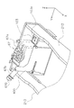
- FIG. 4 is a perspective view showing the appearance of the first frame 21, the fuel tank 66, and the reducing agent tank 67 of the present embodiment.
- the left direction in the figure is the front of the vehicle body.
- FIG. 5 is a side view of the first frame 21 of the present embodiment.
- FIG. 5 also shows the positions of the fuel tank 66 and the reducing agent tank 67.
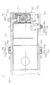
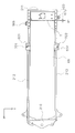
- FIG. 6 is a plan view showing the first frame 21, the fuel tank 66, and the reducing agent tank 67 of the present embodiment.
- the first frame 21 has a substantially rectangular shape when viewed from above.
- the first frame 21 includes a front frame 210, a rear frame 211, a left side frame 212, and a right side frame 213.
- Each frame is a substantially plate-like member, and is arranged so that its plane is parallel to the vertical direction.
- the front frame 210 and the rear frame 211 are arranged along the vehicle width direction (left-right direction).
- the left side frame 212 connects the left ends of the front frame 210 and the rear frame 211.
- the right side frame 213 connects the right ends of the front frame 210 and the rear frame 211.
- the left mount portion 101 that supports the fuel tank 66 is provided so as to protrude outward (leftward) from the above-described center portion of the left side frame 212 toward the lower end near the rear.
- the left mount 101 is formed in a substantially U shape when viewed from the left side of the vehicle body.
- the left mount portion 101 has a first mount portion 101a and a pair of second mount portions 101b.
- the first mount portion 101a has a substantially rectangular shape provided perpendicular to the side surface of the left side frame 212, and has a through hole (not shown) into which the bolt 301 is inserted.
- the second mount portion 101b has a substantially triangular shape and extends upward from the front end and the rear end of the first mount portion 101a.
- the second mount portion 101b is fixed vertically to the surface of the left side frame 212.
- the right mount 102 is provided outward at the position of the right frame 213 opposite to the position of the left frame 212 where the left mount 101 is disposed. ing.
- the shape of the right mount portion 102 is the same as that of the left mount portion 101, and a bolt 302 is inserted.
- the left mount portion 101 and the right mount portion 102 are arranged symmetrically with respect to the center line L of the first frame 21 in the vehicle width direction.
- a rear mount portion 103 is provided behind the left mount portion 101 and inside the left side frame 212 to support the fuel tank 66.
- the rear mounting portion 103 is provided at the rear portion of the left side frame 212 and is formed so as to protrude from the left side frame 212 toward the right side frame 213.
- the rear mount portion 103 is a plate-like member disposed from the lower end of the rear portion of the left side frame 212 toward the right side frame 213 side.
- a through hole 103s (see FIG. 8) into which the bolt 303 is inserted is formed at the tip of the rear mount portion 103.
- the rear mounting portion 103 is formed near the left side frame 212.
- the fuel tank 66 is provided below the post-processing unit 8 and the radiator 65 and is supported by the first frame 21.
- the fuel tank 66 extends from the lower side of the engine 61 toward the rear of the vehicle.
- the fuel tank 66 includes a fuel tank main body 66a, a fuel filler 66b, a left side mounting part 601, a right side mounting part 602, and a rear side mounting part 603.
- Fuel is stored in the fuel tank body 66a.
- the fuel that is stored in the fuel tank main body 66a is supplied to the fuel filler 66b.
- the oil filler 66b is formed to protrude toward the left side of the motor grader 1, and the oil filler port 660 at the tip of the oil filler 66b is on the left side as shown in FIG. It is located outside the frame 212.
- FIG. 6 shows a state in which the fuel filler port 660 is closed by a lid. Further, the fuel filler port 660 of the fuel tank 66 is disposed inside the exterior cover 25. Therefore, the fuel filler port 660 is covered with a lid (not shown) formed on the exterior cover 25.
- FIG. 7 is an external perspective view of the fuel tank main body 66a. Description will be made with reference to the direction in the state where the motor grader 1 is attached. As shown in FIG. 7, the fuel tank main body 66a has a box shape formed long in the front-rear direction. The fuel tank body 66 a is formed by a front surface 661, a rear surface 662, a left side surface 663, a right side surface 664, an upper surface 665 and a bottom surface 666.
- the fuel tank main body 66a has a step on its upper surface 665. This step is formed in the front-rear direction, and the rear upper surface 665a is formed at a position higher than the front upper surface 665b. A hole 665c is formed on the left side 663 side of the rear upper surface 665a. The oil supply portion 66b is attached to the hole 665c.
- the left side attachment portion 601, the right side attachment portion 602, and the rear side attachment portion 603 are provided for attaching the fuel tank 66 to the first frame 21.
- the left mounting portion 601 is provided on the left side surface 663 of the fuel tank body 66a.
- the right attachment portion 602 (see FIG. 6) is provided at the position of the right side surface 664 that faces the attachment position of the left attachment portion 601. That is, as shown in FIG. 6, the left side mounting part 601 and the right side mounting part 602 are arranged symmetrically with respect to the center line L of the first frame 21 in the vehicle width direction.
- the left side mounting portion 601 has a first mounting portion 601a, a pair of second mounting portions 601b, and a third mounting portion 601c.
- the first attachment portion 601a has a substantially rectangular shape, is disposed in parallel with the bottom surface 666, and is provided to protrude outward from the left side surface 663.
- the second attachment portion 601b extends upward from the front end and the rear end of the first attachment portion 601a.
- the second attachment portion 601b is fixed perpendicularly to the surface of the left side surface 663.
- the end U of the second attachment portion 601b is curved. The curvature of the end U is formed so that the second attachment portion 601 b does not interfere with the first frame 21 when the fuel tank 66 is attached to the first frame 21.
- the third attachment portion 601c has a cylindrical shape and is provided on the upper side of the first attachment portion 601a.
- the third attachment portion 601c is formed with a hole 601d into which the bolt 301 is inserted along the axial direction of the cylinder.
- the third attachment portion 601 c comes into contact with the first mount portion 101 a of the left mount portion 101 from below.
- the bolt 301 is inserted into the through hole formed in the first mount portion 101a and the hole 601d formed in the third mounting portion 601c from above, and the nut 701 (see FIG. 9) is inserted into the bolt 301 from below.
- the left mounting portion 601 is fixed to the left mounting portion 101 by screwing.
- the right attachment portion 602 has the same configuration as the left attachment portion 601.
- the right attachment portion 602 is disposed below the right mount portion 102 and is fixed to the right mount portion 102 by a bolt 302 and a nut 702 (see FIG. 9).
- the rear attachment portion 603 is provided so as to protrude from the upper left side of the rear surface 662 (below the hole 665c).
- the rear attachment portion 603 includes a fourth attachment portion 603a that protrudes perpendicularly to the rear surface 662, and a fifth attachment portion 603b provided on the upper side of the fourth attachment portion 603a.
- the fourth attachment portion 603a is formed in an inverted U shape that is convex upward as viewed from the rear.
- the fifth attachment portion 603b has a cylindrical shape, and a hole 603d into which the bolt 303 is inserted is formed along the axial direction of the cylinder.
- the fifth attachment portion 603 b comes into contact with the rear mount portion 103 from below.
- the bolt 303 is inserted into the through hole formed in the rear mount portion 103 and the hole 603d formed in the fifth mounting portion 603b from above, and the nut is screwed with the bolt 303 from below,
- the side attachment portion 603 is fixed to the rear mount portion 103.
- the fuel tank 66 is attached to the first frame 21 from the lower side.
- the left mounting portion 601 of the fuel tank 66 is fixed to the left mounting portion 101 of the first frame 21 by a bolt 301 and a nut 701
- the right mounting portion 602 of the fuel tank 66 is fixed to the right mounting portion 102 of the first frame 21, the bolt 302, and the like.
- the rear mounting portion 603 of the fuel tank 66 is fixed by the nut 702, and is fixed by the rear mounting portion 103 of the first frame 21, the bolt 303, and a nut (not shown).
- the fuel tank 66 is fixed to the first frame 21 by the left mount portion 101, the right mount portion 102 and the rear mount portion 103 of the first frame 21.
- the reducing agent tank 67 includes a reducing agent tank main body 67a in which the reducing agent injected by the reducing agent injection device 94 is stored, and a liquid supply unit 67b that supplies the reducing agent to the reducing agent tank main body 67a. And have.
- a reducing agent tank main body 67a in which the reducing agent injected by the reducing agent injection device 94 is stored
- a liquid supply unit 67b that supplies the reducing agent to the reducing agent tank main body 67a.
- urea water is used as the reducing agent.
- urea water since urea water is used as a reducing agent, it needs to be maintained in a predetermined temperature range.
- the reducing agent tank 67 is disposed on the rear side of the fuel tank 66 in the vicinity of the fuel tank 66. Since the reducing agent tank 67 is arranged behind the fuel tank 66, the heat from the engine 61 is diffused throughout the fuel tank 66 by the fuel in the fuel tank 66, and therefore the reducing agent tank out of the heat from the engine 61. The heat transferred to 67 is reduced. Further, the reducing agent tank 67 is disposed at a position away from them in order to make it difficult for heat from the engine 61 and the post-processing devices 91 and 92 to be transmitted.
- a top plate 21 d is provided on the reducing agent tank 67.
- the reducing agent tank 67 reduces the influence of heat radiation by being arranged behind the radiator 65.
- hot air from the radiator 65 is not directly applied to the reducing agent tank 67, and the reducing agent tank 67 is reduced. The agent becomes difficult to be heated.
- the liquid supply part 67b is formed so as to protrude on the opposite side (right side surface side) from the protruding direction of the oil supply part 66b, and the liquid supply port 670 at the tip thereof is as shown in FIG. Is disposed outside the right side frame 213.
- the liquid supply port 670 is also disposed on the inner side of the exterior cover 25 and covered with a lid 67c (see FIGS. 1 and 2) provided on the exterior cover 25, similarly to the oil supply port 660. Since the lid 67c is provided at a position behind the rear wheel 12a, the height of the liquid supply port 670 can be reduced. Therefore, the work load of supplying the reducing agent is reduced.
- the reducing agent is sent from the reducing agent tank 67 to the reducing agent injection device 94 by the water supply pipe 98 and the pumping pump 98a.
- a partition wall 68 is provided between the post-processing unit 8 and the water supply pipe 98 in order to make it difficult for heat from the engine 61 and the post-processing devices 91 and 92 to be conducted to the water supply pipe 98.
- the partition wall 68 is supported by the radiator 65 through a support member (not shown).
- the exterior cover 25 is formed with an intake port 25b (see FIGS. 1 and 3) for sucking outside air between the radiator 65 and the partition wall 68 in a plan view.
- a protective cover 99 is provided to cover the water supply pipe 98 and the pumping pump 98a so that the water supply pipe 98 is not excessively cooled by the sucked outside air and the cold air from the radiator 65.
- FIG. 8 is a perspective view showing the rear part of the first frame 21. In FIG. 8, the fuel tank 66 is removed.
- the reducing agent tank 67 is placed in the bracket 400, and the bracket 400 is fixed to the first frame 21.
- the bracket 400 is formed so as to cover the reducing agent tank 67.
- Four bolt holes (not shown) are formed on the back surface of the bracket 400, and bolt holes are also formed on the surface of the rear frame 211 at positions corresponding to them.
- the reducing agent tank 67 is arranged by the bolt 500 inserted from the rear into the bolt hole of the rear frame 211 passing through the bolt hole of the bracket 400 and screwing with the nut attached from the front.
- the bracket 400 is fixed to the first frame 21.
- the reducing agent tank 67 is disposed between the left side frame 212 and the right side frame 213 and closer to the right side frame 213 from the center in the vehicle width direction. That is, since the rear side mount part 103 is formed on the left side frame 212 side, the reducing agent tank 67 is disposed between the rear side mount part 103 and the right side frame 213, and the rear side in the vehicle width direction. It can be said that it is in line with the mount part 103.
- the reducing agent tank 67 is disposed between the rear mounting portion 103 and the right side frame 213 when viewed from the front-rear direction of the vehicle body, as shown in FIG.
- the rear mounting portion 103 (shown by hatching in FIG. 5) is disposed at a position overlapping with at least a part when viewed from the vehicle width direction. This overlapping portion is indicated by W in FIG.
- FIG. 9 is a bottom view of the first frame 21, the fuel tank 66, and the reducing agent tank 67 of the motor grader 1 of the present embodiment.
- a gap T is provided between the bracket 400 covering the reducing agent tank 67 and the fuel tank 66.
- the size d1 of the gap T can be set to about 30 mm, for example, and the gap between the fuel tank 66 and the reducing agent tank 67 can be set to about 40 mm.
- the motor grader 1 of the present embodiment includes a fuel tank 66, a vehicle body frame 2, a left mount portion 101 and a right mount portion 102 (an example of a side support portion), a rear The side mount part 103 (an example of a back support part) and the reducing agent tank 67 are provided.
- the fuel tank 66 stores fuel.
- the vehicle body frame 2 includes a left side frame 212 (an example of a first side frame) and a right side frame 213 (an example of a second side frame) disposed on both sides of the fuel tank 66 in the vehicle width direction.
- the tank 66 is supported.
- the left mount portion 101 and the right mount portion 102 are provided on each of the left side frame 212 and the right side frame 213 on both sides of the fuel tank 66 in the vehicle width direction, and fix the fuel tank 66 to the vehicle body frame 2.
- the rear mounting portion 103 is disposed on the left side frame 212 (an example of the first side frame) on the rear side of the fuel tank 66 and fixes the fuel tank to the vehicle body frame 2.
- the reducing agent tank 67 is close to the rear side of the fuel tank 66 and is disposed closer to the right side frame 213 (an example of the second side frame) from the center in the vehicle width direction, and reduces the exhaust from the engine 61. Store the drug.
- the rear mounting portion 103 for fixing the fuel tank 66 to the vehicle body frame 2 is disposed on the left side frame 212 in the vehicle width direction.
- positions the reducing agent tank 67 near the right side frame 213 from the center in the vehicle width direction can be formed. Therefore, the reducing agent tank 67 can be disposed close to the rear side of the fuel tank 66.
- the rear mounting portion 103 is attached to the left side frame 212 (an example of the first side frame) and is directed from the left side frame 212 toward the right side frame 213 (an example of the second side frame). Projecting.
- the reducing agent tank 67 is located between the rear mounting portion 103 (an example of the rear support portion) and the right side frame 213 (an example of the second side frame) and the rear side of the fuel tank 66 as viewed from the front-rear direction of the vehicle body. As seen from the vehicle width direction, it is disposed at a position (see W in FIG. 5) that overlaps at least a part of the rear mount portion 103.
- the rear mounting portion 103 for fixing the fuel tank 66 to the vehicle body frame 2 is attached to the left side frame 212.
- the position between the rear mounting portion 103 and the right side frame 213 as viewed from the front-rear direction of the vehicle body in other words, the reducing agent tank 67 is positioned closer to the right side frame 213.
- the reducing agent tank 67 can be arrange
- the vehicle body frame 2 has a rear frame 211 arranged on the rear side of the reducing agent tank 67.
- the reducing agent tank 67 is supported by the rear frame 211.
- the reducing agent tank 67 by supporting the reducing agent tank 67 with the rear frame 211, it is not necessary to contact the fuel tank 66 arranged on the front side thereof. Further, it is not necessary to fix the reducing agent tank 67 to the left side frame 212 and the right side frame 213 provided with the left side mount part 101 and the right side mount part 102 for fixing the fuel tank 66.
- a gap (see T in FIG. 9) is formed between the fuel tank 66 and the reducing agent tank 67.
- the reducing agent in the tank can be kept in a predetermined temperature range, and nitrogen oxides can be processed efficiently.
- the reducing agent tank 67 has a liquid supply port 670 to which the reducing agent is supplied, and the liquid supply port 670 is on the right side frame 213 (an example of the second side frame) side. Is provided.
- the rear mounting portion 103 is disposed on the left side frame 212, and the liquid supply port 670 is provided on the opposite side of the right side frame 213.
- providing the liquid supply port 670 on the side opposite to the rear mount portion 103 allows the liquid supply port 670 to be disposed on the side surface side of the vehicle body, rather than providing the liquid supply port 670 on the same side as the rear mount portion 103. Therefore, it is easy to supply the reducing agent.
- the rear mounting portion 103 is disposed closer to the left side frame 212 than the central axis L, and the reducing agent tank 67 is disposed closer to the right side frame 213.
- the arrangement of the rear mounting portion 103 and the reducing agent tank 67 may be reversed.
- the left side frame 212 and the right side frame 213 have the same configuration, but they may not be the same.
- the reducing agent tank 67 is disposed so as to overlap a part (W portion) of the rear mount portion 103 as viewed from the vehicle width direction. You may arrange
- the left mount portion 101 and the right mount portion 102 are provided so as to protrude outward from the first frame 21, but may be provided so as to protrude inward.
- the rear mount 103 is attached only to the left side frame 212, but is attached to both the rear frame 211 and the left side frame 212 like the rear mount 1030 shown in FIG. May be.
- the present invention has an effect capable of suppressing the extension of the vehicle body due to the installation of the reducing agent tank, and can be applied to a motor grader or the like.
Abstract
Description
しかしながら、上記従来のモータグレーダでは、以下に示すような問題点を有している。 (Problems to be solved by the invention)
However, the conventional motor grader has the following problems.
(課題を解決するための手段)
第1の発明に係るモータグレーダは、燃料タンクと、車体フレームと、側方支持部と、後方支持部と、還元剤タンクとを備える。燃料タンクは、燃料を貯留する。車体フレームは、燃料タンクの車幅方向の両側に配置された一対の第1側方フレーム及び第2側方フレームを有し、燃料タンクを支持する。側方支持部は、燃料タンクの車幅方向の両側であって一対の第1側方フレーム及び第2側方フレームの各々に設けられ、燃料タンクを車体フレームに固定する。後方支持部は、燃料タンクの後側であって第1側方フレームに配置され、燃料タンクを車体フレームに固定する。還元剤タンクは、燃料タンクの後側に近接するとともに、車幅方向において中央から第2側方フレーム寄りに配置され、エンジンからの排気を処理する還元剤を貯留する。 An object of the present invention is to provide a motor grader capable of suppressing the extension of the vehicle body due to the installation of a reducing agent tank in consideration of the problems of the conventional motor grader.
(Means for solving the problem)
A motor grader according to a first invention includes a fuel tank, a vehicle body frame, a side support portion, a rear support portion, and a reducing agent tank. The fuel tank stores fuel. The vehicle body frame has a pair of first and second side frames disposed on both sides of the fuel tank in the vehicle width direction, and supports the fuel tank. The side support portions are provided on both sides of the fuel tank in the vehicle width direction and on each of the pair of first side frame and second side frame, and fix the fuel tank to the vehicle body frame. The rear support portion is disposed on the first side frame behind the fuel tank and fixes the fuel tank to the vehicle body frame. The reducing agent tank is close to the rear side of the fuel tank and is disposed closer to the second side frame from the center in the vehicle width direction, and stores a reducing agent that processes exhaust from the engine.
(発明の効果)
本発明によれば、還元剤タンクの設置による車体の伸長を抑制することが可能なモータグレーダを提供することが出来る。 As described above, the rear support portion is disposed on the first side frame, and the liquid supply port is provided on the opposite side of the second side frame. In this way, it is possible to arrange the liquid supply port on the side of the vehicle body rather than providing the liquid supply port on the side opposite to the rear support part, rather than providing the liquid supply port on the same side as the rear support part. Easy to do.
(The invention's effect)
ADVANTAGE OF THE INVENTION According to this invention, the motor grader which can suppress the expansion | extension of a vehicle body by installation of a reducing agent tank can be provided.
図1は、本実施の形態のモータグレーダの外観斜視図である。図2は、本実施の形態のモータグレーダの側面図である。 (Overall configuration of motor grader 1)
FIG. 1 is an external perspective view of the motor grader of the present embodiment. FIG. 2 is a side view of the motor grader of the present embodiment.
車体フレーム2は、図1および図2に示すように第1フレーム21、第2フレーム22及び外装カバー25を有している。 (Body frame 2)
The
運転室3は、第2フレーム22に載置されている。運転室3の内部には、ハンドル、変速レバー、作業機4の操作レバー、ブレーキ、アクセルペダル、インチングベダルなど(図示せず)が設けられている。なお、運転室3は、第1フレーム21に載置されてもよい。 (Cab 3)
The
作業機4は、ドローバ40、サークル41、ブレード42、油圧モータ49、各種の油圧シリンダ44~48などを有している。これら油圧シリンダ44~48は、油圧ポンプから供給される油圧によって駆動されるシリンダである。 (Working machine 4)
The work machine 4 includes a
ドローバ40の前端部は、第2フレーム22の前端部に揺動可能に取付けられている。第2フレーム22およびドローバ40には、概ね上下方向に沿って配置された一対のリフトシリンダ44、45が配置されている。これらリフトシリンダ44、45は、第2フレーム22を間に挟んで左右に離間して設けられている。 (Drawbar 40)
The front end portion of the
サークル41は、ドローバ40の後端部に回転可能に取付けられている。サークル41は、油圧モータ49(図1参照)によって駆動される。油圧モータ49は、油圧ポンプ(図示せず)から供給される圧油によって駆動されることによって、サークル41を回転させることができる。サークル41は、ドローバ40に対し車両上方から見て時計方向または反時計方向に回転する。 (Circle 41)
The
ブレード42は、サークル41に対して左右方向に滑動可能、且つ、左右方向に平行な軸を中心に上下に揺動可能に支持されている。ブレード42には、サークルに支持されたブレードシフトシリンダ47が取り付けられている。このブレードシフトシリンダ47はブレードの長手方向に沿って設けられている。ブレードシフトシリンダ47の伸縮によって、ブレード42はサークル41に対して左右方向(ブレード42の長手方向)に移動することができる。 (Blade 42)
The
図3は、エンジン室6の内部構造の右側面図である。図3では、説明の便宜上、車両右側の第1フレーム21と、外装カバー25と、後側の後輪12aの外形を二点鎖線で示している。ここで、図3に示すように、第1フレーム21は、前から後に向かって順に前部21aと中央部21bと後部21cを有している。 (Internal structure of engine compartment 6)
FIG. 3 is a right side view of the internal structure of the engine compartment 6. In FIG. 3, for convenience of explanation, the outer shapes of the
エンジン61には、燃料タンク66に貯留されている燃料が供給される。エンジン61は、この燃料を燃やして駆動力を発生させ、トルクコンバータ62と油圧ポンプ(図示せず)に駆動力を伝達する。図3に示されるように、エンジン61は、後輪12aの車軸の中心軸Sよりも前方に配置される。 (Engine 61)
The fuel stored in the
動力伝達装置7は、エンジン室6において前部に配置されており、トルクコンバータ62とトランスミッション63とを有する。トルクコンバータ62はトランスミッション63よりもエンジン61の出力側に配置されている。トルクコンバータ62とトランスミッション63の上方には作動油タンク110が配置されている。 (Power transmission device 7)
The
ラジエータ65は、エンジン61の冷却水を冷却する。なお、ラジエータ65は、エンジン61及び後処理ユニット8より車両後方に設けられる。ラジエータ65は、第1フレーム21の後部21cに支持されている。第1フレーム21の形状により、ラジエータ65は、マウントブラケット70が支持される位置よりも低い位置において、第1フレーム21によって支持されている。 (Radiator 65)
The
後処理ユニット8は、第1後処理装置91と、第2後処理装置92と、第1後処理装置91と第2後処理装置92を繋ぐ接続管93と、還元剤噴射装置94を有している。また、エンジン61の排気を第1後処理装置91に送るための接続管69と、後処理ユニット8によって処理された排気を外部に排出するための排気管26が設けられている。 (Post-processing unit 8)
The post-processing unit 8 includes a
図4は、本実施の形態の第1フレーム21、燃料タンク66及び還元剤タンク67の外観を示す斜視図である。尚、図4では、図中左方向が車体前方である。図5は、本実施の形態の第1フレーム21の側面図である、図5では、燃料タンク66及び還元剤タンク67の位置も示している。図6は、本実施の形態の第1フレーム21、燃料タンク66及び還元剤タンク67を示す平面図である。 (Detailed configuration of the
FIG. 4 is a perspective view showing the appearance of the
はじめに第1フレーム21の構成について詳細に説明する。 (Configuration of the first frame 21)
First, the configuration of the
上述した左側方フレーム212の中央部から後方寄りの下端の位置に外側(左方向)に突出するように、燃料タンク66を支持する左側マウント部101が設けられている。この左側マウント部101は、車体左側面側から視て略U字形状に形成されている。 (
The
図6に示すように、左側マウント部101の後側であって、左側方フレーム212の内側には、燃料タンク66を支持するために後側マウント部103が設けられている。 (Rear mount 103)
As shown in FIG. 6, a
図3に示すように、燃料タンク66は、後処理ユニット8及びラジエータ65の下方に設けられており、第1フレーム21によって支持されている。燃料タンク66は、エンジン61の下方から車両後方に向かって伸びている。 (Fuel tank 66)
As shown in FIG. 3, the
図3に示すように、還元剤タンク67は、還元剤噴射装置94によって噴射される還元剤が貯留される還元剤タンク本体67aと、還元剤タンク本体67aに還元剤を供給する給液部67bとを有する。本実施の形態では、還元剤としては、例えば尿素水が用いられる。尚、尿素水は還元剤として使用されるために所定の温度範囲に保たれる必要がある。 (Reducing agent tank 67)
As shown in FIG. 3, the reducing
図6及び図8に示すように、還元剤タンク67は、左側方フレーム212と右側方フレーム213の間であって車幅方向において中央から右側方フレーム213寄りに配置されている。すなわち、左側方フレーム212側に後側マウント部103が形成されているため、還元剤タンク67は、後側マウント部103と右側方フレーム213の間に配置されており、車幅方向において後側マウント部103と並んでいるといえる。 (Disposition relationship between the reducing
As shown in FIGS. 6 and 8, the reducing
(1)
本実施の形態のモータグレーダ1は、図4及び図6に示すように、燃料タンク66と、車体フレーム2と、左側マウント部101及び右側マウント部102(側方支持部の一例)と、後側マウント部103(後方支持部の一例)と、還元剤タンク67とを備える。燃料タンク66は、燃料を貯留する。車体フレーム2は、燃料タンク66の車幅方向の両側に配置された左側方フレーム212(第1側方フレームの一例)及び右側方フレーム213(第2側方フレームの一例)を有し、燃料タンク66を支持する。左側マウント部101,右側マウント部102は、燃料タンク66の車幅方向の両側であって左側方フレーム212,右側方フレーム213の各々に設けられ、燃料タンク66を車体フレーム2に固定する。後側マウント部103は、燃料タンク66の後側であって左側方フレーム212(第1側方フレームの一例)に配置され、燃料タンクを車体フレーム2に固定する。還元剤タンク67は、燃料タンク66の後側に近接するとともに、車幅方向において中央から右側方フレーム213(第2側方フレームの一例)寄りに配置され、エンジン61からの排気を処理する還元剤を貯留する。 (Action / Effect)
(1)
As shown in FIGS. 4 and 6, the
上記実施の形態では、後側マウント部103は、左側方フレーム212(第1側方フレームの一例)に取付けられ、左側方フレーム212から右側方フレーム213(第2側方フレームの一例)に向かって突出して設けられている。還元剤タンク67は、車体前後方向から視て後側マウント部103(後方支持部の一例)と右側方フレーム213(第2側方フレームの一例)の間且つ燃料タンク66の後側であって、車幅方向から視て後側マウント部103の少なくとも一部と重なる位置(図5のW参照)に配置されている。 (2)
In the above embodiment, the
本実施の形態のモータグレーダ1では、車体フレーム2は、還元剤タンク67の後側に配置された後方フレーム211を有している。そして、還元剤タンク67は、後方フレーム211に支持されている。 (3)
In the
本実施の形態のモータグレーダ1では、燃料タンク66と還元剤タンク67の間には隙間(図9のT参照)が形成されている。 (4)
In the
本実施の形態のモータグレーダ1では、還元剤タンク67は、還元剤が供給される給液口670を有し、給液口670は、右側方フレーム213(第2側方フレームの一例)側に設けられている。 (5)
In the
(A)
上記実施の形態では、後側マウント部103は、中心軸Lよりも左側方フレーム212寄りに配置されており、還元剤タンク67は右側方フレーム213寄りに配置されているが、このような配置に限らず、後側マウント部103と還元剤タンク67の配置が逆であっても良い。 (Other embodiments)
(A)
In the above embodiment, the
上記実施の形態では、左側方フレーム212と右側方フレーム213の構成は同じであると述べたが、同じでなくてもよい。例えば、左側方フレーム212の後側マウント部103が形成されている近傍の部材の強度を、右側方フレーム213よりも増加したほうがより好ましい。モータグレーダ1では、その構造上車体フレーム2には捻れが生じるが、燃料タンク66に捻れが生じないようにするためである。 (B)
In the above embodiment, the
上記実施の形態では、図5に示すように、車幅方向から視て、還元剤タンク67は、後側マウント部103の一部(W部分)と重なるように配置されているが、後側マウント部103の全部と重なるように配置されてもよい。 (C)
In the above embodiment, as shown in FIG. 5, the reducing
上記実施の形態では、左側マウント部101及び右側マウント部102は第1フレーム21の外側に突出するように設けられているが、内側に突出するように設けられていても良い。 (D)
In the embodiment described above, the
上記実施の形態では、後側マウント部103は、左側方フレーム212にのみ取り付けられているが、図10に示す後側マウント部1030のように後方フレーム211と左側方フレーム212の双方に取り付けられていても良い。 (E)
In the above embodiment, the
2 車体フレーム
3 運転室
4 作業機
6 エンジン室
21 第1フレーム
22 第2フレーム
61 エンジン
66 燃料タンク
66a 燃料タンク本体
66b 給油部
67 還元剤タンク
67a 還元剤タンク本体
67b 給液部
101 左側マウント部(側方支持部の一例)
102 右側マウント部(側方支持部の一例)
103 後側マウント部(後方支持部の一例)
210 前方フレーム
211 後方フレーム
212 左側方フレーム(第1側方フレームの一例)
213 右側方フレーム(第2側方フレームの一例)
660 給油口
670 給液口
T 隙間
W 重なり部分 DESCRIPTION OF
102 Right mount (an example of a side support)
103 Rear mount part (an example of a rear support part)
210
213 Right side frame (example of second side frame)
660
Claims (5)
- 燃料を貯留する燃料タンクと、
前記燃料タンクの車幅方向の両側に配置された一対の第1側方フレーム及び第2側方フレームを有し、前記燃料タンクを支持する車体フレームと、
前記燃料タンクの前記車幅方向の両側であって前記第1側方フレーム及び前記第2側方フレームの各々に設けられ、前記燃料タンクを前記車体フレームに固定する側方支持部と、
前記燃料タンクの後側であって前記第1側方フレームに配置され、前記燃料タンクを前記車体フレームに固定する後方支持部と、
前記燃料タンクの後側に近接するとともに、前記車幅方向において中央から前記第2側方フレーム寄りに配置され、エンジンからの排気を処理する還元剤を貯留する還元剤タンクと、
を備えたモータグレーダ。
A fuel tank for storing fuel;
A vehicle body frame having a pair of first side frames and second side frames disposed on both sides of the fuel tank in the vehicle width direction, and supporting the fuel tank;
Side support portions that are provided on both sides of the fuel tank in the vehicle width direction and on each of the first side frame and the second side frame, and that fix the fuel tank to the vehicle body frame;
A rear support portion disposed on the first side frame at a rear side of the fuel tank and fixing the fuel tank to the vehicle body frame;
A reductant tank that is located near the rear side of the fuel tank and that is disposed near the second side frame from the center in the vehicle width direction and stores a reductant that processes exhaust from the engine;
Motor grader equipped with.
- 前記後方支持部は、前記第1側方フレームに取付けられ、前記第1側方フレームから前記第2側方フレームに向かって突出して設けられており、
前記還元剤タンクは、車体前後方向から視て前記後方支持部と前記第2側方フレームの間であって、前記車幅方向から視て前記後方支持部の少なくとも一部と重なる位置に配置されている、
請求項1記載のモータグレーダ。
The rear support portion is attached to the first side frame, and is provided to protrude from the first side frame toward the second side frame,
The reducing agent tank is disposed between the rear support portion and the second side frame when viewed from the front-rear direction of the vehicle body and at a position overlapping with at least a part of the rear support portion when viewed from the vehicle width direction. ing,
The motor grader according to claim 1.
- 前記車体フレームは、前記還元剤タンクの後側に配置された後方フレームを有し、
前記還元剤タンクは、前記後方フレームに支持されている、
請求項1記載のモータグレーダ。
The vehicle body frame has a rear frame disposed on the rear side of the reducing agent tank,
The reducing agent tank is supported by the rear frame;
The motor grader according to claim 1.
- 前記燃料タンクと前記還元剤タンクの間には隙間が形成されている、
請求項1記載のモータグレーダ。
A gap is formed between the fuel tank and the reducing agent tank.
The motor grader according to claim 1.
- 前記還元剤タンクは、還元剤が供給される給液口を有し、
前記給液口は、前記第2側方フレーム側に設けられている、
請求項1記載のモータグレーダ。 The reducing agent tank has a liquid supply port to which the reducing agent is supplied,
The liquid supply port is provided on the second side frame side,
The motor grader according to claim 1.
Priority Applications (4)
| Application Number | Priority Date | Filing Date | Title |
|---|---|---|---|
| PCT/JP2013/075939 WO2014192174A1 (en) | 2013-09-25 | 2013-09-25 | Motor grader |
| US14/360,427 US9267268B2 (en) | 2013-09-25 | 2013-09-25 | Motor grader |
| CN201380003641.6A CN103987899B (en) | 2013-09-25 | 2013-09-25 | Motor-driven grader |
| JP2014502293A JP5508609B1 (en) | 2013-09-25 | 2013-09-25 | Motor grader |
Applications Claiming Priority (1)
| Application Number | Priority Date | Filing Date | Title |
|---|---|---|---|
| PCT/JP2013/075939 WO2014192174A1 (en) | 2013-09-25 | 2013-09-25 | Motor grader |
Publications (1)
| Publication Number | Publication Date |
|---|---|
| WO2014192174A1 true WO2014192174A1 (en) | 2014-12-04 |
Family
ID=51031092
Family Applications (1)
| Application Number | Title | Priority Date | Filing Date |
|---|---|---|---|
| PCT/JP2013/075939 WO2014192174A1 (en) | 2013-09-25 | 2013-09-25 | Motor grader |
Country Status (4)
| Country | Link |
|---|---|
| US (1) | US9267268B2 (en) |
| JP (1) | JP5508609B1 (en) |
| CN (1) | CN103987899B (en) |
| WO (1) | WO2014192174A1 (en) |
Cited By (2)
| Publication number | Priority date | Publication date | Assignee | Title |
|---|---|---|---|---|
| JP2017179797A (en) * | 2016-03-29 | 2017-10-05 | 株式会社Kcm | Work machine |
| WO2022065351A1 (en) * | 2020-09-28 | 2022-03-31 | 日立建機株式会社 | Construction machine |
Families Citing this family (13)
| Publication number | Priority date | Publication date | Assignee | Title |
|---|---|---|---|---|
| FR2995831B1 (en) * | 2012-09-25 | 2014-08-29 | Renault Sa | IMPLANTATION OF UREA RESERVOIR PIPE IN A DIESEL ENGINE UTILITY VEHICLE AND CORRESPONDING VEHICLE |
| US9828743B2 (en) | 2014-08-25 | 2017-11-28 | Komatsu Ltd. | Bulldozer |
| WO2016079773A1 (en) * | 2014-11-21 | 2016-05-26 | 株式会社Kcm | Industrial vehicle |
| JP6307019B2 (en) * | 2014-11-28 | 2018-04-04 | 日立建機株式会社 | Construction machinery |
| US10308108B2 (en) | 2015-03-30 | 2019-06-04 | Kubota Corporation | Working machine |
| JP6385381B2 (en) * | 2016-03-18 | 2018-09-05 | 日立建機株式会社 | Construction machinery |
| DE102016010010A1 (en) | 2016-08-17 | 2018-02-22 | Liebherr-Mining Equipment Colmar Sas | Device for non-positive and / or positive fastening of a tank to a vehicle frame |
| JP6930201B2 (en) * | 2017-04-26 | 2021-09-01 | いすゞ自動車株式会社 | Supply pump |
| JP6946131B2 (en) * | 2017-09-21 | 2021-10-06 | 株式会社小松製作所 | Work vehicle |
| CN108442435A (en) * | 2018-04-25 | 2018-08-24 | 山东临工工程机械有限公司 | Land leveller |
| US10590625B2 (en) * | 2018-07-06 | 2020-03-17 | Caterpillar Inc. | Rear frame for a motor grader |
| US11660955B2 (en) * | 2019-03-18 | 2023-05-30 | Kubota Corporation | Fuel tank of work vehicle and work vehicle |
| US11891774B2 (en) * | 2021-03-26 | 2024-02-06 | Caterpillar Inc. | Structurally integrated fuel tank |
Citations (4)
| Publication number | Priority date | Publication date | Assignee | Title |
|---|---|---|---|---|
| JPH0472025U (en) * | 1990-11-07 | 1992-06-25 | ||
| JP2006027316A (en) * | 2004-07-12 | 2006-02-02 | Komatsu Ltd | Working vehicle |
| JP2008137522A (en) * | 2006-12-04 | 2008-06-19 | Komatsu Ltd | Arrangement and configuration in engine hood of working vehicle |
| JP2011529538A (en) * | 2008-07-28 | 2011-12-08 | キャタピラー インコーポレイテッド | Cooling system mounting configuration for machines |
Family Cites Families (14)
| Publication number | Priority date | Publication date | Assignee | Title |
|---|---|---|---|---|
| JPS5614102Y2 (en) * | 1976-01-12 | 1981-04-02 | ||
| US6550811B1 (en) * | 2000-06-30 | 2003-04-22 | Caterpillar Inc | Dual fuel tank system for an earthmoving vehicle |
| US6543562B1 (en) * | 2000-08-29 | 2003-04-08 | Caterpillar Inc | Central service module |
| US6938928B2 (en) * | 2003-08-26 | 2005-09-06 | Deere & Company | Integrated fuel tank and complementary counterweight |
| JP4634858B2 (en) * | 2005-05-19 | 2011-02-16 | Udトラックス株式会社 | Selective reduction NOx catalyst system for snow removal truck |
| JP2008240676A (en) * | 2007-03-28 | 2008-10-09 | Komatsu Ltd | Construction vehicle |
| JP4900163B2 (en) | 2007-09-26 | 2012-03-21 | コベルコ建機株式会社 | Construction machinery |
| CN101498262B (en) | 2008-01-30 | 2013-03-27 | 卡特彼勒公司 | Fuel tank for engine system of machine |
| JP2011247232A (en) * | 2010-05-31 | 2011-12-08 | Caterpillar Sarl | Working machine |
| JP5562777B2 (en) | 2010-09-16 | 2014-07-30 | 日立建機株式会社 | Construction machinery |
| CN202324029U (en) * | 2011-11-29 | 2012-07-11 | 卡特彼勒公司 | Frame and machine comprising frame |
| US20130284752A1 (en) * | 2012-04-27 | 2013-10-31 | Anthony M. Rund | Fluid tank and mounting configuration |
| US8695827B2 (en) * | 2012-05-01 | 2014-04-15 | Deere & Company | Diesel exhaust fluid and fuel fill system |
| CN105026201B (en) * | 2013-01-09 | 2018-09-18 | 罗伯森弗伦西克公司 | Truck fuel tanks system for improving crash-worthiness |
-
2013
- 2013-09-25 US US14/360,427 patent/US9267268B2/en active Active
- 2013-09-25 CN CN201380003641.6A patent/CN103987899B/en active Active
- 2013-09-25 WO PCT/JP2013/075939 patent/WO2014192174A1/en active Application Filing
- 2013-09-25 JP JP2014502293A patent/JP5508609B1/en active Active
Patent Citations (4)
| Publication number | Priority date | Publication date | Assignee | Title |
|---|---|---|---|---|
| JPH0472025U (en) * | 1990-11-07 | 1992-06-25 | ||
| JP2006027316A (en) * | 2004-07-12 | 2006-02-02 | Komatsu Ltd | Working vehicle |
| JP2008137522A (en) * | 2006-12-04 | 2008-06-19 | Komatsu Ltd | Arrangement and configuration in engine hood of working vehicle |
| JP2011529538A (en) * | 2008-07-28 | 2011-12-08 | キャタピラー インコーポレイテッド | Cooling system mounting configuration for machines |
Cited By (3)
| Publication number | Priority date | Publication date | Assignee | Title |
|---|---|---|---|---|
| JP2017179797A (en) * | 2016-03-29 | 2017-10-05 | 株式会社Kcm | Work machine |
| WO2022065351A1 (en) * | 2020-09-28 | 2022-03-31 | 日立建機株式会社 | Construction machine |
| JP7339453B2 (en) | 2020-09-28 | 2023-09-05 | 日立建機株式会社 | construction machinery |
Also Published As
| Publication number | Publication date |
|---|---|
| JP5508609B1 (en) | 2014-06-04 |
| JPWO2014192174A1 (en) | 2017-02-23 |
| US20150308077A1 (en) | 2015-10-29 |
| CN103987899A (en) | 2014-08-13 |
| US9267268B2 (en) | 2016-02-23 |
| CN103987899B (en) | 2015-08-26 |
Similar Documents
| Publication | Publication Date | Title |
|---|---|---|
| JP5508609B1 (en) | Motor grader | |
| JP5449517B1 (en) | Work vehicle | |
| JP5507762B1 (en) | Work vehicle | |
| JP5336646B1 (en) | Work vehicle | |
| JP5865040B2 (en) | Work vehicle | |
| JP5336648B1 (en) | Motor grader | |
| US8776939B2 (en) | Working vehicle | |
| JP5336647B1 (en) | Work vehicle | |
| US9441527B2 (en) | Supporting mechanism, exhaust treatment unit, and wheel loader | |
| JP5449518B1 (en) | Work vehicle | |
| JP7072449B2 (en) | Work vehicle | |
| JP6758028B2 (en) | Work vehicle | |
| JP5896872B2 (en) | Work vehicle | |
| JP7197384B2 (en) | work vehicle | |
| JP6985470B2 (en) | Work vehicle | |
| JP2016188557A (en) | Working machine | |
| JP6624276B2 (en) | Tractor | |
| JP2013043482A (en) | Working vehicle | |
| JP2023034036A (en) | work vehicle | |
| JP2020152261A (en) | Work vehicle | |
| JP2006009730A (en) | Muffler outlet pipe fixing device for agricultural work vehicle | |
| JPH0680029A (en) | Rear wheel drive vehicle | |
| JP2009090852A (en) | Front body structure of vehicle |
Legal Events
| Date | Code | Title | Description |
|---|---|---|---|
| ENP | Entry into the national phase |
Ref document number: 2014502293 Country of ref document: JP Kind code of ref document: A |
|
| WWE | Wipo information: entry into national phase |
Ref document number: 14360427 Country of ref document: US |
|
| WWE | Wipo information: entry into national phase |
Ref document number: 1120130002884 Country of ref document: DE |
|
| 121 | Ep: the epo has been informed by wipo that ep was designated in this application |
Ref document number: 13886042 Country of ref document: EP Kind code of ref document: A1 |
|
| 122 | Ep: pct application non-entry in european phase |
Ref document number: 13886042 Country of ref document: EP Kind code of ref document: A1 |