WO2014192158A1 - 制御装置 - Google Patents
制御装置 Download PDFInfo
- Publication number
- WO2014192158A1 WO2014192158A1 PCT/JP2013/065283 JP2013065283W WO2014192158A1 WO 2014192158 A1 WO2014192158 A1 WO 2014192158A1 JP 2013065283 W JP2013065283 W JP 2013065283W WO 2014192158 A1 WO2014192158 A1 WO 2014192158A1
- Authority
- WO
- WIPO (PCT)
- Prior art keywords
- connector
- housing
- main body
- shell
- opening
- Prior art date
- Legal status (The legal status is an assumption and is not a legal conclusion. Google has not performed a legal analysis and makes no representation as to the accuracy of the status listed.)
- Ceased
Links
Images


Classifications
-
- H—ELECTRICITY
- H05—ELECTRIC TECHNIQUES NOT OTHERWISE PROVIDED FOR
- H05K—PRINTED CIRCUITS; CASINGS OR CONSTRUCTIONAL DETAILS OF ELECTRIC APPARATUS; MANUFACTURE OF ASSEMBLAGES OF ELECTRICAL COMPONENTS
- H05K9/00—Screening of apparatus or components against electric or magnetic fields
- H05K9/0007—Casings
- H05K9/0018—Casings with provisions to reduce aperture leakages in walls, e.g. terminals, connectors, cables
-
- H—ELECTRICITY
- H01—ELECTRIC ELEMENTS
- H01R—ELECTRICALLY-CONDUCTIVE CONNECTIONS; STRUCTURAL ASSOCIATIONS OF A PLURALITY OF MUTUALLY-INSULATED ELECTRICAL CONNECTING ELEMENTS; COUPLING DEVICES; CURRENT COLLECTORS
- H01R13/00—Details of coupling devices of the kinds covered by groups H01R12/70 or H01R24/00 - H01R33/00
- H01R13/73—Means for mounting coupling parts to apparatus or structures, e.g. to a wall
- H01R13/74—Means for mounting coupling parts in openings of a panel
Definitions
- the present invention relates to a control device.
- Control devices are attached to electrically controlled devices such as robots.
- the control device includes a driver for driving an actuator such as a motor, and a housing that houses the driver (see, for example, Patent Document 1).
- the control device is connected to the controlled object via a cable outside the housing.
- a connector for connection to be controlled is provided on the housing, and a plurality of connection terminals of the driver are connected to the housing connector via cables inside the housing. To be aggregated.
- an object of the present invention is to provide a control device that can reduce the number of cables inside the housing.
- a control device includes a driver having a board, a housing for housing the driver, a connector body provided on the board, an opening provided in the housing and exposing the connector body to the outside, and a connector body.
- a connector shell provided at the peripheral edge of the opening so as to surround, and a metal cover member provided so as to cover at least a part of the outer periphery of the connector main body and interposed between the connector main body and the connector shell.
- the control device according to the present invention can reduce the number of cables inside the housing.
- the robot system 100 includes a robot controller 1 and an articulated robot 2.
- the articulated robot 2 holds a tool 3 such as a robot hand or a welding torch and executes various operations.
- the robot controller 1 is a control device for the articulated robot 2, and is connected to the articulated robot 2 via an external cable 5.
- a fence 6 that partitions the inside and outside of the work area of the multi-joint robot 2 is provided.
- the connection portion of the external cable 5 is arranged so as to be close to the fence 6. This facilitates wiring from the articulated robot 2 to the robot controller 1.
- the robot controller 1 includes a driver 10, a power supply unit 20, a central processing unit 50, and a housing 60 that accommodates these.
- the driver 10 is connected to the articulated robot 2 via the external cable 5 and drives the actuators of each joint of the articulated robot 2.
- the power supply unit 20 supplies power to the driver 10, the central processing unit 50, and the like.
- the central calculation unit 50 is a computer that calculates the drive amount of each actuator necessary for causing the articulated robot 2 to perform a desired operation.
- the housing 60 is a rectangular parallelepiped storage box made of a metal plate such as iron, stainless steel or aluminum alloy.
- an input switch such as a power switch 74 and various displays are provided on one side of the housing 60.
- front the surface on which the input switch and various indicators are provided
- back the opposite surface
- Front / Right / Left / Right means a direction in which the “front” side is the front side and the “back” side is the rear side.
- the power supply unit 20 is housed in the lower region Ab in the housing 60, the central processing unit 50 is housed in the upper region At in the housing 60, and the intermediate region Am between the lower region Ab and the upper region At.
- the driver 10 is accommodated.
- the lower region Ab and the intermediate region Am are partitioned by a partition wall (not shown).
- the casing 60 is equipped with devices for appropriately cooling the driver 10, the power supply unit 20, the central processing unit 50, and the like by outside air, such as a fan, a slit, and a heat exchanger. FIG. Is omitted.
- the driver 10 includes substrates 11 ⁇ / b> A and 11 ⁇ / b> B, a protection plate 12, and a heat dissipation plate 13.
- the substrate 11A is disposed horizontally in the housing 60.
- the substrate 11A is provided with a plurality of drive elements (not shown) that respectively drive a plurality of actuators.
- the plurality of driving elements are arranged in the horizontal direction below the substrate 11A.
- the driver 10 can drive a 9-axis actuator, and nine drive elements are provided on the substrate 11A correspondingly.
- the multi-joint robot 2 has a six-axis actuator
- six of the nine drive elements are allocated for driving the actuator of the multi-joint robot 2.
- the remaining three drive elements can be used for driving other actuators (hereinafter referred to as “external shaft actuators”).
- the external shaft actuator include an actuator of the tool 3 and an actuator of a workpiece transfer device.
- the substrate 11B is parallel to the substrate 11A and is fixed on the substrate 11A via the spacers 14.
- the substrate 11B is provided with a command circuit that outputs a command signal to each drive element of the substrate 11A.
- the protective plate 12 extends so as to cover the upper surfaces of the substrates 11A and 11B, and protects elements and wiring on the substrates 11A and 11B.
- the protection plate 12 is fixed on the substrate 11B via the spacer 14.
- the heat sink 13 is made of a metal material such as aluminum and is disposed under the substrate 11A.
- the heat radiating plate 13 spreads so as to cover the lower surface of the substrate 11A, and is fixed to the substrate 11A in close contact with each drive element of the substrate 11A.
- a plurality of fins 13 a that are parallel to each other are provided below the heat radiating plate 13.
- the plurality of fins 13a respectively extend along the front-rear direction and protrude downward, and enter the lower region Ab. Heat generated by each drive element of the substrate 11A is transferred to the heat radiating plate 13 and released. Therefore, each drive element is efficiently cooled.
- the back plate 61 that forms the back surface of the housing 60 is provided with a multi-axis receptacle CN1 and three single-axis receptacles CN2.
- the multi-axis receptacle CN1 is a connector for connecting all the actuators of the articulated robot 2.
- the single axis receptacle CN2 is a connector for connecting an external axis actuator.
- the single-axis receptacle CN2 has a sensor connector 72 and a power connector 73.
- the sensor connector 72 and the power connector 73 are connected to a driving element or the like on the substrate 11A via a cable (not shown) in the housing 60.
- the multi-axis receptacle CN1 includes a connector main body 15, a cover member 16, an opening 61a, and a receptacle shell (connector shell) 71. That is, the robot controller 1 includes a connector main body 15, a cover member 16, an opening 61 a, and a receptacle shell 71.
- the connector body 15 is provided on the substrate 11A. More specifically, the connector main body 15 is fixed to the rear side on the board 11A and protrudes rearward from the rear edge 11a of the board 11A.
- the connector main body 15 is made of a resin and has a rectangular parallelepiped shape opened rearward.
- the inside of the connector main body 15 is partitioned into a plurality of cells 17 along the front-rear direction.
- the cell 17A on the outer peripheral side of the connector body 15 accommodates a power terminal Tp for supplying power.
- a signal terminal Ts for signal transmission is accommodated in the cell 17B surrounded by the cell 17A (see FIG. 5). Although detailed illustration is omitted, the power terminal Tp and the signal terminal Ts are connected to a driving element or the like by wiring on the substrate 11A.
- the cover member 16 is a metal thin plate such as copper or aluminum, and has an inverted U-shaped cross-sectional shape to cover the upper surface and the left and right side surfaces of the connector body 15. That is, the cover member 16 is provided so as to cover at least a part of the outer periphery of the connector main body 15. The rear edge 16d of the cover member 16 projects rearward from the rear end face 15a of the connector body 15 (see FIG. 4).
- the left and right lower end portions of the cover member 16 are provided with leg portions 16a protruding downward from the substrate 11A, and the lower end portion of the leg portion 16a is provided with a connecting piece 16b projecting outward in the left-right direction.
- the heat sink 13 protrudes rearward from the rear edge 11 a of the substrate 11 ⁇ / b> A, and the connection piece 16 b is in contact with the upper surface of the heat sink 13.
- a fixing hole 16c is formed in the connection piece 16b.
- a fixing screw (not shown) is inserted into the fixing hole 16c. By fixing this screw to the heat sink 13, the connection piece 16 b is fixed to the heat sink 13.
- the opening 61a is provided in the back plate 61 at a position corresponding to the connector body 15, and exposes the connector body 15 to the outside.
- the opening 61 a has a rectangular shape corresponding to the back surface shape of the connector main body 15.
- the receptacle shell 71 has a holding portion 71A and a shell main body 71B, and is attached to the peripheral portion of the opening 61a.
- the receptacle shell 71 is preferably made of metal in order to suppress the temperature rise of the connector main body 15 to be described later.
- the holding portion 71 ⁇ / b> A is a plate-like body parallel to the back plate 61 and is attached to the outer surface of the back plate 61.
- the holding portion 71A is formed with a recess 71a that opens rearward.
- a pair of guide protrusions 71b are provided on the left and right portions of the bottom of the recess 71a.
- the guide protrusion 71b has a plate shape that extends rearward and along the vertical direction.
- the guide protrusion 71b may have a rod shape protruding rearward.
- An opening 71c corresponding to the opening 61a is formed between the guide protrusions 71b.
- a pair of mounting holes 71d are formed in the holding portion 71A on the left and right sides of the recess 71a.
- the attachment hole 71d has a vertically long elliptical shape.
- a screw is inserted into the mounting hole 71d.
- the holding portion 71 ⁇ / b> A is attached to the back plate 61.
- the screw is fixed to the back plate 61 in a state where the holding portion 71A is not completely tightened.
- the receptacle shell 71 is attached to the back plate 61 with a backlash along the back surface of the housing 60 with respect to the opening 61a.
- the mounting hole 71d has a vertically long elliptical shape, and therefore the backlash width in the up and down direction is larger than the backlash width in the left and right direction.
- the shell body 71B protrudes forward from the upper edge portion and the left and right side edge portions of the opening 71c, and exhibits an inverted U-shaped cross-sectional shape.
- a guide surface 71e is formed on the front portion of the inner peripheral surface of the shell main body 71B so as to spread outward as it goes forward (board 11A side) (see FIG. 6).
- the shell body 71B is passed through the opening 61a from the outside of the back plate 61, and the holding portion 71A is attached to the back plate 61, whereby the receptacle shell 71 is provided on the peripheral edge of the opening 61a.
- the shell main body 71B is located in the housing 60 and surrounds the upper surface and the left and right side surfaces of the connector main body 15. Since the cover member 16 is provided on the outer periphery of the connector main body 15, the cover member 16 is interposed between the connector main body 15 and the shell main body 71B.
- the plug 80 provided at the end of the external cable 5 is connected to the multi-axis receptacle CN1.
- the plug 80 includes a connector main body 82, a plug shell 81, and a plug cover 83.
- the connector body 82 has a plurality of cylindrical portions 84 that are respectively inserted into the plurality of cells 17 of the connector body 15. Each cylindrical portion 84 accommodates a terminal (not shown) connected to the external cable 5.
- the terminal of the cylindrical portion 84A disposed on the outer peripheral side of the connector main body 82 is connected to the power terminal Tp of the cell 17A.
- the terminal of the cylindrical portion 84B surrounded by the cylindrical portion 84A is connected to the signal terminal Ts of the cell 17B.
- the plug shell 81 is a container that is provided on the outer periphery of the external cable 5 and opens forward, and accommodates the connector main body 82.
- the plug cover 83 is a lid member that partially closes the opening of the plug shell 81 and holds the connector body 82 in the plug shell 81.
- a rectangular opening 83a for exposing the connector main body 82 to the front is formed in the center of the plug cover 83.
- a convex portion 83b protruding forward is formed over the entire circumference.
- the convex portion 83b fits into the concave portion 71a of the holding portion 71A. By this fitting, the holding portion 71 ⁇ / b> A holds the plug 80.
- Guide openings 83c for receiving the guide protrusions 71b are formed in the left and right portions of the convex portion 83b.
- the guide opening 83c has a slit shape corresponding to the guide protrusion 71b having a plate shape.
- the guide opening 83c has a hole shape.
- mounting holes 83d are formed.
- a screw is inserted into the mounting hole 83d.
- the plug cover 83 is attached to the plug shell 81.
- the screw is fixed to the plug shell 81 without completely tightening the plug cover 83.
- the plug cover 83 is attached to the plug shell 81 with a backlash along the front end surface of the plug shell 81.
- the plug 80 of the external cable 5 is connected to the connector main body. 15 can be directly connected. For this reason, it is not necessary to interpose a cable between the plug 80 and the board 11 ⁇ / b> A in the housing 60. Therefore, the cables inside the housing 60 can be reduced.
- a receptacle shell 71 is provided at the peripheral edge of the opening 61a, and the connector main body 15 is surrounded by the receptacle shell 71. Further, a metal cover member 16 is interposed between the connector main body 15 and the receptacle shell 71.
- the heat generated in the connector main body 15 can be dispersed in the housing 60 and the temperature rise of the connector main body 15 can be suppressed. If the receptacle shell 71 is also made of metal, the heat generated in the connector body 15 can be more efficiently distributed to the housing 60. In this way, suppressing the temperature rise of the connector main body 15 greatly contributes to the realization of a configuration in which the plug 80 is directly connected to the connector main body 15.
- the connector body 15 has a plurality of power terminals Tp and a plurality of signal terminals Ts, and the plurality of power terminals Tp are arranged on the outer peripheral side of the connector body 15.
- the power terminal Tp tends to generate heat more easily than the signal terminal Ts. For this reason, by arranging the power terminal Tp on the outer peripheral side of the connector main body 15 and bringing it close to the cover member 16 and the receptacle shell 71, the heat generated in the connector main body 15 can be more efficiently dispersed in the housing 60. Therefore, the temperature rise of the connector main body 15 can be suppressed more reliably.
- the partition 18 made from metals, such as copper and aluminum, between the cell 17A which accommodates the electric power terminal Tp, and the cell 17B which accommodates the signal terminal Ts (refer FIG. 7). Due to the shielding effect of the partition wall 18, noise propagation from the power terminal Tp to the signal terminal Ts is suppressed, so that it is easy to collect many terminals in the connector body 15.
- the edge 16d on the rear side (opening 61a side) of the cover member 16 protrudes from the rear end surface (end surface on the opening 61a side) 15a of the connector body 15.
- the connector body 15 is inserted from the inside of the housing 60 toward the shell body 71B of the receptacle shell 71, that is, from the front to the back.
- the edge 16d protrudes from the end surface 15a, the rear end portion of the connector body 15 can be protected when the connector body 15 is inserted into the receptacle shell 71.
- a guide surface 71e is formed on the front portion (portion on the substrate 11A side) of the inner peripheral surface of the shell body 71B. For this reason, the connector main body 15 can be smoothly inserted into the shell main body 71B.
- a guide surface 16e may be formed on the rear portion (portion on the opening 61a side) of the outer peripheral surface of the cover member 16 so as to shrink toward the rear side (inward). (See FIG. 8). Also in this case, the connector main body 15 can be smoothly inserted into the shell main body 71B. Both the guide surface 71e and the guide surface 16e may be formed.
- the receptacle shell 71 is attached to the housing 60 with a backlash along the back surface of the housing 60 with respect to the opening 61a. For this reason, the position of the receptacle shell 71 can be adapted to variations in the position of the connector body 15. Thereby, the connector main body 15 can be more smoothly inserted into the receptacle shell 71.
- the mounting hole 71d has a vertically long elliptical shape, so that the vertical rattling width is larger than the lateral rattling width. For this reason, it is easy to adapt the position of the receptacle shell 71 to variations in the position of the connector body 15 in the thickness direction of the board 11A.
- the plug cover 83 is attached to the plug shell 81 with a backlash. For this reason, even if the convex part 83b is fitted in the concave part 71a, the connector main body 82 is held with a backlash relative to the opening 83a. Thereby, the position of the connector main body 82 can be adapted to the variation in the position of the connector main body 15. Therefore, the cylindrical portion 84 can be inserted into the cell 17 more smoothly.
- the receptacle shell 71 has a holding portion 71A for holding the plug 80.
- the connector main body 15 is used as a connector for connecting the plug 80
- the driver 10 is pulled out in the front direction and taken out from the housing 60 for replacement, there is no connection destination of the plug 80. For this reason, it is necessary to remove the plug 80 from the robot controller 1 in order to replace the driver 10, and the replacement work of the driver 10 becomes complicated.
- the receptacle shell 71 with the holding portion 71A for holding the plug 80, the driver 10 can be replaced while the plug 80 is attached to the robot controller 1 (see FIG. 9). That is, it is possible to achieve both reduction of the cable inside the housing 60 and simplification of the replacement work of the driver 10.
- connection portion of the external cable 5 in the robot controller 1 is arranged in the fence 6, the effectiveness of being able to replace the driver 10 without removing the plug 80 from the robot controller 1 becomes remarkable.
- a lock mechanism for fixing the plug 80 to the holding portion 71A with a screw or the like may be further provided in order to more reliably prevent the plug 80 from falling off when the driver 10 is replaced.
- the cover member 16 is fixed to the heat sink 13. Thereby, the temperature rise of the connector main body 15 can be suppressed more reliably.
- the cover member 16 may cover the entire circumference of the connector body 15 or may partially cover only one surface of the connector body 15.
- the receptacle shell 71 may surround the entire circumference of the connector body 15.
- the multi-axis receptacle CN1 for the actuator of the articulated robot 2 and the single-axis receptacle CN2 for the external axis actuator need not necessarily be separated.
- a terminal for an external shaft actuator may be included in the receptacle CN1.
- the number of actuators controlled by the driver 10 is not limited to nine axes, and may be a single axis.
- the control target may be anything as long as it is electrically controlled, and is not limited to the articulated robot 2.
- Examples of the control target include a machine tool and a transport device.
- the present invention can be used for a control device attached to an electrically controlled device.
- SYMBOLS 1 Robot controller (control apparatus), 10 ... Driver, 11A ... Board
Landscapes
- Engineering & Computer Science (AREA)
- Microelectronics & Electronic Packaging (AREA)
- Details Of Connecting Devices For Male And Female Coupling (AREA)
- Connector Housings Or Holding Contact Members (AREA)
- Shielding Devices Or Components To Electric Or Magnetic Fields (AREA)
- Mounting Of Printed Circuit Boards And The Like (AREA)
- Manipulator (AREA)
Abstract
制御装置は、基板を有するドライバと、ドライバを収容する筐体と、基板に設けられたコネクタ本体と、筐体に設けられ、コネクタ本体を外部に露出させる開口と、コネクタ本体を囲むように、開口の周縁部に設けられたコネクタシェルと、コネクタ本体の外周の少なくとも一部を覆うように設けられ、コネクタ本体とコネクタシェルとの間に介在する金属製のカバー部材とを備える。
Description
本発明は、制御装置に関する。
ロボット等、電気的に制御される機器には制御装置が付帯する。制御装置は、モータ等のアクチュエータを駆動するためのドライバと、ドライバを収容する筐体とを有する(例えば特許文献1参照)。
制御装置は、筐体外部のケーブルを介して制御対象に接続される。この配線を単純化するために、従来の多くの制御装置では、制御対象の接続用のコネクタが筐体に設けられ、ドライバの複数の接続端子が筐体内部のケーブルを介して筐体のコネクタに集約される。
近年、制御装置の小型化が望まれる傾向がある。そのためには、上述の筐体内部のケーブルを削減することが有効である。
そこで本発明は、筐体内部のケーブルを削減できる制御装置を提供することを目的とする。
本発明に係る制御装置は、基板を有するドライバと、ドライバを収容する筐体と、基板に設けられたコネクタ本体と、筐体に設けられ、コネクタ本体を外部に露出させる開口と、コネクタ本体を囲むように、開口の周縁部に設けられたコネクタシェルと、コネクタ本体の外周の少なくとも一部を覆うように設けられ、コネクタ本体とコネクタシェルとの間に介在する金属製のカバー部材とを備える。
本発明に係る制御装置によれば、筐体内部のケーブルを削減できる。
以下、本発明の好適な実施形態について、図面を参照しつつ詳細に説明する。説明において、同一要素又は同一機能を有する要素には同一の符号を付し、重複する説明を省略する。
まず、本実施形態に係るロボットコントローラ1を備えるロボットシステム100について説明する。図1に示すように、ロボットシステム100は、ロボットコントローラ1と多関節ロボット2とを備える。多関節ロボット2は、例えばロボットハンドや溶接トーチ等のツール3を保持して様々な作業を実行する。ロボットコントローラ1は多関節ロボット2の制御装置であり、外部ケーブル5を介して多関節ロボット2に接続される。
多関節ロボット2の周囲には、多関節ロボット2の作業領域の内外を仕切るフェンス6が設けられる。ロボットコントローラ1のうち、外部ケーブル5の接続部分はフェンス6に近接するように配置される。これにより、多関節ロボット2からロボットコントローラ1への配線が容易となる。
図2に示すように、ロボットコントローラ1は、ドライバ10と、電源部20と、中央演算部50と、これらを収容する筐体60とを備える。ドライバ10は、外部ケーブル5を介して多関節ロボット2に接続され、多関節ロボット2の各関節のアクチュエータを駆動する。電源部20は、ドライバ10や中央演算部50等に電力を供給する。中央演算部50は、多関節ロボット2に所望の動作を行わせるのに必要な各アクチュエータの駆動量等を演算するコンピュータである。
筐体60は、例えば鉄、ステンレス又はアルミ合金等の金属板により構成された直方体状の収容箱である。筐体60の一面側には、電源スイッチ74等の入力スイッチ及び各種表示器が設けられている。以下、入力スイッチ及び各種表示器が設けられた面を「正面」とし、逆側の面を「背面」とする。また、「前後左右」は、「正面」側を前側、「背面」側を後側とした方向を意味する。
筐体60内の下部領域Abには電源部20が収容され、筐体60内の上部領域Atには中央演算部50が収容され、下部領域Abと上部領域Atとの間の中間領域Amにはドライバ10が収容される。下部領域Abと中間領域Amとは、隔壁(不図示)により仕切られる。
その他に、筐体60にはファンやスリット、熱交換機等、外気によってドライバ10、電源部20、中央演算部50等を適宜冷却するための機器が備わっているが、図2はこれらの冷却機器の図示を省略している。
図2及び図3に示すように、ドライバ10は、基板11A,11Bと、保護板12と、放熱板13とを有する。基板11Aは、筐体60内に水平に配置される。基板11Aには、複数のアクチュエータをそれぞれ駆動する複数の駆動素子(不図示)が設けられている。複数の駆動素子は、基板11Aの下側で水平方向に並んでいる。
一例として、ドライバ10は9軸のアクチュエータを駆動可能であり、これに対応して基板11Aには9個の駆動素子が設けられている。例えば多関節ロボット2が6軸のアクチュエータを有する場合には、9個のうち6個の駆動素子が多関節ロボット2のアクチュエータの駆動用に割り当てられる。残りの3個の駆動素子は、その他のアクチュエータ(以下、「外部軸アクチュエータ」という。)の駆動用とすることができる。外部軸アクチュエータとしては、ツール3のアクチュエータ、ワークの搬送装置のアクチュエータ等が挙げられる。
基板11Bは基板11Aに対して平行であり、スペーサ14を介して基板11Aの上に固定される。基板11Bには、基板11Aの各駆動素子に指令信号を出力する指令回路が設けられている。
保護板12は、基板11A,11Bの上面を覆うように広がり、基板11A,11B上の素子及び配線を保護する。保護板12は、スペーサ14を介して基板11Bの上に固定される。
放熱板13はアルミ等の金属材料からなり、基板11Aの下に配置される。放熱板13は、基板11Aの下面を覆うように広がり、基板11Aの各駆動素子に密着した状態で基板11Aに固定される。放熱板13の下側には、互いに平行な複数のフィン13aが設けられている。複数のフィン13aは、それぞれ前後方向に沿うと共に下方に突出し、下部領域Ab内に進入している。基板11Aの各駆動素子で発生した熱は、放熱板13に伝わって放出される。従って、各駆動素子が効率よく冷却される。
筐体60の背面をなす背面板61には、多軸レセプタクルCN1及び3つの単軸レセプタクルCN2が設けられている。多軸レセプタクルCN1は、多関節ロボット2の全てのアクチュエータを接続するためのコネクタである。単軸レセプタクルCN2は、外部軸アクチュエータを接続するためのコネクタである。
単軸レセプタクルCN2は、センサコネクタ72及びパワーコネクタ73を有する。センサコネクタ72及びパワーコネクタ73は、筐体60内のケーブル(不図示)を介して基板11A上の駆動素子等に接続される。
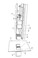
多軸レセプタクルCN1は、コネクタ本体15と、カバー部材16と、開口61aと、レセプタクルシェル(コネクタシェル)71とを有する。すなわちロボットコントローラ1は、コネクタ本体15と、カバー部材16と、開口61aと、レセプタクルシェル71とを備える。
コネクタ本体15は、基板11Aに設けられている。より具体的に、コネクタ本体15は、基板11A上の後側に固定され、基板11Aの後側の縁11aから後方に突出している。コネクタ本体15は樹脂からなり、後方に開口した直方体状の外形を呈する。コネクタ本体15の内部は、前後方向に沿う複数のセル17に区画されている。コネクタ本体15の外周側のセル17Aには、電力供給用の電力端子Tpが収容されている。セル17Aに囲まれるセル17Bには、信号伝送用の信号端子Tsが収容されている(図5参照)。詳細な図示は省略するが、電力端子Tp及び信号端子Tsは、基板11A上の配線により駆動素子等に接続されている。
カバー部材16は、銅やアルミ等の金属製の薄板であり、逆さU字の断面形状を呈してコネクタ本体15の上面及び左右の側面を覆う。すなわちカバー部材16は、コネクタ本体15の外周の少なくとも一部を覆うように設けられている。カバー部材16の後側の縁16dは、コネクタ本体15の後側の端面15aから後方に張り出している(図4参照)。
カバー部材16の左右の下端部には、基板11Aの下方に突出する脚部16aが設けられ、脚部16aの下端部には左右方向の外側に張り出す接続片16bが設けられている。コネクタ本体15の下方において、放熱板13は基板11Aの後側の縁11aから後方に張り出しており、接続片16bは放熱板13の上面に接している。接続片16bには、固定孔16cが形成されている。固定孔16cには、例えば固定用のビス(不図示)が挿通される。このビスを放熱板13に固定することにより、接続片16bが放熱板13に固定される。
開口61aは、コネクタ本体15に対応する位置において背面板61に設けられ、コネクタ本体15を外部に露出させる。開口61aは、コネクタ本体15の背面形状に対応する矩形状である。
レセプタクルシェル71は、保持部71Aとシェル本体71Bとを有し、開口61aの周縁部に装着される。レセプタクルシェル71は、後述するコネクタ本体15の温度上昇を抑制するために金属製であることが望ましい。保持部71Aは、背面板61に平行な板状体であり、背面板61の外面に装着される。保持部71Aには、後方に開口する凹部71aが形成されている。凹部71aの底部の左側部分及び右側部分には、一対のガイド突起71bがそれぞれ設けられている。ガイド突起71bは、上下方向に沿うと共に後方に突出した板状を呈する。ガイド突起71bは、後方に突出した棒状を呈するものであってもよい。
ガイド突起71b同士の間には、開口61aに対応する開口71cが形成されている。保持部71Aのうち、凹部71a外の左右には、一対の取付孔71dがそれぞれ形成されている。取付孔71dは、縦長の楕円形状を呈する。取付孔71dには、例えばビスが挿通される。このビスを背面板61に固定することにより、保持部71Aが背面板61に取り付けられる。ビスは、保持部71Aを完全に締め付けない状態で背面板61に固定される。これにより、レセプタクルシェル71は開口61aに対する筐体60の背面に沿ったガタつきをもって背面板61に取り付けられる。上述したように取付孔71dは縦長の楕円形状を呈するので、左右方向のガタつき幅に比べ上下方向のガタつき幅が大きい。
シェル本体71Bは、開口71cの上縁部及び左右の側縁部から前方に突出し、逆さU字の断面形状を呈する。シェル本体71Bの内周面の前側部分には、前方(基板11A側)に向かうに従って外側に広がるように案内面71eが形成されている(図6参照)。
シェル本体71Bを背面板61の外側から開口61aに通し、保持部71Aを背面板61に取り付けることで、開口61aの周縁部にレセプタクルシェル71が設けられる。シェル本体71Bは筐体60内に位置し、コネクタ本体15の上面及び左右の側面を囲む。コネクタ本体15の外周にはカバー部材16が設けられているので、コネクタ本体15とシェル本体71Bとの間にカバー部材16が介在する。
多軸レセプタクルCN1には、外部ケーブル5の端部に設けられたプラグ80が接続される。プラグ80は、コネクタ本体82と、プラグシェル81と、プラグカバー83とを有する。
コネクタ本体82は、コネクタ本体15の複数のセル17にそれぞれ挿入される複数の筒状部84を有する。各筒状部84には、外部ケーブル5に接続された端子(不図示)が収容されている。コネクタ本体82の外周側に配置された筒状部84Aの端子は、セル17Aの電力端子Tpに接続される。筒状部84Aに囲まれる筒状部84Bの端子は、セル17Bの信号端子Tsに接続される。
プラグシェル81は、外部ケーブル5の外周に設けられると共に前方に開口した収容器であり、コネクタ本体82を収容する。プラグカバー83は、プラグシェル81の開口を部分的に塞いでコネクタ本体82をプラグシェル81内に保持する蓋部材である。
プラグカバー83の中央には、コネクタ本体82を前方に露出させる矩形の開口83aが形成されている。開口83aの周縁部には、前方に突出する凸部83bが全周に亘って形成されている。凸部83bは、保持部71Aの凹部71aに嵌合する。この嵌合により、保持部71Aがプラグ80を保持する。
凸部83bの左側部分及び右側部分には、ガイド突起71bを受け入れるガイド開口83cが形成されている。ガイド開口83cは、ガイド突起71bが板状であるのに対応してスリット状を呈する。ガイド突起71bが棒状を呈する場合には、ガイド開口83cは孔状を呈する。ガイド突起71bとガイド開口83cとの嵌合により、多軸レセプタクルCN1に対するプラグ80の挿入方向が前後方向に沿うように案内される。このため、筒状部84をセル17内に円滑に挿入できる。
プラグカバー83の四隅には、取付孔83dが形成されている。取付孔83dには、例えばビスが挿通される。このビスをプラグシェル81に固定することにより、プラグカバー83がプラグシェル81に取り付けられる。ビスは、プラグカバー83を完全に締め付けない状態でプラグシェル81に固定される。これにより、プラグカバー83はプラグシェル81の前側端面に沿ったガタつきをもってプラグシェル81に取り付けられる。
以上に説明したロボットコントローラ1によれば、ドライバ10の基板11Aに設けられたコネクタ本体15が、筐体60に設けられた開口61aから外部に露出するので、外部ケーブル5のプラグ80をコネクタ本体15に直接接続可能である。このため、筐体60内部において、プラグ80と基板11Aとの間にケーブルを介在させる必要がない。従って、筐体60内部のケーブルを削減できる。
ここで、制御対象と制御装置とを接続する外部配線を単純化するために、多くの端子をコネクタ本体に集約することが望ましい。例えばロボットコントローラ1においては、多関節ロボット2の全てのアクチュエータを接続するための端子がコネクタ本体15に集約されている。多くの端子がコネクタ本体15に集約されると、コネクタ本体15における発熱が大きくなる。これに対し、開口61aの周縁部にレセプタクルシェル71が設けられ、レセプタクルシェル71によりコネクタ本体15が囲まれている。更に、コネクタ本体15とレセプタクルシェル71との間に金属製のカバー部材16が介在している。これらにより、コネクタ本体15で発生した熱を筐体60に分散させ、コネクタ本体15の温度上昇を抑制できる。レセプタクルシェル71も金属製とすれば、コネクタ本体15で発生した熱を更に効率よく筐体60へ分散させることができる。このようにコネクタ本体15の温度上昇を抑制することが、コネクタ本体15にプラグ80を直接接続する構成の実現に大きく寄与している。
コネクタ本体15は、複数の電力端子Tpと、複数の信号端子Tsとを有し、複数の電力端子Tpはコネクタ本体15の外周側に配置されている。電力端子Tpは信号端子Tsに比べ発熱し易い傾向がある。このため、電力端子Tpをコネクタ本体15の外周側に配置してカバー部材16及びレセプタクルシェル71に近付けることで、コネクタ本体15で発生した熱をより効率よく筐体60に分散させることができる。従って、コネクタ本体15の温度上昇をより確実に抑制できる。
なお、電力端子Tpを収容するセル17Aと信号端子Tsを収容するセル17Bとの間に、銅やアルミ等の金属製の隔壁18を設けてもよい(図7参照)。隔壁18のシールド効果により、電力端子Tpから信号端子Tsへのノイズ伝播が抑制されるので、コネクタ本体15に多くの端子を集約させ易くなる。
カバー部材16の後側(開口61a側)の縁16dは、コネクタ本体15の後端面(開口61a側の端面)15aから張り出している。ドライバ10を筐体60内に設置するときには、筐体60内側からレセプタクルシェル71のシェル本体71Bに向かって、すなわち正面から背面の方向へとコネクタ本体15が挿入される。縁16dが端面15aから張り出した構成を採用することにより、レセプタクルシェル71にコネクタ本体15を挿入するときにコネクタ本体15の後端部を保護できる。
シェル本体71Bの内周面の前側部分(基板11A側の部分)には、案内面71eが形成されている。このため、シェル本体71Bにコネクタ本体15を円滑に挿入できる。
案内面71eを形成するのに代えて、カバー部材16の外周面の後側部分(開口61a側の部分)に、後側に向かうに従って内側に縮まるように案内面16eを形成してもよい(図8参照)。この場合も、シェル本体71Bにコネクタ本体15を円滑に挿入できる。案内面71eと案内面16eの両方を形成してもよい。
レセプタクルシェル71は、開口61aに対する筐体60の背面に沿ったガタつきをもって筐体60に取り付けられている。このため、コネクタ本体15の位置のばらつきにレセプタクルシェル71の位置を適応させることができる。これにより、レセプタクルシェル71にコネクタ本体15をより円滑に挿入できる。なお、上述したように、取付孔71dは縦長の楕円形状を呈するので、左右方向のガタつき幅に比べ上下方向のガタつき幅が大きい。このため、特に、基板11Aの厚さ方向におけるコネクタ本体15の位置のばらつきに対して、レセプタクルシェル71の位置を適応させ易い。
また、プラグカバー83はガタつきをもってプラグシェル81に取り付けられている。このため、凸部83bが凹部71aに嵌合した状態でも、コネクタ本体82は開口83aに対するガタつきをもって保持される。これにより、コネクタ本体15の位置のばらつきにコネクタ本体82の位置を適応させることができる。従って、筒状部84をセル17に更に円滑に挿入できる。
レセプタクルシェル71は、プラグ80を保持するための保持部71Aを有する。コネクタ本体15をプラグ80の接続用のコネクタとして用いる場合、交換のためにドライバ10を正面方向へと引き出して筐体60内から取り出すときに、プラグ80の接続先が存在しないこととなる。このため、ドライバ10の交換のために、プラグ80をロボットコントローラ1から取り外すことが必要となり、ドライバ10の交換作業が煩雑化する。これに対し、プラグ80を保持するための保持部71Aをレセプタクルシェル71に設けたことにより、プラグ80をロボットコントローラ1に取り付けたままドライバ10を交換できる(図9参照)。すなわち、筐体60内部のケーブルの削減と、ドライバ10の交換作業の簡素化との両立を図ることができる。
特に、ロボットコントローラ1のうち外部ケーブル5の接続部分がフェンス6内に配置されている場合、プラグ80をロボットコントローラ1から取り外すことなくドライバ10を交換できることの有効性が顕著となる。
なお、ドライバ10の交換作業におけるプラグ80の脱落をより確実に防止するために、ビス等によりプラグ80を保持部71Aに固定するロック機構を更に設けてもよい。
カバー部材16は、放熱板13に固定されている。これにより、コネクタ本体15の温度上昇をより確実に抑制できる。
以上、本発明の好適な実施形態について説明してきたが、本発明は必ずしも上述した実施形態に限定されるものではなく、その要旨を逸脱しない範囲で様々な変更が可能である。例えば、カバー部材16は、コネクタ本体15の全周を覆うものであってもよいし、コネクタ本体15の一面のみを部分的に覆うものであってもよい。レセプタクルシェル71はコネクタ本体15の全周を囲むものであってもよい。
多関節ロボット2のアクチュエータ用の多軸レセプタクルCN1と、外部軸アクチュエータ用の単軸レセプタクルCN2とを必ずしも分離しなくてよい。例えば、外部軸アクチュエータ用の端子をレセプタクルCN1に含めてもよい。
ドライバ10が制御対象とするアクチュエータの数は9軸に限られず、単軸であってもよい。
制御対象は、電気的に制御されるものであればどのようなものであってもよく、多関節ロボット2に限られない。制御対象としては、例えば、工作機械や搬送装置等が挙げられる。
本発明は、電気的に制御される機器に付帯する制御装置に利用できる。
1…ロボットコントローラ(制御装置)、10…ドライバ、11A…基板、15…コネクタ本体、15a…開口側の端面、16…カバー部材、16d…開口側の縁、60…筐体、61a…開口、71…レセプタクルシェル(コネクタシェル)、71A…保持部、71e…案内面、80…プラグ、Tp…電力端子、Ts…信号端子。
Claims (7)
- 基板を有するドライバと、
前記ドライバを収容する筐体と、
前記基板に設けられたコネクタ本体と、
前記筐体に設けられ、前記コネクタ本体を外部に露出させる開口と、
前記コネクタ本体を囲むように、前記開口の周縁部に設けられたコネクタシェルと、
前記コネクタ本体の外周の少なくとも一部を覆うように設けられ、前記コネクタ本体と前記コネクタシェルとの間に介在する金属製のカバー部材と、を備える制御装置。 - 前記コネクタ本体は、アクチュエータへの電力供給用の複数の電力端子と、信号伝送用の複数の信号端子とを有し、前記複数の電力端子は前記コネクタ本体の外周側に配置されている、請求項1記載の制御装置。
- 前記カバー部材の前記開口側の縁は、前記コネクタ本体の前記開口側の端面から張り出している、請求項1又は2記載の制御装置。
- 前記シェルの内周面のうち、前記基板側の部分には、前記基板側に向かうに従って外側に広がるように案内面が形成されている、請求項1~3のいずれか一項記載の制御装置。
- 前記カバー部材の外周面のうち、前記開口側の部分には、前記開口側に向かうに従って内側に縮まるように案内面が形成されている、請求項1~4のいずれか一項記載の制御装置。
- 前記コネクタシェルは、前記開口に対するガタつきをもって前記筐体に取り付けられている、請求項1~5のいずれか一項記載の制御装置。
- 前記コネクタシェルは、前記筐体の外側から前記コネクタ本体に接続されるプラグを保持するための保持部を有する、請求項1~6のいずれか一項記載の制御装置。
Priority Applications (2)
| Application Number | Priority Date | Filing Date | Title |
|---|---|---|---|
| JP2015519594A JP6202095B2 (ja) | 2013-05-31 | 2013-05-31 | 制御装置 |
| PCT/JP2013/065283 WO2014192158A1 (ja) | 2013-05-31 | 2013-05-31 | 制御装置 |
Applications Claiming Priority (1)
| Application Number | Priority Date | Filing Date | Title |
|---|---|---|---|
| PCT/JP2013/065283 WO2014192158A1 (ja) | 2013-05-31 | 2013-05-31 | 制御装置 |
Publications (1)
| Publication Number | Publication Date |
|---|---|
| WO2014192158A1 true WO2014192158A1 (ja) | 2014-12-04 |
Family
ID=51988226
Family Applications (1)
| Application Number | Title | Priority Date | Filing Date |
|---|---|---|---|
| PCT/JP2013/065283 Ceased WO2014192158A1 (ja) | 2013-05-31 | 2013-05-31 | 制御装置 |
Country Status (2)
| Country | Link |
|---|---|
| JP (1) | JP6202095B2 (ja) |
| WO (1) | WO2014192158A1 (ja) |
Citations (4)
| Publication number | Priority date | Publication date | Assignee | Title |
|---|---|---|---|---|
| JPS59195684U (ja) * | 1983-06-15 | 1984-12-26 | 日本電気ホームエレクトロニクス株式会社 | カプラ取付構体 |
| JPH01158678U (ja) * | 1988-04-20 | 1989-11-01 | ||
| JP2000260528A (ja) * | 1998-10-19 | 2000-09-22 | Molex Inc | シールド電気コネクタ |
| JP2005285590A (ja) * | 2004-03-30 | 2005-10-13 | Japan Aviation Electronics Industry Ltd | Emi対策型コネクタ |
-
2013
- 2013-05-31 WO PCT/JP2013/065283 patent/WO2014192158A1/ja not_active Ceased
- 2013-05-31 JP JP2015519594A patent/JP6202095B2/ja active Active
Patent Citations (4)
| Publication number | Priority date | Publication date | Assignee | Title |
|---|---|---|---|---|
| JPS59195684U (ja) * | 1983-06-15 | 1984-12-26 | 日本電気ホームエレクトロニクス株式会社 | カプラ取付構体 |
| JPH01158678U (ja) * | 1988-04-20 | 1989-11-01 | ||
| JP2000260528A (ja) * | 1998-10-19 | 2000-09-22 | Molex Inc | シールド電気コネクタ |
| JP2005285590A (ja) * | 2004-03-30 | 2005-10-13 | Japan Aviation Electronics Industry Ltd | Emi対策型コネクタ |
Also Published As
| Publication number | Publication date |
|---|---|
| JPWO2014192158A1 (ja) | 2017-02-23 |
| JP6202095B2 (ja) | 2017-09-27 |
Similar Documents
| Publication | Publication Date | Title |
|---|---|---|
| JP6998115B2 (ja) | ロボットコントローラ | |
| US20130119760A1 (en) | Electric vehicular power controller support structure and electric vehicle | |
| JP6224042B2 (ja) | 電気接続箱およびワイヤハーネス | |
| JP6673546B2 (ja) | コントローラ組立体 | |
| CN107443421B (zh) | 电机单元以及机器人 | |
| JP2015136780A (ja) | コントローラ | |
| CN106976066A (zh) | 机器人以及机器人系统 | |
| JP7470732B2 (ja) | 電子機器 | |
| JP4958988B2 (ja) | 電動圧縮機 | |
| JP2013046506A (ja) | モータモジュールユニットとアクチュエータ | |
| JP6202095B2 (ja) | 制御装置 | |
| JP2012190876A (ja) | 制御盤 | |
| JP7309213B2 (ja) | 冷却デバイスを備えた溶接電流源 | |
| JP2019022293A (ja) | 電源装置 | |
| JPWO2013073491A1 (ja) | 電気自動車のパワーコントロールユニット | |
| JP6017823B2 (ja) | ドライバ一体型モータ | |
| JP2021065016A (ja) | 制御装置およびモータ装置 | |
| JP5593296B2 (ja) | 制御装置 | |
| JP2016220360A (ja) | 電力変換装置 | |
| CN103379805A (zh) | 电子设备 | |
| JP7192004B2 (ja) | ロボットコントローラ | |
| JP7338313B2 (ja) | 車両用バッテリパック | |
| WO2016043204A1 (ja) | 電気接続箱 | |
| JP2012253096A (ja) | 電子機器 | |
| JP7169085B2 (ja) | レーザ装置 |
Legal Events
| Date | Code | Title | Description |
|---|---|---|---|
| 121 | Ep: the epo has been informed by wipo that ep was designated in this application |
Ref document number: 13885655 Country of ref document: EP Kind code of ref document: A1 |
|
| ENP | Entry into the national phase |
Ref document number: 2015519594 Country of ref document: JP Kind code of ref document: A |
|
| NENP | Non-entry into the national phase |
Ref country code: DE |
|
| 122 | Ep: pct application non-entry in european phase |
Ref document number: 13885655 Country of ref document: EP Kind code of ref document: A1 |