WO2014189122A1 - Composé, matériau électroluminescent et élément électroluminescent organique - Google Patents
Composé, matériau électroluminescent et élément électroluminescent organique Download PDFInfo
- Publication number
- WO2014189122A1 WO2014189122A1 PCT/JP2014/063638 JP2014063638W WO2014189122A1 WO 2014189122 A1 WO2014189122 A1 WO 2014189122A1 JP 2014063638 W JP2014063638 W JP 2014063638W WO 2014189122 A1 WO2014189122 A1 WO 2014189122A1
- Authority
- WO
- WIPO (PCT)
- Prior art keywords
- group
- substituted
- carbon atoms
- general formula
- substituent
- Prior art date
Links
- 150000001875 compounds Chemical class 0.000 title claims abstract description 111
- 239000000463 material Substances 0.000 title claims abstract description 94
- 125000004432 carbon atom Chemical group C* 0.000 claims description 108
- 125000001424 substituent group Chemical group 0.000 claims description 64
- 125000004435 hydrogen atom Chemical group [H]* 0.000 claims description 48
- 238000005401 electroluminescence Methods 0.000 claims description 43
- 230000003111 delayed effect Effects 0.000 claims description 33
- 125000003118 aryl group Chemical group 0.000 claims description 23
- HEDRZPFGACZZDS-UHFFFAOYSA-N Chloroform Chemical compound ClC(Cl)Cl HEDRZPFGACZZDS-UHFFFAOYSA-N 0.000 claims description 22
- 125000004093 cyano group Chemical group *C#N 0.000 claims description 21
- 125000003545 alkoxy group Chemical group 0.000 claims description 19
- 125000000217 alkyl group Chemical group 0.000 claims description 19
- 125000001072 heteroaryl group Chemical group 0.000 claims description 18
- 125000004122 cyclic group Chemical group 0.000 claims description 15
- 239000000758 substrate Substances 0.000 claims description 15
- 229910052801 chlorine Inorganic materials 0.000 claims description 10
- 125000001309 chloro group Chemical group Cl* 0.000 claims description 10
- 238000000034 method Methods 0.000 claims description 10
- 229910052731 fluorine Inorganic materials 0.000 claims description 9
- 125000001153 fluoro group Chemical group F* 0.000 claims description 9
- 229910052799 carbon Inorganic materials 0.000 claims description 8
- 125000004663 dialkyl amino group Chemical group 0.000 claims description 8
- 125000004986 diarylamino group Chemical group 0.000 claims description 8
- 125000001997 phenyl group Chemical group [H]C1=C([H])C([H])=C(*)C([H])=C1[H] 0.000 claims description 8
- OKTJSMMVPCPJKN-UHFFFAOYSA-N Carbon Chemical compound [C] OKTJSMMVPCPJKN-UHFFFAOYSA-N 0.000 claims description 6
- OAICVXFJPJFONN-UHFFFAOYSA-N Phosphorus Chemical compound [P] OAICVXFJPJFONN-UHFFFAOYSA-N 0.000 claims description 5
- 150000001721 carbon Chemical group 0.000 claims description 2
- 239000010410 layer Substances 0.000 description 150
- YXFVVABEGXRONW-UHFFFAOYSA-N Toluene Chemical compound CC1=CC=CC=C1 YXFVVABEGXRONW-UHFFFAOYSA-N 0.000 description 48
- 230000000903 blocking effect Effects 0.000 description 40
- IJGRMHOSHXDMSA-UHFFFAOYSA-N Atomic nitrogen Chemical compound N#N IJGRMHOSHXDMSA-UHFFFAOYSA-N 0.000 description 36
- 238000002347 injection Methods 0.000 description 22
- 239000007924 injection Substances 0.000 description 22
- 239000000203 mixture Substances 0.000 description 21
- 229910052757 nitrogen Inorganic materials 0.000 description 21
- 238000005424 photoluminescence Methods 0.000 description 21
- 230000005525 hole transport Effects 0.000 description 17
- 229940125904 compound 1 Drugs 0.000 description 16
- 238000003786 synthesis reaction Methods 0.000 description 16
- 230000015572 biosynthetic process Effects 0.000 description 15
- 229940125782 compound 2 Drugs 0.000 description 12
- VLKZOEOYAKHREP-UHFFFAOYSA-N n-Hexane Chemical compound CCCCCC VLKZOEOYAKHREP-UHFFFAOYSA-N 0.000 description 12
- 239000012044 organic layer Substances 0.000 description 12
- 229920000642 polymer Polymers 0.000 description 12
- BWHMMNNQKKPAPP-UHFFFAOYSA-L potassium carbonate Chemical compound [K+].[K+].[O-]C([O-])=O BWHMMNNQKKPAPP-UHFFFAOYSA-L 0.000 description 10
- BWHDROKFUHTORW-UHFFFAOYSA-N tritert-butylphosphane Chemical compound CC(C)(C)P(C(C)(C)C)C(C)(C)C BWHDROKFUHTORW-UHFFFAOYSA-N 0.000 description 10
- 238000006243 chemical reaction Methods 0.000 description 9
- 239000010409 thin film Substances 0.000 description 9
- FYYHWMGAXLPEAU-UHFFFAOYSA-N Magnesium Chemical compound [Mg] FYYHWMGAXLPEAU-UHFFFAOYSA-N 0.000 description 8
- 229910052782 aluminium Inorganic materials 0.000 description 8
- XAGFODPZIPBFFR-UHFFFAOYSA-N aluminium Chemical compound [Al] XAGFODPZIPBFFR-UHFFFAOYSA-N 0.000 description 8
- 239000011777 magnesium Substances 0.000 description 8
- 229910052749 magnesium Inorganic materials 0.000 description 8
- 238000005259 measurement Methods 0.000 description 8
- 239000007787 solid Substances 0.000 description 8
- 230000001052 transient effect Effects 0.000 description 8
- 239000007772 electrode material Substances 0.000 description 7
- 238000000295 emission spectrum Methods 0.000 description 7
- 230000005284 excitation Effects 0.000 description 7
- 238000004020 luminiscence type Methods 0.000 description 7
- 229910052751 metal Inorganic materials 0.000 description 7
- 239000002184 metal Substances 0.000 description 7
- 239000000243 solution Substances 0.000 description 7
- 125000005843 halogen group Chemical group 0.000 description 6
- -1 isopropyloxy group Chemical group 0.000 description 6
- 125000005647 linker group Chemical group 0.000 description 6
- 125000001791 phenazinyl group Chemical group C1(=CC=CC2=NC3=CC=CC=C3N=C12)* 0.000 description 6
- 238000001296 phosphorescence spectrum Methods 0.000 description 6
- IVURTNNWJAPOML-UHFFFAOYSA-N 5,10-dihydrophenazine Chemical compound C1=CC=C2NC3=CC=CC=C3NC2=C1 IVURTNNWJAPOML-UHFFFAOYSA-N 0.000 description 5
- 0 Cc(cccc1)c1-c1nc(CC=CC=CC#*)nc(C)n1 Chemical compound Cc(cccc1)c1-c1nc(CC=CC=CC#*)nc(C)n1 0.000 description 5
- CSNNHWWHGAXBCP-UHFFFAOYSA-L Magnesium sulfate Chemical compound [Mg+2].[O-][S+2]([O-])([O-])[O-] CSNNHWWHGAXBCP-UHFFFAOYSA-L 0.000 description 5
- 239000012267 brine Substances 0.000 description 5
- 230000005587 bubbling Effects 0.000 description 5
- 238000001816 cooling Methods 0.000 description 5
- 230000018044 dehydration Effects 0.000 description 5
- 238000006297 dehydration reaction Methods 0.000 description 5
- 239000010408 film Substances 0.000 description 5
- 239000011259 mixed solution Substances 0.000 description 5
- 239000000178 monomer Substances 0.000 description 5
- LXNAVEXFUKBNMK-UHFFFAOYSA-N palladium(II) acetate Substances [Pd].CC(O)=O.CC(O)=O LXNAVEXFUKBNMK-UHFFFAOYSA-N 0.000 description 5
- YJVFFLUZDVXJQI-UHFFFAOYSA-L palladium(ii) acetate Chemical compound [Pd+2].CC([O-])=O.CC([O-])=O YJVFFLUZDVXJQI-UHFFFAOYSA-L 0.000 description 5
- 229910000027 potassium carbonate Inorganic materials 0.000 description 5
- HPALAKNZSZLMCH-UHFFFAOYSA-M sodium;chloride;hydrate Chemical compound O.[Na+].[Cl-] HPALAKNZSZLMCH-UHFFFAOYSA-M 0.000 description 5
- 239000002904 solvent Substances 0.000 description 5
- 238000007740 vapor deposition Methods 0.000 description 5
- 229940125898 compound 5 Drugs 0.000 description 4
- 238000000921 elemental analysis Methods 0.000 description 4
- 238000011156 evaluation Methods 0.000 description 4
- 125000005842 heteroatom Chemical group 0.000 description 4
- 238000001906 matrix-assisted laser desorption--ionisation mass spectrometry Methods 0.000 description 4
- 150000002894 organic compounds Chemical class 0.000 description 4
- 125000004430 oxygen atom Chemical group O* 0.000 description 4
- 230000000379 polymerizing effect Effects 0.000 description 4
- 238000005215 recombination Methods 0.000 description 4
- 230000006798 recombination Effects 0.000 description 4
- 230000000630 rising effect Effects 0.000 description 4
- 125000004665 trialkylsilyl group Chemical group 0.000 description 4
- WHXSMMKQMYFTQS-UHFFFAOYSA-N Lithium Chemical compound [Li] WHXSMMKQMYFTQS-UHFFFAOYSA-N 0.000 description 3
- 125000003342 alkenyl group Chemical group 0.000 description 3
- 125000000304 alkynyl group Chemical group 0.000 description 3
- 125000000609 carbazolyl group Chemical group C1(=CC=CC=2C3=CC=CC=C3NC12)* 0.000 description 3
- 238000000576 coating method Methods 0.000 description 3
- 238000002189 fluorescence spectrum Methods 0.000 description 3
- 125000002887 hydroxy group Chemical group [H]O* 0.000 description 3
- 229910052738 indium Inorganic materials 0.000 description 3
- APFVFJFRJDLVQX-UHFFFAOYSA-N indium atom Chemical compound [In] APFVFJFRJDLVQX-UHFFFAOYSA-N 0.000 description 3
- 229910052744 lithium Inorganic materials 0.000 description 3
- 125000004433 nitrogen atom Chemical group N* 0.000 description 3
- 150000004866 oxadiazoles Chemical class 0.000 description 3
- 238000002360 preparation method Methods 0.000 description 3
- 238000001228 spectrum Methods 0.000 description 3
- 238000004544 sputter deposition Methods 0.000 description 3
- 229910052717 sulfur Inorganic materials 0.000 description 3
- 125000004434 sulfur atom Chemical group 0.000 description 3
- JYEUMXHLPRZUAT-UHFFFAOYSA-N 1,2,3-triazine Chemical group C1=CN=NN=C1 JYEUMXHLPRZUAT-UHFFFAOYSA-N 0.000 description 2
- 125000000355 1,3-benzoxazolyl group Chemical group O1C(=NC2=C1C=CC=C2)* 0.000 description 2
- ZCYVEMRRCGMTRW-UHFFFAOYSA-N 7553-56-2 Chemical group [I] ZCYVEMRRCGMTRW-UHFFFAOYSA-N 0.000 description 2
- 229910018072 Al 2 O 3 Inorganic materials 0.000 description 2
- WKBOTKDWSSQWDR-UHFFFAOYSA-N Bromine atom Chemical group [Br] WKBOTKDWSSQWDR-UHFFFAOYSA-N 0.000 description 2
- XUIMIQQOPSSXEZ-UHFFFAOYSA-N Silicon Chemical compound [Si] XUIMIQQOPSSXEZ-UHFFFAOYSA-N 0.000 description 2
- BQCADISMDOOEFD-UHFFFAOYSA-N Silver Chemical compound [Ag] BQCADISMDOOEFD-UHFFFAOYSA-N 0.000 description 2
- PPBRXRYQALVLMV-UHFFFAOYSA-N Styrene Chemical compound C=CC1=CC=CC=C1 PPBRXRYQALVLMV-UHFFFAOYSA-N 0.000 description 2
- YTPLMLYBLZKORZ-UHFFFAOYSA-N Thiophene Chemical compound C=1C=CSC=1 YTPLMLYBLZKORZ-UHFFFAOYSA-N 0.000 description 2
- 238000010521 absorption reaction Methods 0.000 description 2
- 125000002723 alicyclic group Chemical group 0.000 description 2
- 125000004414 alkyl thio group Chemical group 0.000 description 2
- 125000002947 alkylene group Chemical group 0.000 description 2
- 229910045601 alloy Inorganic materials 0.000 description 2
- 239000000956 alloy Substances 0.000 description 2
- 125000003277 amino group Chemical class 0.000 description 2
- IOJUPLGTWVMSFF-UHFFFAOYSA-N benzothiazole Chemical group C1=CC=C2SC=NC2=C1 IOJUPLGTWVMSFF-UHFFFAOYSA-N 0.000 description 2
- 230000000052 comparative effect Effects 0.000 description 2
- 239000011521 glass Substances 0.000 description 2
- 125000001188 haloalkyl group Chemical group 0.000 description 2
- AMGQUBHHOARCQH-UHFFFAOYSA-N indium;oxotin Chemical compound [In].[Sn]=O AMGQUBHHOARCQH-UHFFFAOYSA-N 0.000 description 2
- 229910052740 iodine Inorganic materials 0.000 description 2
- 125000001624 naphthyl group Chemical group 0.000 description 2
- 230000003287 optical effect Effects 0.000 description 2
- TWNQGVIAIRXVLR-UHFFFAOYSA-N oxo(oxoalumanyloxy)alumane Chemical compound O=[Al]O[Al]=O TWNQGVIAIRXVLR-UHFFFAOYSA-N 0.000 description 2
- 238000012545 processing Methods 0.000 description 2
- 125000000714 pyrimidinyl group Chemical group 0.000 description 2
- 238000006862 quantum yield reaction Methods 0.000 description 2
- 125000001567 quinoxalinyl group Chemical class N1=C(C=NC2=CC=CC=C12)* 0.000 description 2
- 229910052710 silicon Inorganic materials 0.000 description 2
- 239000010703 silicon Substances 0.000 description 2
- 229910052709 silver Inorganic materials 0.000 description 2
- 239000004332 silver Substances 0.000 description 2
- 239000002356 single layer Substances 0.000 description 2
- 238000001308 synthesis method Methods 0.000 description 2
- 239000012780 transparent material Substances 0.000 description 2
- 238000001771 vacuum deposition Methods 0.000 description 2
- GWYPDXLJACEENP-UHFFFAOYSA-N 1,3-cycloheptadiene Chemical group C1CC=CC=CC1 GWYPDXLJACEENP-UHFFFAOYSA-N 0.000 description 1
- VERMWGQSKPXSPZ-BUHFOSPRSA-N 1-[(e)-2-phenylethenyl]anthracene Chemical class C=1C=CC2=CC3=CC=CC=C3C=C2C=1\C=C\C1=CC=CC=C1 VERMWGQSKPXSPZ-BUHFOSPRSA-N 0.000 description 1
- MVWPVABZQQJTPL-UHFFFAOYSA-N 2,3-diphenylcyclohexa-2,5-diene-1,4-dione Chemical class O=C1C=CC(=O)C(C=2C=CC=CC=2)=C1C1=CC=CC=C1 MVWPVABZQQJTPL-UHFFFAOYSA-N 0.000 description 1
- FQIRBKKYMJKENC-UHFFFAOYSA-N 2-(4-bromophenyl)-1,3-benzothiazole Chemical compound C1=CC(Br)=CC=C1C1=NC2=CC=CC=C2S1 FQIRBKKYMJKENC-UHFFFAOYSA-N 0.000 description 1
- DXRLALXPCIOIDK-UHFFFAOYSA-N 2-(4-bromophenyl)-1-phenylbenzimidazole Chemical compound C1=CC(Br)=CC=C1C1=NC2=CC=CC=C2N1C1=CC=CC=C1 DXRLALXPCIOIDK-UHFFFAOYSA-N 0.000 description 1
- AYHGAQGOMUQMTR-UHFFFAOYSA-N 2-(4-bromophenyl)-4,6-diphenyl-1,3,5-triazine Chemical compound C1=CC(Br)=CC=C1C1=NC(C=2C=CC=CC=2)=NC(C=2C=CC=CC=2)=N1 AYHGAQGOMUQMTR-UHFFFAOYSA-N 0.000 description 1
- NKIUXMAXCJIOEK-UHFFFAOYSA-N 2-[4-[10-[4-(1,3-benzothiazol-2-yl)phenyl]phenazin-5-yl]phenyl]-1,3-benzothiazole Chemical compound S1C2=CC=CC=C2N=C1C1=CC=C(C=C1)N1C2=C(C=CC=C2)N(C2=CC=C(C=C2)C2=NC3=CC=CC=C3S2)C2=C1C=CC=C2 NKIUXMAXCJIOEK-UHFFFAOYSA-N 0.000 description 1
- SCIZMEBVJHCDJO-UHFFFAOYSA-N 3-[10-(3-cyanophenyl)phenazin-5-yl]benzonitrile Chemical compound N#Cc1cccc(c1)N1c2ccccc2N(c2cccc(c2)C#N)c2ccccc12 SCIZMEBVJHCDJO-UHFFFAOYSA-N 0.000 description 1
- STXAVEHFKAXGOX-UHFFFAOYSA-N 3-bromobenzonitrile Chemical compound BrC1=CC=CC(C#N)=C1 STXAVEHFKAXGOX-UHFFFAOYSA-N 0.000 description 1
- WDBQJSCPCGTAFG-QHCPKHFHSA-N 4,4-difluoro-N-[(1S)-3-[4-(3-methyl-5-propan-2-yl-1,2,4-triazol-4-yl)piperidin-1-yl]-1-pyridin-3-ylpropyl]cyclohexane-1-carboxamide Chemical compound FC1(CCC(CC1)C(=O)N[C@@H](CCN1CCC(CC1)N1C(=NN=C1C)C(C)C)C=1C=NC=CC=1)F WDBQJSCPCGTAFG-QHCPKHFHSA-N 0.000 description 1
- BWGRDBSNKQABCB-UHFFFAOYSA-N 4,4-difluoro-N-[3-[3-(3-methyl-5-propan-2-yl-1,2,4-triazol-4-yl)-8-azabicyclo[3.2.1]octan-8-yl]-1-thiophen-2-ylpropyl]cyclohexane-1-carboxamide Chemical compound CC(C)C1=NN=C(C)N1C1CC2CCC(C1)N2CCC(NC(=O)C1CCC(F)(F)CC1)C1=CC=CS1 BWGRDBSNKQABCB-UHFFFAOYSA-N 0.000 description 1
- XXWKRDLSZRRJDX-UHFFFAOYSA-N 4-[10-(4-cyanophenyl)phenazin-5-yl]benzonitrile Chemical compound C(#N)C1=CC=C(C=C1)N1C=2C=CC=CC=2N(C2=CC=CC=C12)C1=CC=C(C=C1)C#N XXWKRDLSZRRJDX-UHFFFAOYSA-N 0.000 description 1
- HQSCPPCMBMFJJN-UHFFFAOYSA-N 4-bromobenzonitrile Chemical compound BrC1=CC=C(C#N)C=C1 HQSCPPCMBMFJJN-UHFFFAOYSA-N 0.000 description 1
- ZYASLTYCYTYKFC-UHFFFAOYSA-N 9-methylidenefluorene Chemical class C1=CC=C2C(=C)C3=CC=CC=C3C2=C1 ZYASLTYCYTYKFC-UHFFFAOYSA-N 0.000 description 1
- SWFPHKYNGKIRCX-UHFFFAOYSA-N Cc(c(C)c1)ccc1-c1nc(cccc2)c2[n]1-c1ccccc1 Chemical compound Cc(c(C)c1)ccc1-c1nc(cccc2)c2[n]1-c1ccccc1 SWFPHKYNGKIRCX-UHFFFAOYSA-N 0.000 description 1
- UTMZWCTVPHAOJZ-UHFFFAOYSA-N Cc(cc1)ccc1-c1nc(cccc2)c2[o]1 Chemical compound Cc(cc1)ccc1-c1nc(cccc2)c2[o]1 UTMZWCTVPHAOJZ-UHFFFAOYSA-N 0.000 description 1
- VCZNNAKNUVJVGX-UHFFFAOYSA-N Cc(cc1)ccc1C#N Chemical compound Cc(cc1)ccc1C#N VCZNNAKNUVJVGX-UHFFFAOYSA-N 0.000 description 1
- RYGMFSIKBFXOCR-UHFFFAOYSA-N Copper Chemical compound [Cu] RYGMFSIKBFXOCR-UHFFFAOYSA-N 0.000 description 1
- YZCKVEUIGOORGS-OUBTZVSYSA-N Deuterium Chemical compound [2H] YZCKVEUIGOORGS-OUBTZVSYSA-N 0.000 description 1
- VGGSQFUCUMXWEO-UHFFFAOYSA-N Ethene Chemical compound C=C VGGSQFUCUMXWEO-UHFFFAOYSA-N 0.000 description 1
- 239000005977 Ethylene Substances 0.000 description 1
- DGAQECJNVWCQMB-PUAWFVPOSA-M Ilexoside XXIX Chemical compound C[C@@H]1CC[C@@]2(CC[C@@]3(C(=CC[C@H]4[C@]3(CC[C@@H]5[C@@]4(CC[C@@H](C5(C)C)OS(=O)(=O)[O-])C)C)[C@@H]2[C@]1(C)O)C)C(=O)O[C@H]6[C@@H]([C@H]([C@@H]([C@H](O6)CO)O)O)O.[Na+] DGAQECJNVWCQMB-PUAWFVPOSA-M 0.000 description 1
- 229910000799 K alloy Inorganic materials 0.000 description 1
- LFZAGIJXANFPFN-UHFFFAOYSA-N N-[3-[4-(3-methyl-5-propan-2-yl-1,2,4-triazol-4-yl)piperidin-1-yl]-1-thiophen-2-ylpropyl]acetamide Chemical compound C(C)(C)C1=NN=C(N1C1CCN(CC1)CCC(C=1SC=CC=1)NC(C)=O)C LFZAGIJXANFPFN-UHFFFAOYSA-N 0.000 description 1
- PAYRUJLWNCNPSJ-UHFFFAOYSA-N N-phenyl amine Natural products NC1=CC=CC=C1 PAYRUJLWNCNPSJ-UHFFFAOYSA-N 0.000 description 1
- JUJWROOIHBZHMG-UHFFFAOYSA-N Pyridine Chemical group C1=CC=NC=C1 JUJWROOIHBZHMG-UHFFFAOYSA-N 0.000 description 1
- 229910006404 SnO 2 Inorganic materials 0.000 description 1
- FZWLAAWBMGSTSO-UHFFFAOYSA-N Thiazole Chemical compound C1=CSC=N1 FZWLAAWBMGSTSO-UHFFFAOYSA-N 0.000 description 1
- 125000002252 acyl group Chemical group 0.000 description 1
- 125000004453 alkoxycarbonyl group Chemical group 0.000 description 1
- 125000004390 alkyl sulfonyl group Chemical group 0.000 description 1
- 125000003368 amide group Chemical group 0.000 description 1
- 150000008425 anthrones Chemical class 0.000 description 1
- 150000004982 aromatic amines Chemical class 0.000 description 1
- 125000000732 arylene group Chemical group 0.000 description 1
- 125000004429 atom Chemical group 0.000 description 1
- 230000004888 barrier function Effects 0.000 description 1
- 125000003354 benzotriazolyl group Chemical group N1N=NC2=C1C=CC=C2* 0.000 description 1
- 125000004106 butoxy group Chemical group [*]OC([H])([H])C([H])([H])C(C([H])([H])[H])([H])[H] 0.000 description 1
- 125000000484 butyl group Chemical group [H]C([*])([H])C([H])([H])C([H])([H])C([H])([H])[H] 0.000 description 1
- 150000001718 carbodiimides Chemical class 0.000 description 1
- 239000000969 carrier Substances 0.000 description 1
- 239000011248 coating agent Substances 0.000 description 1
- 229940126214 compound 3 Drugs 0.000 description 1
- 229920001940 conductive polymer Polymers 0.000 description 1
- 239000000470 constituent Substances 0.000 description 1
- 229920001577 copolymer Polymers 0.000 description 1
- 238000007334 copolymerization reaction Methods 0.000 description 1
- 229910052802 copper Inorganic materials 0.000 description 1
- 239000010949 copper Substances 0.000 description 1
- CHVJITGCYZJHLR-UHFFFAOYSA-N cyclohepta-1,3,5-triene Chemical group C1C=CC=CC=C1 CHVJITGCYZJHLR-UHFFFAOYSA-N 0.000 description 1
- ZXIJMRYMVAMXQP-UHFFFAOYSA-N cycloheptene Chemical group C1CCC=CCC1 ZXIJMRYMVAMXQP-UHFFFAOYSA-N 0.000 description 1
- MGNZXYYWBUKAII-UHFFFAOYSA-N cyclohexa-1,3-diene Chemical group C1CC=CC=C1 MGNZXYYWBUKAII-UHFFFAOYSA-N 0.000 description 1
- 125000000596 cyclohexenyl group Chemical group C1(=CCCCC1)* 0.000 description 1
- LPIQUOYDBNQMRZ-UHFFFAOYSA-N cyclopentene Chemical group C1CC=CC1 LPIQUOYDBNQMRZ-UHFFFAOYSA-N 0.000 description 1
- 238000000151 deposition Methods 0.000 description 1
- 230000008021 deposition Effects 0.000 description 1
- 229910052805 deuterium Inorganic materials 0.000 description 1
- 238000009792 diffusion process Methods 0.000 description 1
- 239000000539 dimer Substances 0.000 description 1
- 239000002019 doping agent Substances 0.000 description 1
- 238000001035 drying Methods 0.000 description 1
- 230000000694 effects Effects 0.000 description 1
- 230000005684 electric field Effects 0.000 description 1
- 125000006575 electron-withdrawing group Chemical group 0.000 description 1
- 238000005516 engineering process Methods 0.000 description 1
- 125000001301 ethoxy group Chemical group [H]C([H])([H])C([H])([H])O* 0.000 description 1
- 125000001495 ethyl group Chemical group [H]C([H])([H])C([H])([H])* 0.000 description 1
- 238000001704 evaporation Methods 0.000 description 1
- 230000005281 excited state Effects 0.000 description 1
- 150000008376 fluorenones Chemical class 0.000 description 1
- 125000000524 functional group Chemical group 0.000 description 1
- 230000009477 glass transition Effects 0.000 description 1
- 125000000623 heterocyclic group Chemical group 0.000 description 1
- 125000004051 hexyl group Chemical group [H]C([H])([H])C([H])([H])C([H])([H])C([H])([H])C([H])([H])C([H])([H])* 0.000 description 1
- 125000003707 hexyloxy group Chemical group [H]C([H])([H])C([H])([H])C([H])([H])C([H])([H])C([H])([H])C([H])([H])O* 0.000 description 1
- 229940083761 high-ceiling diuretics pyrazolone derivative Drugs 0.000 description 1
- 238000004770 highest occupied molecular orbital Methods 0.000 description 1
- 150000007857 hydrazones Chemical class 0.000 description 1
- 238000005286 illumination Methods 0.000 description 1
- 150000002460 imidazoles Chemical class 0.000 description 1
- 125000002636 imidazolinyl group Chemical group 0.000 description 1
- 125000002883 imidazolyl group Chemical group 0.000 description 1
- 230000006872 improvement Effects 0.000 description 1
- VVVPGLRKXQSQSZ-UHFFFAOYSA-N indolo[3,2-c]carbazole Chemical class C1=CC=CC2=NC3=C4C5=CC=CC=C5N=C4C=CC3=C21 VVVPGLRKXQSQSZ-UHFFFAOYSA-N 0.000 description 1
- 230000003993 interaction Effects 0.000 description 1
- 229940079865 intestinal antiinfectives imidazole derivative Drugs 0.000 description 1
- 238000011835 investigation Methods 0.000 description 1
- 125000001449 isopropyl group Chemical group [H]C([H])([H])C([H])(*)C([H])([H])[H] 0.000 description 1
- ZLTPDFXIESTBQG-UHFFFAOYSA-N isothiazole Chemical group C=1C=NSC=1 ZLTPDFXIESTBQG-UHFFFAOYSA-N 0.000 description 1
- 125000000842 isoxazolyl group Chemical group 0.000 description 1
- 238000003475 lamination Methods 0.000 description 1
- PQXKHYXIUOZZFA-UHFFFAOYSA-M lithium fluoride Chemical compound [Li+].[F-] PQXKHYXIUOZZFA-UHFFFAOYSA-M 0.000 description 1
- 238000004768 lowest unoccupied molecular orbital Methods 0.000 description 1
- 238000004519 manufacturing process Methods 0.000 description 1
- 239000011159 matrix material Substances 0.000 description 1
- 230000007246 mechanism Effects 0.000 description 1
- 150000002739 metals Chemical class 0.000 description 1
- 125000000956 methoxy group Chemical group [H]C([H])([H])O* 0.000 description 1
- 125000002496 methyl group Chemical group [H]C([H])([H])* 0.000 description 1
- IBHBKWKFFTZAHE-UHFFFAOYSA-N n-[4-[4-(n-naphthalen-1-ylanilino)phenyl]phenyl]-n-phenylnaphthalen-1-amine Chemical compound C1=CC=CC=C1N(C=1C2=CC=CC=C2C=CC=1)C1=CC=C(C=2C=CC(=CC=2)N(C=2C=CC=CC=2)C=2C3=CC=CC=C3C=CC=2)C=C1 IBHBKWKFFTZAHE-UHFFFAOYSA-N 0.000 description 1
- 125000000449 nitro group Chemical group [O-][N+](*)=O 0.000 description 1
- WCPAKWJPBJAGKN-UHFFFAOYSA-N oxadiazole Chemical group C1=CON=N1 WCPAKWJPBJAGKN-UHFFFAOYSA-N 0.000 description 1
- AICOOMRHRUFYCM-ZRRPKQBOSA-N oxazine, 1 Chemical compound C([C@@H]1[C@H](C(C[C@]2(C)[C@@H]([C@H](C)N(C)C)[C@H](O)C[C@]21C)=O)CC1=CC2)C[C@H]1[C@@]1(C)[C@H]2N=C(C(C)C)OC1 AICOOMRHRUFYCM-ZRRPKQBOSA-N 0.000 description 1
- 150000007978 oxazole derivatives Chemical class 0.000 description 1
- 125000002971 oxazolyl group Chemical group 0.000 description 1
- 230000003647 oxidation Effects 0.000 description 1
- 238000007254 oxidation reaction Methods 0.000 description 1
- 125000004115 pentoxy group Chemical group [*]OC([H])([H])C([H])([H])C([H])([H])C(C([H])([H])[H])([H])[H] 0.000 description 1
- 125000001147 pentyl group Chemical group C(CCCC)* 0.000 description 1
- 125000000843 phenylene group Chemical group C1(=C(C=CC=C1)*)* 0.000 description 1
- 150000004986 phenylenediamines Chemical class 0.000 description 1
- 238000000206 photolithography Methods 0.000 description 1
- 229920003023 plastic Polymers 0.000 description 1
- 239000002861 polymer material Substances 0.000 description 1
- BITYAPCSNKJESK-UHFFFAOYSA-N potassiosodium Chemical compound [Na].[K] BITYAPCSNKJESK-UHFFFAOYSA-N 0.000 description 1
- 230000008569 process Effects 0.000 description 1
- 125000002572 propoxy group Chemical group [*]OC([H])([H])C(C([H])([H])[H])([H])[H] 0.000 description 1
- 125000001436 propyl group Chemical group [H]C([*])([H])C([H])([H])C([H])([H])[H] 0.000 description 1
- 125000003373 pyrazinyl group Chemical group 0.000 description 1
- JEXVQSWXXUJEMA-UHFFFAOYSA-N pyrazol-3-one Chemical class O=C1C=CN=N1 JEXVQSWXXUJEMA-UHFFFAOYSA-N 0.000 description 1
- 150000003219 pyrazolines Chemical class 0.000 description 1
- 125000003226 pyrazolyl group Chemical group 0.000 description 1
- PBMFSQRYOILNGV-UHFFFAOYSA-N pyridazine Chemical group C1=CC=NN=C1 PBMFSQRYOILNGV-UHFFFAOYSA-N 0.000 description 1
- 125000005495 pyridazyl group Chemical group 0.000 description 1
- 125000004076 pyridyl group Chemical group 0.000 description 1
- 125000000168 pyrrolyl group Chemical group 0.000 description 1
- 239000010453 quartz Substances 0.000 description 1
- 229910052761 rare earth metal Inorganic materials 0.000 description 1
- 150000002910 rare earth metals Chemical class 0.000 description 1
- 238000011160 research Methods 0.000 description 1
- 239000004065 semiconductor Substances 0.000 description 1
- 238000010898 silica gel chromatography Methods 0.000 description 1
- VYPSYNLAJGMNEJ-UHFFFAOYSA-N silicon dioxide Inorganic materials O=[Si]=O VYPSYNLAJGMNEJ-UHFFFAOYSA-N 0.000 description 1
- 239000011734 sodium Substances 0.000 description 1
- 229910052708 sodium Inorganic materials 0.000 description 1
- 230000000087 stabilizing effect Effects 0.000 description 1
- PJANXHGTPQOBST-UHFFFAOYSA-N stilbene Chemical class C=1C=CC=CC=1C=CC1=CC=CC=C1 PJANXHGTPQOBST-UHFFFAOYSA-N 0.000 description 1
- 230000002194 synthesizing effect Effects 0.000 description 1
- 229940042055 systemic antimycotics triazole derivative Drugs 0.000 description 1
- 125000004213 tert-butoxy group Chemical group [H]C([H])([H])C(O*)(C([H])([H])[H])C([H])([H])[H] 0.000 description 1
- 125000000999 tert-butyl group Chemical group [H]C([H])([H])C(*)(C([H])([H])[H])C([H])([H])[H] 0.000 description 1
- 150000004867 thiadiazoles Chemical class 0.000 description 1
- 229930192474 thiophene Natural products 0.000 description 1
- IBBLKSWSCDAPIF-UHFFFAOYSA-N thiopyran Chemical compound S1C=CC=C=C1 IBBLKSWSCDAPIF-UHFFFAOYSA-N 0.000 description 1
- 238000012546 transfer Methods 0.000 description 1
- 230000007704 transition Effects 0.000 description 1
- 238000002834 transmittance Methods 0.000 description 1
- 150000003852 triazoles Chemical group 0.000 description 1
- 125000001425 triazolyl group Chemical group 0.000 description 1
- 239000013638 trimer Substances 0.000 description 1
Images


Classifications
-
- C—CHEMISTRY; METALLURGY
- C07—ORGANIC CHEMISTRY
- C07D—HETEROCYCLIC COMPOUNDS
- C07D241/00—Heterocyclic compounds containing 1,4-diazine or hydrogenated 1,4-diazine rings
- C07D241/36—Heterocyclic compounds containing 1,4-diazine or hydrogenated 1,4-diazine rings condensed with carbocyclic rings or ring systems
- C07D241/38—Heterocyclic compounds containing 1,4-diazine or hydrogenated 1,4-diazine rings condensed with carbocyclic rings or ring systems with only hydrogen or carbon atoms directly attached to the ring nitrogen atoms
- C07D241/46—Phenazines
- C07D241/48—Phenazines with hydrocarbon radicals, substituted by nitrogen atoms, directly attached to the ring nitrogen atoms
-
- C—CHEMISTRY; METALLURGY
- C07—ORGANIC CHEMISTRY
- C07D—HETEROCYCLIC COMPOUNDS
- C07D403/00—Heterocyclic compounds containing two or more hetero rings, having nitrogen atoms as the only ring hetero atoms, not provided for by group C07D401/00
- C07D403/14—Heterocyclic compounds containing two or more hetero rings, having nitrogen atoms as the only ring hetero atoms, not provided for by group C07D401/00 containing three or more hetero rings
-
- C—CHEMISTRY; METALLURGY
- C07—ORGANIC CHEMISTRY
- C07D—HETEROCYCLIC COMPOUNDS
- C07D417/00—Heterocyclic compounds containing two or more hetero rings, at least one ring having nitrogen and sulfur atoms as the only ring hetero atoms, not provided for by group C07D415/00
- C07D417/14—Heterocyclic compounds containing two or more hetero rings, at least one ring having nitrogen and sulfur atoms as the only ring hetero atoms, not provided for by group C07D415/00 containing three or more hetero rings
-
- C—CHEMISTRY; METALLURGY
- C09—DYES; PAINTS; POLISHES; NATURAL RESINS; ADHESIVES; COMPOSITIONS NOT OTHERWISE PROVIDED FOR; APPLICATIONS OF MATERIALS NOT OTHERWISE PROVIDED FOR
- C09K—MATERIALS FOR MISCELLANEOUS APPLICATIONS, NOT PROVIDED FOR ELSEWHERE
- C09K11/00—Luminescent, e.g. electroluminescent, chemiluminescent materials
- C09K11/06—Luminescent, e.g. electroluminescent, chemiluminescent materials containing organic luminescent materials
-
- H—ELECTRICITY
- H05—ELECTRIC TECHNIQUES NOT OTHERWISE PROVIDED FOR
- H05B—ELECTRIC HEATING; ELECTRIC LIGHT SOURCES NOT OTHERWISE PROVIDED FOR; CIRCUIT ARRANGEMENTS FOR ELECTRIC LIGHT SOURCES, IN GENERAL
- H05B33/00—Electroluminescent light sources
- H05B33/10—Apparatus or processes specially adapted to the manufacture of electroluminescent light sources
-
- C—CHEMISTRY; METALLURGY
- C09—DYES; PAINTS; POLISHES; NATURAL RESINS; ADHESIVES; COMPOSITIONS NOT OTHERWISE PROVIDED FOR; APPLICATIONS OF MATERIALS NOT OTHERWISE PROVIDED FOR
- C09K—MATERIALS FOR MISCELLANEOUS APPLICATIONS, NOT PROVIDED FOR ELSEWHERE
- C09K2211/00—Chemical nature of organic luminescent or tenebrescent compounds
- C09K2211/10—Non-macromolecular compounds
- C09K2211/1003—Carbocyclic compounds
- C09K2211/1007—Non-condensed systems
-
- C—CHEMISTRY; METALLURGY
- C09—DYES; PAINTS; POLISHES; NATURAL RESINS; ADHESIVES; COMPOSITIONS NOT OTHERWISE PROVIDED FOR; APPLICATIONS OF MATERIALS NOT OTHERWISE PROVIDED FOR
- C09K—MATERIALS FOR MISCELLANEOUS APPLICATIONS, NOT PROVIDED FOR ELSEWHERE
- C09K2211/00—Chemical nature of organic luminescent or tenebrescent compounds
- C09K2211/10—Non-macromolecular compounds
- C09K2211/1003—Carbocyclic compounds
- C09K2211/1011—Condensed systems
-
- C—CHEMISTRY; METALLURGY
- C09—DYES; PAINTS; POLISHES; NATURAL RESINS; ADHESIVES; COMPOSITIONS NOT OTHERWISE PROVIDED FOR; APPLICATIONS OF MATERIALS NOT OTHERWISE PROVIDED FOR
- C09K—MATERIALS FOR MISCELLANEOUS APPLICATIONS, NOT PROVIDED FOR ELSEWHERE
- C09K2211/00—Chemical nature of organic luminescent or tenebrescent compounds
- C09K2211/10—Non-macromolecular compounds
- C09K2211/1018—Heterocyclic compounds
- C09K2211/1025—Heterocyclic compounds characterised by ligands
- C09K2211/1029—Heterocyclic compounds characterised by ligands containing one nitrogen atom as the heteroatom
- C09K2211/1037—Heterocyclic compounds characterised by ligands containing one nitrogen atom as the heteroatom with sulfur
-
- C—CHEMISTRY; METALLURGY
- C09—DYES; PAINTS; POLISHES; NATURAL RESINS; ADHESIVES; COMPOSITIONS NOT OTHERWISE PROVIDED FOR; APPLICATIONS OF MATERIALS NOT OTHERWISE PROVIDED FOR
- C09K—MATERIALS FOR MISCELLANEOUS APPLICATIONS, NOT PROVIDED FOR ELSEWHERE
- C09K2211/00—Chemical nature of organic luminescent or tenebrescent compounds
- C09K2211/10—Non-macromolecular compounds
- C09K2211/1018—Heterocyclic compounds
- C09K2211/1025—Heterocyclic compounds characterised by ligands
- C09K2211/1044—Heterocyclic compounds characterised by ligands containing two nitrogen atoms as heteroatoms
-
- C—CHEMISTRY; METALLURGY
- C09—DYES; PAINTS; POLISHES; NATURAL RESINS; ADHESIVES; COMPOSITIONS NOT OTHERWISE PROVIDED FOR; APPLICATIONS OF MATERIALS NOT OTHERWISE PROVIDED FOR
- C09K—MATERIALS FOR MISCELLANEOUS APPLICATIONS, NOT PROVIDED FOR ELSEWHERE
- C09K2211/00—Chemical nature of organic luminescent or tenebrescent compounds
- C09K2211/10—Non-macromolecular compounds
- C09K2211/1018—Heterocyclic compounds
- C09K2211/1025—Heterocyclic compounds characterised by ligands
- C09K2211/1059—Heterocyclic compounds characterised by ligands containing three nitrogen atoms as heteroatoms
-
- C—CHEMISTRY; METALLURGY
- C09—DYES; PAINTS; POLISHES; NATURAL RESINS; ADHESIVES; COMPOSITIONS NOT OTHERWISE PROVIDED FOR; APPLICATIONS OF MATERIALS NOT OTHERWISE PROVIDED FOR
- C09K—MATERIALS FOR MISCELLANEOUS APPLICATIONS, NOT PROVIDED FOR ELSEWHERE
- C09K2211/00—Chemical nature of organic luminescent or tenebrescent compounds
- C09K2211/10—Non-macromolecular compounds
- C09K2211/1018—Heterocyclic compounds
- C09K2211/1025—Heterocyclic compounds characterised by ligands
- C09K2211/1088—Heterocyclic compounds characterised by ligands containing oxygen as the only heteroatom
-
- H—ELECTRICITY
- H10—SEMICONDUCTOR DEVICES; ELECTRIC SOLID-STATE DEVICES NOT OTHERWISE PROVIDED FOR
- H10K—ORGANIC ELECTRIC SOLID-STATE DEVICES
- H10K2101/00—Properties of the organic materials covered by group H10K85/00
- H10K2101/20—Delayed fluorescence emission
-
- H—ELECTRICITY
- H10—SEMICONDUCTOR DEVICES; ELECTRIC SOLID-STATE DEVICES NOT OTHERWISE PROVIDED FOR
- H10K—ORGANIC ELECTRIC SOLID-STATE DEVICES
- H10K50/00—Organic light-emitting devices
- H10K50/10—OLEDs or polymer light-emitting diodes [PLED]
- H10K50/11—OLEDs or polymer light-emitting diodes [PLED] characterised by the electroluminescent [EL] layers
-
- H—ELECTRICITY
- H10—SEMICONDUCTOR DEVICES; ELECTRIC SOLID-STATE DEVICES NOT OTHERWISE PROVIDED FOR
- H10K—ORGANIC ELECTRIC SOLID-STATE DEVICES
- H10K85/00—Organic materials used in the body or electrodes of devices covered by this subclass
- H10K85/60—Organic compounds having low molecular weight
- H10K85/649—Aromatic compounds comprising a hetero atom
- H10K85/656—Aromatic compounds comprising a hetero atom comprising two or more different heteroatoms per ring
-
- H—ELECTRICITY
- H10—SEMICONDUCTOR DEVICES; ELECTRIC SOLID-STATE DEVICES NOT OTHERWISE PROVIDED FOR
- H10K—ORGANIC ELECTRIC SOLID-STATE DEVICES
- H10K85/00—Organic materials used in the body or electrodes of devices covered by this subclass
- H10K85/60—Organic compounds having low molecular weight
- H10K85/649—Aromatic compounds comprising a hetero atom
- H10K85/657—Polycyclic condensed heteroaromatic hydrocarbons
- H10K85/6572—Polycyclic condensed heteroaromatic hydrocarbons comprising only nitrogen in the heteroaromatic polycondensed ring system, e.g. phenanthroline or carbazole
Definitions
- the present invention relates to a compound useful as a light emitting material and an organic light emitting device using the compound.
- organic light emitting devices such as organic electroluminescence devices (organic EL devices)
- organic electroluminescence devices organic electroluminescence devices
- various efforts have been made to increase the light emission efficiency by newly developing and combining electron transport materials, hole transport materials, light emitting materials, and the like constituting the organic electroluminescence element.
- studies on organic electroluminescence devices using compounds containing a phenazine structure have been found, and several proposals have been made so far.
- Patent Document 1 describes that a compound containing a phenazine structure represented by the following general formula is used in an organic layer existing between a pair of electrodes constituting a light emitting element.
- R 1 and R 2 are defined as a substituted or unsubstituted aryl group or a substituted or unsubstituted heterocyclic group.
- Patent Document 1 general formulas including a wide range of structures are described as R 1 and R 2 , but only eight specific structures are described. In the examples, it was confirmed that light-emitting elements using seven of these compounds emitted light, and in particular, it was shown that the light-emitting elements using the compounds having the following structures have relatively good luminance and durability. Has been.
- the present inventors have found that the aryl group bonded to the nitrogen atom forming the phenazine skeleton further includes a triazine ring, a benzoxazole ring, a benzothiazole ring, and the like.
- the inventors have succeeded in synthesizing bonded compounds and have revealed for the first time that these compounds are useful as luminescent materials.
- it has been found that some of these compounds are useful as delayed fluorescent materials, and it has been clarified that an organic light-emitting device with high luminous efficiency can be provided at low cost. Based on these findings, the present inventors have provided the following present invention as means for solving the above problems.
- a compound represented by the following general formula (1) [1] A compound represented by the following general formula (1).
- General formula (1) ADA [In the general formula (1), D represents the following formula: Wherein the hydrogen atom in the structure may be substituted with a substituent, and two A's are each independently the following groups: Represents a group of a structure selected from: (wherein a hydrogen atom in the structure may be substituted with a substituent). ]
- R 1 to R 8 and R 11 to R 20 each independently represents a hydrogen atom or a substituent.
- R 1 and R 2 , R 2 and R 3 , R 3 and R 4 , R 5 and R 6 , R 6 and R 7 , R 7 and R 8 , R 11 and R 12 , R 12 and R 13 , R 13 And R 14 , R 14 and R 15 , R 16 and R 17 , R 17 and R 18 , R 18 and R 19 , and R 19 and R 20 may be bonded to each other to form a cyclic structure.
- R 12 is a cyano group or a group having the following structure (however, a hydrogen atom may be substituted with a substituent)
- R 13 is a cyano group or a group having any structure of the following group (wherein a hydrogen atom may be substituted with a substituent)
- R 17 is a cyano group or a group having the following structure (however, a hydrogen atom may be substituted with a substituent), R 18 is a cyano group or a group of any of the following groups (wherein a hydrogen atom may be substituted with a substituent), or R 17 and R 18 are bonded to each other, and together with the benzene ring to which R 17 and R 18 are bonded, a group that forms one of the following structures (however, a hydrogen atom may be substituted with a substituent) ).
- R 1 to R 8 in the general formula (3) are each independently a hydrogen atom, a substituted or unsubstituted alkyl group having 1 to 10 carbon atoms, a substituted or unsubstituted alkoxy group having 1 to 10 carbon atoms, [6]
- R 12 , R 13 , R 17 , R 18 in the general formula (3) have a substituent so as to satisfy the above conditions ⁇ 1> and ⁇ 2>;
- Each of R 11 to R 20 independently represents a hydrogen atom, a fluorine atom, a chlorine atom, a cyano group, a substituted or unsubstituted alkyl group having 1 to 10 carbon atoms, a substituted or unsubstituted alkoxy group having 1 to 10 carbon atoms, A substituted or unsubstituted dialkylamino group having 1 to 10 carbon atoms, a substituted or unsubstituted diarylamino group having 12 to 40 carbon atoms, a substituted or unsubstituted aryl group having 6 to 15 carbon atoms, or 3 to 12 carbon atoms
- the hydrogen atom having a structure described in the above ⁇ 1> and ⁇ 2> in the general formula (3) may be a fluorine atom, a chlorine atom, a cyano group, a carbon number of 1 to 10 substituted or unsubstituted alkyl groups, 1 to 10 carbon atoms substituted or unsubstituted alkoxy groups, 1 to 10 carbon atoms substituted or unsubstituted dialkylamino groups, 12 to 40 carbon atoms substituted or unsubstituted [4] to [4] characterized by being selected from the group consisting of a diarylamino group, a substituted or unsubstituted aryl group having 6 to 15 carbon atoms, and a substituted or unsubstituted heteroaryl group having 3 to 12 carbon atoms The compound according to any one of 6].
- a light-emitting material comprising the compound according to any one of [1] to [7].
- a delayed phosphor having a structure represented by the general formula (1).
- An organic light emitting device having a light emitting layer containing the light emitting material according to [8] on a substrate.
- the organic light-emitting device according to [10] which emits delayed fluorescence.
- the compound of the present invention is useful as a light emitting material.
- the compounds of the present invention include those that emit delayed fluorescence.
- An organic light emitting device using the compound of the present invention as a light emitting material can realize high luminous efficiency.
- FIG. 2 is a transient attenuation curve of a thin film type organic photoluminescence device using Compound 1 of Example 2.
- FIG. 3 is a transient decay curve of a thin film type organic photoluminescence device using the compound 2 of Example 2.
- 4 is a transient attenuation curve of a thin film type organic photoluminescence device using the compound 5 of Example 2.
- 4 is a transient attenuation curve of a thin film type organic photoluminescence device using the compound 6 of Example 2.
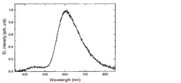
- 2 is an emission spectrum of an organic electroluminescence device using Compound 1 of Example 3.
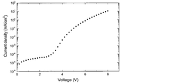
- 4 is a graph showing current density-voltage characteristics of an organic electroluminescence device using Compound 1 of Example 3.
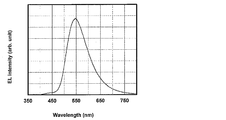
- 2 is an emission spectrum of an organic electroluminescence device using the compound 2 of Example 3.
- 6 is a graph showing current density-voltage characteristics of an organic electroluminescence device using Compound 2 of Example 3.
- 6 is a graph showing luminance-external quantum efficiency characteristics of an organic electroluminescence device using the compound 2 of Example 3.
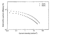
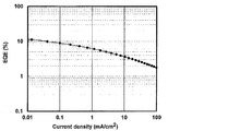
- 6 is a graph showing current density-external quantum efficiency characteristics of an organic electroluminescence device using Compound 2 of Example 3.
- 6 is a graph showing current density-external quantum efficiency characteristics of an organic electroluminescence device using the compound 6 of Example 3.
- 2 is an emission spectrum of an organic electroluminescence device using the compound 6 of Example 3.
- 6 is a graph showing current density-voltage characteristics of an organic electroluminescence device using the compound 6 of Example 3.
- 6 is a graph showing current density-external quantum efficiency characteristics of an organic electroluminescence device using the compound 6 of Example 3.
- a numerical range represented by using “to” means a range including numerical values described before and after “to” as a lower limit value and an upper limit value.
- the isotope species of the hydrogen atom present in the molecule of the compound used in the present invention is not particularly limited. For example, all the hydrogen atoms in the molecule may be 1 H, or a part or all of them are 2 H. (Deuterium D) may be used.
- D represents the bivalent group containing the structure represented by a following formula.
- the hydrogen atom present in the above structure may be substituted with a substituent.
- the number of substituents is not particularly limited, and the substituents may not be present. When two or more substituents are present, these substituents may be the same as or different from each other.
- substituents examples include a hydroxy group, a halogen atom, an alkyl group having 1 to 20 carbon atoms, an alkoxy group having 1 to 20 carbon atoms, an alkylthio group having 1 to 20 carbon atoms, an aryl group having 6 to 40 carbon atoms, and a carbon number.
- Examples thereof include 20 trialkylsilylalkyl groups, 5 to 20 trialkylsilylalkenyl groups, and 5 to 20 trialkylsilylalkynyl groups.
- those that can be substituted with a substituent may be further substituted.
- substituents are substituted or unsubstituted alkyl groups having 1 to 20 carbon atoms, alkoxy groups having 1 to 20 carbon atoms, substituted or unsubstituted aryl groups having 6 to 40 carbon atoms, and substituted groups having 3 to 40 carbon atoms. Or it is an unsubstituted heteroaryl group.
- Further preferred substituents are substituted or unsubstituted alkyl groups having 1 to 10 carbon atoms, substituted or unsubstituted alkoxy groups having 1 to 10 carbon atoms, substituted or unsubstituted aryl groups having 6 to 15 carbon atoms, 3 to 12 substituted or unsubstituted heteroaryl groups.
- the alkyl group may be linear, branched or cyclic, and more preferably has 1 to 6 carbon atoms. Specific examples include a methyl group, an ethyl group, a propyl group, a butyl group, and tert-butyl. Group, pentyl group, hexyl group and isopropyl group.
- the alkoxy group may be linear, branched or cyclic, and more preferably has 1 to 6 carbon atoms. Specific examples thereof include methoxy group, ethoxy group, propoxy group, butoxy group, tert-butoxy group. A group, a pentyloxy group, a hexyloxy group, and an isopropyloxy group.
- the aryl group that can be employed as the substituent may be a single ring or a condensed ring, and specific examples thereof include a phenyl group and a naphthyl group.
- the heteroaryl group may be a single ring or a condensed ring, and specific examples thereof include a pyridyl group, a pyridazyl group, a pyrimidyl group, a triazyl group, a triazolyl group, and a benzotriazolyl group.
- These heteroaryl groups may be a group bonded through a hetero atom or a group bonded through a carbon atom constituting a heteroaryl ring.
- D in the general formula (1) is preferably a group having a structure represented by the following general formula (2).
- R 1 to R 8 each independently represents a hydrogen atom or a substituent.
- R 1 to R 8 may all be hydrogen atoms.
- those substituents may be the same or different.
- R 1 and R 2 , R 2 and R 3 , R 3 and R 4 , R 5 and R 6 , R 6 and R 7 , and R 7 and R 8 may be bonded to each other to form a cyclic structure.
- the cyclic structure may be an aromatic ring or an alicyclic ring, may contain a hetero atom, and the cyclic structure may be a condensed ring of two or more rings.
- the hetero atom here is preferably selected from the group consisting of a nitrogen atom, an oxygen atom and a sulfur atom.
- Examples of cyclic structures formed include benzene ring, naphthalene ring, pyridine ring, pyridazine ring, pyrimidine ring, pyrazine ring, pyrrole ring, imidazole ring, pyrazole ring, triazole ring, imidazoline ring, oxazole ring, isoxazole ring, thiazole And a ring, an isothiazole ring, a cyclohexadiene ring, a cyclohexene ring, a cyclopentaene ring, a cycloheptatriene ring, a cycloheptadiene ring, and a cycloheptaene ring.
- Preferable examples of the structure represented by the general formula (2) include a structure in which R 1 to R 8 are all hydrogen atoms. Also, R 1 and R 8 , R 2 and R 7 , R 3 and R 6 , R 4 and R 5 are the same line symmetrical structure, R 1 and R 5 , R 2 and R 6 , R 3 And a rotationally symmetric structure in which R 7 and R 4 and R 8 are the same.
- A represents a group having a structure selected from the following group.
- Each hydrogen atom present in the structure described in the above group may be substituted with a substituent.
- the number of substituents is not particularly limited, and the substituents may not be present. When two or more substituents are present, these substituents may be the same as or different from each other.
- Examples of the substituent that can replace a hydrogen atom present in the structure described in the above group include a hydroxy group, a halogen atom, a cyano group, an alkyl group having 1 to 20 carbon atoms, and an alkoxy group having 1 to 20 carbon atoms.
- alkylthio group having 1 to 20 carbon atoms an alkyl-substituted amino group having 1 to 20 carbon atoms, an aryl-substituted amino group having 12 to 40 carbon atoms, an acyl group having 2 to 20 carbon atoms, an aryl group having 6 to 40 carbon atoms, Heteroaryl group having 3 to 40 carbon atoms, substituted or unsubstituted carbazolyl group having 12 to 40 carbon atoms, alkenyl group having 2 to 10 carbon atoms, alkynyl group having 2 to 10 carbon atoms, alkoxycarbonyl having 2 to 10 carbon atoms Groups, alkylsulfonyl groups having 1 to 10 carbon atoms, haloalkyl groups having 1 to 10 carbon atoms, amide groups, alkylamide groups having 2 to 10 carbon atoms, and trials having 3 to 20 carbon atoms Rushiriru group, trialkylsilyl group having 4-20 carbon atoms
- substituents are a halogen atom, a cyano group, a substituted or unsubstituted alkyl group having 1 to 20 carbon atoms, an alkoxy group having 1 to 20 carbon atoms, a substituted or unsubstituted aryl group having 6 to 40 carbon atoms, carbon A substituted or unsubstituted heteroaryl group having 3 to 40 carbon atoms, a substituted or unsubstituted dialkylamino group having 1 to 10 carbon atoms, a substituted or unsubstituted diarylamino group having 12 to 40 carbon atoms, and 12 to 40 carbon atoms A substituted or unsubstituted carbazolyl group; More preferred substituents are a fluorine atom, a chlorine atom, a cyano group, a substituted or unsubstituted alkyl group having 1 to 10 carbon atoms
- an unsubstituted dialkylamino group a substituted or unsubstituted diarylamino group having 12 to 40 carbon atoms, a substituted or unsubstituted aryl group having 6 to 15 carbon atoms, and a substituted or unsubstituted heteroaryl group having 3 to 12 carbon atoms It is a group.
- the hydrogen atoms bonded to adjacent ring skeleton atoms present in the structure described in the above group may be bonded to each other to form a cyclic structure.
- the cyclic structure may be an aromatic ring or an alicyclic ring, may contain a hetero atom, and the cyclic structure may be a condensed ring of two or more rings.
- the two A in the general formula (1) may be the same or different from each other, but are preferably the same.
- the whole molecule is preferably line symmetric or point symmetric.
- Ordinary luminescent materials have an AD structure in which A acting as an acceptor and D acting as a donor are combined.
- the compound represented by the general formula (1) has a structure of ADA, and two A acting as an acceptor are bonded to D acting as a donor.
- a and D when two or more A's are bonded, there is a general concern that the function as an acceptor cancels and there is a risk that the molecule does not function effectively as a luminescent material.
- a and D in accordance with the present invention, a light emitting material having high luminous efficiency and excellent effects can be provided. This is presumably because the HOMO and LUMO spreads were controlled at the molecular level to satisfy the preferable conditions for the light-emitting material.
- the compound represented by the general formula (1) is preferably a compound having a structure represented by the following general formula (3).
- R 1 to R 8 and R 11 to R 20 each independently represents a hydrogen atom or a substituent.
- R 1 and R 2 , R 2 and R 3 , R 3 and R 4 , R 5 and R 6 , R 6 and R 7 , R 7 and R 8 , R 11 and R 12 , R 12 and R 13 , R 13 And R 14 , R 14 and R 15 , R 16 and R 17 , R 17 and R 18 , R 18 and R 19 , and R 19 and R 20 may be bonded to each other to form a cyclic structure.
- the substituents that R 1 to R 8 can take the corresponding description of the general formula (1) can be referred to.
- R 12 is a cyano group or a group having the following structure (however, a hydrogen atom may be substituted with a substituent)
- R 13 is a cyano group or a group having any structure of the following group (wherein a hydrogen atom may be substituted with a substituent)
- R 17 is a cyano group or a group having the following structure (however, a hydrogen atom may be substituted with a substituent), R 18 is a cyano group or a group of any of the following groups (wherein a hydrogen atom may be substituted with a substituent), or R 17 and R 18 are bonded to each other, and together with the benzene ring to which R 17 and R 18 are bonded, a group that forms one of the following structures (however, a hydrogen atom may be substituted with a substituent) ).
- R 1 to R 8 in the general formula (3) are each independently a hydrogen atom, a substituted or unsubstituted alkyl group having 1 to 10 carbon atoms, a substituted or unsubstituted alkoxy group having 1 to 10 carbon atoms, a carbon number of 6
- a substituted or unsubstituted aryl group having 15 to 15 carbon atoms and a substituted or unsubstituted heteroaryl group having 3 to 12 carbon atoms are preferable.
- R 12 , R 13 , R 17 and R 18 in the general formula (3) have a substituent so as to satisfy the above conditions ⁇ 1> and ⁇ 2>.
- R 11 to R 18 are each independently a hydrogen atom, a fluorine atom, a chlorine atom, a cyano group, a substituted or unsubstituted alkyl group having 1 to 10 carbon atoms, a substituted or unsubstituted alkoxy group having 1 to 10 carbon atoms, carbon A substituted or unsubstituted dialkylamino group having 1 to 10 carbon atoms, a substituted or unsubstituted diarylamino group having 12 to 40 carbon atoms, a substituted or unsubstituted aryl group having 6 to 15 carbon atoms, or 3 to 12 carbon atoms It is preferably a substituted or unsubstituted heteroaryl group.
- the substituent in which the hydrogen atom having the structure described in the above ⁇ 1> and ⁇ 2> in the general formula (3) may be substituted is a fluorine atom, a chlorine atom, a cyano group, or a group having 1 to 10 carbon atoms.
- Substituted or unsubstituted alkyl group substituted or unsubstituted alkoxy group having 1 to 10 carbon atoms, substituted or unsubstituted dialkylamino group having 1 to 10 carbon atoms, substituted or unsubstituted diarylamino group having 12 to 40 carbon atoms It is preferably selected from the group consisting of a group, a substituted or unsubstituted aryl group having 6 to 15 carbon atoms, and a substituted or unsubstituted heteroaryl group having 3 to 12 carbon atoms.
- the molecular weight of the compound represented by the general formula (1) is, for example, 1500 or less when the organic layer containing the compound represented by the general formula (1) is intended to be formed by vapor deposition. Preferably, it is preferably 1200 or less, more preferably 1000 or less, and even more preferably 800 or less.
- the lower limit of the molecular weight is the molecular weight of the minimum compound represented by the general formula (1).
- the compound represented by the general formula (1) may be formed by a coating method regardless of the molecular weight. If a coating method is used, a film can be formed even with a compound having a relatively large molecular weight.
- a compound containing a plurality of structures represented by the general formula (1) in the molecule as a light emitting material.
- a polymer obtained by previously polymerizing a polymerizable group in the structure represented by the general formula (1) and polymerizing the polymerizable group as a light emitting material.
- a repeating unit is prepared by preparing a monomer containing a polymerizable functional group in either A or D of the general formula (1) and polymerizing the monomer alone or copolymerizing with another monomer. It is conceivable to obtain a polymer having the above and use the polymer as a light emitting material.
- dimers and trimers are obtained by reacting compounds having a structure represented by the general formula (1) and used as a luminescent material.
- Examples of the polymer having a repeating unit containing a structure represented by the general formula (1) include a polymer containing a structure represented by the following general formula (4) or (5).
- Q represents a group including the structure represented by the general formula (1)
- L 1 and L 2 represent a linking group.
- the linking group preferably has 0 to 20 carbon atoms, more preferably 1 to 15 carbon atoms, and still more preferably 2 to 10 carbon atoms. And preferably has a structure represented by - linking group -X 11 -L 11.
- X 11 represents an oxygen atom or a sulfur atom, and is preferably an oxygen atom.
- L 11 represents a linking group, preferably a substituted or unsubstituted alkylene group, or a substituted or unsubstituted arylene group, and a substituted or unsubstituted alkylene group having 1 to 10 carbon atoms, or a substituted or unsubstituted group A phenylene group is more preferable.
- R 101 , R 102 , R 103 and R 104 each independently represent a substituent.
- it is a substituted or unsubstituted alkyl group having 1 to 6 carbon atoms, a substituted or unsubstituted alkoxy group having 1 to 6 carbon atoms, or a halogen atom, more preferably an unsubstituted alkyl group having 1 to 3 carbon atoms.
- An unsubstituted alkoxy group having 1 to 3 carbon atoms, a fluorine atom, and a chlorine atom and more preferably an unsubstituted alkyl group having 1 to 3 carbon atoms and an unsubstituted alkoxy group having 1 to 3 carbon atoms.
- the linking group represented by L 1 and L 2 is any one of A or D in the structure of the general formula (1) constituting R and R 1 to R 8 and R 11 to R 18 in the structure of the general formula (3). Can be combined. Two or more linking groups may be linked to one Q to form a crosslinked structure or a network structure.
- repeating unit examples include structures represented by the following formulas (6) to (9).
- a hydroxy group is introduced into either A or D of the structure of the general formula (1), and the following compound is used as a linker: It can be synthesized by reacting to introduce a polymerizable group and polymerizing the polymerizable group.
- the polymer containing a structure represented by the general formula (1) in the molecule may be a polymer consisting only of a repeating unit having the structure represented by the general formula (1), or other structures may be used. It may be a polymer containing repeating units.
- the repeating unit having a structure represented by the general formula (1) contained in the polymer may be a single type or two or more types. Examples of the repeating unit not having the structure represented by the general formula (1) include those derived from monomers used in ordinary copolymerization. Examples thereof include a repeating unit derived from a monomer having an ethylenically unsaturated bond such as ethylene and styrene.
- the compound represented by the general formula (1) can be synthesized by combining known reactions. For example, it can be synthesized according to the following scheme. For the explanation of D and A in the above formula, the corresponding description in the general formula (1) can be referred to.
- X in the above formula represents a halogen atom, and examples thereof include a fluorine atom, a chlorine atom, a bromine atom and an iodine atom, and a chlorine atom, a bromine atom and an iodine atom are preferable.
- the compound represented by the general formula (3) can be synthesized by the following scheme. However, the scheme described below shows a synthesis method when R 11 and R 16 , R 12 and R 17 , R 13 and R 18 , R 14 and R 19 , and R 15 and R 20 are the same. is there.
- R 1 to R 8 and R 11 to R 20 in the above formula the corresponding description in the general formula (3) can be referred to.
- X in the above formula represents a halogen atom.
- the reactions in the above two schemes apply known reactions, and known reaction conditions can be appropriately selected and used. The details of the above reaction can be referred to the synthesis examples described below.
- the compound represented by the general formula (1) can also be synthesized by combining other known synthesis reactions.
- the compound represented by the general formula (1) of the present invention is useful as a light emitting material of an organic light emitting device. For this reason, the compound represented by General formula (1) of this invention can be effectively used as a luminescent material for the light emitting layer of an organic light emitting element.
- the compound represented by the general formula (1) includes a delayed fluorescent material (delayed phosphor) that emits delayed fluorescence. That is, the present invention relates to a delayed phosphor having a structure represented by the general formula (1), an invention using a compound represented by the general formula (1) as a delayed phosphor, and a general formula (1).
- An invention of a method for emitting delayed fluorescence using the represented compound is also provided.
- An organic light emitting device using such a compound as a light emitting material emits delayed fluorescence and has a feature of high luminous efficiency. The principle will be described below by taking an organic electroluminescence element as an example.
- the organic electroluminescence element carriers are injected into the light emitting material from both positive and negative electrodes to generate an excited light emitting material and emit light.
- 25% of the generated excitons are excited to the excited singlet state, and the remaining 75% are excited to the excited triplet state. Therefore, the use efficiency of energy is higher when phosphorescence, which is light emission from an excited triplet state, is used.
- the excited triplet state has a long lifetime, energy saturation occurs due to saturation of the excited state and interaction with excitons in the excited triplet state, and in general, the quantum yield of phosphorescence is often not high.
- delayed fluorescent materials after energy transition to an excited triplet state due to intersystem crossing, etc., are then crossed back to an excited singlet state due to triplet-triplet annihilation or absorption of thermal energy, and emit fluorescence.
- a thermally activated delayed fluorescent material by absorption of thermal energy is particularly useful.
- excitons in the excited singlet state emit fluorescence as usual.
- excitons in the excited triplet state absorb heat generated by the device and cross between the excited singlets to emit fluorescence.
- the light is emitted from the excited singlet, the light is emitted at the same wavelength as the fluorescence, but the light lifetime (luminescence lifetime) generated by the reverse intersystem crossing from the excited triplet state to the excited singlet state is normal. Since the fluorescence becomes longer than the fluorescence and phosphorescence, it is observed as fluorescence delayed from these. This can be defined as delayed fluorescence. If such a heat-activated exciton transfer mechanism is used, the ratio of the compound in an excited singlet state, which normally generated only 25%, is increased to 25% or more by absorbing thermal energy after carrier injection. It can be raised.
- the heat of the device will sufficiently cause intersystem crossing from the excited triplet state to the excited singlet state and emit delayed fluorescence. Efficiency can be improved dramatically.
- the compound represented by the general formula (1) of the present invention as a light-emitting material of a light-emitting layer, excellent organic light-emitting devices such as an organic photoluminescence device (organic PL device) and an organic electroluminescence device (organic EL device) Can be provided.
- the compound represented by the general formula (1) of the present invention may have a function of assisting light emission of another light emitting material included in the light emitting layer as a so-called assist dopant. That is, the compound represented by the general formula (1) of the present invention contained in the light emitting layer includes the lowest excitation singlet energy level of the host material contained in the light emitting layer and the lowest excitation of other light emitting materials contained in the light emitting layer.
- the organic photoluminescence element has a structure in which at least a light emitting layer is formed on a substrate.
- the organic electroluminescence element has a structure in which an organic layer is formed at least between an anode, a cathode, and an anode and a cathode.
- the organic layer includes at least a light emitting layer, and may consist of only the light emitting layer, or may have one or more organic layers in addition to the light emitting layer. Examples of such other organic layers include a hole transport layer, a hole injection layer, an electron blocking layer, a hole blocking layer, an electron injection layer, an electron transport layer, and an exciton blocking layer.
- the hole transport layer may be a hole injection / transport layer having a hole injection function
- the electron transport layer may be an electron injection / transport layer having an electron injection function.
- FIG. 1 A specific example of the structure of an organic electroluminescence element is shown in FIG.
- 1 is a substrate
- 2 is an anode
- 3 is a hole injection layer
- 4 is a hole transport layer
- 5 is a light emitting layer
- 6 is an electron transport layer
- 7 is a cathode.
- each member and each layer of an organic electroluminescent element are demonstrated.
- substrate and a light emitting layer corresponds also to the board
- the organic electroluminescence device of the present invention is preferably supported on a substrate.
- the substrate is not particularly limited and may be any substrate conventionally used for organic electroluminescence elements.
- a substrate made of glass, transparent plastic, quartz, silicon, or the like can be used.
- an electrode material made of a metal, an alloy, an electrically conductive compound, or a mixture thereof having a high work function (4 eV or more) is preferably used.
- electrode materials include metals such as Au, and conductive transparent materials such as CuI, indium tin oxide (ITO), SnO 2 , and ZnO.
- conductive transparent materials such as CuI, indium tin oxide (ITO), SnO 2 , and ZnO.
- an amorphous material such as IDIXO (In 2 O 3 —ZnO) that can form a transparent conductive film may be used.
- a thin film may be formed by vapor deposition or sputtering of these electrode materials, and a pattern of a desired shape may be formed by photolithography, or when pattern accuracy is not so high (about 100 ⁇ m or more) ), A pattern may be formed through a mask having a desired shape at the time of vapor deposition or sputtering of the electrode material.
- wet film-forming methods such as a printing system and a coating system, can also be used.
- the transmittance be greater than 10%, and the sheet resistance as the anode is preferably several hundred ⁇ / ⁇ or less.
- the film thickness depends on the material, it is usually selected in the range of 10 to 1000 nm, preferably 10 to 200 nm.
- cathode a material having a low work function (4 eV or less) metal (referred to as an electron injecting metal), an alloy, an electrically conductive compound, and a mixture thereof as an electrode material is used.
- electrode materials include sodium, sodium-potassium alloy, magnesium, lithium, magnesium / copper mixture, magnesium / silver mixture, magnesium / aluminum mixture, magnesium / indium mixture, aluminum / aluminum oxide (Al 2 O 3 ) Mixtures, indium, lithium / aluminum mixtures, rare earth metals and the like.
- a mixture of an electron injecting metal and a second metal which is a stable metal having a larger work function value than this for example, a magnesium / silver mixture
- Suitable are a magnesium / aluminum mixture, a magnesium / indium mixture, an aluminum / aluminum oxide (Al 2 O 3 ) mixture, a lithium / aluminum mixture, aluminum and the like.
- the cathode can be produced by forming a thin film of these electrode materials by a method such as vapor deposition or sputtering.
- the sheet resistance as the cathode is preferably several hundred ⁇ / ⁇ or less, and the film thickness is usually selected in the range of 10 nm to 5 ⁇ m, preferably 50 to 200 nm.
- the emission luminance is advantageously improved.
- a transparent or semi-transparent cathode can be produced. By applying this, an element in which both the anode and the cathode are transparent is used. Can be produced.
- the light emitting layer is a layer that emits light after excitons are generated by recombination of holes and electrons injected from each of the anode and the cathode, and the light emitting material may be used alone for the light emitting layer. , Preferably including a luminescent material and a host material.
- a luminescent material the 1 type (s) or 2 or more types chosen from the compound group of this invention represented by General formula (1) can be used.
- a host material in addition to the light emitting material in the light emitting layer.
- the host material an organic compound having at least one of excited singlet energy and excited triplet energy higher than that of the light emitting material of the present invention can be used.
- singlet excitons and triplet excitons generated in the light emitting material of the present invention can be confined in the molecules of the light emitting material of the present invention, and the light emission efficiency can be sufficiently extracted.
- high luminous efficiency can be obtained, so that host materials that can achieve high luminous efficiency are particularly limited. And can be used in the present invention.
- the organic light emitting device or organic electroluminescent device of the present invention light emission is generated from the light emitting material of the present invention contained in the light emitting layer.
- This emission includes both fluorescence and delayed fluorescence.
- part of the light emission may include light emission from the host material.
- the amount of the compound of the present invention, which is a light emitting material is preferably 0.1% by weight or more, more preferably 1% by weight or more, and 50% or more. It is preferably no greater than wt%, more preferably no greater than 20 wt%, and even more preferably no greater than 10 wt%.
- the host material in the light-emitting layer is preferably an organic compound that has a hole transporting ability and an electron transporting ability, prevents the emission of longer wavelengths, and has a high glass transition temperature.
- the injection layer is a layer provided between the electrode and the organic layer for lowering the driving voltage and improving the luminance of light emission.
- the injection layer can be provided as necessary.
- the blocking layer is a layer that can prevent diffusion of charges (electrons or holes) and / or excitons existing in the light emitting layer to the outside of the light emitting layer.
- the electron blocking layer can be disposed between the light emitting layer and the hole transport layer and blocks electrons from passing through the light emitting layer toward the hole transport layer.
- a hole blocking layer can be disposed between the light emitting layer and the electron transporting layer to prevent holes from passing through the light emitting layer toward the electron transporting layer.
- the blocking layer can also be used to block excitons from diffusing outside the light emitting layer. That is, each of the electron blocking layer and the hole blocking layer can also function as an exciton blocking layer.
- the term “electron blocking layer” or “exciton blocking layer” as used herein is used in the sense of including a layer having the functions of an electron blocking layer and an exciton blocking layer in one layer.
- the hole blocking layer has a function of an electron transport layer in a broad sense.
- the hole blocking layer has a role of blocking holes from reaching the electron transport layer while transporting electrons, thereby improving the recombination probability of electrons and holes in the light emitting layer.
- the material for the hole blocking layer the material for the electron transport layer described later can be used as necessary.
- the electron blocking layer has a function of transporting holes in a broad sense.
- the electron blocking layer has a role to block electrons from reaching the hole transport layer while transporting holes, thereby improving the probability of recombination of electrons and holes in the light emitting layer. .
- the exciton blocking layer is a layer for preventing excitons generated by recombination of holes and electrons in the light emitting layer from diffusing into the charge transport layer. It becomes possible to efficiently confine in the light emitting layer, and the light emission efficiency of the device can be improved.
- the exciton blocking layer can be inserted on either the anode side or the cathode side adjacent to the light emitting layer, or both can be inserted simultaneously.
- the layer when the exciton blocking layer is provided on the anode side, the layer can be inserted adjacent to the light emitting layer between the hole transport layer and the light emitting layer, and when inserted on the cathode side, the light emitting layer and the cathode Between the luminescent layer and the light-emitting layer.
- a hole injection layer, an electron blocking layer, or the like can be provided between the anode and the exciton blocking layer adjacent to the anode side of the light emitting layer, and the excitation adjacent to the cathode and the cathode side of the light emitting layer can be provided.
- an electron injection layer, an electron transport layer, a hole blocking layer, and the like can be provided.
- the blocking layer is disposed, at least one of the excited singlet energy and the excited triplet energy of the material used as the blocking layer is preferably higher than the excited singlet energy and the excited triplet energy of the light emitting material.
- the hole transport layer is made of a hole transport material having a function of transporting holes, and the hole transport layer can be provided as a single layer or a plurality of layers.
- the hole transport material has any one of hole injection or transport and electron barrier properties, and may be either organic or inorganic.
- hole transport materials that can be used include, for example, triazole derivatives, oxadiazole derivatives, imidazole derivatives, carbazole derivatives, indolocarbazole derivatives, polyarylalkane derivatives, pyrazoline derivatives and pyrazolone derivatives, phenylenediamine derivatives, arylamine derivatives, Examples include amino-substituted chalcone derivatives, oxazole derivatives, styrylanthracene derivatives, fluorenone derivatives, hydrazone derivatives, stilbene derivatives, silazane derivatives, aniline copolymers, and conductive polymer oligomers, particularly thiophene oligomers.
- An aromatic tertiary amine compound and an styrylamine compound are preferably used, and an aromatic tertiary amine compound is more preferably used.
- the electron transport layer is made of a material having a function of transporting electrons, and the electron transport layer can be provided as a single layer or a plurality of layers.
- the electron transport material (which may also serve as a hole blocking material) may have a function of transmitting electrons injected from the cathode to the light emitting layer.
- Examples of the electron transport layer that can be used include nitro-substituted fluorene derivatives, diphenylquinone derivatives, thiopyran dioxide oxide derivatives, carbodiimides, fluorenylidenemethane derivatives, anthraquinodimethane and anthrone derivatives, oxadiazole derivatives, and the like.
- a thiadiazole derivative in which the oxygen atom of the oxadiazole ring is substituted with a sulfur atom, and a quinoxaline derivative having a quinoxaline ring known as an electron withdrawing group can also be used as an electron transport material.
- a polymer material in which these materials are introduced into a polymer chain or these materials are used as a polymer main chain can also be used.
- the compound represented by the general formula (1) may be used not only for the light emitting layer but also for layers other than the light emitting layer.
- the compound represented by General formula (1) used for a light emitting layer and the compound represented by General formula (1) used for layers other than a light emitting layer may be same or different.
- the compound represented by the general formula (1) may be used for the injection layer, blocking layer, hole blocking layer, electron blocking layer, exciton blocking layer, hole transporting layer, electron transporting layer, and the like. .
- the method for forming these layers is not particularly limited, and the layer may be formed by either a dry process or a wet process.
- the preferable material which can be used for an organic electroluminescent element is illustrated concretely.
- the material that can be used in the present invention is not limited to the following exemplary compounds. Moreover, even if it is a compound illustrated as a material which has a specific function, it can also be diverted as a material which has another function.
- R and R 2 to R 7 each independently represent a hydrogen atom or a substituent.
- n represents an integer of 3 to 5.
- the organic electroluminescence device produced by the above-described method emits light by applying an electric field between the anode and the cathode of the obtained device. At this time, if the light is emitted by excited singlet energy, light having a wavelength corresponding to the energy level is confirmed as fluorescence emission and delayed fluorescence emission. In addition, in the case of light emission by excited triplet energy, a wavelength corresponding to the energy level is confirmed as phosphorescence. Since normal fluorescence has a shorter fluorescence lifetime than delayed fluorescence, the emission lifetime can be distinguished from fluorescence and delayed fluorescence.
- the excited triplet energy is unstable and is converted into heat and the like, and the lifetime is short and it is immediately deactivated.
- the excited triplet energy of a normal organic compound it can be measured by observing light emission under extremely low temperature conditions.
- the organic electroluminescence element of the present invention can be applied to any of a single element, an element having a structure arranged in an array, and a structure in which an anode and a cathode are arranged in an XY matrix.
- an organic light emitting device with greatly improved light emission efficiency can be obtained by containing the compound represented by the general formula (1) in the light emitting layer.
- the organic light emitting device such as the organic electroluminescence device of the present invention can be further applied to various uses. For example, it is possible to produce an organic electroluminescence display device using the organic electroluminescence element of the present invention. For details, see “Organic EL Display” (Ohm Co., Ltd.) ) Can be referred to.
- the organic electroluminescence device of the present invention can be applied to organic electroluminescence illumination and backlights that are in great demand.
- the maximum point having a peak intensity of 10% or less of the maximum peak intensity of the spectrum is not included in the above-mentioned maximum value on the shortest wavelength side, and has the maximum slope value closest to the maximum value on the shortest wavelength side.
- the tangent drawn at the point where the value was taken was taken as the tangent to the rising edge of the phosphorescence spectrum on the short wavelength side.
- Example 1 Preparation and evaluation of organic photoluminescence device (solution)
- a toluene solution concentration 10 ⁇ 5 mol / L
- Compound 1 synthesized in Synthesis Example 1 was prepared and irradiated with ultraviolet light at 300 K while bubbling nitrogen, fluorescence at 586 nm was observed.
- the photoluminescence quantum efficiency in the toluene solution before and after the nitrogen bubble was measured at 300 K with an absolute PL quantum yield measurement device (Quantaurus-QY manufactured by Hamamatsu Photonics Co., Ltd.), it was 3.4% before the nitrogen bubble. Yes, 5.5% after nitrogen bubble.
- the photoluminescence quantum efficiency was 1.9% before the nitrogen bubble and 2.3% after the nitrogen bubble.
- the photoluminescence quantum efficiency was 4.7% before the nitrogen bubble and 9.7% after the nitrogen bubble.
- Example 2 Preparation and evaluation of organic photoluminescence device (thin film)
- FIG. 2 shows transient attenuation curves at temperatures of 50K, 100K, 150K, 200K, 250K, and 300K. It was confirmed that Compound 1 is a thermally activated delayed fluorescent material.
- ⁇ p at 300 K was 6.24 ns
- ⁇ d was 0.14 ⁇ s.
- FIG. 3 shows transient attenuation curves at respective temperatures of 50K, 100K, 150K, 200K, 250K, and 300K.
- Compound 2 was confirmed to be a thermally activated delayed fluorescent material.
- ⁇ p at 300 K was 6.83 ns
- ⁇ d was 6.69 ⁇ s.
- the photoluminescence quantum efficiency obtained using the same measuring apparatus as in Example 1 was 35.2% at 300 K (normal fluorescence 16.8%, delayed fluorescence 18.4%).
- ⁇ E ST was 0.10 eV.
- An organic photoluminescence device was prepared using Compound 5 instead of Compound 1, and the measurement was performed in the same manner.
- FIG. 3 shows transient attenuation curves at respective temperatures of 50K, 100K, 150K, 200K, 250K, and 300K.
- Compound 2 was confirmed to be a thermally activated delayed fluorescent material.
- ⁇ p at 300 K was 6.83 ns
- ⁇ d was 6.69 ⁇ s.
- FIG. 4 shows transient attenuation curves at respective temperatures of 50K, 100K, 150K, 200K, 250K, and 300K.
- Compound 5 was confirmed to be a thermally activated delayed fluorescent material.
- ⁇ p at 300 K was 12.18 ns and ⁇ d was 1.10 ⁇ s.
- the photoluminescence quantum efficiency obtained using the same measuring apparatus as Example 1 was 33.0% at 300K (normal fluorescence 20.6%, delayed fluorescence 12.4%).
- ⁇ E ST was 0.03 eV.
- An organic photoluminescence device was prepared using Compound 6 instead of Compound 1, and the measurement was performed in the same manner.
- FIG. 5 shows transient attenuation curves at respective temperatures of 50K, 100K, 150K, 200K, 250K, and 300K.
- Compound 6 was confirmed to be a thermally activated delayed fluorescent material.
- ⁇ p at 300 K was 4.12 ns, and ⁇ d was 53.00 ⁇ s.
- the photoluminescence quantum efficiency obtained using the same measuring apparatus as in Example 1 was 67.6% at 300 K (normal fluorescence 34.0%, delayed fluorescence 33.6%).
- ⁇ E ST was 0.19 eV.
- Example 3 Production and Evaluation of Organic Electroluminescence Element
- ITO indium tin oxide
- Lamination was performed at 0 ⁇ 10 ⁇ 4 Pa.
- ⁇ -NPD was formed on ITO to a thickness of 35 nm.
- Compound 1 and CBP were co-deposited from different vapor deposition sources to form a layer having a thickness of 15 nm as a light emitting layer. At this time, the concentration of Compound 1 was 2.0% by weight.
- TPBi is formed to a thickness of 65 nm
- further lithium fluoride (LiF) is vacuum-deposited to a thickness of 0.5 nm
- aluminum (Al) is evaporated to a thickness of 100 nm to form a cathode.
- a luminescence element was obtained.
- a semiconductor parameter analyzer manufactured by Agilent Technologies: E5273A
- an optical power meter measuring device manufactured by Newport: 1930C
- an optical spectrometer manufactured by Ocean Optics: USB2000
- the compound 2 is used in place of the compound 1, and the organic electroluminescence device having the concentration of the compound 2 in the light emitting layer of 2.0% by weight and the organic electroluminescent element having the concentration of the compound 2 in the light emitting layer of 6.0% by weight.
- a luminescence element was produced.
- the emission spectrum is shown in FIG. 8, the current density-voltage characteristic is shown in FIG. 9, the luminance-external quantum efficiency characteristic is shown in FIG. 10, and the current density-external quantum efficiency characteristic is shown in FIG.
- the organic electroluminescence device using Compound 2 as the light emitting material achieved a high external quantum efficiency of 8.8%.
- FIG. 13 shows the emission spectrum
- FIG. 14 shows the current density-voltage characteristics
- FIG. 15 shows the current density-external quantum efficiency characteristics.
- the organic electroluminescence device using Compound 6 as the light emitting material achieved a high external quantum efficiency of 11.3%.
- FIG. 12 shows the current density-external quantum efficiency characteristics when an organic electroluminescent device having a concentration of compound 6 in the light emitting layer of 6.0% by weight was produced. This organic electroluminescence device achieved a high external quantum efficiency of 12.1%.
- the compound of the present invention is useful as a luminescent material. For this reason, the compound of this invention is effectively used as a luminescent material for organic light emitting elements, such as an organic electroluminescent element. Since the compounds of the present invention include those that emit delayed fluorescence, it is also possible to provide an organic light emitting device with high luminous efficiency. For this reason, this invention has high industrial applicability.
Landscapes
- Chemical & Material Sciences (AREA)
- Organic Chemistry (AREA)
- Engineering & Computer Science (AREA)
- Materials Engineering (AREA)
- Manufacturing & Machinery (AREA)
- Electroluminescent Light Sources (AREA)
- Plural Heterocyclic Compounds (AREA)
Abstract
L'invention concerne un composé représenté par A-D-A utilisé en tant que matériau électroluminescent.
Priority Applications (1)
| Application Number | Priority Date | Filing Date | Title |
|---|---|---|---|
| JP2015518295A JP6277182B2 (ja) | 2013-05-24 | 2014-05-23 | 化合物、発光材料および有機発光素子 |
Applications Claiming Priority (2)
| Application Number | Priority Date | Filing Date | Title |
|---|---|---|---|
| JP2013-110382 | 2013-05-24 | ||
| JP2013110382 | 2013-05-24 |
Publications (1)
| Publication Number | Publication Date |
|---|---|
| WO2014189122A1 true WO2014189122A1 (fr) | 2014-11-27 |
Family
ID=51933673
Family Applications (1)
| Application Number | Title | Priority Date | Filing Date |
|---|---|---|---|
| PCT/JP2014/063638 WO2014189122A1 (fr) | 2013-05-24 | 2014-05-23 | Composé, matériau électroluminescent et élément électroluminescent organique |
Country Status (3)
| Country | Link |
|---|---|
| JP (1) | JP6277182B2 (fr) |
| TW (1) | TW201509920A (fr) |
| WO (1) | WO2014189122A1 (fr) |
Cited By (24)
| Publication number | Priority date | Publication date | Assignee | Title |
|---|---|---|---|---|
| WO2016111196A1 (fr) * | 2015-01-08 | 2016-07-14 | 国立大学法人九州大学 | Composé, mélange, couche photo-émettrice, élément électroluminescent organique, et dopant auxiliaire |
| JP2016130231A (ja) * | 2015-01-08 | 2016-07-21 | 国立大学法人九州大学 | 化合物、混合物、発光層、有機発光素子およびアシストドーパント |
| WO2019218347A1 (fr) * | 2018-05-18 | 2019-11-21 | Soochow University | Oligomère de n, n'-di(hétéro)aryl-5,10-dihydrophénazine, matériau actif de cathode, cathode, batterie associée et son procédé de préparation |
| WO2020076796A1 (fr) | 2018-10-09 | 2020-04-16 | Kyulux, Inc. | Nouvelle composition de matière destinée à être utilisée dans des diodes électroluminescentes organiques |
| WO2021157642A1 (fr) | 2020-02-04 | 2021-08-12 | 株式会社Kyulux | Matériau hôte, composition, et élément luminescent organique |
| US11101440B2 (en) | 2015-07-01 | 2021-08-24 | Kyushu University, National University Corporation | Organic electroluminescent device |
| WO2021235549A1 (fr) | 2020-05-22 | 2021-11-25 | 株式会社Kyulux | Composé, matériau électroluminescent et élément électroluminescent |
| WO2022025248A1 (fr) | 2020-07-31 | 2022-02-03 | 株式会社Kyulux | Composé, matériau luminescent, et élément luminescent |
| US11335872B2 (en) | 2016-09-06 | 2022-05-17 | Kyulux, Inc. | Organic light-emitting device |
| WO2022168956A1 (fr) | 2021-02-04 | 2022-08-11 | 株式会社Kyulux | Composé, matériau électroluminescent et élément électroluminescent organique |
| US11476435B2 (en) | 2017-08-24 | 2022-10-18 | Kyushu University, National University Corporation | Film and organic light-emitting device containing perovskite-type compound and organic light-emitting material |
| US11482679B2 (en) | 2017-05-23 | 2022-10-25 | Kyushu University, National University Corporation | Compound, light-emitting lifetime lengthening agent, use of n-type compound, film and light-emitting device |
| WO2022244503A1 (fr) | 2021-05-20 | 2022-11-24 | 株式会社Kyulux | Elément électroluminescent organique |
| WO2022270602A1 (fr) | 2021-06-23 | 2022-12-29 | 株式会社Kyulux | Élément électroluminescent organique et film |
| WO2022270354A1 (fr) | 2021-06-23 | 2022-12-29 | 株式会社Kyulux | Composé, matériau électroluminescent et élément électroluminescent organique |
| WO2023282224A1 (fr) | 2021-07-06 | 2023-01-12 | 株式会社Kyulux | Élément émetteur de lumière organique et son procédé de conception |
| JP2023036820A (ja) * | 2012-08-03 | 2023-03-14 | 株式会社半導体エネルギー研究所 | 発光素子、発光装置、照明装置および電子機器 |
| WO2023053835A1 (fr) | 2021-09-28 | 2023-04-06 | 株式会社Kyulux | Composé, composition, matériau hôte, matériau barrière aux électrons et élément électroluminescent organique |
| WO2023090288A1 (fr) | 2021-11-19 | 2023-05-25 | 株式会社Kyulux | Composé, matériau électroluminescent et élément électroluminescent |
| US11692065B2 (en) | 2019-03-29 | 2023-07-04 | Cornell University | Phenazine copolymers and uses thereof |
| WO2023140130A1 (fr) | 2022-01-19 | 2023-07-27 | 株式会社Kyulux | Composé, matériau électroluminescent et dispositif électroluminescent organique |
| US11795185B2 (en) | 2017-12-13 | 2023-10-24 | Lg Display Co., Ltd. | Compound for electron-transport material and organic light emitting diode including the same |
| US11930654B2 (en) | 2017-07-06 | 2024-03-12 | Kyulux, Inc. | Organic light-emitting element |
| US12048175B2 (en) | 2015-12-28 | 2024-07-23 | Kyushu University, National University Corporation | Organic electroluminescent device |
Families Citing this family (2)
| Publication number | Priority date | Publication date | Assignee | Title |
|---|---|---|---|---|
| US11355713B2 (en) | 2019-06-24 | 2022-06-07 | Wuhan China Star Optoelectronics Semiconductor Display Technology Co., Ltd. | Hole transport material, manufacturing method thereof, and electroluminescent device thereof |
| CN110299460B (zh) * | 2019-06-24 | 2020-11-24 | 武汉华星光电半导体显示技术有限公司 | 一种空穴传输材料、制备方法及电致发光器件 |
Citations (3)
| Publication number | Priority date | Publication date | Assignee | Title |
|---|---|---|---|---|
| WO2012067415A2 (fr) * | 2010-11-19 | 2012-05-24 | 덕산하이메탈(주) | Composé et dispositif électronique organique l'utilisant, et terminal comprenant le dispositif électronique organique |
| WO2013172255A1 (fr) * | 2012-05-17 | 2013-11-21 | 国立大学法人九州大学 | Composé, matériau émetteur de lumière et élément organique émetteur de lumière |
| WO2014034535A1 (fr) * | 2012-08-30 | 2014-03-06 | 国立大学法人九州大学 | Matière émettant de la lumière, composé et élément émettant de la lumière organique utilisant la matière émettant de la lumière |
-
2014
- 2014-05-23 WO PCT/JP2014/063638 patent/WO2014189122A1/fr active Application Filing
- 2014-05-23 JP JP2015518295A patent/JP6277182B2/ja active Active
- 2014-05-23 TW TW103118144A patent/TW201509920A/zh unknown
Patent Citations (3)
| Publication number | Priority date | Publication date | Assignee | Title |
|---|---|---|---|---|
| WO2012067415A2 (fr) * | 2010-11-19 | 2012-05-24 | 덕산하이메탈(주) | Composé et dispositif électronique organique l'utilisant, et terminal comprenant le dispositif électronique organique |
| WO2013172255A1 (fr) * | 2012-05-17 | 2013-11-21 | 国立大学法人九州大学 | Composé, matériau émetteur de lumière et élément organique émetteur de lumière |
| WO2014034535A1 (fr) * | 2012-08-30 | 2014-03-06 | 国立大学法人九州大学 | Matière émettant de la lumière, composé et élément émettant de la lumière organique utilisant la matière émettant de la lumière |
Cited By (28)
| Publication number | Priority date | Publication date | Assignee | Title |
|---|---|---|---|---|
| JP2023036820A (ja) * | 2012-08-03 | 2023-03-14 | 株式会社半導体エネルギー研究所 | 発光素子、発光装置、照明装置および電子機器 |
| JP2023071999A (ja) * | 2012-08-03 | 2023-05-23 | 株式会社半導体エネルギー研究所 | 発光素子 |
| JP7520099B2 (ja) | 2012-08-03 | 2024-07-22 | 株式会社半導体エネルギー研究所 | 発光素子、発光装置、照明装置および電子機器 |
| JP2016130231A (ja) * | 2015-01-08 | 2016-07-21 | 国立大学法人九州大学 | 化合物、混合物、発光層、有機発光素子およびアシストドーパント |
| WO2016111196A1 (fr) * | 2015-01-08 | 2016-07-14 | 国立大学法人九州大学 | Composé, mélange, couche photo-émettrice, élément électroluminescent organique, et dopant auxiliaire |
| US11101440B2 (en) | 2015-07-01 | 2021-08-24 | Kyushu University, National University Corporation | Organic electroluminescent device |
| US12048175B2 (en) | 2015-12-28 | 2024-07-23 | Kyushu University, National University Corporation | Organic electroluminescent device |
| US11335872B2 (en) | 2016-09-06 | 2022-05-17 | Kyulux, Inc. | Organic light-emitting device |
| US11482679B2 (en) | 2017-05-23 | 2022-10-25 | Kyushu University, National University Corporation | Compound, light-emitting lifetime lengthening agent, use of n-type compound, film and light-emitting device |
| US11930654B2 (en) | 2017-07-06 | 2024-03-12 | Kyulux, Inc. | Organic light-emitting element |
| US11476435B2 (en) | 2017-08-24 | 2022-10-18 | Kyushu University, National University Corporation | Film and organic light-emitting device containing perovskite-type compound and organic light-emitting material |
| US11795185B2 (en) | 2017-12-13 | 2023-10-24 | Lg Display Co., Ltd. | Compound for electron-transport material and organic light emitting diode including the same |
| US11909047B2 (en) | 2018-05-18 | 2024-02-20 | Soochow University | Oligomer of N,N′-di(hetero)aryl-5,10-dihydrophenazine, cathode active material, cathode, battery thereof, and process for preparing same |
| WO2019218347A1 (fr) * | 2018-05-18 | 2019-11-21 | Soochow University | Oligomère de n, n'-di(hétéro)aryl-5,10-dihydrophénazine, matériau actif de cathode, cathode, batterie associée et son procédé de préparation |
| WO2020076796A1 (fr) | 2018-10-09 | 2020-04-16 | Kyulux, Inc. | Nouvelle composition de matière destinée à être utilisée dans des diodes électroluminescentes organiques |
| US11692065B2 (en) | 2019-03-29 | 2023-07-04 | Cornell University | Phenazine copolymers and uses thereof |
| WO2021157593A1 (fr) | 2020-02-04 | 2021-08-12 | 株式会社Kyulux | Composition, film, élément électroluminescent organique, procédé de fourniture de composition électroluminescente, et programme |
| WO2021157642A1 (fr) | 2020-02-04 | 2021-08-12 | 株式会社Kyulux | Matériau hôte, composition, et élément luminescent organique |
| WO2021235549A1 (fr) | 2020-05-22 | 2021-11-25 | 株式会社Kyulux | Composé, matériau électroluminescent et élément électroluminescent |
| WO2022025248A1 (fr) | 2020-07-31 | 2022-02-03 | 株式会社Kyulux | Composé, matériau luminescent, et élément luminescent |
| WO2022168956A1 (fr) | 2021-02-04 | 2022-08-11 | 株式会社Kyulux | Composé, matériau électroluminescent et élément électroluminescent organique |
| WO2022244503A1 (fr) | 2021-05-20 | 2022-11-24 | 株式会社Kyulux | Elément électroluminescent organique |
| WO2022270354A1 (fr) | 2021-06-23 | 2022-12-29 | 株式会社Kyulux | Composé, matériau électroluminescent et élément électroluminescent organique |
| WO2022270602A1 (fr) | 2021-06-23 | 2022-12-29 | 株式会社Kyulux | Élément électroluminescent organique et film |
| WO2023282224A1 (fr) | 2021-07-06 | 2023-01-12 | 株式会社Kyulux | Élément émetteur de lumière organique et son procédé de conception |
| WO2023053835A1 (fr) | 2021-09-28 | 2023-04-06 | 株式会社Kyulux | Composé, composition, matériau hôte, matériau barrière aux électrons et élément électroluminescent organique |
| WO2023090288A1 (fr) | 2021-11-19 | 2023-05-25 | 株式会社Kyulux | Composé, matériau électroluminescent et élément électroluminescent |
| WO2023140130A1 (fr) | 2022-01-19 | 2023-07-27 | 株式会社Kyulux | Composé, matériau électroluminescent et dispositif électroluminescent organique |
Also Published As
| Publication number | Publication date |
|---|---|
| TW201509920A (zh) | 2015-03-16 |
| JPWO2014189122A1 (ja) | 2017-02-23 |
| JP6277182B2 (ja) | 2018-02-07 |
Similar Documents
| Publication | Publication Date | Title |
|---|---|---|
| JP6277182B2 (ja) | 化合物、発光材料および有機発光素子 | |
| JP5594750B2 (ja) | 化合物、発光材料および有機発光素子 | |
| JP6318155B2 (ja) | 化合物、発光材料および有機発光素子 | |
| JP6225111B2 (ja) | 発光材料、化合物、およびそれらを用いた有機発光素子 | |
| JP6326050B2 (ja) | 化合物、発光材料および有機発光素子 | |
| JP6472383B2 (ja) | 発光材料、並びに、これを用いた遅延蛍光体および有機発光素子 | |
| JP6263524B2 (ja) | 化合物、発光材料および有機発光素子 | |
| JP6293417B2 (ja) | 化合物、発光材料および有機発光素子 | |
| JP6367189B2 (ja) | 発光材料、有機発光素子および化合物 | |
| JP5679496B2 (ja) | 有機発光素子ならびにそれに用いる遅延蛍光材料および化合物 | |
| WO2015080183A1 (fr) | Substance électroluminescente, élément électroluminescent organique, et composé | |
| WO2015133501A1 (fr) | Matériau électroluminescent, élément organique électroluminescent et composé | |
| WO2013154064A1 (fr) | Élément électroluminescent organique, matériau électroluminescent et composé l'utilisant | |
| WO2013161437A1 (fr) | Matériau électroluminescent et élément électroluminescent organique | |
| WO2015137244A1 (fr) | Matériau d'émission de lumière, élément électroluminescent organique et composé associé | |
| JPWO2015129714A1 (ja) | 発光材料、有機発光素子および化合物 | |
| JP2014043541A (ja) | 有機発光素子ならびにそれに用いる発光材料および化合物 | |
| JP6647514B2 (ja) | 有機発光素子ならびにそれに用いる発光材料および化合物 | |
| JP2014009352A (ja) | 発光材料、化合物および有機発光素子 | |
| JP6249150B2 (ja) | 発光材料およびそれを用いた有機発光素子 | |
| WO2014126076A1 (fr) | Composé, matière électroluminescente et élément électroluminescent organique | |
| JP2018111751A (ja) | 発光材料、化合物および有機発光素子 | |
| JP2016084283A (ja) | 化合物、発光材料および有機発光素子 | |
| JP2016084284A (ja) | 化合物、発光材料および有機発光素子 |
Legal Events
| Date | Code | Title | Description |
|---|---|---|---|
| 121 | Ep: the epo has been informed by wipo that ep was designated in this application |
Ref document number: 14800491 Country of ref document: EP Kind code of ref document: A1 |
|
| ENP | Entry into the national phase |
Ref document number: 2015518295 Country of ref document: JP Kind code of ref document: A |
|
| NENP | Non-entry into the national phase |
Ref country code: DE |
|
| 122 | Ep: pct application non-entry in european phase |
Ref document number: 14800491 Country of ref document: EP Kind code of ref document: A1 |