WO2014185391A1 - Laminated header, heat exchanger, and air conditioner - Google Patents
Laminated header, heat exchanger, and air conditioner Download PDFInfo
- Publication number
- WO2014185391A1 WO2014185391A1 PCT/JP2014/062653 JP2014062653W WO2014185391A1 WO 2014185391 A1 WO2014185391 A1 WO 2014185391A1 JP 2014062653 W JP2014062653 W JP 2014062653W WO 2014185391 A1 WO2014185391 A1 WO 2014185391A1
- Authority
- WO
- WIPO (PCT)
- Prior art keywords
- plate
- heat exchanger
- flow path
- refrigerant
- header
- Prior art date
Links
Images


Classifications
-
- F—MECHANICAL ENGINEERING; LIGHTING; HEATING; WEAPONS; BLASTING
- F28—HEAT EXCHANGE IN GENERAL
- F28F—DETAILS OF HEAT-EXCHANGE AND HEAT-TRANSFER APPARATUS, OF GENERAL APPLICATION
- F28F9/00—Casings; Header boxes; Auxiliary supports for elements; Auxiliary members within casings
- F28F9/02—Header boxes; End plates
- F28F9/026—Header boxes; End plates with static flow control means, e.g. with means for uniformly distributing heat exchange media into conduits
- F28F9/0265—Header boxes; End plates with static flow control means, e.g. with means for uniformly distributing heat exchange media into conduits by using guiding means or impingement means inside the header box
-
- F—MECHANICAL ENGINEERING; LIGHTING; HEATING; WEAPONS; BLASTING
- F28—HEAT EXCHANGE IN GENERAL
- F28F—DETAILS OF HEAT-EXCHANGE AND HEAT-TRANSFER APPARATUS, OF GENERAL APPLICATION
- F28F9/00—Casings; Header boxes; Auxiliary supports for elements; Auxiliary members within casings
- F28F9/02—Header boxes; End plates
- F28F9/0219—Arrangements for sealing end plates into casing or header box; Header box sub-elements
- F28F9/0221—Header boxes or end plates formed by stacked elements
-
- F—MECHANICAL ENGINEERING; LIGHTING; HEATING; WEAPONS; BLASTING
- F25—REFRIGERATION OR COOLING; COMBINED HEATING AND REFRIGERATION SYSTEMS; HEAT PUMP SYSTEMS; MANUFACTURE OR STORAGE OF ICE; LIQUEFACTION SOLIDIFICATION OF GASES
- F25B—REFRIGERATION MACHINES, PLANTS OR SYSTEMS; COMBINED HEATING AND REFRIGERATION SYSTEMS; HEAT PUMP SYSTEMS
- F25B39/00—Evaporators; Condensers
-
- F—MECHANICAL ENGINEERING; LIGHTING; HEATING; WEAPONS; BLASTING
- F28—HEAT EXCHANGE IN GENERAL
- F28D—HEAT-EXCHANGE APPARATUS, NOT PROVIDED FOR IN ANOTHER SUBCLASS, IN WHICH THE HEAT-EXCHANGE MEDIA DO NOT COME INTO DIRECT CONTACT
- F28D1/00—Heat-exchange apparatus having stationary conduit assemblies for one heat-exchange medium only, the media being in contact with different sides of the conduit wall, in which the other heat-exchange medium is a large body of fluid, e.g. domestic or motor car radiators
- F28D1/02—Heat-exchange apparatus having stationary conduit assemblies for one heat-exchange medium only, the media being in contact with different sides of the conduit wall, in which the other heat-exchange medium is a large body of fluid, e.g. domestic or motor car radiators with heat-exchange conduits immersed in the body of fluid
- F28D1/04—Heat-exchange apparatus having stationary conduit assemblies for one heat-exchange medium only, the media being in contact with different sides of the conduit wall, in which the other heat-exchange medium is a large body of fluid, e.g. domestic or motor car radiators with heat-exchange conduits immersed in the body of fluid with tubular conduits
- F28D1/047—Heat-exchange apparatus having stationary conduit assemblies for one heat-exchange medium only, the media being in contact with different sides of the conduit wall, in which the other heat-exchange medium is a large body of fluid, e.g. domestic or motor car radiators with heat-exchange conduits immersed in the body of fluid with tubular conduits the conduits being bent, e.g. in a serpentine or zig-zag
- F28D1/0475—Heat-exchange apparatus having stationary conduit assemblies for one heat-exchange medium only, the media being in contact with different sides of the conduit wall, in which the other heat-exchange medium is a large body of fluid, e.g. domestic or motor car radiators with heat-exchange conduits immersed in the body of fluid with tubular conduits the conduits being bent, e.g. in a serpentine or zig-zag the conduits having a single U-bend
- F28D1/0476—Heat-exchange apparatus having stationary conduit assemblies for one heat-exchange medium only, the media being in contact with different sides of the conduit wall, in which the other heat-exchange medium is a large body of fluid, e.g. domestic or motor car radiators with heat-exchange conduits immersed in the body of fluid with tubular conduits the conduits being bent, e.g. in a serpentine or zig-zag the conduits having a single U-bend the conduits having a non-circular cross-section
-
- F—MECHANICAL ENGINEERING; LIGHTING; HEATING; WEAPONS; BLASTING
- F28—HEAT EXCHANGE IN GENERAL
- F28D—HEAT-EXCHANGE APPARATUS, NOT PROVIDED FOR IN ANOTHER SUBCLASS, IN WHICH THE HEAT-EXCHANGE MEDIA DO NOT COME INTO DIRECT CONTACT
- F28D1/00—Heat-exchange apparatus having stationary conduit assemblies for one heat-exchange medium only, the media being in contact with different sides of the conduit wall, in which the other heat-exchange medium is a large body of fluid, e.g. domestic or motor car radiators
- F28D1/02—Heat-exchange apparatus having stationary conduit assemblies for one heat-exchange medium only, the media being in contact with different sides of the conduit wall, in which the other heat-exchange medium is a large body of fluid, e.g. domestic or motor car radiators with heat-exchange conduits immersed in the body of fluid
- F28D1/04—Heat-exchange apparatus having stationary conduit assemblies for one heat-exchange medium only, the media being in contact with different sides of the conduit wall, in which the other heat-exchange medium is a large body of fluid, e.g. domestic or motor car radiators with heat-exchange conduits immersed in the body of fluid with tubular conduits
- F28D1/053—Heat-exchange apparatus having stationary conduit assemblies for one heat-exchange medium only, the media being in contact with different sides of the conduit wall, in which the other heat-exchange medium is a large body of fluid, e.g. domestic or motor car radiators with heat-exchange conduits immersed in the body of fluid with tubular conduits the conduits being straight
- F28D1/05316—Assemblies of conduits connected to common headers, e.g. core type radiators
- F28D1/05333—Assemblies of conduits connected to common headers, e.g. core type radiators with multiple rows of conduits or with multi-channel conduits
-
- F—MECHANICAL ENGINEERING; LIGHTING; HEATING; WEAPONS; BLASTING
- F28—HEAT EXCHANGE IN GENERAL
- F28F—DETAILS OF HEAT-EXCHANGE AND HEAT-TRANSFER APPARATUS, OF GENERAL APPLICATION
- F28F13/00—Arrangements for modifying heat-transfer, e.g. increasing, decreasing
- F28F13/06—Arrangements for modifying heat-transfer, e.g. increasing, decreasing by affecting the pattern of flow of the heat-exchange media
- F28F13/08—Arrangements for modifying heat-transfer, e.g. increasing, decreasing by affecting the pattern of flow of the heat-exchange media by varying the cross-section of the flow channels
-
- F—MECHANICAL ENGINEERING; LIGHTING; HEATING; WEAPONS; BLASTING
- F28—HEAT EXCHANGE IN GENERAL
- F28F—DETAILS OF HEAT-EXCHANGE AND HEAT-TRANSFER APPARATUS, OF GENERAL APPLICATION
- F28F3/00—Plate-like or laminated elements; Assemblies of plate-like or laminated elements
- F28F3/08—Elements constructed for building-up into stacks, e.g. capable of being taken apart for cleaning
- F28F3/086—Elements constructed for building-up into stacks, e.g. capable of being taken apart for cleaning having one or more openings therein forming tubular heat-exchange passages
-
- F—MECHANICAL ENGINEERING; LIGHTING; HEATING; WEAPONS; BLASTING
- F28—HEAT EXCHANGE IN GENERAL
- F28F—DETAILS OF HEAT-EXCHANGE AND HEAT-TRANSFER APPARATUS, OF GENERAL APPLICATION
- F28F9/00—Casings; Header boxes; Auxiliary supports for elements; Auxiliary members within casings
- F28F9/02—Header boxes; End plates
- F28F9/026—Header boxes; End plates with static flow control means, e.g. with means for uniformly distributing heat exchange media into conduits
- F28F9/027—Header boxes; End plates with static flow control means, e.g. with means for uniformly distributing heat exchange media into conduits in the form of distribution pipes
- F28F9/0275—Header boxes; End plates with static flow control means, e.g. with means for uniformly distributing heat exchange media into conduits in the form of distribution pipes with multiple branch pipes
-
- F—MECHANICAL ENGINEERING; LIGHTING; HEATING; WEAPONS; BLASTING
- F28—HEAT EXCHANGE IN GENERAL
- F28F—DETAILS OF HEAT-EXCHANGE AND HEAT-TRANSFER APPARATUS, OF GENERAL APPLICATION
- F28F9/00—Casings; Header boxes; Auxiliary supports for elements; Auxiliary members within casings
- F28F9/02—Header boxes; End plates
- F28F9/026—Header boxes; End plates with static flow control means, e.g. with means for uniformly distributing heat exchange media into conduits
- F28F9/0278—Header boxes; End plates with static flow control means, e.g. with means for uniformly distributing heat exchange media into conduits in the form of stacked distribution plates or perforated plates arranged over end plates
-
- F—MECHANICAL ENGINEERING; LIGHTING; HEATING; WEAPONS; BLASTING
- F28—HEAT EXCHANGE IN GENERAL
- F28D—HEAT-EXCHANGE APPARATUS, NOT PROVIDED FOR IN ANOTHER SUBCLASS, IN WHICH THE HEAT-EXCHANGE MEDIA DO NOT COME INTO DIRECT CONTACT
- F28D21/00—Heat-exchange apparatus not covered by any of the groups F28D1/00 - F28D20/00
- F28D2021/0019—Other heat exchangers for particular applications; Heat exchange systems not otherwise provided for
- F28D2021/0068—Other heat exchangers for particular applications; Heat exchange systems not otherwise provided for for refrigerant cycles
- F28D2021/007—Condensers
-
- F—MECHANICAL ENGINEERING; LIGHTING; HEATING; WEAPONS; BLASTING
- F28—HEAT EXCHANGE IN GENERAL
- F28D—HEAT-EXCHANGE APPARATUS, NOT PROVIDED FOR IN ANOTHER SUBCLASS, IN WHICH THE HEAT-EXCHANGE MEDIA DO NOT COME INTO DIRECT CONTACT
- F28D21/00—Heat-exchange apparatus not covered by any of the groups F28D1/00 - F28D20/00
- F28D2021/0019—Other heat exchangers for particular applications; Heat exchange systems not otherwise provided for
- F28D2021/0068—Other heat exchangers for particular applications; Heat exchange systems not otherwise provided for for refrigerant cycles
- F28D2021/0071—Evaporators
-
- F—MECHANICAL ENGINEERING; LIGHTING; HEATING; WEAPONS; BLASTING
- F28—HEAT EXCHANGE IN GENERAL
- F28F—DETAILS OF HEAT-EXCHANGE AND HEAT-TRANSFER APPARATUS, OF GENERAL APPLICATION
- F28F1/00—Tubular elements; Assemblies of tubular elements
- F28F1/02—Tubular elements of cross-section which is non-circular
- F28F1/022—Tubular elements of cross-section which is non-circular with multiple channels
Landscapes
- Engineering & Computer Science (AREA)
- Physics & Mathematics (AREA)
- Thermal Sciences (AREA)
- Mechanical Engineering (AREA)
- General Engineering & Computer Science (AREA)
- Heat-Exchange Devices With Radiators And Conduit Assemblies (AREA)
- Geometry (AREA)
- Details Of Heat-Exchange And Heat-Transfer (AREA)
Abstract
Description
なお、以下では、本発明に係る積層型ヘッダーが、熱交換器に流入する冷媒を分配するものである場合を説明しているが、本発明に係る積層型ヘッダーが、他の機器に流入する冷媒を分配するものであってもよい。また、以下で説明する構成、動作等は、一例にすぎず、そのような構成、動作等に限定されない。また、各図において、同一又は類似するものには、同一の符号を付すか、又は、符号を付すことを省略している。また、細かい構造については、適宜図示を簡略化又は省略している。また、重複又は類似する説明については、適宜簡略化又は省略している。 Hereinafter, the laminated header according to the present invention will be described with reference to the drawings.
In the following, the case where the laminated header according to the present invention distributes the refrigerant flowing into the heat exchanger is described, but the laminated header according to the present invention flows into other devices. A refrigerant may be distributed. Further, the configuration, operation, and the like described below are merely examples, and are not limited to such configuration, operation, and the like. Moreover, in each figure, the same code | symbol is attached | subjected to the same or similar thing, or attaching | subjecting code | symbol is abbreviate | omitted. Further, the illustration of the fine structure is simplified or omitted as appropriate. In addition, overlapping or similar descriptions are appropriately simplified or omitted.
実施の形態1に係る熱交換器について説明する。
<熱交換器の構成>
以下に、実施の形態1に係る熱交換器の構成について説明する。
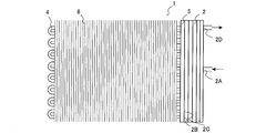
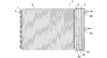
図1は、実施の形態1に係る熱交換器の、構成を示す図である。
図1に示されるように、熱交換器1は、積層型ヘッダー2と、ヘッダー3と、複数の第1伝熱管4と、保持部材5と、複数のフィン6と、を有する。
The heat exchanger according to
<Configuration of heat exchanger>
Below, the structure of the heat exchanger which concerns on
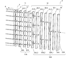
FIG. 1 is a diagram illustrating a configuration of a heat exchanger according to the first embodiment.
As shown in FIG. 1, the
以下に、実施の形態1に係る熱交換器における冷媒の流れについて説明する。
冷媒配管を流れる冷媒は、冷媒流入部2Aを介して積層型ヘッダー2に流入して分配され、複数の冷媒流出部2Bを介して複数の第1伝熱管4に流出する。冷媒は、複数の第1伝熱管4において、例えば、ファンによって供給される空気等と熱交換する。複数の第1伝熱管4を流れる冷媒は、複数の冷媒流入部3Aを介してヘッダー3に流入して合流し、冷媒流出部3Bを介して冷媒配管に流出する。冷媒は、逆流することができる。 <Flow of refrigerant in heat exchanger>
Below, the flow of the refrigerant in the heat exchanger according to
The refrigerant flowing through the refrigerant pipe flows into the
以下に、実施の形態1に係る熱交換器の積層型ヘッダーの構成について説明する。
図2は、実施の形態1に係る熱交換器の、積層型ヘッダーを分解した状態での斜視図である。
図2に示されるように、積層型ヘッダー2は、第1板状体11と、第2板状体12と、を有する。第1板状体11と第2板状体12とは、積層される。 <Configuration of laminated header>
Below, the structure of the laminated header of the heat exchanger which concerns on
FIG. 2 is a perspective view of the heat exchanger according to
As shown in FIG. 2, the
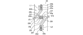
図3に示されるように、第3板状部材23に形成された流路23Aは、第1直線部23aの下端23cと第2直線部23dの上端23fとの間を、第3直線部23gを介して結ぶ形状である。第1直線部23a及び第2直線部23dは、重力方向と平行である。第3直線部23gは、重力方向と垂直である。第3直線部23gは、重力方向と垂直な状態から傾けられていてもよい。流路23Aが、冷媒の流入側に隣接して積層される部材によって、第3直線部23gの端部23hと端部23iとの間の一部の領域23j(以降、開口部23jという)以外の領域を閉塞され、冷媒の流出側に隣接して積層される部材によって、第1直線部23aの上端23b及び第2直線部23dの下端23e以外の領域を閉塞されることで、分岐流路12bが形成される。 FIG. 3 is a development view of the stacked header of the heat exchanger according to the first embodiment.
As shown in FIG. 3, the
図4に示されるように、第1伝熱管4の配列方向が、重力方向と平行ではない、つまり重力方向と交差する場合には、第3板状部材23の長手方向と第3直線部23gとが垂直にならない。つまり、積層型ヘッダー2は、複数の第1出口流路11Aが、重力方向に沿って配列されるものに限定されず、例えば、壁掛けタイプのルームエアコン室内機、空調機用室外機、チラー室外機等の熱交換器のように、熱交換器1が傾斜して配設される場合に用いられてもよい。なお、図4では、第1板状部材21に形成された流路21Aの断面の長手方向、つまり、第1出口流路11Aの断面の長手方向が、第1板状部材21の長手方向と垂直である場合を示しているが、第1出口流路11Aの断面の長手方向が、重力方向と垂直であってもよい。 FIG. 4 is a development view of the stacked header of the heat exchanger according to the first embodiment.
As shown in FIG. 4, when the arrangement direction of the first
図5に示されるように、流路23Aは、第3直線部23gを有しなくてもよい。つまり、接続部23kの第1直線部23aの下端23cに繋がらない側の端部、及び、接続部23lの第2直線部23dの上端23fに繋がらない側の端部が、開口部23jに直接繋がっていてもよい。また、接続部23kの開口部23jに繋がる側の端部、及び、接続部23lの開口部23jに繋がる側の端部は、重力方向と垂直でなくてもよい。第3直線部23gを有しない場合でも、第1直線部23a及び第2直線部23dを有することによって、冷媒の分配の均一性を向上することができる。第3直線部23gを有する場合には、冷媒の分配の均一性が更に向上される。 5 and 6 are diagrams showing a modification of the flow path formed in the third plate-like member of the heat exchanger according to
As shown in FIG. 5, the
以下に、実施の形態1に係る熱交換器の積層型ヘッダーにおける冷媒の流れについて説明する。
図3及び図4に示されるように、第2板状部材22の流路22Aを通過した冷媒は、第3板状部材23_1に形成された流路23Aの開口部23jに流入する。開口部23jに流入した冷媒は、隣接して積層される部材の表面に当たり、第3直線部23gの端部23hと端部23iとのそれぞれに向かって2つに分岐する。分岐された冷媒は、流路23Aの接続部23k、23lを介して、流路23Aの第1直線部23aの下端23c及び第2直線部23dの上端23fに流入して、流路23Aの第1直線部23aの上端23b及び第2直線部23dの下端23eに至り、第3板状部材23_2に形成された流路23Aの開口部23jに流入する。 <Refrigerant flow in stacked header>
Hereinafter, the flow of the refrigerant in the stacked header of the heat exchanger according to
As shown in FIGS. 3 and 4, the refrigerant that has passed through the
以下に、実施の形態1に係る熱交換器の積層型ヘッダーの各板状部材の積層方法について説明する。
各板状部材は、ロウ付け接合によって積層されるとよい。全ての板状部材又は1つおきの板状部材に、ロウ材が両面に圧延加工された両側クラッド材が用いられることで、接合のためのロウ材が供給されてもよい。全ての板状部材に、ロウ材が片面に圧延加工された片側クラッド材が用いられることで、接合のためのロウ材が供給されてもよい。各板状部材の間に、ロウ材シートが積層されることで、ロウ材が供給されてもよい。各板状部材の間に、ペースト状のロウ材が塗布されることで、ロウ材が供給されてもよい。各板状部材の間に、ロウ材が両面に圧延加工された両側クラッド材が積層されることで、ロウ材が供給されてもよい。 <Lamination method of plate members>
Below, the lamination | stacking method of each plate-shaped member of the lamination type header of the heat exchanger which concerns on
Each plate-like member is preferably laminated by brazing joint. A brazing material for joining may be supplied by using a double-sided clad material obtained by rolling a brazing material on both sides for all plate-like members or every other plate-like member. A brazing material for joining may be supplied to all the plate-like members by using a one-side clad material in which the brazing material is rolled on one side. The brazing material sheet may be supplied by laminating brazing material sheets between the plate-like members. The brazing material may be supplied by applying a pasty brazing material between the plate members. The brazing material may be supplied by laminating clad materials obtained by rolling the brazing material on both sides between the plate-like members.
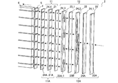
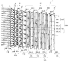
特に、各板状部材の間に、ロウ材が両面に圧延加工された板状部材、つまり両側クラッド材が積層されることで、ロウ材が供給されるとよい。図7及び図8に示されるように、複数の両側クラッド材24_1~24_5が、各板状部材間に積層される。以下では、複数の両側クラッド材24_1~24_5を総称して、両側クラッド材24と記載する場合がある。なお、一部の板状部材の間に、両側クラッド材24が積層され、他の板状部材の間に、他の方法によってロウ材が供給されてもよい。 FIG. 7 is a perspective view of the heat exchanger according to
In particular, a brazing material is preferably supplied by laminating a platy member obtained by rolling a brazing material on both sides, that is, clad materials on both sides, between the respective platy members. As shown in FIG. 7 and FIG. 8, a plurality of clad members 24_1 to 24_5 are laminated between the respective plate members. Hereinafter, the plurality of both-side clad materials 24_1 to 24_5 may be collectively referred to as the both-side clad
図9及び図10は、実施の形態1に係る熱交換器の、第3板状部材に形成される流路を示す図である。なお、図9及び図10では、隣接して積層される部材に形成される流路の一部を点線で示している。図9は、両側クラッド材24が積層されない状態(図2及び図3の状態)での、第3板状部材23に形成される流路23Aを示し、図10は、両側クラッド材24が積層される状態(図7及び図8の状態)での、第3板状部材23に形成される流路23Aを示している。 <Shape of the flow path of the third plate member>
9 and 10 are diagrams showing the flow path formed in the third plate member of the heat exchanger according to the first embodiment. In FIGS. 9 and 10, a part of the flow path formed in the members stacked adjacent to each other is indicated by a dotted line. 9 shows a
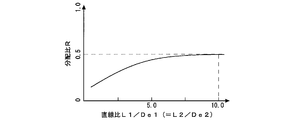
図11に示されるように、分配比Rは、直線比L1/De1と直線比L2/De2とが、10.0になるまで増加し、10.0以上で0.5になるように変化する。直線比L1/De1と直線比L2/De2とが10.0未満であると、接続部23k、23lが、重力方向と平行ではないことに起因して、冷媒が次の流路23Aの第3直線部23gに偏流を生じた状態で流入することになり、分配比Rが0.5にならない。 FIG. 11 is a diagram illustrating a relationship between a linear ratio and a distribution ratio of the first linear portion and the second linear portion of the flow path formed in the third plate member of the heat exchanger according to the first embodiment. is there. In FIG. 11, the linear ratio L1 / De1 = the linear ratio L2 / De2, and the linear ratio L1 / De1 (= L2 / De2) of the
As shown in FIG. 11, the distribution ratio R increases until the linear ratio L1 / De1 and the linear ratio L2 / De2 increase to 10.0, and changes so as to be 0.5 at 10.0 or more. . If the linear ratio L1 / De1 and the linear ratio L2 / De2 are less than 10.0, the connecting
図14に示されるように、分配比Rは、直線比L3/De3と直線比L4/De4とが、1.0になるまで増加し、1.0以上で0.5になるように変化する。直線比L3/De3と直線比L4/De4とが1.0未満であると、接続部23kの第3直線部23gの端部23hに連通する領域と、接続部23lの第3直線部23gの端部23iに連通する領域と、が、重力方向に対する方向が異なるように折り曲げられることの影響を受け、分配比Rが0.5にならない。すなわち、直線比L3/De3と直線比L4/De4とを、1.0以上にすることで、冷媒の分配の均一性を更に向上することができる。 FIG. 14 is a diagram illustrating the relationship between the linear ratio of the third linear portion and the distribution ratio of the flow path formed in the third plate-like member of the heat exchanger according to the first embodiment. FIG. 14 shows a distribution ratio R in the
As shown in FIG. 14, the distribution ratio R increases until the linear ratio L3 / De3 and the linear ratio L4 / De4 increase to 1.0, and changes to 0.5 when 1.0 or more. . When the linear ratio L3 / De3 and the linear ratio L4 / De4 are less than 1.0, the region communicating with the
図15に示されるように、角度θ1と角度θ2とが90°に近づく程、分配比Rは0.5に近づく。すなわち、角度θ1と角度θ2とを、大きくすることで、冷媒の分配の均一性を更に向上することができる。特に、図6に示されるように、流路23Aが、第1直線部23aの下端23cが第3直線部23gの端部23hに近接し、第2直線部23dの上端23fが第3直線部23gの端部23iに近接するものである場合には、冷媒の分配の均一性が更に向上する。 FIG. 15 is a diagram illustrating the relationship between the bending angle of the connecting portion and the distribution ratio of the flow path formed in the third plate-like member of the heat exchanger according to the first embodiment. FIG. 15 shows a change in the distribution ratio R in the
As shown in FIG. 15, the distribution ratio R approaches 0.5 as the angle θ1 and the
以下に、実施の形態1に係る熱交換器の使用態様の一例について説明する。
なお、以下では、実施の形態1に係る熱交換器が空気調和装置に使用される場合を説明しているが、そのような場合に限定されず、例えば、冷媒循環回路を有する他の冷凍サイクル装置に使用されてもよい。また、空気調和装置が、冷房運転と暖房運転とを切り替えるものである場合を説明しているが、そのような場合に限定されず、冷房運転又は暖房運転のみを行うものであってもよい。 <Usage of heat exchanger>
Below, an example of the usage aspect of the heat exchanger which concerns on
In addition, although the case where the heat exchanger which concerns on
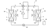
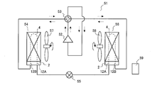
図16に示されるように、空気調和装置51は、圧縮機52と、四方弁53と、熱源側熱交換器54と、絞り装置55と、負荷側熱交換器56と、熱源側ファン57、負荷側ファン58、制御装置59と、を有する。圧縮機52と四方弁53と熱源側熱交換器54と絞り装置55と負荷側熱交換器56とが冷媒配管で接続されて、冷媒循環回路が形成される。 FIG. 16 is a diagram illustrating a configuration of an air-conditioning apparatus to which the heat exchanger according to
As shown in FIG. 16, the
圧縮機52から吐出される高圧高温のガス状態の冷媒は、四方弁53を介して熱源側熱交換器54に流入し、熱源側ファン57によって供給される外気との熱交換によって凝縮することで高圧の液状態の冷媒となり、熱源側熱交換器54から流出する。熱源側熱交換器54から流出した高圧の液状態の冷媒は、絞り装置55に流入し、低圧の気液二相状態の冷媒となる。絞り装置55から流出する低圧の気液二相状態の冷媒は、負荷側熱交換器56に流入し、負荷側ファン58によって供給される室内空気との熱交換によって蒸発することで低圧のガス状態の冷媒となり、負荷側熱交換器56から流出する。負荷側熱交換器56から流出する低圧のガス状態の冷媒は、四方弁53を介して圧縮機52に吸入される。 The flow of the refrigerant during the cooling operation will be described.
The high-pressure and high-temperature gas refrigerant discharged from the
圧縮機52から吐出される高圧高温のガス状態の冷媒は、四方弁53を介して負荷側熱交換器56に流入し、負荷側ファン58によって供給される室内空気との熱交換によって凝縮することで高圧の液状態の冷媒となり、負荷側熱交換器56から流出する。負荷側熱交換器56から流出した高圧の液状態の冷媒は、絞り装置55に流入し、低圧の気液二相状態の冷媒となる。絞り装置55から流出する低圧の気液二相状態の冷媒は、熱源側熱交換器54に流入し、熱源側ファン57によって供給される外気との熱交換によって蒸発することで低圧のガス状態の冷媒となり、熱源側熱交換器54から流出する。熱源側熱交換器54から流出する低圧のガス状態の冷媒は、四方弁53を介して圧縮機52に吸入される。 The flow of the refrigerant during the heating operation will be described.
The high-pressure and high-temperature gas refrigerant discharged from the
以下に、実施の形態1に係る熱交換器の作用について説明する。
積層型ヘッダー2の第2板状体12に、開口部23jと、下端23cが接続部23kを介して開口部23jに連通する、重力方向と平行な第1直線部23aと、上端23fが接続部23lを介して開口部23jに連通する、重力方向と平行な第2直線部23dと、を有する分岐流路12bを含む分配流路12Aが形成される。そして、分岐流路12bの開口部23jから流入した冷媒は、少なくとも一部が重力方向と平行ではない接続部23k、23lの通過に伴って生じる重力方向と垂直な方向での偏流が、第1直線部23a及び第2直線部23dで均一化された後に、第1直線部23aの上端23b及び第2直線部23dの下端23eから流出することとなる。そのため、冷媒が偏流を生じた状態で分岐流路12bから流出することが抑制され、冷媒の分配の均一性が向上される。 <Operation of heat exchanger>
Below, the effect | action of the heat exchanger which concerns on
Connected to the second plate-
図17は、実施の形態1に係る熱交換器の変形例-1の、積層型ヘッダーを分解した状態での斜視図である。なお、図17以下の図面では、両側クラッド材24が積層される状態(図7及び図8の状態)を示しているが、両側クラッド材24が積層されない状態(図2及び図3の状態)であってもよいことは、言うまでもない。
図17に示されるように、第2板状部材22に流路22Aが複数形成されて、つまり、第2板状体12に第1入口流路12aが複数形成されて、第3板状部材23の枚数が削減されてもよい。このように構成されることで、部品費、重量等が削減される。 <Modification-1>
FIG. 17 is a perspective view of a modified example-1 of the heat exchanger according to
As shown in FIG. 17, a plurality of
複数の流路22Aが、第3板状部材23に形成される流路23Aの冷媒が流入する領域と対向する領域に設けられなくてもよい。図18に示されるように、例えば、複数の流路22Aが一箇所に纏めて形成され、第2板状部材22と第3板状部材23_1との間に積層される他の板状部材25の流路25Aによって、複数の流路22Aを通過した冷媒のそれぞれが、第3板状部材23に形成される流路23Aの冷媒が流入する領域と対向する領域に導かれてもよい。 FIG. 18 is a perspective view of a modified example-1 of the heat exchanger according to
The plurality of
図19は、実施の形態1に係る熱交換器の変形例-2の、積層型ヘッダーを分解した状態での斜視図である。
図19に示されるように、第3板状部材23のいずれか1つが、開口部23jが第3直線部23gに位置しない流路25Bが形成された他の板状部材25に、置き換えられてもよい。例えば、流路25Bは、開口部23jが第3直線部23gではなく交差部に位置し、冷媒はその交差部に流入して4つに分岐する。分岐の数は、どのような数でもよい。分岐の数が多い程、第3板状部材23の枚数が削減される。このように構成されることで、冷媒の分配の均一性は低下してしまうものの、部品費、重量等が削減される。 <Modification-2>
FIG. 19 is a perspective view of a
As shown in FIG. 19, any one of the third plate-
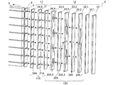
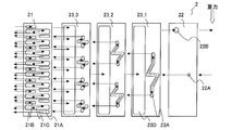
図20は、実施の形態1に係る熱交換器の変形例-3の、積層型ヘッダーを分解した状態での斜視図である。図21は、実施の形態1に係る熱交換器の変形例-3の、積層型ヘッダーの展開図である。なお、図21では、両側クラッド材24の図示が省略されている。
図20及び図21に示されるように、第3板状部材23のいずれか1つ(例えば、第3板状部材23_2)が、冷媒を第1板状体11が有る側に折り返さずに流出する分岐流路12bとして機能する流路23Aと、冷媒を第1板状体11が有る側の反対側に折り返して流出する分岐流路12bとして機能する流路23Bと、を有してもよい。流路23Bは、流路23Aと同様の構成である。つまり、流路23Bは、重力方向と平行な第1直線部23aと第2直線部23dを有し、冷媒は、流路23Bにおいて、開口部23jから流入し、第1直線部23aの上端23b及び第2直線部23dの下端23eから流出する。このように構成されることで、第3板状部材23の枚数が削減され、部品費、重量等が削減される。また、ロウ付け不良の発生の頻度が削減される。 <Modification-3>
FIG. 20 is a perspective view of the
As shown in FIGS. 20 and 21, any one of the third plate-like members 23 (for example, the third plate-like member 23_2) flows out the refrigerant without being folded back to the side where the first plate-
図22は、実施の形態1に係る熱交換器の変形例-4の、積層型ヘッダーを分解した状態での斜視図である。
図22に示されるように、板状部材及び両側クラッド材24のいずれか、つまり積層される部材のいずれかの表面に、凸部26が形成されてもよい。凸部26は、例えば、位置、形状、大きさ等が、積層される部材毎に固有である。凸部26は、スペーサ等の部品であってもよい。隣接して積層される部材には、凸部26が挿入される凹部27が形成される。凹部27は、貫通穴であってもよく、そうでなくてもよい。このように構成されることで、積層される部材の積層順序を間違うことが抑制され、不良率が低減される。凸部26と凹部27とが嵌合してもよい。そのような場合には、凸部26と凹部27とが、複数形成され、積層される部材がその嵌合によって位置決めされてもよい。また、凹部27が形成されず、凸部26が、隣接して積層される部材に形成される流路の一部に挿入されてもよい。そのような場合には、凸部26の高さ、大きさ等を、冷媒の流れを妨げない程度とすればよい。 <
FIG. 22 is a perspective view of
As shown in FIG. 22, a
図23は、実施の形態1に係る熱交換器の変形例-5の、積層型ヘッダーを分解した状態での要部の斜視図である。図24は、実施の形態1に係る熱交換器の変形例-5の、積層型ヘッダーを分解した状態での要部の断面図である。なお、図24は、図23のA-A線での第1板状部材21の断面図である。
図23及び図24に示されるように、第1板状部材21に形成された複数の流路21Aのいずれかが、第1板状部材21の第2板状体12の有る側の表面で円形状になり、第1板状部材21の保持部材5の有る側の表面で第1伝熱管4の外周面に沿う形状になる、テーパ状の貫通穴であってもよい。特に、第1伝熱管4が扁平管である場合には、その貫通穴は、第2板状体12の有る側の表面から保持部材5の有る側の表面に至るまでの間で、徐々に広がる形状となる。このように構成されることで、第1出口流路11Aを通過する際の冷媒の圧力損失が低減される。 <Modification-5>
FIG. 23 is a perspective view of an essential part of a modified example-5 of the heat exchanger according to
As shown in FIGS. 23 and 24, any one of the plurality of
図25は、実施の形態1に係る熱交換器の変形例-6の、積層型ヘッダーを分解した状態での要部の斜視図である。図26は、実施の形態1に係る熱交換器の変形例-6の、積層型ヘッダーを分解した状態での要部の断面図である。なお、図26は、図25のB-B線での第3板状部材23の断面図である。
図25及び図26に示されるように、第3板状部材23に形成された流路23Aのいずれかが、有底の溝であってもよい。そのような場合には、流路23Aの溝の底面の端部23oと端部23pとのそれぞれに円形状の貫通穴23qが形成される。このように構成されることで、分岐流路12b間に冷媒隔離流路として機能する流路24Aを介在させるために、板状部材間に両側クラッド材24が積層されなくてもよくなり、生産効率が向上される。なお、図25及び図26では、流路23Aの冷媒の流出側が底面である場合を示しているが、流路23Aの冷媒の流入側が底面であってもよい。そのような場合には、開口部23jに相当する領域に貫通穴が形成されればよい。 <Modification-6>
FIG. 25 is a perspective view of an essential part of a
As shown in FIGS. 25 and 26, any of the
図27は、実施の形態1に係る熱交換器の変形例-7の、積層型ヘッダーを分解した状態での斜視図である。
図27に示されるように、第1入口流路12aとして機能する流路22Aは、第2板状部材22以外の積層される部材、つまり、他の板状部材、両側クラッド材24等に形成されてもよい。そのような場合には、流路22Aを、例えば、他の板状部材の側面から第2板状部材22の有る側の表面までを貫通する貫通穴とすればよい。つまり、本発明は、第1入口流路12aが第1板状体11に形成されるものを含み、本発明の「分配流路」は、第1入口流路12aが第2板状体12に形成される分配流路12A以外を含む。 <Modification-7>
FIG. 27 is a perspective view of Modified Example-7 of the heat exchanger according to
As shown in FIG. 27, the
実施の形態2に係る熱交換器について説明する。
なお、実施の形態1と重複又は類似する説明は、適宜簡略化又は省略している。
<熱交換器の構成>
以下に、実施の形態2に係る熱交換器の構成について説明する。
図28は、実施の形態2に係る熱交換器の、構成を示す図である。
図28に示されるように、熱交換器1は、積層型ヘッダー2と、複数の第1伝熱管4と、保持部材5と、複数のフィン6と、を有する。
A heat exchanger according to
Note that description overlapping or similar to that in
<Configuration of heat exchanger>
Below, the structure of the heat exchanger which concerns on
FIG. 28 is a diagram illustrating a configuration of a heat exchanger according to the second embodiment.
As shown in FIG. 28, the
以下に、実施の形態2に係る熱交換器における冷媒の流れについて説明する。
冷媒配管を流れる冷媒は、冷媒流入部2Aを介して積層型ヘッダー2に流入して分配され、複数の冷媒流出部2Bを介して複数の第1伝熱管4に流出する。冷媒は、複数の第1伝熱管4において、例えば、ファンによって供給される空気等と熱交換する。複数の第1伝熱管4を通過した冷媒は、複数の冷媒流入部2Cを介して積層型ヘッダー2に流入して合流し、冷媒流出部2Dを介して冷媒配管に流出する。冷媒は、逆流することができる。 <Flow of refrigerant in heat exchanger>
Below, the flow of the refrigerant in the heat exchanger according to the second embodiment will be described.
The refrigerant flowing through the refrigerant pipe flows into the
以下に、実施の形態2に係る熱交換器の積層型ヘッダーの構成について説明する。
図29は、実施の形態2に係る熱交換器の、積層型ヘッダーを分解した状態での斜視図である。図30は、実施の形態2に係る熱交換器の、積層型ヘッダーの展開図である。なお、図30では、両側クラッド材24の図示が省略されている。
図29及び図30に示されるように、積層型ヘッダー2は、第1板状体11と、第2板状体12と、を有する。第1板状体11と第2板状体12とは、積層される。 <Configuration of laminated header>
Below, the structure of the laminated header of the heat exchanger which concerns on
FIG. 29 is a perspective view of the heat exchanger according to
As shown in FIGS. 29 and 30, the
以下に、実施の形態2に係る熱交換器の積層型ヘッダーにおける冷媒の流れについて説明する。
図29及び図30に示されるように、第1板状部材21の流路21Aから流出して第1伝熱管4を通過した冷媒は、第1板状部材21の流路21Bに流入する。第1板状部材21の流路21Bに流入した冷媒は、第3板状部材23に形成された流路23Dに流入して混合される。混合された冷媒は、第2板状部材22の流路22Bを通過して、冷媒配管に流出する。 <Refrigerant flow in stacked header>
Below, the flow of the refrigerant in the stacked header of the heat exchanger according to
As shown in FIGS. 29 and 30, the refrigerant that has flowed out of the
以下に、実施の形態2に係る熱交換器の使用態様の一例について説明する。
図31は、実施の形態2に係る熱交換器が適用される空気調和装置の、構成を示す図である。
図31に示されるように、熱源側熱交換器54及び負荷側熱交換器56の少なくともいずれか一方に、熱交換器1が用いられる。熱交換器1は、熱交換器1が蒸発器として作用する際に、積層型ヘッダー2の分配流路12Aから第1伝熱管4に冷媒が流入し、第1伝熱管4から積層型ヘッダー2の合流流路12Bに冷媒が流入するように接続される。つまり、熱交換器1が蒸発器として作用する際は、冷媒配管から積層型ヘッダー2の分配流路12Aに気液二相状態の冷媒が流入し、第1伝熱管4から積層型ヘッダー2の合流流路12Bにガス状態の冷媒が流入する。また、熱交換器1が凝縮器として作用する際は、冷媒配管から積層型ヘッダー2の合流流路12Bにガス状態の冷媒が流入し、第1伝熱管4から積層型ヘッダー2の分配流路12Aに液状態の冷媒が流入する。 <Usage of heat exchanger>
Below, an example of the usage condition of the heat exchanger which concerns on
FIG. 31 is a diagram illustrating a configuration of an air-conditioning apparatus to which the heat exchanger according to
As shown in FIG. 31, the
以下に、実施の形態2に係る熱交換器の作用について説明する。
積層型ヘッダー2では、第1板状体11に複数の第2入口流路11Bが形成され、第2板状体12に合流流路12Bが形成される。そのため、ヘッダー3が不要となって、熱交換器1の部品費等が削減される。また、ヘッダー3が不要となる分、第1伝熱管4を延長してフィン6の枚数等を増加する、つまり熱交換器1の熱交換部の実装体積を増加することが可能となる。 <Operation of heat exchanger>
Below, the effect | action of the heat exchanger which concerns on
In the
実施の形態3に係る熱交換器について説明する。
なお、実施の形態1及び実施の形態2と重複又は類似する説明は、適宜簡略化又は省略している。
<熱交換器の構成>
以下に、実施の形態3に係る熱交換器の構成について説明する。
図32は、実施の形態3に係る熱交換器の、構成を示す図である。
図32に示されるように、熱交換器1は、積層型ヘッダー2と、複数の第1伝熱管4と、複数の第2伝熱管7と、保持部材5と、複数のフィン6と、を有する。
A heat exchanger according to
Note that the description overlapping or similar to the first embodiment and the second embodiment is appropriately simplified or omitted.
<Configuration of heat exchanger>
Below, the structure of the heat exchanger which concerns on
FIG. 32 is a diagram illustrating a configuration of a heat exchanger according to the third embodiment.
As shown in FIG. 32, the
以下に、実施の形態3に係る熱交換器における冷媒の流れについて説明する。
冷媒配管を流れる冷媒は、冷媒流入部2Aを介して積層型ヘッダー2に流入して分配され、複数の冷媒流出部2Bを介して複数の第1伝熱管4に流出する。冷媒は、複数の第1伝熱管4において、例えば、ファンによって供給される空気等と熱交換する。複数の第1伝熱管4を通過した冷媒は、積層型ヘッダー2の複数の冷媒折返部2Eに流入して折り返され、複数の第2伝熱管7に流出する。冷媒は、複数の第2伝熱管7において、例えば、ファンによって供給される空気等と熱交換する。複数の第2伝熱管7を通過した冷媒は、複数の冷媒流入部2Cを介して積層型ヘッダー2に流入して合流し、冷媒流出部2Dを介して冷媒配管に流出する。冷媒は、逆流することができる。 <Flow of refrigerant in heat exchanger>
Below, the flow of the refrigerant in the heat exchanger according to
The refrigerant flowing through the refrigerant pipe flows into the
以下に、実施の形態3に係る熱交換器の積層型ヘッダーの構成について説明する。
図33は、実施の形態3に係る熱交換器の、積層型ヘッダーを分解した状態での斜視図である。図34は、実施の形態3に係る熱交換器の、積層型ヘッダーの展開図である。なお、図34では、両側クラッド材24の図示が省略されている。
図33及び図34に示されるように、積層型ヘッダー2は、第1板状体11と、第2板状体12と、を有する。第1板状体11と第2板状体12とは、積層される。 <Configuration of laminated header>
Below, the structure of the laminated header of the heat exchanger which concerns on
FIG. 33 is a perspective view of the heat exchanger according to
As shown in FIGS. 33 and 34, the
以下に、実施の形態3に係る熱交換器の積層型ヘッダーにおける冷媒の流れについて説明する。
図33及び図34に示されるように、第1板状部材21の流路21Aから流出して第1伝熱管4を通過した冷媒は、第1板状部材21の流路21Cに流入し、折り返されて、第2伝熱管7に流入する。第2伝熱管7を通過した冷媒は、第1板状部材21の流路21Bに流入する。第1板状部材21の流路21Bに流入した冷媒は、第3板状部材23に形成された流路23Dに流入して混合される。混合された冷媒は、第2板状部材22の流路22Bを通過して、冷媒配管に流出する。 <Refrigerant flow in stacked header>
The refrigerant flow in the stacked header of the heat exchanger according to
As shown in FIGS. 33 and 34, the refrigerant that has flowed out of the
以下に、実施の形態3に係る熱交換器の使用態様の一例について説明する。
図35は、実施の形態3に係る熱交換器が適用される空気調和装置の、構成を示す図である。
図35に示されるように、熱源側熱交換器54及び負荷側熱交換器56の少なくともいずれか一方に、熱交換器1が用いられる。熱交換器1は、熱交換器1が蒸発器として作用する際に、積層型ヘッダー2の分配流路12Aから第1伝熱管4に冷媒が流入し、第2伝熱管7から積層型ヘッダー2の合流流路12Bに冷媒が流入するように接続される。つまり、熱交換器1が蒸発器として作用する際は、冷媒配管から積層型ヘッダー2の分配流路12Aに気液二相状態の冷媒が流入し、第2伝熱管7から積層型ヘッダー2の合流流路12Bにガス状態の冷媒が流入する。また、熱交換器1が凝縮器として作用する際は、冷媒配管から積層型ヘッダー2の合流流路12Bにガス状態の冷媒が流入し、第1伝熱管4から積層型ヘッダー2の分配流路12Aに液状態の冷媒が流入する。 <Usage of heat exchanger>
Below, an example of the usage mode of the heat exchanger which concerns on
FIG. 35 is a diagram illustrating a configuration of an air-conditioning apparatus to which the heat exchanger according to
As shown in FIG. 35, the
以下に、実施の形態3に係る熱交換器の作用について説明する。
熱交換器1では、第1板状体11に複数の折返流路11Cが形成され、複数の第1伝熱管4に加えて、複数の第2伝熱管7が接続される。例えば、熱交換器1の正面視した状態での面積を増加させて、熱交換量を増やすことも可能であるが、その場合には、熱交換器1を内蔵する筐体が大型化されてしまう。また、フィン6の間隔を小さくして、フィン6の枚数を増加させて、熱交換量を増やすことも可能であるが、その場合には、排水性、着霜性能、埃耐力の観点から、フィン6の間隔を約1mm未満にすることが困難であり、熱交換量の増加が不充分となってしまう場合がある。一方、熱交換器1のように、伝熱管の列数を増加させる場合には、熱交換器1の正面視した状態での面積、フィン6の間隔等を変えることなく、熱交換量を増加させることが可能である。伝熱管の列数が2列になると、熱交換量は約1.5倍以上に増加する。なお、伝熱管の列数が3列以上にされてもよい。また、更に、熱交換器1の正面視した状態での面積、フィン6の間隔等が変えられてもよい。 <Operation of heat exchanger>
Below, the effect | action of the heat exchanger which concerns on
In the
Claims (15)
- 複数の第1出口流路が形成された第1板状体と、
前記第1板状体に取り付けられ、第1入口流路から流入する冷媒を前記複数の第1出口流路に分配して流出する分配流路が形成された第2板状体と、を備え、
前記分配流路は、
開口部と、
下端が第1接続部を介して前記開口部に連通する、重力方向と平行な第1直線部と、
上端が第2接続部を介して前記開口部に連通する、重力方向と平行な第2直線部と、を有する分岐流路を含み、
前記第1接続部の少なくとも一部及び前記第2接続部の少なくとも一部は、重力方向と平行ではなく、
前記分岐流路において、前記冷媒は、前記開口部から前記第1接続部及び前記第2接続部を介して前記第1直線部の下端及び前記第2直線部の上端に流入し、前記第1直線部の上端及び前記第2直線部の下端から流出する、積層型ヘッダー。 A first plate-like body formed with a plurality of first outlet channels;
A second plate-like body attached to the first plate-like body and formed with a distribution channel for distributing the refrigerant flowing in from the first inlet channel to the plurality of first outlet channels and flowing out. ,
The distribution channel is
An opening,
A first linear portion parallel to the direction of gravity, the lower end of which communicates with the opening through a first connection portion;
A branch flow path having a second straight portion parallel to the direction of gravity, the upper end of which communicates with the opening via a second connection portion;
At least a part of the first connection part and at least a part of the second connection part are not parallel to the direction of gravity,
In the branch channel, the refrigerant flows from the opening into the lower end of the first straight portion and the upper end of the second straight portion through the first connection portion and the second connection portion, A stacked header that flows out from an upper end of a straight portion and a lower end of the second straight portion. - 前記第1直線部及び前記第2直線部のそれぞれは、前記上端から前記下端までの流路の長さが、該流路の水力相当直径と比較して3倍以上である、請求項1に記載の積層型ヘッダー。 In each of the first straight part and the second straight part, the length of the flow path from the upper end to the lower end is three times or more compared to the hydraulic equivalent diameter of the flow path. The laminated header described.
- 前記分岐流路は、重力方向と垂直な第3直線部を有し、
前記開口部は、前記第3直線部の両端の間の一部である、請求項1または2に記載の積層型ヘッダー。 The branch flow path has a third straight portion perpendicular to the direction of gravity,
The stacked header according to claim 1, wherein the opening is a part between both ends of the third straight portion. - 前記第3直線部は、前記開口部の中心から該第3直線部の前記両端のそれぞれまでの流路の長さが、該流路の水力相当直径と比較して1倍以上である、請求項3に記載の積層型ヘッダー。 The third straight part has a length of a flow path from the center of the opening to each of the both ends of the third straight part, which is one or more times larger than a hydraulic equivalent diameter of the flow path. Item 4. The laminated header according to Item 3.
- 前記第2板状体は、流路が形成された少なくとも1つの板状部材を有し、
前記分岐流路は、前記板状部材に形成された流路の、前記冷媒が流入する領域及び前記冷媒が流出する領域以外の領域が、前記板状部材に隣接して取り付けられた部材によって閉塞されたものである、請求項1~4のいずれか一項に記載の積層型ヘッダー。 The second plate-like body has at least one plate-like member in which a flow path is formed,
The branch flow path is closed by a member attached adjacent to the plate-like member, except for a region where the refrigerant flows and a region where the refrigerant flows out of the flow channel formed in the plate-like member. The multilayer header according to any one of claims 1 to 4, wherein - 前記第1直線部の前記上端及び前記第2直線部の前記下端の配列方向は、前記複数の第1出口流路の配列方向に沿う、請求項1~5のいずれか一項に記載の積層型ヘッダー。 The stacking direction according to any one of claims 1 to 5, wherein an arrangement direction of the upper end of the first straight portion and the lower end of the second straight portion is along the arrangement direction of the plurality of first outlet channels. Type header.
- 前記第1入口流路は、複数である、請求項1~6のいずれか一項に記載の積層型ヘッダー。 The multi-layer header according to any one of claims 1 to 6, wherein the first inlet channel is plural.
- 前記分岐流路は、前記冷媒が前記第1板状体の有る側に流出する分岐流路と、前記冷媒が前記第1板状体の有る側の反対側に流出する分岐流路と、である、請求項1~7のいずれか一項に記載の積層型ヘッダー。 The branch flow path includes a branch flow path through which the refrigerant flows out to the side having the first plate-like body, and a branch flow path from which the refrigerant flows out to the side opposite to the side having the first plate-like body. The multi-layer header according to any one of claims 1 to 7, wherein:
- 前記板状部材には、該板状部材固有の凸部が形成され、
前記凸部は、前記板状部材に隣接して取り付けられた部材に形成された流路に挿入された、請求項5に記載の積層型ヘッダー。 The plate-like member has a protrusion unique to the plate-like member,
The multilayer header according to claim 5, wherein the convex portion is inserted into a flow path formed in a member attached adjacent to the plate-like member. - 請求項1~9のいずれか一項に記載の積層型ヘッダーと、
前記複数の第1出口流路のそれぞれに接続された複数の第1伝熱管と、を備えた熱交換器。 The laminated header according to any one of claims 1 to 9,
A heat exchanger comprising: a plurality of first heat transfer tubes connected to each of the plurality of first outlet channels. - 前記第1板状体に、前記複数の第1伝熱管を通過した前記冷媒が流入する複数の第2入口流路が形成され、
前記第2板状体に、前記複数の第2入口流路から流入する前記冷媒を合流して第2出口流路に流入させる合流流路が形成された、請求項10に記載の熱交換器。 A plurality of second inlet flow paths into which the refrigerant that has passed through the plurality of first heat transfer tubes flows are formed in the first plate-like body,
11. The heat exchanger according to claim 10, wherein a merge flow path is formed in the second plate-like body to merge the refrigerant flowing in from the plurality of second inlet flow paths into the second outlet flow path. . - 前記第1伝熱管は、扁平管である、請求項10または11に記載の熱交換器。 The heat exchanger according to claim 10 or 11, wherein the first heat transfer tube is a flat tube.
- 前記第1出口流路の内周面は、前記第1伝熱管の外周面に向かって徐々に広がる、請求項12に記載の熱交換器。 The heat exchanger according to claim 12, wherein an inner peripheral surface of the first outlet channel gradually expands toward an outer peripheral surface of the first heat transfer tube.
- 請求項10~13のいずれか一項に記載の熱交換器を備え、
前記分配流路は、前記熱交換器が蒸発器として作用する際に、前記複数の第1出口流路に前記冷媒を流出する、空気調和装置。 A heat exchanger according to any one of claims 10 to 13,
The distribution channel is an air conditioner in which the refrigerant flows out to the plurality of first outlet channels when the heat exchanger acts as an evaporator. - 請求項1~9のいずれか一項に記載の積層型ヘッダーと、
前記複数の第1出口流路のそれぞれに接続された複数の第1伝熱管と、を有する熱交換器を備え、
前記積層型ヘッダーは、
前記第1板状体に、前記複数の第1伝熱管を通過した前記冷媒が流入する複数の第2入口流路が形成され、
前記第2板状体に、前記複数の第2入口流路から流入する前記冷媒を合流して第2出口流路に流入させる合流流路が形成され、
前記熱交換器は、前記複数の第2入口流路のそれぞれに接続された複数の第2伝熱管を有し、
前記分配流路は、前記熱交換器が蒸発器として作用する際に、前記複数の第1出口流路に前記冷媒を流出し、
前記第1伝熱管は、前記熱交換器が凝縮器として作用する際に、前記第2伝熱管と比較して、風上側に位置する、空気調和装置。
The laminated header according to any one of claims 1 to 9,
A heat exchanger having a plurality of first heat transfer tubes connected to each of the plurality of first outlet channels,
The laminated header is
A plurality of second inlet flow paths into which the refrigerant that has passed through the plurality of first heat transfer tubes flows are formed in the first plate-like body,
The second plate-like body is formed with a merge channel that merges the refrigerant flowing in from the plurality of second inlet channels and flows into the second outlet channel,
The heat exchanger has a plurality of second heat transfer tubes connected to each of the plurality of second inlet channels,
The distribution channel flows out the refrigerant into the plurality of first outlet channels when the heat exchanger acts as an evaporator,
When the said heat exchanger acts as a condenser, the said 1st heat exchanger tube is an air conditioning apparatus located in an upwind side compared with the said 2nd heat exchanger tube.
Priority Applications (9)
| Application Number | Priority Date | Filing Date | Title |
|---|---|---|---|
| CN201480024272.3A CN105164491B (en) | 2013-05-15 | 2014-05-13 | Laminated header, heat exchanger, and air conditioner |
| JP2015517079A JP6012857B2 (en) | 2013-05-15 | 2014-05-13 | Laminated header, heat exchanger, and air conditioner |
| KR1020157032420A KR101770493B1 (en) | 2013-05-15 | 2014-05-13 | Laminated header, heat exchanger, and air conditioner |
| BR112015028496-5A BR112015028496B1 (en) | 2013-05-15 | 2014-05-13 | stacking collector, heat exchanger, and air conditioning unit |
| EP14798366.2A EP2998683B1 (en) | 2013-05-15 | 2014-05-13 | Laminated header, heat exchanger, and air conditioner |
| AU2014266400A AU2014266400B2 (en) | 2013-05-15 | 2014-05-13 | Stacking-type header, heat exchanger, and air-conditioning apparatus |
| US14/785,703 US10077953B2 (en) | 2013-05-15 | 2014-05-13 | Stacking-type header, heat exchanger, and air-conditioning apparatus |
| CN201420249288.1U CN203940771U (en) | 2013-05-15 | 2014-05-15 | Cascade type collector, heat exchanger and aircondition |
| HK16105432.7A HK1217531A1 (en) | 2013-05-15 | 2016-05-12 | Laminated header, heat exchanger, and air conditioner |
Applications Claiming Priority (2)
| Application Number | Priority Date | Filing Date | Title |
|---|---|---|---|
| PCT/JP2013/063607 WO2014184915A1 (en) | 2013-05-15 | 2013-05-15 | Laminated header, heat exchanger, and air conditioner |
| JPPCT/JP2013/063607 | 2013-05-15 |
Publications (1)
| Publication Number | Publication Date |
|---|---|
| WO2014185391A1 true WO2014185391A1 (en) | 2014-11-20 |
Family
ID=51897925
Family Applications (2)
| Application Number | Title | Priority Date | Filing Date |
|---|---|---|---|
| PCT/JP2013/063607 WO2014184915A1 (en) | 2013-05-15 | 2013-05-15 | Laminated header, heat exchanger, and air conditioner |
| PCT/JP2014/062653 WO2014185391A1 (en) | 2013-05-15 | 2014-05-13 | Laminated header, heat exchanger, and air conditioner |
Family Applications Before (1)
| Application Number | Title | Priority Date | Filing Date |
|---|---|---|---|
| PCT/JP2013/063607 WO2014184915A1 (en) | 2013-05-15 | 2013-05-15 | Laminated header, heat exchanger, and air conditioner |
Country Status (9)
| Country | Link |
|---|---|
| US (1) | US10077953B2 (en) |
| EP (1) | EP2998683B1 (en) |
| JP (1) | JP6012857B2 (en) |
| KR (1) | KR101770493B1 (en) |
| CN (1) | CN105164491B (en) |
| AU (1) | AU2014266400B2 (en) |
| BR (1) | BR112015028496B1 (en) |
| HK (1) | HK1217531A1 (en) |
| WO (2) | WO2014184915A1 (en) |
Cited By (7)
| Publication number | Priority date | Publication date | Assignee | Title |
|---|---|---|---|---|
| WO2016071946A1 (en) * | 2014-11-04 | 2016-05-12 | 三菱電機株式会社 | Layered header, heat exchanger, and air-conditioning device |
| WO2016072100A1 (en) * | 2014-11-06 | 2016-05-12 | 住友精密工業株式会社 | Heat exchanger |
| WO2017042866A1 (en) * | 2015-09-07 | 2017-03-16 | 三菱電機株式会社 | Distributor, laminated header, heat exchanger, and air conditioner |
| WO2017175346A1 (en) * | 2016-04-07 | 2017-10-12 | 三菱電機株式会社 | Distributor, heat exchanger, and air conditioning device |
| JP2019504984A (en) * | 2016-02-03 | 2019-02-21 | リム, ジョンソLIM, Jongsoo | Heat exchanger |
| WO2020090015A1 (en) * | 2018-10-30 | 2020-05-07 | 三菱電機株式会社 | Refrigerant distributor, heat exchanger, and air conditioning device |
| JP2020173071A (en) * | 2019-04-11 | 2020-10-22 | 三菱重工サーマルシステムズ株式会社 | Header for heat exchanger, heat exchanger, and air conditioner |
Families Citing this family (17)
| Publication number | Priority date | Publication date | Assignee | Title |
|---|---|---|---|---|
| CN105683701A (en) * | 2013-10-29 | 2016-06-15 | 三菱电机株式会社 | Heat exchanger and air conditioner |
| US11421947B2 (en) * | 2015-09-07 | 2022-08-23 | Mitsubishi Electric Corporation | Laminated header, heat exchanger, and air-conditioning apparatus |
| CN107687726B (en) * | 2016-08-03 | 2020-10-27 | 杭州三花研究院有限公司 | Heat exchange device |
| CN106369883A (en) * | 2016-09-07 | 2017-02-01 | 青岛海尔空调器有限总公司 | Air conditioner and multi-section type evaporator used for air conditioner |
| WO2018078746A1 (en) | 2016-10-26 | 2018-05-03 | 三菱電機株式会社 | Distributor and heat exchanger |
| WO2018189892A1 (en) * | 2017-04-14 | 2018-10-18 | 三菱電機株式会社 | Distributor, heat exchanger, and refrigeration cycle device |
| EP3499169B1 (en) * | 2017-10-13 | 2020-05-27 | Mitsubishi Electric Corporation | Laminated header, heat exchanger and refrigeration cycle device |
| WO2019193713A1 (en) * | 2018-04-05 | 2019-10-10 | 三菱電機株式会社 | Distributor and heat exchanger |
| EP3805670A4 (en) * | 2018-06-05 | 2021-06-16 | Mitsubishi Electric Corporation | Distributor and refrigeration cycle device |
| EP3587990B1 (en) * | 2018-06-22 | 2021-01-27 | Valeo Vyminiky Tepla, s.r.o. | Header box for heat exchanger with thermal decoupling |
| WO2020089966A1 (en) * | 2018-10-29 | 2020-05-07 | 三菱電機株式会社 | Heat exchanger and refrigeration cycle device |
| JP6930557B2 (en) * | 2019-06-28 | 2021-09-01 | ダイキン工業株式会社 | Heat exchanger and heat pump equipment |
| JP6939869B2 (en) * | 2019-11-14 | 2021-09-22 | ダイキン工業株式会社 | Heat exchanger |
| JP7278430B2 (en) * | 2020-01-23 | 2023-05-19 | 三菱電機株式会社 | Heat exchanger and refrigeration cycle equipment |
| CN112923608B (en) * | 2021-01-16 | 2021-12-28 | 西安交通大学 | Refrigerant flow straightener for shell and tube heat exchanger |
| CN117255920A (en) * | 2021-11-25 | 2023-12-19 | 青岛海信日立空调系统有限公司 | Air conditioner |
| EP4317898A1 (en) * | 2022-08-04 | 2024-02-07 | Valeo Systemes Thermiques | A manifold |
Citations (10)
| Publication number | Priority date | Publication date | Assignee | Title |
|---|---|---|---|---|
| JPH0611291A (en) * | 1992-04-02 | 1994-01-21 | Nartron Corp | Laminated plate header for cooling system and manufacture thereof |
| JPH11118295A (en) * | 1997-10-17 | 1999-04-30 | Hitachi Ltd | Plate-shaped flow divider and manufacture thereof |
| JP2000161818A (en) | 1998-11-25 | 2000-06-16 | Hitachi Ltd | Plate type refrigerant flow divider and freezing cycle using same |
| JP2002206766A (en) * | 2002-01-08 | 2002-07-26 | Sanyo Electric Co Ltd | Heat exchanger and air conditioner having the same |
| JP2005501711A (en) * | 2001-06-27 | 2005-01-20 | エヌユー エレメント, インコーポレイテッド | Modular microreactor architecture and method for fluid processing devices |
| JP2005505743A (en) * | 2001-10-19 | 2005-02-24 | ノルスク・ヒドロ・アーエスアー | Method and apparatus for allowing two types of gas to flow into and out of a multi-path integrated structure |
| JP2006125652A (en) * | 2004-10-26 | 2006-05-18 | Mitsubishi Electric Corp | Heat exchanger |
| WO2007063083A1 (en) * | 2005-11-30 | 2007-06-07 | Valeo Systemes Thermiques | Header box for a heat exchanger, and exchanger comprising such a header box |
| JP2007531861A (en) * | 2004-04-05 | 2007-11-08 | モーディーン・マニュファクチャリング・カンパニー | Fluid flow distributor |
| JP2007298197A (en) * | 2006-04-28 | 2007-11-15 | Showa Denko Kk | Heat exchanger |
Family Cites Families (12)
| Publication number | Priority date | Publication date | Assignee | Title |
|---|---|---|---|---|
| US4502297A (en) | 1981-12-18 | 1985-03-05 | Sueddeutsche Kuehlerfabrik Julius Fr. Behr Gmbh & Co., Kg | Evaporator particularly suitable for air conditioners in automotive vehicles |
| US5514248A (en) * | 1990-08-20 | 1996-05-07 | Showa Aluminum Corporation | Stack type evaporator |
| JPH09273829A (en) * | 1996-04-04 | 1997-10-21 | Hitachi Ltd | Integrated piping for refrigerating cycle |
| JP4122578B2 (en) * | 1997-07-17 | 2008-07-23 | 株式会社デンソー | Heat exchanger |
| US20070295026A1 (en) * | 2004-09-10 | 2007-12-27 | Showa Denko K.K. | Laminated Heat Exchanger |
| ATE450768T1 (en) | 2004-11-30 | 2009-12-15 | Valeo Systemes Thermiques Sas | HEAT EXCHANGER WITH HEAT STORAGE |
| JP2007139288A (en) | 2005-11-17 | 2007-06-07 | Mitsubishi Heavy Ind Ltd | Heat exchanger and air conditioner |
| CN201246927Y (en) * | 2008-05-16 | 2009-05-27 | 上海加冷松芝汽车空调股份有限公司 | Stacking type evaporator with inlet and outlet on sideboard |
| DE102008025910A1 (en) | 2008-05-29 | 2009-12-03 | Behr Gmbh & Co. Kg | Heat exchanger i.e. evaporator, for air conditioning system of motor vehicle, has upper collector including base plate, distributing plate and injection plate, and lower collector provided according to type of upper collector |
| CN201221823Y (en) * | 2008-06-06 | 2009-04-15 | 刘永宁 | Simple air conditioner apparatus |
| EP2372283B1 (en) | 2010-03-23 | 2013-09-04 | Delphi Technologies, Inc. | Heat exchanger with a manifold plate |
| JP5655676B2 (en) * | 2010-08-03 | 2015-01-21 | 株式会社デンソー | Condenser |
-
2013
- 2013-05-15 WO PCT/JP2013/063607 patent/WO2014184915A1/en active Application Filing
-
2014
- 2014-05-13 CN CN201480024272.3A patent/CN105164491B/en active Active
- 2014-05-13 BR BR112015028496-5A patent/BR112015028496B1/en active IP Right Grant
- 2014-05-13 JP JP2015517079A patent/JP6012857B2/en active Active
- 2014-05-13 EP EP14798366.2A patent/EP2998683B1/en active Active
- 2014-05-13 US US14/785,703 patent/US10077953B2/en active Active
- 2014-05-13 AU AU2014266400A patent/AU2014266400B2/en active Active
- 2014-05-13 WO PCT/JP2014/062653 patent/WO2014185391A1/en active Application Filing
- 2014-05-13 KR KR1020157032420A patent/KR101770493B1/en active IP Right Grant
-
2016
- 2016-05-12 HK HK16105432.7A patent/HK1217531A1/en unknown
Patent Citations (10)
| Publication number | Priority date | Publication date | Assignee | Title |
|---|---|---|---|---|
| JPH0611291A (en) * | 1992-04-02 | 1994-01-21 | Nartron Corp | Laminated plate header for cooling system and manufacture thereof |
| JPH11118295A (en) * | 1997-10-17 | 1999-04-30 | Hitachi Ltd | Plate-shaped flow divider and manufacture thereof |
| JP2000161818A (en) | 1998-11-25 | 2000-06-16 | Hitachi Ltd | Plate type refrigerant flow divider and freezing cycle using same |
| JP2005501711A (en) * | 2001-06-27 | 2005-01-20 | エヌユー エレメント, インコーポレイテッド | Modular microreactor architecture and method for fluid processing devices |
| JP2005505743A (en) * | 2001-10-19 | 2005-02-24 | ノルスク・ヒドロ・アーエスアー | Method and apparatus for allowing two types of gas to flow into and out of a multi-path integrated structure |
| JP2002206766A (en) * | 2002-01-08 | 2002-07-26 | Sanyo Electric Co Ltd | Heat exchanger and air conditioner having the same |
| JP2007531861A (en) * | 2004-04-05 | 2007-11-08 | モーディーン・マニュファクチャリング・カンパニー | Fluid flow distributor |
| JP2006125652A (en) * | 2004-10-26 | 2006-05-18 | Mitsubishi Electric Corp | Heat exchanger |
| WO2007063083A1 (en) * | 2005-11-30 | 2007-06-07 | Valeo Systemes Thermiques | Header box for a heat exchanger, and exchanger comprising such a header box |
| JP2007298197A (en) * | 2006-04-28 | 2007-11-15 | Showa Denko Kk | Heat exchanger |
Cited By (21)
| Publication number | Priority date | Publication date | Assignee | Title |
|---|---|---|---|---|
| US10060685B2 (en) | 2014-11-04 | 2018-08-28 | Mitsubishi Electric Corporation | Laminated header, heat exchanger, and air-conditioning apparatus |
| WO2016071946A1 (en) * | 2014-11-04 | 2016-05-12 | 三菱電機株式会社 | Layered header, heat exchanger, and air-conditioning device |
| JPWO2016071946A1 (en) * | 2014-11-04 | 2017-04-27 | 三菱電機株式会社 | Laminated header, heat exchanger, and air conditioner |
| AU2014410872B2 (en) * | 2014-11-04 | 2018-09-20 | Mitsubishi Electric Corporation | Laminated header, heat exchanger, and air-conditioning apparatus |
| WO2016072100A1 (en) * | 2014-11-06 | 2016-05-12 | 住友精密工業株式会社 | Heat exchanger |
| US10830513B2 (en) | 2015-09-07 | 2020-11-10 | Mitsubishi Electric Corporation | Distributor, layered header, heat exchanger, and air-conditioning apparatus |
| US11391517B2 (en) | 2015-09-07 | 2022-07-19 | Mitsubishi Electric Corporation | Distributor, layered header, heat exchanger, and air-conditioning apparatus |
| EP3348945A4 (en) * | 2015-09-07 | 2018-09-26 | Mitsubishi Electric Corporation | Distributor, laminated header, heat exchanger, and air conditioner |
| JPWO2017042866A1 (en) * | 2015-09-07 | 2018-04-26 | 三菱電機株式会社 | Distributor, stacked header, heat exchanger, and air conditioner |
| WO2017042866A1 (en) * | 2015-09-07 | 2017-03-16 | 三菱電機株式会社 | Distributor, laminated header, heat exchanger, and air conditioner |
| JP2019504984A (en) * | 2016-02-03 | 2019-02-21 | リム, ジョンソLIM, Jongsoo | Heat exchanger |
| JPWO2017175346A1 (en) * | 2016-04-07 | 2018-11-01 | 三菱電機株式会社 | Distributor, heat exchanger, air conditioner |
| US10753688B2 (en) | 2016-04-07 | 2020-08-25 | Mitsubishi Electric Corporation | Distributer, heat exchanger, and air-conditioning apparatus |
| GB2562935A (en) * | 2016-04-07 | 2018-11-28 | Mitsubishi Electric Corp | Distributor, heat exchanger, and air conditioning device |
| GB2562935B (en) * | 2016-04-07 | 2021-02-17 | Mitsubishi Electric Corp | Distributer, heat exchanger, and air-conditioning apparatus |
| WO2017175346A1 (en) * | 2016-04-07 | 2017-10-12 | 三菱電機株式会社 | Distributor, heat exchanger, and air conditioning device |
| WO2020090015A1 (en) * | 2018-10-30 | 2020-05-07 | 三菱電機株式会社 | Refrigerant distributor, heat exchanger, and air conditioning device |
| JPWO2020090015A1 (en) * | 2018-10-30 | 2021-06-03 | 三菱電機株式会社 | Refrigerant distributor, heat exchanger and air conditioner |
| JP7112164B2 (en) | 2018-10-30 | 2022-08-03 | 三菱電機株式会社 | Refrigerant distributors, heat exchangers and air conditioners |
| JP2020173071A (en) * | 2019-04-11 | 2020-10-22 | 三菱重工サーマルシステムズ株式会社 | Header for heat exchanger, heat exchanger, and air conditioner |
| JP7267076B2 (en) | 2019-04-11 | 2023-05-01 | 三菱重工サーマルシステムズ株式会社 | Headers for heat exchangers, heat exchangers, and air conditioners |
Also Published As
| Publication number | Publication date |
|---|---|
| BR112015028496B1 (en) | 2021-02-09 |
| CN105164491B (en) | 2017-05-17 |
| JP6012857B2 (en) | 2016-10-25 |
| KR101770493B1 (en) | 2017-08-22 |
| EP2998683A1 (en) | 2016-03-23 |
| HK1217531A1 (en) | 2017-01-13 |
| EP2998683A4 (en) | 2017-03-22 |
| BR112015028496A2 (en) | 2017-07-25 |
| AU2014266400B2 (en) | 2016-05-26 |
| US10077953B2 (en) | 2018-09-18 |
| EP2998683B1 (en) | 2021-06-23 |
| CN105164491A (en) | 2015-12-16 |
| KR20150143682A (en) | 2015-12-23 |
| WO2014184915A1 (en) | 2014-11-20 |
| JPWO2014185391A1 (en) | 2017-02-23 |
| US20160169595A1 (en) | 2016-06-16 |
| AU2014266400A1 (en) | 2015-12-03 |
Similar Documents
| Publication | Publication Date | Title |
|---|---|---|
| JP6012857B2 (en) | Laminated header, heat exchanger, and air conditioner | |
| JP6038302B2 (en) | Laminated header, heat exchanger, and air conditioner | |
| JP6177319B2 (en) | Laminated header, heat exchanger, and air conditioner | |
| JP6116683B2 (en) | Laminated header, heat exchanger, and air conditioner | |
| JP6005267B2 (en) | Laminated header, heat exchanger, and air conditioner | |
| JP6005268B2 (en) | Laminated header, heat exchanger, and air conditioner | |
| WO2014184913A1 (en) | Stacked header, heat exchanger, and air conditioning device |
Legal Events
| Date | Code | Title | Description |
|---|---|---|---|
| WWE | Wipo information: entry into national phase |
Ref document number: 201480024272.3 Country of ref document: CN |
|
| 121 | Ep: the epo has been informed by wipo that ep was designated in this application |
Ref document number: 14798366 Country of ref document: EP Kind code of ref document: A1 |
|
| ENP | Entry into the national phase |
Ref document number: 2015517079 Country of ref document: JP Kind code of ref document: A |
|
| WWE | Wipo information: entry into national phase |
Ref document number: 14785703 Country of ref document: US |
|
| ENP | Entry into the national phase |
Ref document number: 20157032420 Country of ref document: KR Kind code of ref document: A |
|
| WWE | Wipo information: entry into national phase |
Ref document number: 2014798366 Country of ref document: EP |
|
| NENP | Non-entry into the national phase |
Ref country code: DE |
|
| ENP | Entry into the national phase |
Ref document number: 2014266400 Country of ref document: AU Date of ref document: 20140513 Kind code of ref document: A |
|
| REG | Reference to national code |
Ref country code: BR Ref legal event code: B01A Ref document number: 112015028496 Country of ref document: BR |
|
| ENP | Entry into the national phase |
Ref document number: 112015028496 Country of ref document: BR Kind code of ref document: A2 Effective date: 20151112 |