WO2017175346A1 - Distributor, heat exchanger, and air conditioning device - Google Patents
Distributor, heat exchanger, and air conditioning device Download PDFInfo
- Publication number
- WO2017175346A1 WO2017175346A1 PCT/JP2016/061361 JP2016061361W WO2017175346A1 WO 2017175346 A1 WO2017175346 A1 WO 2017175346A1 JP 2016061361 W JP2016061361 W JP 2016061361W WO 2017175346 A1 WO2017175346 A1 WO 2017175346A1
- Authority
- WO
- WIPO (PCT)
- Prior art keywords
- plate
- heat transfer
- distributor
- flow path
- housing
- Prior art date
Links
Images


Classifications
-
- F—MECHANICAL ENGINEERING; LIGHTING; HEATING; WEAPONS; BLASTING
- F25—REFRIGERATION OR COOLING; COMBINED HEATING AND REFRIGERATION SYSTEMS; HEAT PUMP SYSTEMS; MANUFACTURE OR STORAGE OF ICE; LIQUEFACTION SOLIDIFICATION OF GASES
- F25B—REFRIGERATION MACHINES, PLANTS OR SYSTEMS; COMBINED HEATING AND REFRIGERATION SYSTEMS; HEAT PUMP SYSTEMS
- F25B39/00—Evaporators; Condensers
- F25B39/02—Evaporators
- F25B39/028—Evaporators having distributing means
-
- F—MECHANICAL ENGINEERING; LIGHTING; HEATING; WEAPONS; BLASTING
- F25—REFRIGERATION OR COOLING; COMBINED HEATING AND REFRIGERATION SYSTEMS; HEAT PUMP SYSTEMS; MANUFACTURE OR STORAGE OF ICE; LIQUEFACTION SOLIDIFICATION OF GASES
- F25B—REFRIGERATION MACHINES, PLANTS OR SYSTEMS; COMBINED HEATING AND REFRIGERATION SYSTEMS; HEAT PUMP SYSTEMS
- F25B39/00—Evaporators; Condensers
- F25B39/02—Evaporators
- F25B39/022—Evaporators with plate-like or laminated elements
-
- F—MECHANICAL ENGINEERING; LIGHTING; HEATING; WEAPONS; BLASTING
- F28—HEAT EXCHANGE IN GENERAL
- F28D—HEAT-EXCHANGE APPARATUS, NOT PROVIDED FOR IN ANOTHER SUBCLASS, IN WHICH THE HEAT-EXCHANGE MEDIA DO NOT COME INTO DIRECT CONTACT
- F28D1/00—Heat-exchange apparatus having stationary conduit assemblies for one heat-exchange medium only, the media being in contact with different sides of the conduit wall, in which the other heat-exchange medium is a large body of fluid, e.g. domestic or motor car radiators
- F28D1/02—Heat-exchange apparatus having stationary conduit assemblies for one heat-exchange medium only, the media being in contact with different sides of the conduit wall, in which the other heat-exchange medium is a large body of fluid, e.g. domestic or motor car radiators with heat-exchange conduits immersed in the body of fluid
- F28D1/04—Heat-exchange apparatus having stationary conduit assemblies for one heat-exchange medium only, the media being in contact with different sides of the conduit wall, in which the other heat-exchange medium is a large body of fluid, e.g. domestic or motor car radiators with heat-exchange conduits immersed in the body of fluid with tubular conduits
- F28D1/053—Heat-exchange apparatus having stationary conduit assemblies for one heat-exchange medium only, the media being in contact with different sides of the conduit wall, in which the other heat-exchange medium is a large body of fluid, e.g. domestic or motor car radiators with heat-exchange conduits immersed in the body of fluid with tubular conduits the conduits being straight
- F28D1/05316—Assemblies of conduits connected to common headers, e.g. core type radiators
- F28D1/05325—Assemblies of conduits connected to common headers, e.g. core type radiators with particular pattern of flow, e.g. change of flow direction
-
- F—MECHANICAL ENGINEERING; LIGHTING; HEATING; WEAPONS; BLASTING
- F28—HEAT EXCHANGE IN GENERAL
- F28D—HEAT-EXCHANGE APPARATUS, NOT PROVIDED FOR IN ANOTHER SUBCLASS, IN WHICH THE HEAT-EXCHANGE MEDIA DO NOT COME INTO DIRECT CONTACT
- F28D1/00—Heat-exchange apparatus having stationary conduit assemblies for one heat-exchange medium only, the media being in contact with different sides of the conduit wall, in which the other heat-exchange medium is a large body of fluid, e.g. domestic or motor car radiators
- F28D1/02—Heat-exchange apparatus having stationary conduit assemblies for one heat-exchange medium only, the media being in contact with different sides of the conduit wall, in which the other heat-exchange medium is a large body of fluid, e.g. domestic or motor car radiators with heat-exchange conduits immersed in the body of fluid
- F28D1/04—Heat-exchange apparatus having stationary conduit assemblies for one heat-exchange medium only, the media being in contact with different sides of the conduit wall, in which the other heat-exchange medium is a large body of fluid, e.g. domestic or motor car radiators with heat-exchange conduits immersed in the body of fluid with tubular conduits
- F28D1/053—Heat-exchange apparatus having stationary conduit assemblies for one heat-exchange medium only, the media being in contact with different sides of the conduit wall, in which the other heat-exchange medium is a large body of fluid, e.g. domestic or motor car radiators with heat-exchange conduits immersed in the body of fluid with tubular conduits the conduits being straight
- F28D1/0535—Heat-exchange apparatus having stationary conduit assemblies for one heat-exchange medium only, the media being in contact with different sides of the conduit wall, in which the other heat-exchange medium is a large body of fluid, e.g. domestic or motor car radiators with heat-exchange conduits immersed in the body of fluid with tubular conduits the conduits being straight the conduits having a non-circular cross-section
- F28D1/05366—Assemblies of conduits connected to common headers, e.g. core type radiators
- F28D1/05391—Assemblies of conduits connected to common headers, e.g. core type radiators with multiple rows of conduits or with multi-channel conduits combined with a particular flow pattern, e.g. multi-row multi-stage radiators
-
- F—MECHANICAL ENGINEERING; LIGHTING; HEATING; WEAPONS; BLASTING
- F28—HEAT EXCHANGE IN GENERAL
- F28F—DETAILS OF HEAT-EXCHANGE AND HEAT-TRANSFER APPARATUS, OF GENERAL APPLICATION
- F28F9/00—Casings; Header boxes; Auxiliary supports for elements; Auxiliary members within casings
- F28F9/02—Header boxes; End plates
- F28F9/0219—Arrangements for sealing end plates into casing or header box; Header box sub-elements
- F28F9/0221—Header boxes or end plates formed by stacked elements
-
- F—MECHANICAL ENGINEERING; LIGHTING; HEATING; WEAPONS; BLASTING
- F28—HEAT EXCHANGE IN GENERAL
- F28F—DETAILS OF HEAT-EXCHANGE AND HEAT-TRANSFER APPARATUS, OF GENERAL APPLICATION
- F28F9/00—Casings; Header boxes; Auxiliary supports for elements; Auxiliary members within casings
- F28F9/02—Header boxes; End plates
- F28F9/026—Header boxes; End plates with static flow control means, e.g. with means for uniformly distributing heat exchange media into conduits
- F28F9/0278—Header boxes; End plates with static flow control means, e.g. with means for uniformly distributing heat exchange media into conduits in the form of stacked distribution plates or perforated plates arranged over end plates
-
- F—MECHANICAL ENGINEERING; LIGHTING; HEATING; WEAPONS; BLASTING
- F28—HEAT EXCHANGE IN GENERAL
- F28F—DETAILS OF HEAT-EXCHANGE AND HEAT-TRANSFER APPARATUS, OF GENERAL APPLICATION
- F28F9/00—Casings; Header boxes; Auxiliary supports for elements; Auxiliary members within casings
- F28F9/22—Arrangements for directing heat-exchange media into successive compartments, e.g. arrangements of guide plates
-
- F—MECHANICAL ENGINEERING; LIGHTING; HEATING; WEAPONS; BLASTING
- F25—REFRIGERATION OR COOLING; COMBINED HEATING AND REFRIGERATION SYSTEMS; HEAT PUMP SYSTEMS; MANUFACTURE OR STORAGE OF ICE; LIQUEFACTION SOLIDIFICATION OF GASES
- F25B—REFRIGERATION MACHINES, PLANTS OR SYSTEMS; COMBINED HEATING AND REFRIGERATION SYSTEMS; HEAT PUMP SYSTEMS
- F25B13/00—Compression machines, plants or systems, with reversible cycle
-
- F—MECHANICAL ENGINEERING; LIGHTING; HEATING; WEAPONS; BLASTING
- F25—REFRIGERATION OR COOLING; COMBINED HEATING AND REFRIGERATION SYSTEMS; HEAT PUMP SYSTEMS; MANUFACTURE OR STORAGE OF ICE; LIQUEFACTION SOLIDIFICATION OF GASES
- F25B—REFRIGERATION MACHINES, PLANTS OR SYSTEMS; COMBINED HEATING AND REFRIGERATION SYSTEMS; HEAT PUMP SYSTEMS
- F25B39/00—Evaporators; Condensers
- F25B39/04—Condensers
-
- F—MECHANICAL ENGINEERING; LIGHTING; HEATING; WEAPONS; BLASTING
- F28—HEAT EXCHANGE IN GENERAL
- F28D—HEAT-EXCHANGE APPARATUS, NOT PROVIDED FOR IN ANOTHER SUBCLASS, IN WHICH THE HEAT-EXCHANGE MEDIA DO NOT COME INTO DIRECT CONTACT
- F28D21/00—Heat-exchange apparatus not covered by any of the groups F28D1/00 - F28D20/00
- F28D2021/0019—Other heat exchangers for particular applications; Heat exchange systems not otherwise provided for
- F28D2021/0068—Other heat exchangers for particular applications; Heat exchange systems not otherwise provided for for refrigerant cycles
-
- F—MECHANICAL ENGINEERING; LIGHTING; HEATING; WEAPONS; BLASTING
- F28—HEAT EXCHANGE IN GENERAL
- F28F—DETAILS OF HEAT-EXCHANGE AND HEAT-TRANSFER APPARATUS, OF GENERAL APPLICATION
- F28F9/00—Casings; Header boxes; Auxiliary supports for elements; Auxiliary members within casings
- F28F9/22—Arrangements for directing heat-exchange media into successive compartments, e.g. arrangements of guide plates
- F28F2009/222—Particular guide plates, baffles or deflectors, e.g. having particular orientation relative to an elongated casing or conduit
- F28F2009/226—Transversal partitions
Definitions
- the present invention relates to a distributor, a heat exchanger, and an air conditioner used for a heat circuit or the like.
- a distributor laminated header that distributes and supplies a fluid to each heat transfer tube of a heat exchanger.
- This distributor is formed by laminating a plurality of plate-like bodies forming a branch flow path that branches into a plurality of outlet flow paths with respect to one inlet flow path, and brazing to each heat transfer tube of the heat exchanger.
- the fluid is distributed and supplied (see, for example, Patent Document 1).
- the plate-like body is made of aluminum, and the aluminum plates are fixed by brazing. Then, since the plate-like body is exposed to the outside, there is a problem that the plate-like body is corroded by moisture such as condensation and leakage of the refrigerant occurs.
- the branch flow path is directly connected to the heat transfer tube, when a refrigerant drift occurs in the branch flow channel, the refrigerant is supplied unevenly to each heat transfer tube, and the heat transfer performance of the heat exchanger decreases. There was a problem to do.
- the present invention has been made against the background of the above-described problems, and evenly distributes the refrigerant to each heat transfer tube of the heat exchanger to ensure the heat exchange performance of the heat exchanger, and the leakage of the refrigerant.
- An object of the present invention is to obtain a distributor (laminated header) that prevents the above.
- a distributor according to the present invention includes a housing having a surface portion, a through-hole opening in the surface portion, and a plurality of plate-like bodies stacked in the housing, wherein the plurality of plate-like bodies are The first plate-like body arranged on one end side among the plurality of plate-like bodies and having the first opening opened, and the second plate-like body arranged on the other end side among the plurality of plate-like bodies.
- a second plate-like body having an opening, and is attached to a surface portion of the housing in a state of penetrating the through hole and a branch flow path connecting the first opening and the plurality of second openings.
- a partition plate that contacts the surface portion and the second plate-like body is disposed between the surface portion and the second plate-like body.
- a gap is formed between the surface portion in the housing and the second plate-like body by the partition plate, and each connection pipe ( Evenly flows into the heat transfer tubes). Therefore, it is possible to suppress the liquid refrigerant and the gas refrigerant from flowing into each connection pipe (heat transfer pipe) in a state of drifting, and to maximize the heat transfer performance of the heat exchanger. Moreover, by accommodating a plurality of plate-like bodies in the housing, corrosion of the plate-like bodies can be suppressed and the refrigerant can be prevented from leaking from the branch flow path.
- FIG. 1 is a configuration diagram of a refrigeration cycle apparatus 100 according to Embodiment 1.
- FIG. 1 is a perspective view of a heat exchanger 50 according to Embodiment 1.
- FIG. 3 is a plan view around a distributor 1 according to Embodiment 1.
- FIG. 3 is a plan view around a column passing header 2 according to the first embodiment.
- 1 is an exploded perspective view of a distributor 1 according to Embodiment 1.
- FIG. 1 is a longitudinal sectional view of a distributor 1 according to Embodiment 1.
- FIG. 4 is a cross-sectional view orthogonal to the longitudinal direction of the distributor 1 according to Embodiment 1.
- FIG. It is sectional drawing of the longitudinal direction of the divider
- FIG. 1 is a configuration diagram of a refrigeration cycle apparatus 100 according to Embodiment 1.
- FIG. 1 is a perspective view of a heat exchanger 50 according to Embodiment 1.
- FIG. 3 is a plan view around
- FIG. 7 is an exploded perspective view of a distributor 1 according to a fourth embodiment.
- the distributor and the heat exchanger according to the present invention are applied to an air conditioner.
- the present invention is not limited to such a case.
- other distributors having a refrigerant circulation circuit may be used. It may be applied to a refrigeration cycle apparatus.
- the heat medium used is described as a refrigerant that changes phase, a fluid that does not change phase may be used.
- FIG. 1 is a configuration diagram of a refrigeration cycle apparatus 100 according to the first embodiment.
- the refrigeration cycle apparatus 100 includes an outdoor unit 110 and an indoor unit 120.
- the outdoor unit 110 and the indoor unit 120 are connected to each other via a liquid side communication pipe 101 and a gas side communication pipe 102.
- a refrigerant circuit is formed by the outdoor unit 110, the indoor unit 120, the liquid side communication pipe 101, and the gas side communication pipe 102.
- the refrigerant circuit is provided with a compressor 111, a four-way switching valve 112, an outdoor heat exchanger 113, an expansion valve 114, and an indoor heat exchanger 121.
- the compressor 111, the four-way switching valve 112, the outdoor heat exchanger 113, and the expansion valve 114 are accommodated in the outdoor unit 110.
- the outdoor unit 110 is provided with an outdoor blower 115 for supplying outdoor air to the outdoor heat exchanger 113.
- the indoor heat exchanger 121 is accommodated in the indoor unit 120.
- the indoor unit 120 is provided with an indoor blower 122 for supplying indoor air to the indoor heat exchanger 121.
- the discharge pipe of the compressor 111 is connected to the first port 112a of the four-way switching valve 112.
- the suction pipe of the compressor 111 is connected to the second port 112 b of the four-way switching valve 112.
- the outdoor heat exchanger 113, the expansion valve 114, and the indoor heat exchanger 121 are sequentially connected by a refrigerant pipe between the third port 112c and the fourth port 112d of the four-way switching valve 112. ing.
- the refrigeration cycle apparatus 100 can realize a cooling operation and a heating operation by switching the flow path of the four-way switching valve 112.
- the refrigeration cycle is formed in a state where the four-way switching valve 112 is switched to the flow path in the solid line shown in FIG.
- the refrigerant sent in a high temperature and high pressure state by the compressor 111 flows in the order of the four-way switching valve 112 and the indoor heat exchanger 121, and the air sent from the indoor blower 122 by the indoor heat exchanger 121 is used. Heat and condense.
- the pressure is reduced by the expansion valve 114 and flows into the outdoor heat exchanger 113.
- the refrigerant passing through the outdoor heat exchanger 113 is heated and evaporated by the air sent from the outdoor fan 115. Then, it flows into the suction port of the compressor 111 through the four-way switching valve 112.
- the four-way switching valve 112 is operated by switching the flow path to the broken line shown in FIG. At this time, the refrigerant flows in the opposite direction to the heating operation, the outdoor heat exchanger 113 acts as a condenser, and the indoor heat exchanger 121 functions as an evaporator.
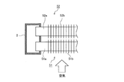
- FIG. 2 is a perspective view of the heat exchanger 50 according to the first embodiment.
- FIG. 3 is a plan view around the distributor 1 according to the first embodiment.
- FIG. 4 is a plan view around the column passing header 2 according to the first embodiment.
- the heat exchanger 50 includes a first heat transfer unit 51 disposed on the upstream side of the circulating air and a second heat transfer unit 52 disposed on the downstream side of the circulating air. It is configured.
- the distributor 1 is disposed on one end side of the first heat transfer section 51, and the column passing header 2 is disposed on the other end side.
- the gas header 3 is arrange
- the distributor 1 has a connecting pipe 1a to which the refrigerant pipe of the refrigeration cycle apparatus 100 is connected.
- the gas header 3 has a hollow structure and has a connection pipe 3a to which the refrigerant pipe of the refrigeration cycle apparatus 100 is connected.
- the row header 2 has a hollow structure, and the heat transfer tubes of the first heat transfer unit 51 and the second heat transfer unit 52 are connected to each other.
- the first heat transfer unit 51 includes a plurality of first heat transfer tubes 51 a that connect the distributor 1 and the row header 2. Moreover, it has the some fin 51b orthogonal to the axial direction of this 1st heat exchanger tube 51a.
- the first heat transfer tubes 51a and the fins 51b are made of, for example, aluminum and are integrated with each other by brazing.
- the second heat transfer section 52 has a plurality of second heat transfer tubes 52 a that connect the gas header 3 and the row header 2. Moreover, it has the some fin 52b orthogonal to the axial direction of this 2nd heat exchanger tube 52a.
- the second heat transfer tubes 52a and the fins 52b are made of, for example, aluminum and are integrated with each other by brazing.
- As the first heat transfer tube 51a and the second heat transfer tube 52a for example, a flat multi-hole tube can be adopted.
- the distributor 1 and the first heat transfer pipe 51a of the first heat transfer section 51 are connected via a connection pipe 51c and a joint 51d. That is, the same number of connection pipes 51 c and joints 51 d are connected to the plurality of first heat transfer pipes 51 a and communicate with the distributor 1. Further, as shown in FIG. 4, a first heat transfer tube 51 a of the first heat transfer unit 51 and a second heat transfer tube 52 a of the second heat transfer unit 52 are connected to the row header 2. At this time, the end portions of the first heat transfer tube 51 a and the second heat transfer tube 52 a are in a state of protruding into the row header 2.
- ⁇ Flow of refrigerant in heat exchanger 50> A configuration in which the heat exchanger 50 according to Embodiment 1 is applied to the outdoor heat exchanger 113 will be described.
- the gas-liquid two-phase refrigerant decompressed by the expansion valve 114 first flows into the connecting pipe 1a of the distributor 1.
- the refrigerant that has flowed into the distributor 1 is branched by a branch passage that will be described later, and flows into the plurality of connection pipes 51c.
- the refrigerant that has flowed into the connection pipe 51c flows into the first heat transfer pipe 51a of the first heat transfer section 51 through the joint 51d.
- the gas-liquid two-phase refrigerant whose degree of dryness has increased by exchanging heat with air flows into the row header 2.
- the refrigerant turned back at the row header 2 flows into the second heat transfer pipe 52 a of the second heat transfer section 52.
- the refrigerant gasified by exchanging heat with air again flows into the gas header 3 and is sucked into the compressor 111 of the refrigeration cycle apparatus 100 from the connection pipe 3a.
- the outdoor heat exchanger 113 functions as a condenser, and the refrigerant flow in the heat exchanger 50 is opposite to that during the heating operation.
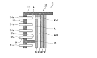
- FIG. 5 is an exploded perspective view of the distributor 1 according to the first embodiment.
- the distributor 1 has a housing 10 as shown in FIG.
- the housing 10 is made of, for example, aluminum.
- the housing 10 is, for example, a rectangular parallelepiped housing.
- the housing 10 is formed of a bottom surface portion 11 (corresponding to the surface portion of the present invention) that faces one side of the opening surface, four side surface portions 12, and a bent portion 13 that can be bent. Yes.
- the surface of the housing 10 is subjected to anticorrosion treatment (such as anticorrosion coating).
- the through hole 14 is a long opening that matches the arrangement of the first heat transfer tubes 51a, and is formed so that the long sides thereof are parallel to each other.
- the bent portion 13 protrudes in a comb shape on the opening surface side of the housing 10.
- a plurality of the bent portions 13 are formed at equal intervals.
- the partition plate 15 in which a plurality of partition plates 15 are erected on the bottom surface portion 11 may be formed integrally with the housing 10 or may be configured separately from the housing 10.
- a plurality of plate-like bodies 20 are stacked and stored in the housing 10.
- the plurality of plate-like bodies 20 have a substantially rectangular shape with the same planar outer dimensions.
- the plate-like body 20 is made of, for example, aluminum.
- the bent portion 13 is bent inside the housing 10, and the plurality of plate-like bodies 20 are caulked and fixed in the housing 10 to be in close contact with each other.
- the plate-like body 20 is placed on the partition plate 15 erected from the bottom surface portion 11 of the housing 10, and a gap A is formed between the bottom surface portion 11 and the plate-like body 20.
- the plate-like bodies 20 may be integrated in advance by brazing.
- the housing 10 and the plate-like body 20 may be fixed by brazing.
- the plurality of plate-like bodies 20 form a branch channel by being laminated.
- the plurality of plate-like bodies 20 are formed by branching out several kinds of flow paths and opening holes by pressing.
- the branch flow path functions as a refrigerant distributor, for example.
- the number of the plate-like bodies 20 can be changed according to the number of branch passages and the length of the passage.
- the plate-like body 20 includes a first plate-like body 21, a second plate-like body 22, a third plate-like body 23, and a fourth plate that have the same rectangular shape in plan view. And a body 24 (corresponding to the second plate body of the present invention).
- a branch channel formed in a laminated state is formed as a through portion.
- the branch channel is a first channel 21 ⁇ / b> A (corresponding to a first opening of the present invention) that is a circular through hole opened in the first plate 21, and a circular penetration opened in the second plate 22.
- Second flow path 22A that is a hole
- first branch flow path 23A that is an S-shaped or substantially Z-shaped through groove opened in the third plate-like body 23, second branch flow path 23B, and a fourth plate shape
- It is constituted by a third flow path 24A (corresponding to the second opening of the present invention) which is a circular through hole opened in the body 24.
- a connecting pipe 1 a is attached to the first flow path 21 ⁇ / b> A of the first plate-like body 21.
- the first flow path 21 ⁇ / b> A communicates with the second flow path 22 ⁇ / b> A of the second plate-like body 22 in a state where the plurality of plate-like bodies 20 are stacked.
- the second flow path 22A is an abbreviation of the first branch flow path 23A, which is an S-shaped or substantially Z-shaped through groove formed in the third plate-shaped body 23 in a state where the plurality of plate-shaped bodies 20 are stacked. It communicates with the central part.
- Both ends of the first branch flow path 23A of the third plate-like body 23 are substantially the center of the second branch flow path 23B, which is an S-shaped or substantially Z-shaped through groove formed in the third plate-like body 23. Communicate with the part. Both ends of the second branch flow path 23B communicate with the third flow path 24A of the fourth plate-like body 24 in a state where the plurality of plate-like bodies 20 are stacked.
- the third flow path 24 ⁇ / b> A communicates with a gap portion A formed between the fourth plate-like body 24 and the bottom surface portion 11 of the housing 10. For example, in the example shown in FIG. 5, four gaps A are formed by the three partition plates 15.
- the partition plate 15 may be formed on the fourth plate-like body 24.
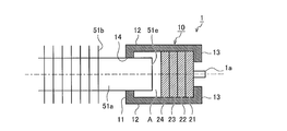
- FIG. 6 is a longitudinal sectional view of the distributor 1 according to the first embodiment.
- FIG. 7 is a cross-sectional view orthogonal to the longitudinal direction of the distributor 1 according to the first embodiment.
- the distributor 1 shown in FIGS. 6 and 7 is an example in which the connection pipe 51 c and the joint 51 d shown in FIG. 3 are omitted, and the first heat transfer pipe 51 a is directly connected to the housing 10.
- the third flow path 24 ⁇ / b> A of the fourth plate-like body 24 communicates with the gap portion A formed between the fourth plate-like body 24 and the bottom surface portion 11 of the housing 10. Yes.
- the tip end portion 51 e of the first heat transfer tube 51 a is disposed through the through hole 14 formed in the bottom surface portion 11 of the housing 10.
- tip part of the connection piping 51c is arrange
- the flow of the refrigerant in the branch flow path of the distributor 1 will be described.
- the heat exchanger 50 functions as an evaporator
- the gas-liquid two-phase flow refrigerant flows from the first flow path 21 ⁇ / b> A of the first plate-like body 21 into the branch flow path.
- the inflowing refrigerant travels straight in the first flow path 21A and the second flow path 22A, collides with the surface of the fourth plate-like body 24 in the first branch flow path 23A of the third plate-like body 23, and becomes S-shaped.
- the flow is diverted in two directions within the substantially Z-shaped first branch flow path 23A.
- the refrigerant having advanced to both ends of the first branch flow path 23A flows into the second branch flow path 23B, and branches in two directions within the S-shaped or substantially Z-shaped second branch flow path 23B.
- the refrigerant that has advanced to both ends of the second branch flow path 23B flows into the pair of third flow paths 24A.
- the refrigerant that has flowed into the third flow path 24A is ejected into the gap A.
- the refrigerant staying in the gap A is uniformly distributed to the first heat transfer tubes 51a and flows in.
- count of a branch and the number of branches are not limited to this example.
- step 1 a plurality of plate-like bodies 20 are stored inside the housing 10 in a stacked state. At this time, the plurality of plate-like bodies 20 may be integrated in advance by brazing or the like.
- step 2 the bent portion 13 of the housing 10 is bent toward the inside of the housing 10, and the plurality of plate-like bodies 20 are fixed in the housing 10.
- step 3 the tip 51 e of the first heat transfer tube 51 a of the heat exchanger 50 is inserted into the through hole 14 of the housing 10 and temporarily assembled.
- Step 4 the heat exchanger 50 and the distributor 1 are put in a furnace and heated in the temporarily assembled state of Step 3, and the housing 10 and the plurality of plate-like bodies 20, and the housing 10 and the first heat transfer tube 51a are connected. Braze in the furnace.
- the first transfer of the heat exchanger 50 is performed via the gaps A formed between the plurality of plate-like bodies 20 having the branch flow paths and the housing 10.
- the refrigerant stored in the gap A is homogenized and flows equally into each first heat transfer pipe 51a. Therefore, it is possible to suppress the liquid refrigerant and the gas refrigerant from flowing into each heat transfer tube in a state of drifting, and to maximize the heat transfer performance of the heat exchanger 50.
- Embodiment 2 FIG. In the distributor 1 according to the first embodiment, the third flow path 24A of the fourth plate-like body 24 is opened in the gap A, but in the second embodiment, the third flow path 24A is arranged. There are differences. Moreover, there is a difference in the protruding dimension of the first heat transfer tube 51a. Therefore, the configuration around the gap A will be described. Since the other configuration is the same as that of the distributor 1 according to the first embodiment, the same reference numerals are given to the drawings, and description thereof is omitted.
- FIG. 8 is a longitudinal sectional view of the distributor 1 according to the second embodiment.
- the distributor 1 according to the second embodiment includes a third flow path 24 ⁇ / b> A for the first heat transfer tube 51 a located at the bottom of the plurality of first heat transfer tubes 51 a protruding into the gap A.
- the position of is defined. That is, among the plurality of first heat transfer tubes 51a, the lower end K2 of the third flow path 24A is disposed at the same or lower position in the horizontal direction with respect to the lower end K1 of the first heat transfer tube 51a located at the lowermost portion. Yes.
- the projecting dimension Z of the first heat transfer tube 51 a in the gap A is defined by the distance between the distal end portion 51 e of the first heat transfer tube 51 a and the inner surface of the bottom surface portion 11 of the housing 10.
- the protruding dimension Z according to the second embodiment is defined in a range of 3 mm or more and 10 mm or less.
- the position of the third flow path 24A as described above, the liquid refrigerant Is immediately discharged from the gap A.
- the amount of necessary refrigerant in the refrigeration cycle apparatus 100 can be suppressed.
- gap part A is prescribed
- Embodiment 3 FIG.
- the third flow path 24A of the fourth plate-like body 24 is open in the gap A, but in the third embodiment, the third flow path 24A is arranged. There are differences. Therefore, the configuration around the gap A will be described. Since the other configuration is the same as that of the distributor 1 according to the first embodiment, the same reference numerals are given to the drawings, and description thereof is omitted.
- FIG. 9 is a longitudinal sectional view of the distributor 1 according to the third embodiment.
- FIG. 10 is a perspective view of a plate-like body of the distributor 1 according to the third embodiment.
- the distributor 1 according to the third embodiment is formed with a plurality of third flow paths 24 ⁇ / b> A that open to the gap A with respect to one end side of the second branch flow path 23 ⁇ / b> B.
- the plurality of third flow paths 24 ⁇ / b> A are provided in a one-to-one correspondence with the plurality of first heat transfer tubes 51 a or positions facing the through holes 14 of the housing 10. That is, as shown in FIG.
- the plurality of third flow paths 24A have the same height as the plurality of first heat transfer tubes 51a or the through holes 14 (positions that are the same in the longitudinal direction of the distributor 1). The same number as that of the first heat transfer tubes 51a is provided. Also, the plurality of third flow paths 24A are formed side by side at positions communicating with one end side of the second branch flow path 23B formed in the third plate-like body 23 as shown in FIG.
- the third flow path 24A is provided at a position facing the plurality of first heat transfer tubes 51a. For this reason, the refrigerant that has flowed out of the third flow paths 24A is distributed to the first heat transfer tubes 51a facing each other smoothly and evenly. Therefore, it is possible to suppress the refrigerant from flowing into each heat transfer tube in a state of drifting and to maximize the heat transfer performance of the heat exchanger 50.
- Embodiment 4 FIG.
- the distributor 1 according to the first embodiment an example in which the first branch flow path 23A and the second branch flow path 23B are formed in one third plate-like body 23 is shown, but in the fourth embodiment, The configurations of the first branch channel 23A and the second branch channel 23B are different from those of the first embodiment. Since other configurations are the same as those of the distributor 1 according to the first embodiment, the same reference numerals are given to the drawings, and description thereof is omitted.
- FIG. 11 is an exploded perspective view of the distributor 1 according to the fourth embodiment.
- the plate-like body 30 includes a first plate-like body 31, a second plate-like body 32, a third plate-like body 33, and a fourth plate that have the same rectangular shape in plan view.
- the plate-shaped body 34, the 5th plate-shaped body 35, and the 6th plate-shaped body 36 are comprised.
- a branch channel formed in a stacked state is formed as a through portion.
- the branch flow path is a first flow path 31A (corresponding to the first opening of the present invention) which is a circular through hole opened in the first plate-like body 31, and a circular penetration opened in the second plate-like body 32.
- the second flow path 32A that is a hole, the first branch flow path 33A that is an S-shaped or substantially Z-shaped through groove opened in the third plate 33, and the circular through hole that is opened in the fourth plate 34 Are two third flow paths 34A, two second branch flow paths 35A, which are S-shaped or substantially Z-shaped through-grooves opened in the fifth plate-like body 35, and a circular shape opened in the sixth plate-like body 36.
- a connecting pipe 1 a is attached to the first flow path 31 ⁇ / b> A of the first plate-like body 31.
- the first flow path 31A communicates with the second flow path 22A of the second plate-like body 32 in a state where the plurality of plate-like bodies 30 are stacked.
- the second flow path 32A is an abbreviation of the first branch flow path 33A, which is an S-shaped or substantially Z-shaped through groove formed in the third plate-shaped body 33 in a state where the plurality of plate-shaped bodies 30 are stacked. It communicates with the central part.
- Both end portions of the first branch flow path 33A communicate with the third flow path 34A of the fourth plate-shaped body 34 in a state where the plurality of plate-shaped bodies 30 are stacked.
- the third flow path 34A is an abbreviation of the second branch flow path 35A that is an S-shaped or substantially Z-shaped through groove formed in the fifth plate-shaped body 35 in a state where the plurality of plate-shaped bodies 30 are stacked. It communicates with the central part. Both ends of the second branch flow path 35A communicate with the fourth flow path 36A of the sixth plate-like body 36 in a state where the plurality of plate-like bodies 30 are stacked.
- the fourth flow path 36 ⁇ / b> A communicates with a gap portion A formed between the sixth plate-like body 36 and the bottom surface portion 11 of the housing 10. For example, in the example of FIG. 11, four gaps A are formed by three partition plates 15.
- the flow of the refrigerant in the branch flow path of the distributor 1 will be described.
- the heat exchanger 50 functions as an evaporator
- the gas-liquid two-phase flow refrigerant flows from the first flow path 31 ⁇ / b> A of the first plate 31 into the branch flow path.
- the inflowing refrigerant travels straight in the first flow path 31A and the second flow path 32A, collides with the surface of the fourth plate-shaped body 34 in the first branch flow path 33A of the third plate-shaped body 33, and is S-shaped.
- the flow is diverted in two directions in the first branch flow path 33A having a substantially Z shape.
- the refrigerant that has advanced to both ends of the first branch flow path 33A is It flows into the two third flow paths 34 ⁇ / b> A of the fourth plate 34.
- the refrigerant flowing into the third flow path 34A collides with the surface of the sixth plate-shaped body 36 in the second branched flow path 35A of the fifth plate-shaped body 35, and the second branched flow having an S shape or a substantially Z shape.
- the current is diverted in two directions in the path 35A.
- the refrigerant that has advanced to both ends of the second branch flow path 35A flows into the four fourth flow paths 36A of the sixth plate-like body 36, respectively.
- the refrigerant that has flowed into the fourth flow path 36A is ejected into the gap A.
- the refrigerant staying in the gap A is uniformly distributed to the first heat transfer tubes 51a and flows in.
- distributor 1 which passed through the 2 times branch flow path and was made into 4 branches was shown in the branch flow path concerning Embodiment 4, the frequency
- the branch channel may be 16 branches, and the refrigerant may be branched so as to have a one-to-one relationship with the first heat transfer tube 51a.
- the first branch flow path 33A and the second branch flow path 35A are formed in different plate-like bodies 30.
- the refrigerant is less affected by gravity and can be more evenly branched. Therefore, it is possible to suppress the refrigerant from flowing into each heat transfer tube in a state of drifting and to maximize the heat transfer performance of the heat exchanger 50.
- the distributor 1 includes: (1) A housing 10 having a bottom surface portion 11 and a through-hole 14 opening in the bottom surface portion 11, and a plurality of plate-like bodies 20 and 30 stacked in the housing 10, and a plurality of plate-like shapes
- the bodies 20 and 30 are arranged on one end side of the plurality of plate-like bodies, and are arranged on the other end side of the first plate-like bodies 21 and 3 having the first opening and the plurality of plate-like bodies,
- a second plate-like body having a plurality of second openings, a branch flow path connecting the first openings and the plurality of second openings, and the housing 10 in a state of passing through the through holes 14.
- a plurality of connection pipes 51c attached to the bottom surface portion 11, and between the bottom surface portion 11 and the second plate-like body, a partition plate 15 that contacts the bottom surface portion 11 and the second plate-like body. are arranged.
- the partition plate 15 is formed on the bottom surface portion 11.
- the partition plate 15 is formed in the 2nd plate-shaped body.
- the refrigerant stored in the gap portion A formed by the partition plate 15 is homogenized and then uniformly flows into the heat transfer tubes. Therefore, the liquid refrigerant and the gas refrigerant are prevented from flowing into each heat transfer tube in a drifted state, and the heat transfer performance of the heat exchanger 50 can be maximized. Further, by housing the plurality of plate-like bodies 20 and 30 in the housing 10, the corrosion of the plate-like bodies 20 and 30 can be suppressed and the refrigerant can be prevented from leaking from the branch flow path.
- a gap A defined by the partition plate 15 is formed between the bottom surface 11 and the second plate-like body.
- the lower end K2 of the second opening that opens in one gap A is the same position in the horizontal direction as the lower end K1 of the lowermost connection pipe 51c among the plurality of connection pipes 51c arranged in one gap A, Or it is located below lower end K1 of connection piping 51c located in the lowest part among a plurality of connection piping 51c. According to such a distributor 1, the liquid refrigerant stored in the space A can be suppressed to the minimum.
- the condensed liquid refrigerant accumulates in the lower portion of the gap A, but the position of the second opening (third flow path 24A) is configured as described above. As a result, the liquid refrigerant is immediately discharged from the gap A. For this reason, the amount of necessary refrigerant in the refrigeration cycle apparatus 100 can be suppressed.
- the plurality of second openings are provided as a pair with respect to the plurality of connection pipes 51c and are formed at positions facing each other. It is a thing.
- a gap portion A partitioned by the partition plate 15 is formed between the bottom surface portion 11 and the second plate-like body, and one gap portion A is formed.
- a plurality of second openings are opened.
- each 2nd opening part is provided in the position facing the some 1st heat exchanger tube 51a. For this reason, the refrigerant that has flowed out of each second opening is distributed to each connection pipe 51c (first heat transfer pipe 51a) facing smoothly and evenly. Therefore, it is possible to suppress the refrigerant from flowing into each connection pipe 51c (first heat transfer pipe 51a) in a state of drifting, and to maximize the heat transfer performance of the heat exchanger 50.
- the distance between the inner surface of the bottom surface portion 11 and the tips of the plurality of connection pipes 51c penetrating the through hole 14 is 3 mm or more and 10 mm or less. It is a dimension. According to such a distributor 1, when the housing 10 and the first heat transfer tube 51a are brazed, it is possible to prevent the wax from flowing into the flow path of the first heat transfer tube 51a. Furthermore, since the first heat transfer tube 51a protrudes into the gap A, the volume of the gap A can be reduced, and the necessary refrigerant amount in the refrigeration cycle apparatus 100 can be suppressed.
- the plurality of connection pipes 51c are configured as heat transfer tubes.
- a heat exchanger tube is comprised as a flat multi-hole tube. According to such a distributor 1, the heat exchanger 50 can be made compact by connecting the heat transfer tubes (first heat transfer tubes 51 a) directly to the housing 10.
- the plurality of plate-like bodies 20 and 30 are fixed to each other via a brazing material.
- the housing 10 and the plate-like body in which the first opening is formed are fixed via a brazing material. According to such a distributor 1, it is possible to reliably prevent the refrigerant from leaking.
- the first heat transfer pipe 51a of the first heat transfer section 51 and the second heat transfer pipe 52a of the second heat transfer section 52 are connected to each other via the hollow header 2. It is an exchanger. According to such a heat exchanger 50, the heat exchanger 50 can be compactly configured by connecting the heat transfer tubes directly to the column header 2.
Abstract
Description
また、ハウジング内に複数の板状体を収納することで、板状体の腐食を抑制して、冷媒が分岐流路から漏洩することを防止することができる。 In the distributor according to the present invention, a gap is formed between the surface portion in the housing and the second plate-like body by the partition plate, and each connection pipe ( Evenly flows into the heat transfer tubes). Therefore, it is possible to suppress the liquid refrigerant and the gas refrigerant from flowing into each connection pipe (heat transfer pipe) in a state of drifting, and to maximize the heat transfer performance of the heat exchanger.
Moreover, by accommodating a plurality of plate-like bodies in the housing, corrosion of the plate-like bodies can be suppressed and the refrigerant can be prevented from leaking from the branch flow path.
なお、以下で説明する構成、動作等は、一例にすぎず、本発明に係る分配器、熱交換器、及び、空気調和装置は、そのような構成、動作等である場合に限定されない。また、各図において、同一又は類似するものには、同一の符号を付すか、又は、符号を付すことを省略している。また、細かい構造については、適宜図示を簡略化又は省略している。また、重複又は類似する説明については、適宜簡略化又は省略している。 Hereinafter, a distributor (laminated header), a heat exchanger, and an air conditioner according to the present invention will be described with reference to the drawings.
In addition, the structure, operation | movement, etc. which are demonstrated below are only examples, and the divider | distributor, heat exchanger, and air conditioning apparatus which concern on this invention are not limited to such a structure, operation | movement, etc. Moreover, in each figure, the same code | symbol is attached | subjected to the same or similar thing, or attaching | subjecting code | symbol is abbreviate | omitted. Further, the illustration of the fine structure is simplified or omitted as appropriate. In addition, overlapping or similar descriptions are appropriately simplified or omitted.
実施の形態1に係る分配器、熱交換器、及び、冷凍サイクル装置について説明する。
<冷凍サイクル装置100の構成>
図1は、実施の形態1に係る冷凍サイクル装置100の構成図である。
冷凍サイクル装置100は、室外ユニット110と室内ユニット120とを備えている。室外ユニット110と室内ユニット120は、液側連絡配管101およびガス側連絡配管102を介して互いに接続されている。冷凍サイクル装置100では、室外ユニット110と、室内ユニット120と、液側連絡配管101と、ガス側連絡配管102とによって、冷媒回路が形成されている。
A distributor, a heat exchanger, and a refrigeration cycle apparatus according to
<Configuration of
FIG. 1 is a configuration diagram of a
The
次に、冷凍サイクル装置100の運転動作について説明する。冷凍サイクル装置100は、四方切替弁112の流路を切り替えることで冷房運転と暖房運転とを実現可能である。
暖房運転中の冷媒回路では、四方切替弁112を図1に示した実線に流路に切り替えた状態で冷凍サイクルを形成する。暖房運転の場合、圧縮機111により高温高圧状態となって送出された冷媒は、四方切替弁112、室内熱交換器121の順に流れ、室内熱交換器121で室内送風機122から送出された空気を加熱し凝縮する。その後、膨張弁114で減圧され、室外熱交換器113へ流入する。室外熱交換器113内を通過する冷媒は室外送風機115から送出された空気により加熱され蒸発する。そして、四方切替弁112を通って圧縮機111の吸入口へ流入する。
一方冷房運転は、四方切替弁112を図1に示す破線に流路を切り替えて運転する。このとき、冷媒は暖房運転とは逆方向に流れ、室外熱交換器113が凝縮器として作用し、室内熱交換器121は蒸発器として機能する。 <Operation of the
Next, the operation of the
In the refrigerant circuit during the heating operation, the refrigeration cycle is formed in a state where the four-
On the other hand, in the cooling operation, the four-
図2は、実施の形態1に係る熱交換器50の斜視図である。
図3は、実施の形態1に係る分配器1周りの平面図である。
図4は、実施の形態1に係る列渡しヘッダ2周りの平面図である。
図2に示すように、熱交換器50は、流通する空気の上流側に配置された第1伝熱部51と、流通する空気の下流側に配置された第2伝熱部52と、により構成されている。第1伝熱部51の一端側には分配器1が配置され、他端側には列渡しヘッダ2が配置されている。
また、第2伝熱部52の一端側には、ガスヘッダ3が配置され、他端側には列渡しヘッダ2が配置されている。分配器1は、冷凍サイクル装置100の冷媒配管が接続される接続管1aを有している。
ガスヘッダ3は、中空構造とされ、同じく冷凍サイクル装置100の冷媒配管が接続される接続管3aを有している。
列渡しヘッダ2は、中空構造とされ、第1伝熱部51と第2伝熱部52の各伝熱管が接続されている。 <Configuration of
FIG. 2 is a perspective view of the
FIG. 3 is a plan view around the
FIG. 4 is a plan view around the
As shown in FIG. 2, the
Moreover, the
The
The
第1伝熱管51aとフィン51bとは、例えばアルミニウム製とし、互いにろう付けにて一体化されている。
第2伝熱部52は、ガスヘッダ3と列渡しヘッダ2とを接続する複数の第2伝熱管52aを有している。また、この第2伝熱管52aの軸方向に対して直交する複数のフィン52bを有している。
第2伝熱管52aとフィン52bとは、例えばアルミニウム製とし、互いにろう付けにて一体化されている。
第1伝熱管51aと第2伝熱管52aとは、例えば扁平多穴管を採用することができる。 The first
The first
The second
The second
As the first
また、列渡しヘッダ2には、図4に示すように第1伝熱部51の第1伝熱管51aと、第2伝熱部52の第2伝熱管52aとが接続されている。このとき、第1伝熱管51aと、第2伝熱管52aの端部は、列渡しヘッダ2の内部に突出した状態となっている。 As shown in FIG. 3, the
Further, as shown in FIG. 4, a first
室外熱交換器113に実施の形態1に係る熱交換器50を適用した構成を説明する。
膨張弁114で減圧された気液二相冷媒が、まず、分配器1の接続管1aに流入する。分配器1内に流入した冷媒は、後述する分岐流路で分岐し、複数の接続配管51cに流入する。接続配管51cに流入した冷媒は、ジョイント51dを介して第1伝熱部51の第1伝熱管51aに流入する。空気と熱交換して乾き度が増した気液二相冷媒は、列渡しヘッダ2内に流入する。列渡しヘッダ2で折り返した冷媒は、第2伝熱部52の第2伝熱管52aに流入する。再び空気と熱交換してガス化した冷媒は、ガスヘッダ3に流入し、接続管3aから冷凍サイクル装置100の圧縮機111に吸引される。
なお、冷凍サイクル装置100が冷房運転中には、室外熱交換器113が凝縮器として機能し、熱交換器50内での冷媒の流れは暖房運転時と逆向きとなる。 <Flow of refrigerant in
A configuration in which the
The gas-liquid two-phase refrigerant decompressed by the
During the cooling operation of the
図5は、実施の形態1に係る分配器1の分解斜視図である。
分配器1は、図5に示すように、ハウジング10を有している。ハウジング10は、例えばアルミニウム製である。ハウジング10は、例えば直方体の筐体である。ハウジング10は、一面が開口し、この開口面に対向する底面部11(本発明の面部に相当する)と、4面の側面部12と、曲折が可能な曲折部13と、で構成されている。ハウジング10の表面には防食処理(防食塗装等)が施されている。 <Configuration of
FIG. 5 is an exploded perspective view of the
The
板状体20の構成枚数は、分岐流路の分岐回数や流路長さに応じて変更することが可能である。 The plurality of plate-
The number of the plate-
以下に、実施の形態1に係る板状体20の構成について説明する。
板状体20は、例えば図5に示すように、平面視で同一の長方形形状となる第1板状体21と、第2板状体22と、第3板状体23と、第4板状体24(本発明の第2板状体に相当する)と、により構成されている。 <Configuration of plate-
Below, the structure of the plate-shaped
For example, as shown in FIG. 5, the plate-
この第1流路21Aは、複数の板状体20が積層された状態で、第2板状体22の第2流路22Aと連通する。
第2流路22Aは、複数の板状体20が積層された状態で、第3板状体23に形成されたS字もしくは略Z字形状の貫通溝である第1分岐流路23Aの略中央部分に連通する。 A connecting
The
The
第2分岐流路23Bの両端部は、複数の板状体20が積層された状態で、第4板状体24の第3流路24Aに連通する。
そして、第3流路24Aは、第4板状体24とハウジング10の底面部11との間に形成された空隙部Aに連通している。
空隙部Aは仕切板15に仕切られており、例えば図5の例では、3枚の仕切板15により4つの空隙部Aが形成される。 Both ends of the first
Both ends of the second
The
For example, in the example shown in FIG. 5, four gaps A are formed by the three
ここで、図6、7を用いて空隙部Aの構成を説明する。
図6は、実施の形態1に係る分配器1の長手方向の断面図である。
図7は、実施の形態1に係る分配器1の長手方向に直交する断面図である。
図6、7に記載の分配器1は、図3に示した接続配管51cとジョイント51dとを省略し、ハウジング10に直接、第1伝熱管51aを接続した例である。
図6、7に示すように、第4板状体24の第3流路24Aは、第4板状体24とハウジング10の底面部11との間に形成された空隙部Aに連通している。また、空隙部A内には、第1伝熱管51aの先端部51eがハウジング10の底面部11に形成された貫通孔14を貫通して配置されている。なお、図3に示したように接続配管51cとジョイント51dとを介して分配器1と第1伝熱管51aとを接続する場合には、接続配管51cの先端部が空隙部A内に配置される。 <Configuration around the gap A of the
Here, the configuration of the gap A will be described with reference to FIGS.
FIG. 6 is a longitudinal sectional view of the
FIG. 7 is a cross-sectional view orthogonal to the longitudinal direction of the
The
As shown in FIGS. 6 and 7, the
次に、分配器1の分岐流路内の冷媒の流れについて説明する。
以下、熱交換器50が蒸発器として機能する場合を例に説明する。
はじめに、気液二相流の冷媒が、第1板状体21の第1流路21Aから分岐流路内に流入する。流入した冷媒は、第1流路21A、第2流路22A内を直進し、第3板状体23の第1分岐流路23A内で第4板状体24の表面に衝突し、S字もしくは略Z字形状の第1分岐流路23A内で2方向に分流する。第1分岐流路23Aの両端まで進んだ冷媒は、第2分岐流路23Bに流入し、S字もしくは略Z字形状の第2分岐流路23B内で2方向に分岐する。第2分岐流路23Bの両端まで進んだ冷媒は、一対の第3流路24A内に流入する。 <Flow of refrigerant in branch flow path>
Next, the flow of the refrigerant in the branch flow path of the
Hereinafter, a case where the
First, the gas-liquid two-phase flow refrigerant flows from the
なお、実施の形態1に係る分岐流路では、2回分岐流路を通り、4分岐とした分配器1の例を示したが、分岐の回数や分岐数はこの例に限定されない。 The refrigerant that has flowed into the
In addition, although the example of the divider |
次に、分配器1の組み立て工程について説明する。
ステップ1として、ハウジング10の内部に複数の板状体20を積層した状態で収納する。このとき複数の板状体20同士が予めろう付け等で一体化されていてもよい。
ステップ2として、ハウジング10の曲折部13をハウジング10の内部側に曲折し、複数の板状体20をハウジング10内に固定する。
次に、ステップ3として、熱交換器50の第1伝熱管51aの先端部51eをハウジング10の貫通孔14に挿通し仮組する。
ステップ4として、ステップ3の仮組状態で熱交換器50、及び、分配器1を炉に入れて加熱し、ハウジング10と複数の板状体20、及び、ハウジング10と第1伝熱管51aを炉中でろう付けする。 <Assembly process of
Next, the assembly process of the
As
As
Next, as
As
実施の形態1に係る分配器1によれば、分岐流路を有する複数の板状体20と、ハウジング10との間に形成された空隙部Aを介して、熱交換器50の第1伝熱管51aに冷媒を流入させるため、空隙部A内に貯留された冷媒が均質化され、各第1伝熱管51aに均等に流入する。よって、各伝熱管へ液冷媒とガス冷媒とが偏流した状態で流入することを抑制し、熱交換器50の伝熱性能を最大限引き出すことが可能となる。
また、表面に防食処理を行ったハウジング10内に複数の板状体20を収納することで、板状体20の腐食を抑制して、冷媒が分岐流路から漏洩することを防止することができる。 <Effect>
According to the
In addition, by housing a plurality of plate-
実施の形態1に係る分配器1では、空隙部Aに第4板状体24の第3流路24Aが開口している構成としたが、実施の形態2では第3流路24Aの配置に相違点がある。また、第1伝熱管51aの突出寸法に相違点がある。
このため、空隙部A周りの構成について説明する。その他の構成は実施の形態1に係る分配器1と同様なため、図面に同一符号を付し、説明を省略する。
In the
Therefore, the configuration around the gap A will be described. Since the other configuration is the same as that of the
図8は、実施の形態2に係る分配器1の長手方向の断面図である。
実施の形態2に係る分配器1は、図8に示すように空隙部A内に突出する複数の第1伝熱管51aのうち、最下部に位置する第1伝熱管51aに対する第3流路24Aの位置が規定されている。すなわち、複数の第1伝熱管51aのうち、最下部に位置する第1伝熱管51aの下端K1に対して、水平方向で第3流路24Aの下端K2が同一もしくは低くなる位置に配置されている。
また、空隙部A内における第1伝熱管51aの突出寸法Zは、第1伝熱管51aの先端部51eとハウジング10の底面部11の内面との距離で規定される。実施の形態2に係る突出寸法Zは、3mm以上10mm以下の範囲に規定される。 <Configuration of
FIG. 8 is a longitudinal sectional view of the
As shown in FIG. 8, the
Further, the projecting dimension Z of the first
実施の形態2に係る分配器1によれば、複数の第1伝熱管51aのうち、最下部に位置する第1伝熱管51aの下端K1に対して、水平方向で第3流路24Aの下端K2が同一もしくは低くなる位置に配置されているため、空隙部A内に貯留される液冷媒を最小限に抑制することができる。すなわち、特に熱交換器50が凝縮器として機能する場合に、凝縮した液冷媒が空隙部Aの下部に溜まるが、第3流路24Aの位置を上記のような構成にすることで、液冷媒が空隙部Aから直ちに排出される。このため、冷凍サイクル装置100内の必要冷媒量を抑制することができる。
また、空隙部A内における第1伝熱管51aの突出寸法Zを3mm以上10mm以下の範囲に規定することで、ハウジング10と第1伝熱管51aとをろう付けした際に、第1伝熱管51aの流路内にろうが流入することを防止することができる。さらに、空隙部A内に第1伝熱管51aが突出することで、空隙部Aの容積が減少し、冷凍サイクル装置100内の必要冷媒量を抑制することができる。 <Effect>
According to the
Moreover, when the projection dimension Z of the 1st
実施の形態1に係る分配器1では、空隙部Aに第4板状体24の第3流路24Aが開口している構成としたが、実施の形態3では第3流路24Aの配置に相違点がある。
このため、空隙部A周りの構成について説明する。その他の構成は実施の形態1に係る分配器1と同様なため、図面に同一符号を付し、説明を省略する。
In the
Therefore, the configuration around the gap A will be described. Since the other configuration is the same as that of the
図9は、実施の形態3に係る分配器1の長手方向の断面図である。
図10は、実施の形態3に係る分配器1の板状体の斜視図である。
実施の形態3に係る分配器1は、図9、10に示すように空隙部Aに開口する第3流路24Aが第2分岐流路23Bの一端側に対して複数箇所形成されている。この複数の第3流路24Aは、複数の第1伝熱管51a、または、ハウジング10の貫通孔14に対向する位置に1対1で対応して設けられている。すなわち、図9に示すように、複数の第3流路24Aは、複数の第1伝熱管51a、または、貫通孔14と同一となる高さ(分配器1の長手方向で同一となる位置)に第1伝熱管51aと同一の個数となるように設けられている。また、複数の第3流路24Aは、図10に示すように第3板状体23に形成された第2分岐流路23Bの一端側に連通する位置に並んで形成されている。 <Configuration of
FIG. 9 is a longitudinal sectional view of the
FIG. 10 is a perspective view of a plate-like body of the
As shown in FIGS. 9 and 10, the
実施の形態3に係る分配器1によれば、複数の第1伝熱管51aに対向する位置に第3流路24Aが設けられている。このため、各第3流路24Aを流出した冷媒がスムーズかつ均等に対向する各第1伝熱管51aに分配される。よって、各伝熱管へ冷媒が偏流した状態で流入することを抑制し、熱交換器50の伝熱性能を最大限引き出すことが可能となる。 <Effect>
According to the
実施の形態1に係る分配器1では、第1分岐流路23Aと第2分岐流路23Bとを1枚の第3板状体23に形成した例を示したが、実施の形態4では、第1分岐流路23Aと第2分岐流路23Bの構成が実施の形態1と異なっている。
その他の構成は、実施の形態1に係る分配器1と同様なため、図面に同一符号を付し、説明を省略する。
In the
Since other configurations are the same as those of the
以下に、実施の形態4に係る板状体30の構成について説明する。
図11は、実施の形態4に係る分配器1の分解斜視図である。
板状体30は、例えば図11に示すように、平面視で同一の長方形形状となる第1板状体31と、第2板状体32と、第3板状体33と、第4板状体34と、第5板状体35と、第6板状体36(本発明の第2板状体に相当する)と、により構成されている。 <Configuration of plate-
Below, the structure of the plate-shaped
FIG. 11 is an exploded perspective view of the
For example, as shown in FIG. 11, the plate-
この第1流路31Aは、複数の板状体30が積層された状態で、第2板状体32の第2流路22Aと連通する。
第2流路32Aは、複数の板状体30が積層された状態で、第3板状体33に形成されたS字もしくは略Z字形状の貫通溝である第1分岐流路33Aの略中央部分に連通する。
第1分岐流路33Aの両端部は、複数の板状体30が積層された状態で、第4板状体34の第3流路34Aにそれぞれ連通する。 A connecting
The
The
Both end portions of the first
第2分岐流路35Aの両端部は、複数の板状体30が積層された状態で、第6板状体36の第4流路36Aにそれぞれ連通する。
そして、第4流路36Aは、第6板状体36とハウジング10の底面部11との間に形成された空隙部Aに連通している。
空隙部Aは仕切板15に仕切られており、例えば図11の例では、3枚の仕切板15により4つの空隙部Aが形成される。 The
Both ends of the second
The
For example, in the example of FIG. 11, four gaps A are formed by three
次に、分配器1の分岐流路内の冷媒の流れについて説明する。
以下、熱交換器50が蒸発器として機能する場合を例に説明する。
はじめに、気液二相流の冷媒が、第1板状体31の第1流路31Aから分岐流路内に流入する。流入した冷媒は、第1流路31A、第2流路32A内を直進し、第3板状体33の第1分岐流路33A内で第4板状体34の表面に衝突し、S字もしくは略Z字形状の第1分岐流路33A内で2方向に分流する。第1分岐流路33Aの両端まで進んだ冷媒は、
第4板状体34の2つの第3流路34Aに流入する。
第3流路34Aに流入した冷媒は、第5板状体35の第2分岐流路35A内で第6板状体36の表面に衝突し、S字もしくは略Z字形状の第2分岐流路35A内で2方向に分流する。第2分岐流路35Aの両端まで進んだ冷媒は、第6板状体36の4つの第4流路36Aにそれぞれ流入する。 <Flow of refrigerant in branch flow path>
Next, the flow of the refrigerant in the branch flow path of the
Hereinafter, a case where the
First, the gas-liquid two-phase flow refrigerant flows from the
It flows into the two
The refrigerant flowing into the
なお、実施の形態4に係る分岐流路では、2回分岐流路を通り、4分岐とした分配器1の例を示したが、分岐の回数や分岐数はこの例に限定されない。例えば、分岐流路を16分岐とし、第1伝熱管51aと1対1となるように冷媒を分岐させてもよい。 The refrigerant that has flowed into the
In addition, although the example of the divider |
実施の形態4に係る分配器1によれば、実施の形態1に係る効果に加え、第1分岐流路33Aと第2分岐流路35Aとが異なる板状体30に形成されているため、冷媒が重力の影響を受けにくくなり、より均一に冷媒を分岐することができる。よって、各伝熱管へ冷媒が偏流した状態で流入することを抑制し、熱交換器50の伝熱性能を最大限引き出すことが可能となる。 <Effect>
According to the
実施の形態1~4に係る分配器1は、
(1)底面部11と、底面部11に開口する貫通孔14とを備えたハウジング10と、ハウジング10内に積層された複数の板状体20、30と、を有し、複数の板状体20、30は、複数の板状体のうち一端側に配置され、第1開口部が開口した第1板状体21、3と、複数の板状体のうち他端側に配置され、複数の第2開口部が開口した第2板状体と、を含み、第1開口部と、複数の第2開口部とを接続する分岐流路と、貫通孔14を貫通した状態でハウジング10の底面部11に取り付けられた複数の接続配管51cと、を有し、底面部11と第2板状体との間には、底面部11と第2板状体とに当接する仕切板15が配置されたものである。
(2)また、(1)に記載の分配器1において、仕切板15は、底面部11に形成されたものである。
(3)また、(1)に記載の分配器1において、仕切板15は、第2板状体に形成されたものである。 <Configuration of
The
(1) A
(2) In the
(3) Moreover, in the divider |
また、ハウジング10内に複数の板状体20、30を収納することで、板状体20、30の腐食を抑制して、冷媒が分岐流路から漏洩することを防止することができる。 According to such a
Further, by housing the plurality of plate-
このような分配器1によれば、空隙部A内に貯留される液冷媒を最小限に抑制することができる。すなわち、特に熱交換器50が凝縮器として機能する場合に、凝縮した液冷媒が空隙部Aの下部に溜まるが、第2開口部(第3流路24A)の位置を上記のような構成にすることで、液冷媒が空隙部Aから直ちに排出される。このため、冷凍サイクル装置100内の必要冷媒量を抑制することができる。 (4) Further, in the
According to such a
(6)また、(5)に記載の分配器1において、底面部11と第2板状体との間には、仕切板15で区画された空隙部Aが形成され、1つの空隙部Aには、複数の第2開口部が開口するものである。
このような分配器1によれば、複数の第1伝熱管51aに対向する位置に各第2開口部が設けられる。このため、各第2開口部を流出した冷媒がスムーズかつ均等に対向する各接続配管51c(第1伝熱管51a)に分配される。よって、各接続配管51c(第1伝熱管51a)へ冷媒が偏流した状態で流入することを抑制し、熱交換器50の伝熱性能を最大限引き出すことが可能となる。 (5) Further, in the
(6) Moreover, in the
According to such a
このような分配器1によれば、ハウジング10と第1伝熱管51aとをろう付けした際に、第1伝熱管51aの流路内にろうが流入することを防止することができる。さらに、空隙部A内に第1伝熱管51aが突出することで、空隙部Aの容積が減少し、冷凍サイクル装置100内の必要冷媒量を抑制することができる。 (7) Further, in the
According to such a
(9)また、(8)に記載の分配器1において、伝熱管は、扁平多穴管として構成されたものである。
このような分配器1によれば、伝熱管(第1伝熱管51a)を直接ハウジング10に接続することで、熱交換器50をコンパクトに構成することができる。 (8) In the
(9) Moreover, in the divider |
According to such a
このような分配器1によれば、ハウジング10の内部に収納された板状体20、30の腐食を防止することで、冷媒の漏洩を防ぐことができる。 (10) In the
According to such a
(12)また、(1)~(11)に記載の分配器1において、ハウジング10と、第1開口部が形成された板状体とは、ろう材を介して固定されたものである。
このような分配器1によれば、冷媒の漏洩を確実に防ぐことができる。 (11) Further, in the
(12) In the
According to such a
このような熱交換器50によれば、伝熱管を直接列渡しヘッダ2に接続することで、熱交換器50をコンパクトに構成することができる。 (13) The first
According to such a
このような空気調和装置によれば、熱交換器の伝熱性能が向上するため、成績係数の高い空気調和装置を提供することができる。 (14) Moreover, it is an air conditioning apparatus which has a heat exchanger as described in (13).
According to such an air conditioner, since the heat transfer performance of the heat exchanger is improved, an air conditioner with a high coefficient of performance can be provided.
Claims (14)
- 面部と、該面部に開口する貫通孔とを備えたハウジングと、
前記ハウジング内に積層された複数の板状体と、
を有し、
前記複数の板状体は、
前記複数の板状体のうち一端側に配置され、第1開口部が開口した第1板状体と、
前記複数の板状体のうち他端側に配置され、複数の第2開口部が開口した第2板状体と、を含み、
前記第1開口部と、前記複数の第2開口部とを接続する分岐流路と、
前記貫通孔を貫通した状態で前記ハウジングの面部に取り付けられた複数の接続配管と、
を有し、
前記面部と前記第2板状体との間には、前記面部と前記第2板状体とに当接する仕切板が配置された分配器。 A housing having a surface portion and a through-hole opening in the surface portion;
A plurality of plate-like bodies stacked in the housing;
Have
The plurality of plate-like bodies are:
A first plate-like body disposed on one end side of the plurality of plate-like bodies and having a first opening opened;
A second plate-like body disposed on the other end side of the plurality of plate-like bodies and having a plurality of second openings opened therein,
A branch flow path connecting the first opening and the plurality of second openings;
A plurality of connecting pipes attached to the surface portion of the housing in a state of penetrating the through hole;
Have
The divider | distributor by which the partition plate contact | abutted to the said surface part and the said 2nd plate-shaped body is arrange | positioned between the said surface part and the said 2nd plate-shaped body. - 前記仕切板は、前記面部に形成された請求項1に記載の分配器。 The distributor according to claim 1, wherein the partition plate is formed on the surface portion.
- 前記仕切板は、前記第2板状体に形成された請求項1に記載の分配器。 The distributor according to claim 1, wherein the partition plate is formed on the second plate-like body.
- 前記面部と前記第2板状体との間には、前記仕切板で区画された空隙部が形成され、1つの空隙部に開口する第2開口部の下端は、前記1つの空隙部に配置される前記複数の接続配管のうち最下方に位置する接続配管の下端と水平方向で同じ位置、または、前記複数の接続配管のうち最下方に位置する接続配管の下端よりも下方に位置する請求項1~3のいずれか1項に記載の分配器。 A space defined by the partition plate is formed between the surface portion and the second plate-like body, and a lower end of the second opening that opens in one space is disposed in the one space. The same position in the horizontal direction as the lower end of the connection pipe located at the lowermost position among the plurality of connection pipes, or located below the lower end of the connection pipe located at the lowermost position among the plurality of connection pipes. Item 4. The distributor according to any one of Items 1 to 3.
- 前記複数の第2開口部は、前記複数の接続配管に対して一対に設けられ、かつ、互いに対向する位置に形成された請求項1~3のいずれか1項に記載の分配器。 The distributor according to any one of claims 1 to 3, wherein the plurality of second openings are provided in pairs with respect to the plurality of connection pipes, and are formed at positions facing each other.
- 前記面部と前記第2板状体との間には、前記仕切板で区画された空隙部が形成され、1つの空隙部には、複数の前記第2開口部が開口する請求項5に記載の分配器。 The space part divided by the partition plate is formed between the surface part and the second plate-like body, and a plurality of the second opening parts are opened in one space part. Distributor.
- 前記面部の内面と前記貫通孔を貫通した前記複数の接続配管の先端部との距離は、3mm以上10mm以下の寸法とした請求項1~6のいずれか1項に記載の分配器。 The distributor according to any one of claims 1 to 6, wherein a distance between an inner surface of the surface portion and tip portions of the plurality of connection pipes penetrating the through hole is set to be 3 mm or more and 10 mm or less.
- 前記複数の接続配管は、伝熱管として構成された請求項1~7のいずれか1項に記載の分配器。 The distributor according to any one of claims 1 to 7, wherein the plurality of connection pipes are configured as heat transfer tubes.
- 前記伝熱管は、扁平多穴管として構成された請求項8に記載の分配器。 The distributor according to claim 8, wherein the heat transfer tube is configured as a flat multi-hole tube.
- 前記ハウジングの外面には、防食処理が施された請求項1~9のいずれか1項に記載の分配器。 The distributor according to any one of claims 1 to 9, wherein the outer surface of the housing is subjected to anticorrosion treatment.
- 前記複数の板状体は、ろう材を介して互いに固定された請求項1~10のいずれか1項に記載の分配器。 The distributor according to any one of claims 1 to 10, wherein the plurality of plate-like bodies are fixed to each other via a brazing material.
- 前記ハウジングと、前記第1板状体とは、ろう材を介して固定された請求項1~11のいずれか1項に記載の分配器。 The distributor according to any one of claims 1 to 11, wherein the housing and the first plate-like body are fixed via a brazing material.
- 請求項1~12に記載の分配器が接続された第1伝熱部と、前記第1伝熱部と空気の流通方向に並んで配置された第2伝熱部とを有し、
前記第1伝熱部の第1伝熱管と前記第2伝熱部の第2伝熱管とは、中空形状の列渡しヘッダを介して連通された熱交換器。 A first heat transfer unit to which the distributor according to claim 1 is connected; and a second heat transfer unit arranged side by side in the air flow direction with the first heat transfer unit;
The first heat transfer tube of the first heat transfer unit and the second heat transfer tube of the second heat transfer unit are connected to each other via a hollow row header. - 請求項13に記載の熱交換器を有する空気調和装置。 An air conditioner having the heat exchanger according to claim 13.
Priority Applications (4)
| Application Number | Priority Date | Filing Date | Title |
|---|---|---|---|
| GB1812112.9A GB2562935B (en) | 2016-04-07 | 2016-04-07 | Distributer, heat exchanger, and air-conditioning apparatus |
| US16/072,525 US10753688B2 (en) | 2016-04-07 | 2016-04-07 | Distributer, heat exchanger, and air-conditioning apparatus |
| JP2018510183A JP6639648B2 (en) | 2016-04-07 | 2016-04-07 | Distributor, heat exchanger, air conditioner |
| PCT/JP2016/061361 WO2017175346A1 (en) | 2016-04-07 | 2016-04-07 | Distributor, heat exchanger, and air conditioning device |
Applications Claiming Priority (1)
| Application Number | Priority Date | Filing Date | Title |
|---|---|---|---|
| PCT/JP2016/061361 WO2017175346A1 (en) | 2016-04-07 | 2016-04-07 | Distributor, heat exchanger, and air conditioning device |
Publications (1)
| Publication Number | Publication Date |
|---|---|
| WO2017175346A1 true WO2017175346A1 (en) | 2017-10-12 |
Family
ID=60001113
Family Applications (1)
| Application Number | Title | Priority Date | Filing Date |
|---|---|---|---|
| PCT/JP2016/061361 WO2017175346A1 (en) | 2016-04-07 | 2016-04-07 | Distributor, heat exchanger, and air conditioning device |
Country Status (4)
| Country | Link |
|---|---|
| US (1) | US10753688B2 (en) |
| JP (1) | JP6639648B2 (en) |
| GB (1) | GB2562935B (en) |
| WO (1) | WO2017175346A1 (en) |
Cited By (5)
| Publication number | Priority date | Publication date | Assignee | Title |
|---|---|---|---|---|
| WO2019193757A1 (en) * | 2018-04-06 | 2019-10-10 | 三菱電機株式会社 | Heat exchanger and refrigeration cycle device provided with same |
| JP2020201021A (en) * | 2019-06-13 | 2020-12-17 | ダイキン工業株式会社 | Heat exchanger |
| WO2020262378A1 (en) * | 2019-06-28 | 2020-12-30 | ダイキン工業株式会社 | Heat exchanger and heat pump device |
| WO2021245877A1 (en) * | 2020-06-04 | 2021-12-09 | 三菱電機株式会社 | Heat exchanger and refrigeration cycle device |
| WO2022244091A1 (en) * | 2021-05-18 | 2022-11-24 | 東芝キヤリア株式会社 | Heat exchanger and refrigeration cycle device |
Families Citing this family (2)
| Publication number | Priority date | Publication date | Assignee | Title |
|---|---|---|---|---|
| EP3789697B1 (en) * | 2018-05-01 | 2024-03-13 | Mitsubishi Electric Corporation | Heat exchanger and refrigeration cycle device |
| JP7097986B2 (en) * | 2018-10-29 | 2022-07-08 | 三菱電機株式会社 | Heat exchanger and refrigeration cycle equipment |
Citations (8)
| Publication number | Priority date | Publication date | Assignee | Title |
|---|---|---|---|---|
| US5241839A (en) * | 1991-04-24 | 1993-09-07 | Modine Manufacturing Company | Evaporator for a refrigerant |
| JPH0611291A (en) * | 1992-04-02 | 1994-01-21 | Nartron Corp | Laminated plate header for cooling system and manufacture thereof |
| JP2004293811A (en) * | 2003-03-25 | 2004-10-21 | Kobe Steel Ltd | Heat transfer pipe or header pipe for open rack type carburetor |
| JP2007127347A (en) * | 2005-11-04 | 2007-05-24 | Calsonic Kansei Corp | Tank structure for heat exchanger |
| US20100206535A1 (en) * | 2007-10-12 | 2010-08-19 | Carrier Corporation | Heat exchangers having baffled manifolds |
| WO2013150795A1 (en) * | 2012-04-05 | 2013-10-10 | ダイキン工業株式会社 | Heat exchanger |
| WO2014185391A1 (en) * | 2013-05-15 | 2014-11-20 | 三菱電機株式会社 | Laminated header, heat exchanger, and air conditioner |
| JP2015078833A (en) * | 2013-09-11 | 2015-04-23 | ダイキン工業株式会社 | Heat exchanger and air conditioner |
Family Cites Families (9)
| Publication number | Priority date | Publication date | Assignee | Title |
|---|---|---|---|---|
| US1484749A (en) * | 1923-04-06 | 1924-02-26 | Fedders Mfg Co Inc | Radiator |
| US4023618A (en) * | 1975-08-18 | 1977-05-17 | Union Carbide Corporation | Heat exchanger headering arrangement |
| JPH09189463A (en) | 1996-02-29 | 1997-07-22 | Mitsubishi Electric Corp | Distributor of heat exchanger and manufacture hereof |
| WO2005124259A1 (en) * | 2004-06-15 | 2005-12-29 | Showa Denko K.K. | Heat exchanger |
| JP4281634B2 (en) * | 2004-06-28 | 2009-06-17 | 株式会社デンソー | Refrigerant evaporator |
| WO2006070918A1 (en) * | 2004-12-28 | 2006-07-06 | Showa Denko K.K. | Evaporator |
| KR101090225B1 (en) * | 2005-01-27 | 2011-12-08 | 한라공조주식회사 | Heat exchanger |
| EP2136909A1 (en) | 2007-03-12 | 2009-12-30 | Hach Company | Magnetically-coupled stirring apparatus and method |
| WO2015063857A1 (en) | 2013-10-29 | 2015-05-07 | 三菱電機株式会社 | Heat exchanger and air conditioner |
-
2016
- 2016-04-07 JP JP2018510183A patent/JP6639648B2/en active Active
- 2016-04-07 WO PCT/JP2016/061361 patent/WO2017175346A1/en active Application Filing
- 2016-04-07 GB GB1812112.9A patent/GB2562935B/en active Active
- 2016-04-07 US US16/072,525 patent/US10753688B2/en active Active
Patent Citations (8)
| Publication number | Priority date | Publication date | Assignee | Title |
|---|---|---|---|---|
| US5241839A (en) * | 1991-04-24 | 1993-09-07 | Modine Manufacturing Company | Evaporator for a refrigerant |
| JPH0611291A (en) * | 1992-04-02 | 1994-01-21 | Nartron Corp | Laminated plate header for cooling system and manufacture thereof |
| JP2004293811A (en) * | 2003-03-25 | 2004-10-21 | Kobe Steel Ltd | Heat transfer pipe or header pipe for open rack type carburetor |
| JP2007127347A (en) * | 2005-11-04 | 2007-05-24 | Calsonic Kansei Corp | Tank structure for heat exchanger |
| US20100206535A1 (en) * | 2007-10-12 | 2010-08-19 | Carrier Corporation | Heat exchangers having baffled manifolds |
| WO2013150795A1 (en) * | 2012-04-05 | 2013-10-10 | ダイキン工業株式会社 | Heat exchanger |
| WO2014185391A1 (en) * | 2013-05-15 | 2014-11-20 | 三菱電機株式会社 | Laminated header, heat exchanger, and air conditioner |
| JP2015078833A (en) * | 2013-09-11 | 2015-04-23 | ダイキン工業株式会社 | Heat exchanger and air conditioner |
Cited By (10)
| Publication number | Priority date | Publication date | Assignee | Title |
|---|---|---|---|---|
| WO2019193757A1 (en) * | 2018-04-06 | 2019-10-10 | 三菱電機株式会社 | Heat exchanger and refrigeration cycle device provided with same |
| JPWO2019193757A1 (en) * | 2018-04-06 | 2020-10-22 | 三菱電機株式会社 | Heat exchanger and refrigeration cycle equipment equipped with it |
| JP2020201021A (en) * | 2019-06-13 | 2020-12-17 | ダイキン工業株式会社 | Heat exchanger |
| JP7252453B2 (en) | 2019-06-13 | 2023-04-05 | ダイキン工業株式会社 | Heat exchanger |
| WO2020262378A1 (en) * | 2019-06-28 | 2020-12-30 | ダイキン工業株式会社 | Heat exchanger and heat pump device |
| JP2021008973A (en) * | 2019-06-28 | 2021-01-28 | ダイキン工業株式会社 | Heat exchanger and heat pump device |
| US11740026B2 (en) | 2019-06-28 | 2023-08-29 | Daikin Industries, Ltd. | Heat exchanger and heat pump apparatus |
| WO2021245877A1 (en) * | 2020-06-04 | 2021-12-09 | 三菱電機株式会社 | Heat exchanger and refrigeration cycle device |
| JP7399286B2 (en) | 2020-06-04 | 2023-12-15 | 三菱電機株式会社 | Heat exchanger and refrigeration cycle equipment |
| WO2022244091A1 (en) * | 2021-05-18 | 2022-11-24 | 東芝キヤリア株式会社 | Heat exchanger and refrigeration cycle device |
Also Published As
| Publication number | Publication date |
|---|---|
| US10753688B2 (en) | 2020-08-25 |
| GB201812112D0 (en) | 2018-09-05 |
| GB2562935B (en) | 2021-02-17 |
| GB2562935A (en) | 2018-11-28 |
| JP6639648B2 (en) | 2020-02-05 |
| US20190033018A1 (en) | 2019-01-31 |
| JPWO2017175346A1 (en) | 2018-11-01 |
Similar Documents
| Publication | Publication Date | Title |
|---|---|---|
| WO2017175346A1 (en) | Distributor, heat exchanger, and air conditioning device | |
| AU2005326711B2 (en) | Parallel flow heat exchangers incorporating porous inserts | |
| JP6202451B2 (en) | Heat exchanger and air conditioner | |
| WO2018116413A1 (en) | Distributor, heat exchanger, and refrigeration cycle device | |
| JP6116683B2 (en) | Laminated header, heat exchanger, and air conditioner | |
| KR101951050B1 (en) | Evaporator, and method of conditioning air | |
| EP3059542B1 (en) | Laminated header, heat exchanger, and air-conditioner | |
| US11035627B2 (en) | Distributor and heat exchanger | |
| US10041710B2 (en) | Heat exchanger and air conditioner | |
| JP6145189B1 (en) | Heat exchanger and air conditioner | |
| CN109564070B (en) | Heat exchanger and refrigeration system using the same | |
| EP3940329B1 (en) | Distributor and heat exchanger | |
| EP3088831B1 (en) | Heat exchanger and air conditioning apparatus | |
| CN110709665B (en) | Heat exchanger and refrigeration cycle device | |
| WO2014155816A1 (en) | Expansion valve and cooling cycle device using same | |
| JP7292513B2 (en) | Heat exchanger and air conditioner using the same | |
| JP7112164B2 (en) | Refrigerant distributors, heat exchangers and air conditioners | |
| WO2017029780A1 (en) | Refrigerant flow divider | |
| CN112888911B (en) | Heat exchanger and air conditioner | |
| WO2021245901A1 (en) | Refrigerant distributor, heat exchanger, and air-conditioning device | |
| JPH11287534A (en) | Refrigerant flow-dividing mechanism of air-conditioner | |
| KR20230027403A (en) | Heat exchanger | |
| CN115280092A (en) | Heat exchanger | |
| JP2019066132A (en) | Multi-path type heat exchanger and refrigeration system using the same | |
| KR20090125999A (en) | Refrigerant system |
Legal Events
| Date | Code | Title | Description |
|---|---|---|---|
| ENP | Entry into the national phase |
Ref document number: 2018510183 Country of ref document: JP Kind code of ref document: A |
|
| ENP | Entry into the national phase |
Ref document number: 201812112 Country of ref document: GB Kind code of ref document: A Free format text: PCT FILING DATE = 20160407 |
|
| WWE | Wipo information: entry into national phase |
Ref document number: 1812112.9 Country of ref document: GB |
|
| NENP | Non-entry into the national phase |
Ref country code: DE |
|
| 121 | Ep: the epo has been informed by wipo that ep was designated in this application |
Ref document number: 16897903 Country of ref document: EP Kind code of ref document: A1 |
|
| 122 | Ep: pct application non-entry in european phase |
Ref document number: 16897903 Country of ref document: EP Kind code of ref document: A1 |