WO2014185333A1 - トロカールおよびポート - Google Patents
トロカールおよびポート Download PDFInfo
- Publication number
- WO2014185333A1 WO2014185333A1 PCT/JP2014/062339 JP2014062339W WO2014185333A1 WO 2014185333 A1 WO2014185333 A1 WO 2014185333A1 JP 2014062339 W JP2014062339 W JP 2014062339W WO 2014185333 A1 WO2014185333 A1 WO 2014185333A1
- Authority
- WO
- WIPO (PCT)
- Prior art keywords
- trocar
- camera
- pipe part
- opening
- shaft
- Prior art date
- Legal status (The legal status is an assumption and is not a legal conclusion. Google has not performed a legal analysis and makes no representation as to the accuracy of the status listed.)
- Ceased
Links
Images










Classifications
-
- A—HUMAN NECESSITIES
- A61—MEDICAL OR VETERINARY SCIENCE; HYGIENE
- A61B—DIAGNOSIS; SURGERY; IDENTIFICATION
- A61B17/00—Surgical instruments, devices or methods
- A61B17/34—Trocars; Puncturing needles
- A61B17/3494—Trocars; Puncturing needles with safety means for protection against accidental cutting or pricking, e.g. limiting insertion depth, pressure sensors
- A61B17/3496—Protecting sleeves or inner probes; Retractable tips
-
- A—HUMAN NECESSITIES
- A61—MEDICAL OR VETERINARY SCIENCE; HYGIENE
- A61B—DIAGNOSIS; SURGERY; IDENTIFICATION
- A61B17/00—Surgical instruments, devices or methods
- A61B17/34—Trocars; Puncturing needles
- A61B17/3417—Details of tips or shafts, e.g. grooves, expandable, bendable; Multiple coaxial sliding cannulas, e.g. for dilating
-
- A—HUMAN NECESSITIES
- A61—MEDICAL OR VETERINARY SCIENCE; HYGIENE
- A61B—DIAGNOSIS; SURGERY; IDENTIFICATION
- A61B90/00—Instruments, implements or accessories specially adapted for surgery or diagnosis and not covered by any of the groups A61B1/00 - A61B50/00, e.g. for luxation treatment or for protecting wound edges
- A61B90/36—Image-producing devices or illumination devices not otherwise provided for
- A61B90/361—Image-producing devices, e.g. surgical cameras
-
- A—HUMAN NECESSITIES
- A61—MEDICAL OR VETERINARY SCIENCE; HYGIENE
- A61B—DIAGNOSIS; SURGERY; IDENTIFICATION
- A61B17/00—Surgical instruments, devices or methods
- A61B17/34—Trocars; Puncturing needles
- A61B17/3417—Details of tips or shafts, e.g. grooves, expandable, bendable; Multiple coaxial sliding cannulas, e.g. for dilating
- A61B2017/3454—Details of tips
Definitions
- the present invention relates to a trocar used for laparoscopic surgery. However, when used for thoracoscopic surgery, it is called a port.
- Laparoscopic surgery involves injecting carbon dioxide into the abdominal cavity to inflate the abdominal wall to ensure space and field of view for the procedure. Then, a small hole is made in the abdominal wall, and an instrument called a trocar is inserted. From there, it is common to insert a laparoscope (CCD camera) or forceps, which is a surgical instrument, into a patient's body and perform an operation while observing an image displayed on the monitor by the laparoscope.
- CCD camera laparoscope
- forceps which is a surgical instrument
- the inner cylinder is indispensable when inserting the trocar, but has no other use. On the other hand, the tip of the inner cylinder is pointed, and there is a risk of damaging the operator or patient. It must be handled with care and is a mental burden on the surgeon.
- the present inventor has proposed a trocar having a retractable camera (details will be described later).
- the camera switches between a storage position and a deployment position.
- the inner cylinder cannot be inserted into the trocar at the camera storage position.
- the camera becomes an obstacle and the trocar cannot be inserted into the abdomen. The surgeon must perform a complicated camera position switching operation (details will be described later).
- the trocar with a retractable camera is a core technology that realizes virtual laparotomy using 3D real-time images.
- the present invention solves the above-mentioned problems, and aims to reduce the number of surgical procedures, the number of surgical instruments, and reduce the burden on the operator by means of a trocar insertion technique that does not use an inner cylinder.
- the present invention for solving the above-mentioned problems is a trocar having a pipe part for inserting a medical instrument into the body, and a hinge mechanism provided at the tip of the pipe part, and an opening of the pipe part end surface via the hinge mechanism.
- a puncture cap that is openable and closable and has a sharp tip.
- the outer edge of the puncture cap is brought into contact with the end surface of the pipe portion, whereby the opening of the end surface of the pipe portion is closed, and the outer edge of the puncture cap is included in the outer circle of the end surface of the pipe portion.
- the cap height of the puncture cap is 0.5 to 2.0 times the outer edge diameter.
- a side opening provided at a position where the pipe portion is inserted into the body, and an axial direction of the pipe portion are fixed so as to be rotatable along one end portion of the side opening.
- the shaft is extended to the outside of the trocar, and is rigidly joined to the shaft. By rotating the end of the shaft, the storage position is stored in the trocar and the deployment position is developed to be photographed outside the trocar.
- a retractable camera mechanism having a camera is further provided.
- the hinge mechanism is provided at a position corresponding to the axis of the shaft.
- the hinge mechanism is provided at a position opposite to a position corresponding to the axis of the shaft.
- the medical instrument is a forceps.
- the present invention that solves the above-mentioned problems is a port that has a pipe part for inserting a medical device into the lung, and is provided in the chest wall through the pipe part, and a hinge mechanism provided at the tip of the pipe part; And a puncture cap that is provided so as to be able to open and close the pipe end face opening through the hinge mechanism and has a sharp tip.
- the number of surgical procedures can be reduced, the number of surgical instruments can be reduced, and the burden on the operator can be reduced.
- FIG. 1 is a perspective view of a trocar having a puncture cap.
- FIG. 1A and FIG. 1B have different viewpoints.
- the trocar 1 has a pipe portion 11 and a head portion 12 as a basic configuration. Most of the pipe portion 11 is inserted into the hole in the abdominal wall.
- the head part 12 is continuously provided on the upper part of the pipe part 11.
- the head portion 12 is hollow, and forceps can be inserted from the top thereof.
- the head unit 12 includes a sealing mechanism that prevents air leakage when the forceps are inserted and removed, and an air supply mechanism that sends air into the abdominal cavity.
- This embodiment has a hinge mechanism 31 and a puncture cap 32 as a characteristic configuration.
- the hinge mechanism 31 is provided at the tip of the pipe portion 11. By preventing the arrangement of the hinge mechanism 31 from interfering with the opening of the end face of the pipe portion 11, it is possible not to obstruct forceps insertion.
- the puncture cap 32 is substantially conical and may be solid, or may be hollow as long as rigidity can be secured.
- the tip is sharp because it is substantially conical.
- the puncture cap 32 is provided so as to be able to open and close the end face opening of the pipe portion 11 via the hinge mechanism 31.
- the outer edge of the puncture cap 32 is included in the outer circle of the end surface of the pipe portion 11 in plan view. More preferably, the outer edge of the puncture cap 32 coincides with the outer circle of the end surface of the pipe portion 11. This prevents the abdominal wall from being caught when the trocar is removed.
- the cone height h is preferably 0.5 to 2.0 times the cone bottom diameter D. If the cone height h is too high (over 2.0 times), the puncture cap 32 may become an obstacle in the abdominal cavity after trocar insertion. If the cone height h is too low (less than 0.5 times), puncture may be difficult. By setting it within the range, it is possible to puncture reliably and prevent the puncture cap from becoming an obstacle in the abdominal cavity.
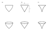
- FIG. 2 is a side view and a perspective view of a modified cap shape.
- the puncture cap 32 has been described as having a substantially conical shape, it may be not only a geometric cone (FIG. 2b), but also a bullet shape (FIG. 2a) in which the conical oblique line bulges in a convex shape, or the conical oblique line is recessed in a concave shape.
- a horn shape (FIG. 2c) may be used.
- the substantially conical shape also includes a polygonal pyramid that approximates a circle.
- FIG. 3 is a perspective view of a trocar having a retractable camera.
- FIG. 3A and FIG. 3B have different viewpoints.
- the trocar 2 also has a pipe portion 11 and a head portion 12 as a basic configuration, similar to the trocar 1. Further, the retractable camera mechanism 10 is provided.
- the retractable camera mechanism 10 includes a side opening 13, a shaft 14, a bearing 15, a switching mechanism 16, and a camera 17.
- a side opening 13 is provided at a position where the pipe portion 11 is surely inserted into the body.
- a shaft 14 is disposed in the axial direction of the pipe portion and along one end of the side opening 13.
- a plurality of bearings 15 are fixed to the inner wall of the pipe portion 11, and the bearings 15 fix the shaft 14 so as to be rotatable.
- the end of the shaft 14 extends outside the trocar.
- a switching mechanism 16 is provided at the end of the shaft 14. The switching mechanism 16 can be switched between a storage position and a deployment position, and is fixed at each position.
- the camera 17 is integrally and rigidly joined to the shaft 14 at a position corresponding to the opening 13. As a result, as the switching mechanism 16 and the shaft 14 are rotated, the camera 17 passes through the side opening 13 and is stored in the pipe portion, and a deployment position where the camera 17 is unfolded so as to be photographed outside the pipe portion. And can be switched.
- a cable 18 is connected to the camera 17, and the cable 18 is inserted through the trocar 1 and connected to an external image processing apparatus 6 (described later).
- the camera 17 is switched between a storage position stored in the trocar and a deployment position deployed so as to be photographable outside the trocar by the operation of the switching mechanism 16 (that is, the rotation of the shaft 14).
- a hinge opening / closing puncture cap is added to the trocar 2 having the retractable camera mechanism 10.
- the above is an example of the retractable camera mechanism 10, and the present invention is not limited to this.
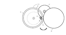
- FIGS. 4A and 4B are plan views of the trocar in the camera deployed position and the puncture cap open state as seen from below.
- the hinge mechanism 31 is provided at a position corresponding to the axis of the shaft 14. In other words, it is a common position in plan view.
- the hinge mechanism 31 is mechanically a point and has no size, but has a size when embodied. In general, the greater the size, the greater the strength. Therefore, the hinge mechanism 31 has a certain size.
- the inner space of the pipe 11 can be used widely.
- the entire trocar can be reduced in size.
- the hinge mechanism 31 is provided at a position opposite to the position corresponding to the axis of the shaft 14. In other words, the positions are opposite in plan view.
- the opposite position As an example that is not a common position, the opposite position. Thereby, the camera deployment position can be determined without being restricted by the interference between the camera 17 and the puncture cap 32. That is, the camera field of view can be reliably ensured.
- a position shifted by 90 degrees may be used.
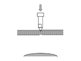
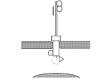
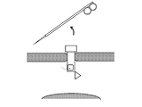
- FIGS. 5A to 5H are operation explanatory diagrams.
- the puncture cap 32 is in a closed state.
- the distal end (point) of the puncture cap 32 is brought into contact with a portion that becomes a hole in the abdominal wall. Then, force is applied to puncture the abdominal wall.
- the camera 17 is in the storage position (FIG. 5A).
- the camera 17 is switched to the deployment position (FIG. 5C). Thereby, an internal space is secured in the pipe portion 11.
- the camera 17 is in the unfolded position and images a surgical object (for example, an organ). Thereby, a real-time image is displayed on the monitor 7 (described later). Alternatively, the image is projected on the abdomen by the projector 8 (described later). The surgeon operates the forceps 4 while confirming the real-time image, and performs an operation (FIG. 5E).
- a surgical object for example, an organ.
- the forceps 4 is removed. Further, the camera 17 is switched to the storage position (FIG. 5F). As a result, the removal of the trocar is not an obstacle.
- the trocar 2 is removed so that the abdominal wall slides on the slope of the puncture cap 32.
- the hole in the abdominal wall naturally closes due to the elasticity of the abdominal wall (FIG. 5H).
- the present invention is also applicable to the trocar 1 (FIG. 1) that does not have the retractable camera mechanism 10.
- the operation of the trocar 1 may be performed by omitting the camera switching operation from the above operation.
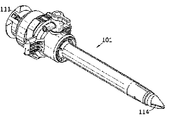
- FIG. 6A shows a general trocar 101 and an inner cylinder 111.
- FIG. 6B is a diagram in which the trocar 101 and the inner cylinder 111 are integrated.
- a general trocar 101 has a pipe portion 102 and a head portion 103 as a basic configuration.
- the inner cylinder 111 has a shaft portion 112 and a base portion 113 as a basic configuration.
- the shaft diameter is the same as or slightly smaller than the trocar pipe inner diameter, and the shaft length is slightly longer than the trocar pipe length.
- the shaft portion tip 114 is sharp like a ridge.
- the inner cylinder base 113 is approximately the same size as the trocar head 103 in plan view.
- the trocar 101 is integrated with the inner cylinder 111 to puncture the abdominal wall. After fixing the trocar at a predetermined position, the inner cylinder 111 is removed. Then, forceps are inserted through the trocar 101.
- 7A and 7B are operation explanatory diagrams when the inner cylinder 111 is applied to the trocar 2 having the retractable camera mechanism 10.
- the inner cylinder 111 cannot be inserted into the trocar 2 when the camera 17 is in the retracted position. Therefore, the camera 17 is set to the unfolded position, and the inner cylinder 111 is inserted into the trocar 2.
- the trocar 101 is integrated with the inner cylinder 111 to puncture the abdominal wall (FIG. 7A).
- the inner cylinder 111 is removed and the camera 17 is set to the storage position (FIG. 7B). Thereafter, the trocar 2 is inserted to a predetermined position.
- the trocar 2 is fixed by the elasticity of the abdominal wall.
- the inner cylinder 111 may be removed while the trocar 1 is being punctured into the abdominal wall. In that case, the subsequent puncture must be performed without the inner cylinder 111.
- the trocar insertion technique using the inner cylinder has problems related to the number of surgical procedures and the number of surgical instruments. In particular, when applied to the trocar 2 having the retractable camera mechanism 10, the number of medical procedures is further increased.
- the inner cylinder 111 is unnecessary, and there are few surgical procedures as follows.
- the operation of opening the puncture cap 32 is accompanied by the operation of inserting the forceps 4 into the pipe portion 11 (FIG. 5D).
- the operation of closing the puncture cap 32 is accompanied by the operation of gradually removing the trocar 2 (FIG. 5G). In other words, the puncture cap 32 is opened and closed semi-automatically.
- the puncture cap 32 is a part of the trocar 2 and the number of surgical instruments does not increase.
- the hinge mechanism 31 and the puncture cap 32 have a simple configuration, have a small management burden, and have few failures.
- the number of surgical procedures can be reduced, the number of surgical instruments can be reduced, and the burden on the operator can be reduced.
- FIG. 8 is a schematic configuration diagram of a surgery support system proposed by the inventor.
- the surgery support system 100 includes a forceps trocar 2 having a plurality of retractable camera mechanisms 10, a forceps 4, a laparoscope 5 (not shown), an image processing device 6, a monitor 7, a projector 8, and an optical sensor. 9.
- the forceps 4 is a kind of surgical instrument, and is used for grasping, suppressing, pulling, and cutting blood vessels and organs. Generally, it has a bowl shape, and the tip is actuated via a fulcrum by the rotation of the handle. The handle is closed and inserted into the forceps trocar 2.
- the laparoscope 5 is a kind of endoscopic instrument, and has a camera and a light source.
- the laparoscope 5 is inserted into the body through the trocar 3 for laparoscope. Note that the laparoscope 5 may be unnecessary if the performance of the retractable camera 17 is sufficiently high and an alternative light source can be secured.
- the image processing device 6 inputs an image obtained from the retractable camera 17 and an image obtained from the laparoscope 5 and synthesizes these images.
- the monitor 7 outputs a composite image synthesized by the image processing device 6.
- the projector 8 is provided above the operating table, and directly projects the composite image synthesized by the image processing device 6 onto the patient's abdomen.
- the optical sensor 9 measures the three-dimensional position of the trocar.
- the calculation for estimating the position of the camera from the position of the trocar may be performed by the optical sensor 9 or the image processing device 6.
- the surgery support system 100 creates a three-dimensional real-time image using a plurality of cameras.
- a three-dimensional image of a surgical target for example, an organ
- the operator's line of sight matches the direction of the operative field.
- the surgeon performs a laparoscopic operation just like a laparotomy.
- the monitor 7 is used as an auxiliary.
- This system is based on the conventional general laparoscopic surgery, and since there is no major change in the surgical method, the surgeon can make use of his previous knowledge and experience regarding surgery. Moreover, it is a simple structure using the trocar of this embodiment, and the existing surgery support system can be reused with a simple improvement.
- the trocar 2 having the retractable camera mechanism 10 is a core technology that realizes a virtual laparotomy using a three-dimensional real-time image.
- ⁇ Port> The above description is based on the assumption of laparoscopic surgery, but the present invention may be applied to thoracoscopic surgery.
- a surgical instrument called a trocar in laparoscopic surgery is called a port in thoracoscopic surgery. That is, the trocar and the port are almost the same.
- Trocar (with retractable camera mechanism) Reference Signs List 3 trocar for laparoscope 4 forceps 5 laparoscope 6 image processing device 7 monitor 8 projector 9 optical sensor 10 retractable camera mechanism 11 pipe portion 12 head portion 13 side opening portion 14 shaft 15 bearing 16 switching mechanism 17 camera 31 hinge mechanism 32 puncture Cap 100 Surgery support system 101 Trocar (prior art) 102 Pipe portion 103 Head portion 111 Inner cylinder 112 Shaft portion 113 Base portion 114 Shaft portion tip
Landscapes
- Health & Medical Sciences (AREA)
- Surgery (AREA)
- Life Sciences & Earth Sciences (AREA)
- Medical Informatics (AREA)
- Animal Behavior & Ethology (AREA)
- Engineering & Computer Science (AREA)
- Biomedical Technology (AREA)
- Heart & Thoracic Surgery (AREA)
- Pathology (AREA)
- Molecular Biology (AREA)
- Nuclear Medicine, Radiotherapy & Molecular Imaging (AREA)
- General Health & Medical Sciences (AREA)
- Public Health (AREA)
- Veterinary Medicine (AREA)
- Oral & Maxillofacial Surgery (AREA)
- Endoscopes (AREA)
- Surgical Instruments (AREA)
Abstract
内筒を用いるトロカール挿入技術に比べ、手術手順数を減らし、手術器具数を減らし、術者の負担を軽減する。トロカール1は、医療器具を体内に挿入するためのパイプ部11と、パイプ部11の上部に連続して設けられるヘッド部12を有し、パイプ部11を介して腹壁に設けられる。更に、パイプ部11先端に設けられたヒンジ機構31と、ヒンジ機構31を介してパイプ部11端面開口を開閉可能に設けられ、先端が尖った穿刺キャップ32とを備える。鉗子4をパイプ部11に挿入する動作に伴い、穿刺キャップ32は開状態となる。トロカール1を徐々に抜去する動作に伴い、穿刺キャップ32を閉状態となる。言い換えると、穿刺キャップ32の開閉は、半自動で行われる。
Description
本発明は、腹腔鏡下手術に用いるトロカールに関する。ただし、胸腔鏡下手術に用いる場合はポートという。
近年、患者のQOL(quality of life)維持・向上のために腹腔鏡下手術などの低侵襲外科手術が求められている。腹腔鏡下手術は腹腔内に炭酸ガスを注入して腹壁を膨らませ、手技のための空間と視野を確保する。そして腹壁に小さい孔を設け、トロカールと呼ばれる器具を挿入する。そこから腹腔鏡(CCDカメラ)や外科器具である鉗子を患者の体内に挿入し、腹腔鏡によってモニタに表示される映像を観察しながら手術を行うのが一般的である。
トロカールを腹壁に挿入する際には、内筒(詳細後述)を用いる。内筒の先端部は尖っており、内筒をトロカールに挿入し、トロカールを内筒と一体として、腹壁に穿刺する。トロカールを所定の位置に固定したのち、内筒を抜去する。そして、トロカールを介して鉗子を挿入する。内筒については、特許文献1に記載されている。
ところで、当然ながら手術に少しの失敗も許されない。術者は想像以上の緊張を強いられる。したがって、手術手順は少ない程、また、手術器具が少ない程、術者の負担は軽減される。
内筒は、トロカール挿入時に必須であるが、それ以外の用途はない。一方、内筒先端部は尖っており、誤って術者や患者を傷つけるおそれもある。慎重に取り扱わなくてはならず、術者の精神的な負担になる。
従って、内筒を用いないトロカール挿入技術により、手術手順数を減らし、手術器具数を減らし、術者の負担を軽減することが検討されている。
一方、本発明者は、格納式カメラを有するトロカールを提案している(詳細後述)。カメラは、格納位置と展開位置とに切り替わる。
内筒を、格納式カメラを有するトロカールに適用すると、以下のような不具合が生じる。
すなわち、カメラ格納位置では、内筒をトロカールに挿入できない。もしくは、カメラを充分小型化するか、トロカール径を充分大きくする必要がある。一方、カメラ展開位置では、カメラが障害となって、トロカールを腹部に挿入できない。術者は、複雑なカメラ位置切替操作をしなければならない(詳細後述)。
なお、格納式カメラを有するトロカールは、3次元リアルタイム画像を用いたバーチャル開腹手術を実現する中核技術である。
従って、格納式カメラを有するトロカールを改良することにより、トロカール挿入時の不具合を改善し、バーチャル開腹手術の実用性を向上させることが検討されている(詳細後述)。
本発明は上記課題を解決するものであり、内筒を用いないトロカール挿入技術により、手術手順数を減らし、手術器具数を減らし、術者の負担を軽減することを目的とする。
特に、格納式カメラを有するトロカールにおいて、挿入時の不具合を改善することを目的とする。
上記課題を解決する本発明は、医療器具を体内に挿入するためのパイプ部を有するトロカールであって、前記パイプ部先端に設けられたヒンジ機構と、前記ヒンジ機構を介してパイプ部端面開口を開閉可能に設けられ、先端が尖った穿刺キャップとを備える。
これにより、穿刺キャップは半自動的に開閉される。内筒がなくとも穿刺できるため、手術手順数を減らし、手術器具数を減らすことができる。
本発明において更に好ましくは、前記穿刺キャップの外縁が前記パイプ部端面に当接されることで、パイプ部端面開口は閉じられ、該穿刺キャップの外縁は、該パイプ部端面の外円に含まれる。
これにより、腹壁に引っかかることなく、トロカールを抜去できる。
本発明において更に好ましくは、前記穿刺キャップのキャップ高は、外縁直径の0.5~2.0倍である。
これにより、確実に穿刺できるとともに、腹腔内で穿刺キャップが障害となることを防止できる。
本発明において更に好ましくは、前記パイプ部の体内に挿入される位置に設けられる側面開口と、前記パイプ部の軸方向に、該側面開口一端部に沿って回動可能に固定され、かつ、端部がトロカール外に延長されるシャフトと、該シャフトに剛接合され、該シャフト端部の回動により、トロカール内に格納される格納位置とトロカール外に撮影可能に展開される展開位置とに切り替わるカメラとを有する格納式カメラ機構をさらに備える。
格納式カメラ機構を有するトロカールに内筒を適用すると、不具合が多い。本発明により改善できる。
本発明において更に好ましくは、前記ヒンジ機構は、該シャフトの軸に対応する位置に設けられる。
本発明において更に好ましくは、前記ヒンジ機構は、該シャフトの軸に対応する位置と対向する位置に設けられる。
小型化またはカメラ視野確保を目的として、最適な位置関係を選択する。
本発明において更に好ましくは、前記医療器具は鉗子である。
上記課題を解決する本発明は、医療器具を肺に挿入するためのパイプ部を有し、該パイプ部を介して胸壁に設けられるポートであって、前記パイプ部先端に設けられたヒンジ機構と、前記ヒンジ機構を介してパイプ部端面開口を開閉可能に設けられ、先端が尖った穿刺キャップとを備える。
本発明によれば、内筒を用いるトロカール挿入技術に比べ、手術手順数を減らし、手術器具数を減らし、術者の負担を軽減できる。
特に、格納式カメラを有するトロカールの挿入時の不具合を改善できる。
<穿刺キャップを有するトロカール>
本実施形態の構成について説明する。図1は、穿刺キャップを有するトロカールの斜視図である。図1(a)と図1(b)とは、視点が異なる。
トロカール1は、基本構成として、パイプ部11とヘッド部12とを有する。パイプ部11は、その大部分が腹壁の孔に挿入される。ヘッド部12はパイプ部11の上部に連続して設けられる。ヘッド部12は中空であり、その上部から鉗子が挿入可能になっている。また、詳細は省略するが、ヘッド部12は鉗子の挿抜時に空気の漏れを防止する密封機構と腹腔内に空気を送り込む送気機構とを備える。
本実施形態は、特徴的構成として、ヒンジ機構31と穿刺キャップ32を有する。
ヒンジ機構31は、パイプ部11先端に、設けられている。ヒンジ機構31の配置がパイプ部11端面開口と干渉しないようにすることにより、鉗子挿入の障害とならないようにする。
穿刺キャップ32は略円錐状であり、中実でもよいし、剛性が確保できれば、中空でもよい。略円錐状であるため、先端が尖っている。穿刺キャップ32は、ヒンジ機構31を介してパイプ部11端面開口を開閉可能に設けられている。
すなわち、穿刺キャップ32の外縁(略円錐底面の外周線)がパイプ部11端面に当接されることで、パイプ部11端面開口は閉じられる。この当接状態が解除されることで、パイプ部11端面開口は開かれる。
好ましくは、平面視にて、穿刺キャップ32の外縁がパイプ部11端面の外円に含まれる。更に好ましくは、穿刺キャップ32の外縁がパイプ部11端面の外円に一致する。これにより、トロカール抜去の際に、腹壁に引っかかることがない。
円錐高hは円錐底面直径Dの0.5~2.0倍であることが好ましい。円錐高hが高すぎると(2.0倍超)、トロカール挿入後に、腹腔内で穿刺キャップ32が障害となるおそれがある。円錐高hが低すぎると(0.5倍未満)、穿刺が難しくなるおそれがある。当該範囲にすることにより、確実に穿刺できるとともに、腹腔内で穿刺キャップが障害となることを防止できる。
図2はキャップ形状の変形例の側面図及び斜視図である。穿刺キャップ32を略円錐状と説明したが、幾何学的な円錐(図2b)だけでなく、円錐斜線が凸状に膨らんだ弾丸形状(図2a)でもよいし、円錐斜線が凹状にへこんだホーン形状(図2c)でもよい。また、略円錐状とは、円に近似した多角錐をも含む。
<格納式カメラ機構を有するトロカールへの適用>
格納式カメラ機構10を有するトロカールついて説明する。図3は、格納式カメラを有するトロカールの斜視図である。図3(a)と図3(b)とは、視点が異なる。
格納式カメラ機構10を有するトロカールついて説明する。図3は、格納式カメラを有するトロカールの斜視図である。図3(a)と図3(b)とは、視点が異なる。
トロカール2も、トロカール1と同様に、基本構成として、パイプ部11とヘッド部12とを有する。更に、格納式カメラ機構10を有する。格納式カメラ機構10は、側面開口部13とシャフト14と軸受15と切替機構16とカメラ17とから構成される。
パイプ部11の確実に体内に挿入される位置に側面開口部13が設けられている。パイプ部の軸方向であって、かつ、側面開口部13一端部に沿って、シャフト14が配置される。パイプ部11内壁には複数の軸受15が固定されており、軸受15はシャフト14を回動可能に固定している。シャフト14端部はトロカール外に延長している。シャフト14端部には、切替機構16が設けられている。切替機構16は、格納位置と展開位置に切替可能であり、各位置で固定される。
シャフト14には開口部13に対応する位置に、カメラ17が一体として剛接合されている。これにより、切替機構16およびシャフト14の回動に伴って、カメラ17は、側面開口部13を通過して、パイプ部内に格納される格納位置とパイプ部外に撮影可能に展開される展開位置とに切替可能に回動する。カメラ17にはケーブル18が接続されており、ケーブル18はトロカール1内を挿通して、外部の画像処理装置6(後述)と接続している。
なお、ケーブル18をシャフト14に沿って配置するか、シャフト14を中空にし、シャフト14内にケーブル18を配置すれば、鉗子挿入時にケーブル18を切断する危険性が無くなるため、更に好ましい。
カメラ17は、切替機構16の動作(すなわちシャフト14の回動)により、トロカール内に格納される格納位置とトロカール外に撮影可能に展開される展開位置とに切り替わる。
本実施形態は、格納式カメラ機構10を有するトロカール2にヒンジ開閉式の穿刺キャップを付加したものである。なお、上記は格納式カメラ機構10の一例を示したものであり、これに限定されない。
<ヒンジ機構とシャフトとの位置関係の検討>
ヒンジ機構31とシャフト14の軸の平面視における位置関係について説明する。図4Aおよび図4Bは、カメラ展開位置かつ穿刺キャップ開状態のトロカールを下方からみた平面図である。
ヒンジ機構31とシャフト14の軸の平面視における位置関係について説明する。図4Aおよび図4Bは、カメラ展開位置かつ穿刺キャップ開状態のトロカールを下方からみた平面図である。
図4Aにおいて、ヒンジ機構31は、シャフト14の軸に対応する位置に設けられる。言い換えると、平面視にて共通の位置となる。
ヒンジ機構31は、力学的には点でありサイズがないが、具現化するとサイズを有する。一般に、サイズが大きくなる程、強度は増す。従って、ヒンジ機構31はある程度のサイズを有する。
共通位置とすることにより、パイプ11の内空を広く利用できる。鉗子を挿入するのに充分な内空が確保されている場合は、トロカール全体の小型化を図ることができる。
ただし、カメラ17と穿刺キャップ32とが干渉する位置関係にならないように、切替機構16を適切に操作する必要がある。
図4Bにおいて、ヒンジ機構31は、シャフト14の軸に対応する位置と対向する位置に設けられる。言い換えると、平面視にて反対の位置となる。
シャフト14やヒンジ機構31が充分に小型化できる等により、鉗子を挿入するのに充分なパイプ11内空が確保されている場合は、共通位置とするメリットは少ない。
共通位置でない例として、反対位置とする。これにより、カメラ17と穿刺キャップ32との干渉による制約を受けることなく、カメラ展開位置を決定できる。すなわち、カメラ視野を確実に確保できる。共通位置でない例として、90度ずれた位置でもよい。
<トロカールへの動作>
トロカール2の動作について、動作説明図である図5A~図5Hを用いて説明する。
トロカール2の動作について、動作説明図である図5A~図5Hを用いて説明する。
穿刺キャップ32は閉状態にある。穿刺キャップ32先端(尖部)を腹壁の孔となる箇所に当接する。そして、力を加えて、腹壁に穿刺する。このとき、カメラ17は格納位置にある(図5A)。
更に力を加えて、トロカール2を所定の位置まで挿入する。トロカール2は腹壁の弾力(収縮圧)により固定される(図5B)。カメラ17が格納位置にあるため、トロカール挿入の障害となることはない。
その後、カメラ17を展開位置に切り替える(図5C)。これにより、パイプ部11に、内空が確保される。
パイプ部11に鉗子4を挿入する。このとき、鉗子先端が穿刺キャップ32の裏側に接触することで、穿刺キャップ32が開状態になる(図5D)。
カメラ17は展開位置にあり、手術対象(例えば臓器)を撮影する。これにより、リアルタイム画像がモニタ7(後述)に表示される。または、プロジェクタ8(後述)により腹部に投影される。術者は、リアルタイム画像を確認しながら、鉗子4を操作し、手術を行う(図5E)。
術後、鉗子4を抜去する。また、カメラ17を格納位置に切り替える(図5F)。これにより、トロカール抜去の障害となることはない。
トロカール2を徐々に抜去する。このとき、腹壁の弾力は、孔を閉じるように作用する。すなわち、穿刺キャップ32斜面に力が作用する。この作用により、穿刺キャップ32は徐々に閉じ状態になる(図5G)。なお、このとき、穿刺キャップ32とパイプ部11端面との間に腹壁が挟まれないことを、動物実験により確認している。
腹壁が穿刺キャップ32斜面を滑るように、トロカール2は抜去される。トロカール2が完全に抜去されると、腹壁の孔は、腹壁の弾力により自然と閉じる(図5H)。
なお、本発明は、格納式カメラ機構10を有しないトロカール1(図1)にも適用可能である。トロカール1の動作は、上記動作からカメラ切替動作を省略すればよい。
<従来技術の課題>
一般に、トロカールを腹壁に挿入する際には、内筒を用いる。図6Aは一般的なトロカール101と内筒111である。図6Bはトロカール101と内筒111が一体化した図である。
一般に、トロカールを腹壁に挿入する際には、内筒を用いる。図6Aは一般的なトロカール101と内筒111である。図6Bはトロカール101と内筒111が一体化した図である。
一般的なトロカール101は、基本構成として、パイプ部102とヘッド部103とを有する。
内筒111は、基本構成として、シャフト部112と基部113とを有する。シャフト径は、トロカールのパイプ内径と同程度またはやや小さく、シャフト長は、トロカールのパイプ長よりやや長い。シャフト部先端114は槍の様に尖っている。内筒基部113は、トロカールヘッド部103と平面視にて同程度のサイズである。
内筒シャフト部112をトロカールパイプ部102に挿入し、内筒基部113をトロカールヘッド部103に係合させると、内筒111とトロカール101が一体化する。このとき、シャフト部先端114が突出している。
トロカール101を内筒111と一体として、腹壁に穿刺する。トロカールを所定の位置に固定したのち、内筒111を抜去する。そして、トロカール101を介して鉗子を挿入する。
すなわち、トロカール101と内筒111とを一体化する手順と、内筒111を抜去する手順とが必須である。一方で、手術手順を減らし、手術器具数を減らすことで、術者の負担を軽減することが検討されている。
しかし、内筒111を、格納式カメラ機構10を有するトロカール2に適用すると、以下のように、医療手順がさらに複雑になり、術者の負担は加重される。
図7Aおよび図7Bは、内筒111を、格納式カメラ機構10を有するトロカール2に適用する場合の動作説明図である。
すなわち、カメラ17が格納位置では、内筒111をトロカール2に挿入できない。したがって、カメラ17を展開位置にし、内筒111をトロカール2に挿入する。トロカール101を内筒111と一体として、腹壁に穿刺する(図7A)。
しかし、一方、カメラ17が展開位置のままでは、カメラ17が障害となって、トロカール2をそれ以上挿入できない。したがって、内筒111を抜去し、カメラ17を格納位置とする(図7B)。その後、トロカール2を所定の位置まで挿入する。トロカール2は腹壁の弾力により固定される。
このように、術者は、複雑なカメラ位置の切替操作をしなければならない。
更に、トロカール1を腹壁に穿刺している途中で、内筒111を抜去する場合もあり得る。その場合、その後の穿刺を内筒111なしで行わなければならない。
<効果>
従来技術と比較することにより本実施形態の効果を説明する。内筒を用いるトロカール挿入技術は、手術手順数および手術器具数に係る課題があった。特に、格納式カメラ機構10を有するトロカール2に適用すると、医療手順数がさらに増える。
従来技術と比較することにより本実施形態の効果を説明する。内筒を用いるトロカール挿入技術は、手術手順数および手術器具数に係る課題があった。特に、格納式カメラ機構10を有するトロカール2に適用すると、医療手順数がさらに増える。
これに対し本実施形態では、内筒111が不要であり、以下の様に手術手順も少ない。
穿刺キャップ32を開状態とする動作は、鉗子4をパイプ部11に挿入する動作に伴うものである(図5D)。また、穿刺キャップ32を閉状態とする動作は、トロカール2を徐々に抜去する動作に伴うものである(図5G)。言い換えると、穿刺キャップ32の開閉は、半自動で行われる。
穿刺キャップ32はトロカール2の一部であり、手術器具数は増えない。また、ヒンジ機構31および穿刺キャップ32は簡素な構成であり、管理負担が少なく、故障も少ない。
すなわち、内筒を用いるトロカール挿入技術に比べ、手術手順数を減らし、手術器具数を減らし、術者の負担を軽減できる。
<手術支援システム(バーチャル開腹手術)>
図8は発明者が提案する手術支援システムの概略構成図である。手術支援システム100は、複数の格納式カメラ機構10を有する鉗子用トロカール2と、鉗子4と、腹腔鏡5(図示省略)と、画像処理装置6と、モニタ7と、プロジェクタ8と、光学センサ9とを備える。
図8は発明者が提案する手術支援システムの概略構成図である。手術支援システム100は、複数の格納式カメラ機構10を有する鉗子用トロカール2と、鉗子4と、腹腔鏡5(図示省略)と、画像処理装置6と、モニタ7と、プロジェクタ8と、光学センサ9とを備える。
鉗子4は、手術器具の一種であり、血管や臓器等を、掴んだり、抑えたり、引っ張ったり、切断したりするのに用いられる。一般的に鋏形状をしており、持手部の回動により、支点を介して先端部が作動する。持手部を閉状態にし、鉗子用トロカール2に挿通させる。
腹腔鏡5は、内視鏡器具の一種であり、カメラと光源を有している。腹腔鏡5は腹腔鏡用トロカール3を挿通して体内に挿入される。なお、格納式カメラ17の性能が充分高く、代替光源を確保できれば、腹腔鏡5を不要としても良い。
画像処理装置6は、格納式カメラ17から得られた画像と腹腔鏡5から得られた画像を入力し、これらの画像を合成処理する。
モニタ7は、画像処理装置6により合成処理された合成画像を出力する。
プロジェクタ8は、手術台の上方に設けられ、画像処理装置6により合成処理された合成画像を患者の腹部に直接投影する。
光学センサ9は、トロカールの3次元位置を計測する。トロカールの位置からカメラの位置を推定する演算については、光学センサ9が行っても良いし、画像処理装置6が行っても良い。
手術支援システム100は、複数のカメラを用いて、3次元リアルタイム画像を作成する。患者の腹部には、手術対象(例えば臓器)の3次元画像が再現される。術者の視線と術野の方向は一致している。術者は、開腹手術をするように、腹腔鏡下手術をおこなう。詳細画像を見たいときは、補助的にモニタ7を用いる。
本システムは、格納式カメラ機構10を有するトロカール2を用いるため、新たに腹壁に孔をあける必要はなく、低侵襲性を維持できる。
本システムは、従来の一般的な腹腔鏡下手術を基礎とするものであり、手術方式の大きな変更がないため、術者はこれまでの手術に関する知識と経験をそのまま生かすことができる。また、本実施形態のトロカールを用いた簡素な構成であり、既存の手術支援システムを簡単な改良で再利用することができる。
一方、腹腔鏡下手術に慣れていないが、開腹手術の経験豊富な術者も、これまでの手術に関する知識と経験をそのまま生かすことができる。
ここで、上述の通り、格納式カメラ機構10を有するトロカール2は、3次元リアルタイム画像を用いたバーチャル開腹手術を実現する中核技術である。
従って、トロカール挿入時の不具合を改善することで、バーチャル開腹手術の実用性を向上させることができる。
<ポート>
以上、腹腔鏡下手術を前提に説明したが、本発明は、胸腔鏡下手術に適用しても良い。ただし、腹腔鏡下手術においてトロカールと呼ばれる手術器具は、胸腔鏡下手術においてポートと呼ばれる。すなわち、トロカールとポートはほぼ同じものである。
以上、腹腔鏡下手術を前提に説明したが、本発明は、胸腔鏡下手術に適用しても良い。ただし、腹腔鏡下手術においてトロカールと呼ばれる手術器具は、胸腔鏡下手術においてポートと呼ばれる。すなわち、トロカールとポートはほぼ同じものである。
1 トロカール
2 トロカール(格納式カメラ機構付)
3 腹腔鏡用トロカール
4 鉗子
5 腹腔鏡
6 画像処理装置
7 モニタ
8 プロジェクタ
9 光学センサ
10 格納式カメラ機構
11 パイプ部
12 ヘッド部
13 側面開口部
14 シャフト
15 軸受
16 切替機構
17 カメラ
31 ヒンジ機構
32 穿刺キャップ
100 手術支援システム
101 トロカール(従来技術)
102 パイプ部
103 ヘッド部
111 内筒
112 シャフト部
113 基部
114 シャフト部先端
2 トロカール(格納式カメラ機構付)
3 腹腔鏡用トロカール
4 鉗子
5 腹腔鏡
6 画像処理装置
7 モニタ
8 プロジェクタ
9 光学センサ
10 格納式カメラ機構
11 パイプ部
12 ヘッド部
13 側面開口部
14 シャフト
15 軸受
16 切替機構
17 カメラ
31 ヒンジ機構
32 穿刺キャップ
100 手術支援システム
101 トロカール(従来技術)
102 パイプ部
103 ヘッド部
111 内筒
112 シャフト部
113 基部
114 シャフト部先端
Claims (7)
- 医療器具を体内に挿入するためのパイプ部を有するトロカールであって、
前記パイプ部先端に設けられたヒンジ機構と、
前記ヒンジ機構を介してパイプ部端面開口を開閉可能に設けられ、先端が尖った穿刺キャップと
を備えることを特徴とするトロカール。 - 前記穿刺キャップの外縁が前記パイプ部端面に当接されることで、パイプ部端面開口は閉じられ、
該穿刺キャップの外縁は、該パイプ部端面の外円に含まれる
ことを特徴とする請求項1記載のトロカール。 - 前記パイプ部の体内に挿入される位置に設けられる側面開口と、
前記パイプ部の軸方向に、該側面開口一端部に沿って回動可能に固定され、かつ、端部がトロカール外に延長されるシャフトと、
該シャフトに剛接合され、該シャフト端部の回動により、トロカール内に格納される格納位置とトロカール外に撮影可能に展開される展開位置とに切り替わるカメラと
を有する格納式カメラ機構
をさらに備えること
ことを特徴とする請求項1または2記載のトロカール。 - 前記ヒンジ機構は、該シャフトの軸に対応する位置に設けられる
ことを特徴とする請求項3記載のトロカール。 - 前記ヒンジ機構は、該シャフトの軸に対応する位置と対向する位置に設けられる
ことを特徴とする請求項3記載のトロカール。 - 前記医療器具は鉗子である
ことを特徴とする請求項1~5いずれか記載のトロカール。 - 医療器具を肺に挿入するためのパイプ部を有し、該パイプ部を介して胸壁に設けられるポートであって、
前記パイプ部先端に設けられたヒンジ機構と、
前記ヒンジ機構を介してパイプ部端面開口を開閉可能に設けられ、先端が尖った穿刺キャップと
を備えることを特徴とするポート。
Applications Claiming Priority (2)
| Application Number | Priority Date | Filing Date | Title |
|---|---|---|---|
| JP2013-104526 | 2013-05-16 | ||
| JP2013104526A JP2016135160A (ja) | 2013-05-16 | 2013-05-16 | トロカールおよびポート |
Publications (1)
| Publication Number | Publication Date |
|---|---|
| WO2014185333A1 true WO2014185333A1 (ja) | 2014-11-20 |
Family
ID=51898311
Family Applications (1)
| Application Number | Title | Priority Date | Filing Date |
|---|---|---|---|
| PCT/JP2014/062339 Ceased WO2014185333A1 (ja) | 2013-05-16 | 2014-05-08 | トロカールおよびポート |
Country Status (2)
| Country | Link |
|---|---|
| JP (1) | JP2016135160A (ja) |
| WO (1) | WO2014185333A1 (ja) |
Cited By (6)
| Publication number | Priority date | Publication date | Assignee | Title |
|---|---|---|---|---|
| CN106333734A (zh) * | 2016-10-08 | 2017-01-18 | 江苏风和医疗器材有限公司 | 无芯穿刺器 |
| CN106344126A (zh) * | 2016-10-08 | 2017-01-25 | 江苏风和医疗器材有限公司 | 无芯穿刺器 |
| CN106388912A (zh) * | 2016-10-08 | 2017-02-15 | 江苏风和医疗器材有限公司 | 无芯穿刺器 |
| CN109646081A (zh) * | 2017-10-12 | 2019-04-19 | 江苏风和医疗器材股份有限公司 | 一种无芯穿刺器的前部的组装方法 |
| CN113476117A (zh) * | 2021-08-06 | 2021-10-08 | 施爱德(厦门)医疗器材有限公司 | 带全景影像功能的穿刺套管 |
| JP2023019216A (ja) * | 2021-07-28 | 2023-02-09 | 国立大学法人千葉大学 | 体腔内観察システム、医療器具、制御装置、情報取得方法およびプログラム |
Families Citing this family (1)
| Publication number | Priority date | Publication date | Assignee | Title |
|---|---|---|---|---|
| US11129680B2 (en) * | 2017-12-21 | 2021-09-28 | Cilag Gmbh International | Surgical instrument comprising a projector |
Citations (7)
| Publication number | Priority date | Publication date | Assignee | Title |
|---|---|---|---|---|
| JPS5668504U (ja) * | 1979-10-31 | 1981-06-06 | ||
| JPS59500004U (ja) * | 1982-03-16 | 1984-03-22 | ||
| JP2000262527A (ja) * | 1999-03-18 | 2000-09-26 | Hitachi Ltd | 手術用術具挿入装置及び手術用支援装置 |
| JP2002209835A (ja) * | 2001-01-15 | 2002-07-30 | Fuji Photo Optical Co Ltd | 体腔内診断装置 |
| JP2006503641A (ja) * | 2002-10-23 | 2006-02-02 | インテリムド サージカル ソリューションズ、エルエルシー | 直接視ポート部位ディセクター |
| JP2008504886A (ja) * | 2004-06-29 | 2008-02-21 | アプライド メディカル リソーシーズ コーポレイション | 通気用の光学外科手術器具 |
| JP2010519954A (ja) * | 2007-02-28 | 2010-06-10 | タイコ ヘルスケア グループ リミテッド パートナーシップ | 手術用視覚アクセス装置 |
-
2013
- 2013-05-16 JP JP2013104526A patent/JP2016135160A/ja active Pending
-
2014
- 2014-05-08 WO PCT/JP2014/062339 patent/WO2014185333A1/ja not_active Ceased
Patent Citations (7)
| Publication number | Priority date | Publication date | Assignee | Title |
|---|---|---|---|---|
| JPS5668504U (ja) * | 1979-10-31 | 1981-06-06 | ||
| JPS59500004U (ja) * | 1982-03-16 | 1984-03-22 | ||
| JP2000262527A (ja) * | 1999-03-18 | 2000-09-26 | Hitachi Ltd | 手術用術具挿入装置及び手術用支援装置 |
| JP2002209835A (ja) * | 2001-01-15 | 2002-07-30 | Fuji Photo Optical Co Ltd | 体腔内診断装置 |
| JP2006503641A (ja) * | 2002-10-23 | 2006-02-02 | インテリムド サージカル ソリューションズ、エルエルシー | 直接視ポート部位ディセクター |
| JP2008504886A (ja) * | 2004-06-29 | 2008-02-21 | アプライド メディカル リソーシーズ コーポレイション | 通気用の光学外科手術器具 |
| JP2010519954A (ja) * | 2007-02-28 | 2010-06-10 | タイコ ヘルスケア グループ リミテッド パートナーシップ | 手術用視覚アクセス装置 |
Cited By (12)
| Publication number | Priority date | Publication date | Assignee | Title |
|---|---|---|---|---|
| CN106333734A (zh) * | 2016-10-08 | 2017-01-18 | 江苏风和医疗器材有限公司 | 无芯穿刺器 |
| CN106344126A (zh) * | 2016-10-08 | 2017-01-25 | 江苏风和医疗器材有限公司 | 无芯穿刺器 |
| CN106388912A (zh) * | 2016-10-08 | 2017-02-15 | 江苏风和医疗器材有限公司 | 无芯穿刺器 |
| CN106388912B (zh) * | 2016-10-08 | 2019-01-04 | 江苏风和医疗器材股份有限公司 | 无芯穿刺器 |
| CN106344126B (zh) * | 2016-10-08 | 2019-02-15 | 江苏风和医疗器材股份有限公司 | 无芯穿刺器 |
| CN106333734B (zh) * | 2016-10-08 | 2019-05-31 | 江苏风和医疗器材股份有限公司 | 无芯穿刺器 |
| CN110025365A (zh) * | 2016-10-08 | 2019-07-19 | 江苏风和医疗器材股份有限公司 | 无芯穿刺器 |
| CN109646081A (zh) * | 2017-10-12 | 2019-04-19 | 江苏风和医疗器材股份有限公司 | 一种无芯穿刺器的前部的组装方法 |
| CN109646081B (zh) * | 2017-10-12 | 2021-07-06 | 江苏风和医疗器材股份有限公司 | 一种无芯穿刺器的前部的组装方法 |
| JP2023019216A (ja) * | 2021-07-28 | 2023-02-09 | 国立大学法人千葉大学 | 体腔内観察システム、医療器具、制御装置、情報取得方法およびプログラム |
| JP7722638B2 (ja) | 2021-07-28 | 2025-08-13 | 国立大学法人千葉大学 | 体腔内観察システム、医療器具、制御装置、情報取得方法およびプログラム |
| CN113476117A (zh) * | 2021-08-06 | 2021-10-08 | 施爱德(厦门)医疗器材有限公司 | 带全景影像功能的穿刺套管 |
Also Published As
| Publication number | Publication date |
|---|---|
| JP2016135160A (ja) | 2016-07-28 |
Similar Documents
| Publication | Publication Date | Title |
|---|---|---|
| WO2014185333A1 (ja) | トロカールおよびポート | |
| JP2014132979A (ja) | トロカールおよび手術支援システム | |
| JP3213927U (ja) | 外科手術器具 | |
| US6908427B2 (en) | Flexible endoscope capsule | |
| JP3429685B2 (ja) | 内視鏡案内管 | |
| US20090131751A1 (en) | Anal surgical instrument guides | |
| JP2021166818A (ja) | 回転補助ポート | |
| JP5770194B2 (ja) | 取り付け式エンドエフェクターを有する腹腔鏡器具 | |
| CN107361827A (zh) | 光学套管针可视化系统及设备 | |
| US20170296228A1 (en) | Trocar System | |
| JP2010069094A (ja) | 医療機器 | |
| JP2005518862A (ja) | 穿刺部位閉鎖装置関連出願及び優先権主張本出願は2002年3月1日に出願された発明の名称”LaparoscopicPortSiteFascialClosureDevice”の同時係属米国出願番号第10/086,318号に対して優先権を主張し、その全体が参照により組み込まれるものである。 | |
| JP2016016053A (ja) | トロカール組立体 | |
| CN113476117B (zh) | 带全景影像功能的穿刺套管 | |
| JP7200939B2 (ja) | 手術システム、制御方法、手術機器、並びにプログラム | |
| JP2015136460A (ja) | トロカールおよびポート | |
| EP2522270A1 (en) | Pivoted three-dimensional video endoscope | |
| CN105796162A (zh) | 一种可视穿刺器 | |
| US9999443B2 (en) | Instrument head single loader | |
| CN105640600A (zh) | 腹腔镜术后戳卡孔缝合装置 | |
| JP5372301B1 (ja) | 医療用ポート | |
| JP4967096B2 (ja) | 内視鏡、内視鏡アタッチメント、および、内視鏡装置 | |
| JP2018171373A (ja) | 内視鏡補助装置 | |
| KR101902861B1 (ko) | 카테터 | |
| US20130225920A1 (en) | Surgical support assembly |
Legal Events
| Date | Code | Title | Description |
|---|---|---|---|
| 121 | Ep: the epo has been informed by wipo that ep was designated in this application |
Ref document number: 14797538 Country of ref document: EP Kind code of ref document: A1 |
|
| NENP | Non-entry into the national phase |
Ref country code: DE |
|
| 122 | Ep: pct application non-entry in european phase |
Ref document number: 14797538 Country of ref document: EP Kind code of ref document: A1 |
|
| NENP | Non-entry into the national phase |
Ref country code: JP |