WO2014185248A1 - 低温液化ガスタンク - Google Patents
低温液化ガスタンク Download PDFInfo
- Publication number
- WO2014185248A1 WO2014185248A1 PCT/JP2014/061590 JP2014061590W WO2014185248A1 WO 2014185248 A1 WO2014185248 A1 WO 2014185248A1 JP 2014061590 W JP2014061590 W JP 2014061590W WO 2014185248 A1 WO2014185248 A1 WO 2014185248A1
- Authority
- WO
- WIPO (PCT)
- Prior art keywords
- gas
- low
- storage tank
- temperature liquefied
- liquefied gas
- Prior art date
- Legal status (The legal status is an assumption and is not a legal conclusion. Google has not performed a legal analysis and makes no representation as to the accuracy of the status listed.)
- Ceased
Links
Images


Classifications
-
- F—MECHANICAL ENGINEERING; LIGHTING; HEATING; WEAPONS; BLASTING
- F25—REFRIGERATION OR COOLING; COMBINED HEATING AND REFRIGERATION SYSTEMS; HEAT PUMP SYSTEMS; MANUFACTURE OR STORAGE OF ICE; LIQUEFACTION SOLIDIFICATION OF GASES
- F25J—LIQUEFACTION, SOLIDIFICATION OR SEPARATION OF GASES OR GASEOUS OR LIQUEFIED GASEOUS MIXTURES BY PRESSURE AND COLD TREATMENT OR BY BRINGING THEM INTO THE SUPERCRITICAL STATE
- F25J1/00—Processes or apparatus for liquefying or solidifying gases or gaseous mixtures
- F25J1/0002—Processes or apparatus for liquefying or solidifying gases or gaseous mixtures characterised by the fluid to be liquefied
- F25J1/0022—Hydrocarbons, e.g. natural gas
- F25J1/0025—Boil-off gases "BOG" from storages
-
- F—MECHANICAL ENGINEERING; LIGHTING; HEATING; WEAPONS; BLASTING
- F17—STORING OR DISTRIBUTING GASES OR LIQUIDS
- F17C—VESSELS FOR CONTAINING OR STORING COMPRESSED, LIQUEFIED OR SOLIDIFIED GASES; FIXED-CAPACITY GAS-HOLDERS; FILLING VESSELS WITH, OR DISCHARGING FROM VESSELS, COMPRESSED, LIQUEFIED, OR SOLIDIFIED GASES
- F17C13/00—Details of vessels or of the filling or discharging of vessels
-
- F—MECHANICAL ENGINEERING; LIGHTING; HEATING; WEAPONS; BLASTING
- F17—STORING OR DISTRIBUTING GASES OR LIQUIDS
- F17C—VESSELS FOR CONTAINING OR STORING COMPRESSED, LIQUEFIED OR SOLIDIFIED GASES; FIXED-CAPACITY GAS-HOLDERS; FILLING VESSELS WITH, OR DISCHARGING FROM VESSELS, COMPRESSED, LIQUEFIED, OR SOLIDIFIED GASES
- F17C9/00—Methods or apparatus for discharging liquefied or solidified gases from vessels not under pressure
- F17C9/02—Methods or apparatus for discharging liquefied or solidified gases from vessels not under pressure with change of state, e.g. vaporisation
-
- F—MECHANICAL ENGINEERING; LIGHTING; HEATING; WEAPONS; BLASTING
- F17—STORING OR DISTRIBUTING GASES OR LIQUIDS
- F17C—VESSELS FOR CONTAINING OR STORING COMPRESSED, LIQUEFIED OR SOLIDIFIED GASES; FIXED-CAPACITY GAS-HOLDERS; FILLING VESSELS WITH, OR DISCHARGING FROM VESSELS, COMPRESSED, LIQUEFIED, OR SOLIDIFIED GASES
- F17C2203/00—Vessel construction, in particular walls or details thereof
- F17C2203/06—Materials for walls or layers thereof; Properties or structures of walls or their materials
- F17C2203/0602—Wall structures; Special features thereof
- F17C2203/0604—Liners
-
- F—MECHANICAL ENGINEERING; LIGHTING; HEATING; WEAPONS; BLASTING
- F17—STORING OR DISTRIBUTING GASES OR LIQUIDS
- F17C—VESSELS FOR CONTAINING OR STORING COMPRESSED, LIQUEFIED OR SOLIDIFIED GASES; FIXED-CAPACITY GAS-HOLDERS; FILLING VESSELS WITH, OR DISCHARGING FROM VESSELS, COMPRESSED, LIQUEFIED, OR SOLIDIFIED GASES
- F17C2203/00—Vessel construction, in particular walls or details thereof
- F17C2203/06—Materials for walls or layers thereof; Properties or structures of walls or their materials
- F17C2203/0634—Materials for walls or layers thereof
- F17C2203/0678—Concrete
-
- F—MECHANICAL ENGINEERING; LIGHTING; HEATING; WEAPONS; BLASTING
- F17—STORING OR DISTRIBUTING GASES OR LIQUIDS
- F17C—VESSELS FOR CONTAINING OR STORING COMPRESSED, LIQUEFIED OR SOLIDIFIED GASES; FIXED-CAPACITY GAS-HOLDERS; FILLING VESSELS WITH, OR DISCHARGING FROM VESSELS, COMPRESSED, LIQUEFIED, OR SOLIDIFIED GASES
- F17C2221/00—Handled fluid, in particular type of fluid
- F17C2221/03—Mixtures
- F17C2221/032—Hydrocarbons
- F17C2221/033—Methane, e.g. natural gas, CNG, LNG, GNL, GNC, PLNG
-
- F—MECHANICAL ENGINEERING; LIGHTING; HEATING; WEAPONS; BLASTING
- F17—STORING OR DISTRIBUTING GASES OR LIQUIDS
- F17C—VESSELS FOR CONTAINING OR STORING COMPRESSED, LIQUEFIED OR SOLIDIFIED GASES; FIXED-CAPACITY GAS-HOLDERS; FILLING VESSELS WITH, OR DISCHARGING FROM VESSELS, COMPRESSED, LIQUEFIED, OR SOLIDIFIED GASES
- F17C2221/00—Handled fluid, in particular type of fluid
- F17C2221/03—Mixtures
- F17C2221/032—Hydrocarbons
- F17C2221/035—Propane butane, e.g. LPG, GPL
-
- F—MECHANICAL ENGINEERING; LIGHTING; HEATING; WEAPONS; BLASTING
- F17—STORING OR DISTRIBUTING GASES OR LIQUIDS
- F17C—VESSELS FOR CONTAINING OR STORING COMPRESSED, LIQUEFIED OR SOLIDIFIED GASES; FIXED-CAPACITY GAS-HOLDERS; FILLING VESSELS WITH, OR DISCHARGING FROM VESSELS, COMPRESSED, LIQUEFIED, OR SOLIDIFIED GASES
- F17C2223/00—Handled fluid before transfer, i.e. state of fluid when stored in the vessel or before transfer from the vessel
- F17C2223/01—Handled fluid before transfer, i.e. state of fluid when stored in the vessel or before transfer from the vessel characterised by the phase
- F17C2223/0146—Two-phase
- F17C2223/0153—Liquefied gas, e.g. LPG, GPL
-
- F—MECHANICAL ENGINEERING; LIGHTING; HEATING; WEAPONS; BLASTING
- F17—STORING OR DISTRIBUTING GASES OR LIQUIDS
- F17C—VESSELS FOR CONTAINING OR STORING COMPRESSED, LIQUEFIED OR SOLIDIFIED GASES; FIXED-CAPACITY GAS-HOLDERS; FILLING VESSELS WITH, OR DISCHARGING FROM VESSELS, COMPRESSED, LIQUEFIED, OR SOLIDIFIED GASES
- F17C2223/00—Handled fluid before transfer, i.e. state of fluid when stored in the vessel or before transfer from the vessel
- F17C2223/01—Handled fluid before transfer, i.e. state of fluid when stored in the vessel or before transfer from the vessel characterised by the phase
- F17C2223/0146—Two-phase
- F17C2223/0153—Liquefied gas, e.g. LPG, GPL
- F17C2223/0161—Liquefied gas, e.g. LPG, GPL cryogenic, e.g. LNG, GNL, PLNG
-
- F—MECHANICAL ENGINEERING; LIGHTING; HEATING; WEAPONS; BLASTING
- F17—STORING OR DISTRIBUTING GASES OR LIQUIDS
- F17C—VESSELS FOR CONTAINING OR STORING COMPRESSED, LIQUEFIED OR SOLIDIFIED GASES; FIXED-CAPACITY GAS-HOLDERS; FILLING VESSELS WITH, OR DISCHARGING FROM VESSELS, COMPRESSED, LIQUEFIED, OR SOLIDIFIED GASES
- F17C2265/00—Effects achieved by gas storage or gas handling
- F17C2265/03—Treating the boil-off
- F17C2265/032—Treating the boil-off by recovery
- F17C2265/033—Treating the boil-off by recovery with cooling
- F17C2265/034—Treating the boil-off by recovery with cooling with condensing the gas phase
Definitions
- the present invention relates to a low-temperature liquefied gas tank.
- This application claims priority based on Japanese Patent Application No. 2013-103287 for which it applied to Japan on May 15, 2013, and uses the content here.
- a low temperature liquefaction tank provided with a storage tank for storing a low temperature liquefied gas such as LNG (liquefied natural gas), boil-off gas (hereinafter referred to as BOG) generated by vaporizing the low temperature liquefied gas is reliquefied. It is returned to liquefied gas as a product form. That is, the generated BOG is compressed and cooled by a reliquefaction facility to be reliquefied, and once separated by a gas-liquid separation drum, the gas is returned to the upper part of the storage tank (for example, see Patent Document 1). ).
- LNG liquefied natural gas
- BOG boil-off gas
- the vaporized gas contains a relatively large amount of nitrogen due to the difference in boiling point between the low-temperature liquefied gas and nitrogen. That is, the vaporized gas returned to the storage tank has a high nitrogen concentration.
- nitrogen is returned to the upper part of the storage tank, that is, above the liquid level of the low-temperature liquefied gas, so that it is mixed with the BOG generated in the storage tank and sent again to the reliquefaction facility.
- the nitrogen concentration in the BOG gradually increases.
- the nitrogen concentration becomes higher than a certain concentration, a phenomenon in which BOG is not liquefied by the reliquefaction facility occurs.
- the gas that is not liquefied is separated by a gas-liquid separation drum, sent to a flare, etc., and discarded, which is uneconomical.
- Patent Document 1 the liquid in a saturated state obtained by cooling the BOG is once cooled again after gas-liquid separation, and after being brought into a supercooled state, it is returned to the storage tank.
- the apparatus becomes complicated and the energy cost increases. Therefore, both the manufacturing cost and the operating cost of the low-temperature liquefied gas tank are increased. Get higher.
- the present invention has been made in view of such circumstances, and its object is to suppress an increase in the nitrogen concentration in the BOG with a simple apparatus configuration, thereby increasing the manufacturing cost and the operating cost. It is to provide a low-temperature liquefied gas tank that is suppressed.
- the low-temperature liquefied gas tank of the present invention is a low-temperature liquefied gas tank comprising a storage tank for storing a low-temperature liquefied gas and a re-liquefaction facility for re-liquefying the boil-off gas generated in the storage tank.
- Returning means for returning the liquefied boil-off gas to the storage tank the return means being disposed below the liquid level of the low-temperature liquefied gas stored in the storage tank, and allowing the re-liquefied boil-off gas into the low-temperature liquefied gas Has a spout distributor.
- the distributor has a main pipe disposed along the inner surface of the bottom of the storage tank, and a plurality of holes are formed at positions in the horizontal direction on the side surfaces of the main pipe. It is preferable that
- the distributor has a main pipe disposed along the inner surface of the bottom of the storage tank, and a branch pipe branched from the main pipe to the side and in the horizontal direction. It is preferable that a large number of holes are formed at positions facing the horizontal direction of the side surface of the branch pipe.
- the return means for returning the re-liquefied boil-off gas to the storage tank is disposed below the liquid level of the low-temperature liquefied gas stored in the storage tank, and the re-liquefied boil-off gas is transferred to the low-temperature liquefied gas.
- the vaporized gas in the reliquefied boil-off gas is dissolved and absorbed in the low-temperature liquefied gas. Therefore, since nitrogen contained in the vaporized gas at a high concentration is also absorbed in the low-temperature liquefied gas, it is prevented from being mixed with the boil-off gas generated in the storage tank and sent to the reliquefaction equipment and circulated again. Therefore, it is possible to prevent the nitrogen concentration in the boil-off gas from becoming high and the boil-off gas from being liquefied by the reliquefaction equipment, and to reduce the loss caused by discarding the gas that is not liquefied. Moreover, since it can suppress that the nitrogen concentration in boil-off gas becomes high with the simple structure which only has a distributor, the increase in manufacturing cost and operating cost can be suppressed.
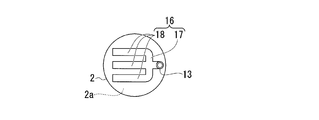
- FIG. 2 is a view taken along line AA in FIG. 1. It is a principal part top view of main piping. It is a principal part side view of main piping. It is a principal part top view which shows the modification of a distributor.
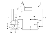
- FIG. 1 is a schematic configuration diagram schematically showing one embodiment of a low-temperature liquefied gas tank of the present invention.
- reference numeral 1 is a low-temperature liquefied gas tank
- 2 is a storage tank.
- the storage tank 2 stores LNG (Liquefied Natural Gas), LPG (Liquefied petroleum Gas), and low-temperature liquefied gas (low-temperature liquefied gas) such as methane, ethane, and propane.
- the storage tank 2 is a tank that stores LNG (liquefied natural gas) 3.
- the storage tank 2 includes, for example, a metal inner tank and a concrete outer tank.
- the inner tank is a container that directly stores liquefied gas
- the outer tank is a container that surrounds and stores the inner tank. Between these inner tank and outer tank, a cold insulating material, a liner, etc. are accommodated and a cold insulating layer is formed.
- the storage tank 2 having such a configuration is provided with an extraction pipe 4 for extracting the LNG 3 stored inside (inside the inner tank) to the outside.
- One end side of the extraction pipe 4 is disposed on the bottom 2a side in the storage tank 2, and the extraction pipe 4 extends through a roof portion 2b of the storage tank 2 to the outside and then extends to a header (not shown). It is installed.
- the header is connected to each extraction pipe (not shown) from other storage tanks (not shown) other than the storage tank 2, and the LNG extracted by each extraction pipe is transferred to a predetermined location. Is done.
- a reliquefaction facility 6 for reliquefying BOG (boil-off gas) generated in the storage tank 2 is connected to the storage tank 2 through a pipe 5.
- One end of the pipe 5 is connected to the roof portion 2 b of the storage tank 2, and the other end is connected to the reliquefaction facility 6.
- the pipe 5 feeds the BOG generated in the storage tank 2 and accumulated above the liquid level 3 a of the LNG 3 to the reliquefaction facility 6.
- the reliquefaction facility 6 includes a compressor 7 connected to the pipe 5 and a cooler 9 connected to the compressor 7 via the pipe 8.
- the compressor 7 is a compressor that compresses BOG to about 450 kPaA (4.58872 kg / cm 2 A), for example, and leads the compressed BOG to the cooler 9 through the pipe 8.
- the cooler 9 is configured in the same manner as in the prior art, and cools the BOG sent from the compressor 7 to a temperature at which the BOG is liquefied at that pressure, for example, about ⁇ 168 ° C., and liquefies (reliquefies) the compressed BOG.
- a gas-liquid separation drum 11 is connected to the cooler 9 via a pipe 10.
- the gas-liquid separation drum 11 is a device for gas-liquid separation of the re-liquefied BOG, and a pipe 12 for discharging the separated gas is connected to the top and a pipe for leading the separated liquid to the bottom. 13 is connected.
- the pipe 12 is provided with an on-off valve 14.
- the on-off valve 14 is always closed.
- a valve 15 is also provided in the pipe 13.
- the valve 15 is always open during the BOG reliquefaction process, and functions to reduce the pressure of the reliquefied BOG that has passed through the valve 15 to the pressure in the storage tank 2.
- the pipe 13 has a tip end side (a side opposite to the gas-liquid separation drum 11) disposed on the bottom 2 a side in the storage tank 2 through the roof portion 2 b of the storage tank 2.
- a distributor 16 is connected to the tip of the pipe 13.
- the distributor 16 is a tubular device arranged along the inner surface of the bottom 2a of the storage tank 2 on the bottom 2a side, that is, slightly above the inner surface. Accordingly, the distributor 16 is disposed sufficiently below the liquid level 3 a of the LNG 3 stored in the storage tank 2.
- the distributor 16 includes a branch pipe 17 connected to the pipe 13 and three main pipes connected to the branch pipe 17 as shown in FIG. 18.
- branch pipes 17 and main pipe 18 have their ends closed.
- the three main pipes 18 are arranged at the same level (height) so that the surfaces formed by the three main pipes 18 are parallel to the inner surface of the bottom 2a.
- these main pipes 18 are arranged at an appropriate interval from each other, so that the main pipes 18 are arranged almost uniformly over the entire inner surface of the bottom 2a without being biased.
- FIG. 2B which is the principal part top view
- FIG. 2C which is a principal part side view
- many horizontal positions of the both side surfaces facing in the horizontal direction are provided.
- a hole 18a is formed.
- These holes 18 a are formed in a circular shape having an inner diameter of, for example, several millimeters, and are formed and arranged at several tens to several hundreds at regular intervals along the length direction of the main pipe 18.
- the distributor 16 including the main pipe 18 and the branch pipe 17, the pipe 13, the gas-liquid separation drum 11, and the pipe 10 constitute a return means according to the present invention.
- the BOG re-liquefied by the re-liquefaction facility 6 that is, the re-liquefied BOG flows into the gas-liquid separation drum 11. .
- the gas component is not separated here and is pumped by the pressure of the compressor 7 in the reliquefaction facility 6. It flows into the storage tank 2 through the pipe 13 as it is.
- the nitrogen gas in the reliquefied BOG flows into the LNG 3 as fine bubbles, so that the LNG 3 is dissolved and absorbed in the LNG 3 while rising from the bottom 2a side to the liquid level 3a side. . Therefore, conventionally, the reliquefied BOG is returned to the space portion on the roof portion 2b side from the liquid level 3a of the LNG 3 in the storage tank 2, whereby the gasified (vaporized) nitrogen in the reliquefied BOG is accumulated in this space portion. While the concentration gradually increased, in the present embodiment, nitrogen in the reliquefied BOG is dissolved and absorbed in LNG 3 and hardly accumulates in the space.
- the nitrogen concentration in the space portion does not increase, and accordingly, the concentration of nitrogen contained in the BOG led out from the space portion to the reliquefaction facility 6 by the reliquefaction operation increases with the circulation by the reliquefaction operation. And is kept almost constant.
- the return means for returning the reliquefied BOG to the storage tank 2 is disposed below the liquid level 3a of the LNG 3 stored in the storage tank 2, and the reliquefied BOG. Is distributed in the LNG 3. For this reason, even if a part of the reliquefied BOG is vaporized, the reliquefied BOG is ejected into the LNG 3 by the distributor 16, so that the vaporized gas in the reliquefied BOG is dissolved and absorbed in the LNG3.
- nitrogen contained at a high concentration in the vaporized gas is also absorbed in LNG3. Therefore, this nitrogen is mixed with the BOG generated in the storage tank 2 and sent again to the reliquefaction facility 6 to prevent circulation. Therefore, it is prevented that the nitrogen concentration in BOG becomes high and BOG is not liquefied by the reliquefaction facility 6, and loss due to discarding the gas that is not liquefied can be reduced. Moreover, since it can suppress that the nitrogen concentration in BOG becomes high with a simple structure which only has the distributor 16, it can suppress the increase in manufacturing cost or operating cost.
- the distributor 16 has a main pipe 18 disposed along the inner surface of the bottom 2 a of the storage tank 2, and has a configuration in which a large number of holes 18 a are formed at positions facing the horizontal direction of the side surface of the main pipe 18. Yes. Therefore, the reliquefied BOG is ejected almost evenly from both sides of the main pipe 18, so that the nitrogen gas in the reliquefied BOG is evenly distributed on both sides of the main pipe 18. Therefore, since the nitrogen gas is ejected almost uniformly into the LNG 3, it is dissolved and absorbed well in the LNG 3, and the liquid level 3a is prevented from rising and collecting in the space.
- the three main pipes 18 are arranged at the same level, and are arranged almost uniformly over the entire inner surface of the bottom 2a. Therefore, the reliquefied BOG flows in a state of being well dispersed in almost the entire area in the storage tank 2, and therefore the nitrogen gas in the reliquefied BOG is dissolved and absorbed better in the LNG3.
- the present invention is not limited to the above-described embodiment, and various modifications can be made without departing from the gist of the present invention.
- the distributor 16 including the branch pipe 17 and the three main pipes 18 as shown in FIGS. 2A, 2B, and 2C is used as the distributor.
- the present invention is not limited to this. It is possible to use distributors having various shapes and configurations.
- a distributor having a configuration in which a plurality of branch pipes 19 are provided in the main pipe 18 and a plurality of holes 19a are formed in the branch pipes 19 can be used.
- the branch pipes 19 are provided on both sides of the main pipe 18 and on both sides in the horizontal direction.
- the branch pipes 19 are formed with a large number of holes 19a at the positions facing the horizontal direction on both side surfaces facing the horizontal direction.
- These holes 19a have a circular shape with an inner diameter of about several millimeters, for example, and are formed and arranged at several tens of intervals along the length direction of the branch pipe 19.
- the holes 19a for ejecting the reliquefied BOG can be arranged more widely and almost uniformly over the entire inner surface of the bottom 2a. Therefore, the reliquefied BOG can be more favorably dispersed in almost the entire area in the storage tank 2. Therefore, the nitrogen gas in the reliquefied BOG can be better dissolved and absorbed in LNG3.
- the number of the main pipes 18 is not limited to three, but can be an arbitrary number according to the area of the bottom 2a and the like.
- the large-diameter ring-shaped tube and the small-diameter ring-shaped tube are concentrically arranged, and are arranged more widely and substantially uniformly over the entire inner surface of the bottom portion 2a.
- the number of branch pipes 19 can be arbitrarily set.
- the present invention is applied to a low temperature liquefied gas tank for LNG.
- the present invention can also be applied to a tank for storing other low temperature liquefied gases such as LPG, methane, ethane, propane and the like.
- the present invention provides a low-temperature liquefied gas tank that suppresses an increase in nitrogen concentration in BOG with a simple apparatus configuration, thereby suppressing an increase in manufacturing cost and operating cost.
Landscapes
- Engineering & Computer Science (AREA)
- Mechanical Engineering (AREA)
- General Engineering & Computer Science (AREA)
- Chemical & Material Sciences (AREA)
- Chemical Kinetics & Catalysis (AREA)
- General Chemical & Material Sciences (AREA)
- Oil, Petroleum & Natural Gas (AREA)
- Physics & Mathematics (AREA)
- Thermal Sciences (AREA)
- Filling Or Discharging Of Gas Storage Vessels (AREA)
Abstract
本発明の低温液化ガスタンクは、低温液化ガス(3)を貯留する貯槽(2)と、貯槽(2)で発生したボイルオフガスを再液化する再液化設備(6)と、を備えた低温液化ガスタンク(1)である。再液化設備(6)で液化された再液化ボイルオフガスを貯槽(2)に返送する返送手段を有する。返送手段は、貯槽(2)に貯留された低温液化ガス(3)の液面(3a)より下方に配置されて、再液化ボイルオフガスを低温液化ガス(3)中に噴出するディストリビューター(16)を有している。
Description
本発明は、低温液化ガスタンクに関する。
本願は、2013年5月15日に日本に出願された特願2013-103287号に基づき優先権を主張し、その内容をここに援用する。
本願は、2013年5月15日に日本に出願された特願2013-103287号に基づき優先権を主張し、その内容をここに援用する。
従来、LNG(液化天然ガス)等の低温液化ガスを貯留する貯槽を備えた低温液化タンクでは、低温液化ガスが気化することで発生したボイルオフガス(以下、BOGと記す。)を再液化し、製品形態としての液化ガスに戻している。すなわち、発生したBOGを再液化設備で圧縮・冷却して再液化し、一旦気液分離ドラムで液化しなかった気体を分離した後、貯槽の上部に返送している(例えば、特許文献1参照)。
しかし、気液分離ドラムから液体のみを貯槽に返送しようとしても、再液化したBOGは貯槽の圧力まで減圧する際に液の一部が気化してしまう。ここで、低温液化ガス(例えばLNG)には窒素が混在していることから、低温液化ガスと窒素の沸点の違いにより、気化したガスには相対的に窒素が多く含まれる。つまり、貯槽に返送される気化ガスは窒素濃度が高くなる。このような窒素は、貯槽の上部、すなわち低温液化ガスの液面より上方に返送されることで、貯槽で発生するBOGと混合され、再度再液化設備に送られる。
このようにして再液化の循環が続けられると、BOG中の窒素濃度が徐々に高くなる。そして、窒素濃度がある濃度より高くなると、再液化設備でBOGが液化されない現象が起こる。
このようにBOGが液化されない現象が起こると、液化されないガスは気液分離ドラムで分離されてフレアなどに送られ、捨てられてしまうため、不経済となる。
このようにBOGが液化されない現象が起こると、液化されないガスは気液分離ドラムで分離されてフレアなどに送られ、捨てられてしまうため、不経済となる。
そこで、前記特許文献1では、BOGを冷却して得られた飽和状態にある液を、一旦気液分離した後に再度冷却し、過冷却状態にした上で貯槽に戻すようにしている。
しかしながら、このような気液分離後の液化ガスを再度冷却して過冷却状態にするのでは、装置が複雑になるとともに、エネルギーコストが増加するため、低温液化ガスタンクの製造コスト、運転コストが共に高くなる。
しかしながら、このような気液分離後の液化ガスを再度冷却して過冷却状態にするのでは、装置が複雑になるとともに、エネルギーコストが増加するため、低温液化ガスタンクの製造コスト、運転コストが共に高くなる。
本発明はこのような事情に鑑みてなされたもので、その目的とするところは、簡易な装置構成でBOG中の窒素濃度が高くなるのを抑制し、これによって製造コストや運転コストの増加を抑制した、低温液化ガスタンクを提供することにある。
本発明の低温液化ガスタンクは、低温液化ガスを貯留する貯槽と、前記貯槽で発生したボイルオフガスを再液化する再液化設備と、を備えた低温液化ガスタンクにおいて、前記再液化設備で液化された再液化ボイルオフガスを前記貯槽に返送する返送手段を有し、前記返送手段は、前記貯槽に貯留された低温液化ガスの液面より下方に配置されて、再液化ボイルオフガスを前記低温液化ガス中に噴出するディストリビューターを有している。
また、前記低温液化ガスタンクにおいて、前記ディストリビューターは、前記貯槽の底部内面に沿って配置された主配管を有し、前記主配管の側面の水平方向に向く位置に多数の孔が形成されて構成されていることが好ましい。
また、前記低温液化ガスタンクにおいて、前記ディストリビューターは、前記貯槽の底部内面に沿って配置された主配管と、前記主配管からその側方でかつ水平方向に向かって分岐した枝配管とを有し、前記枝配管の側面の水平方向に向く位置に多数の孔が形成されて構成されていることが好ましい。
本発明の低温液化ガスタンクによれば、再液化ボイルオフガスを貯槽に返送する返送手段が、貯槽に貯留された低温液化ガスの液面より下方に配置されて、再液化ボイルオフガスを前記低温液化ガス中に噴出するディストリビューターを有している。そのため、再液化ボイルオフガスが貯槽に返送される際に貯槽の圧力まで減圧されて液の一部が気化しても、この再液化ボイルオフガスがディストリビューターによって低温液化ガス中に噴出されるので、再液化ボイルオフガス中の気化ガスは低温液化ガス中に溶解して吸収される。したがって、気化ガス中に高濃度で含まれる窒素も低温液化ガス中に吸収されるため、貯槽で発生するボイルオフガスに混合されて再度再液化設備に送られ、循環させられることが防止される。よって、ボイルオフガス中の窒素濃度が高くなって再液化設備でボイルオフガスが液化されなくなるのを防止し、液化されないガスを捨てることによる損失を低減することができる。
また、単にディストリビューターを備えるだけの簡易な構成でボイルオフガス中の窒素濃度が高くなるのを抑制できるため、製造コストや運転コストの増加を抑制することができる。
また、単にディストリビューターを備えるだけの簡易な構成でボイルオフガス中の窒素濃度が高くなるのを抑制できるため、製造コストや運転コストの増加を抑制することができる。
以下、図面を参照して本発明の低温液化ガスタンクを詳しく説明する。なお、以下の図面においては、各部材を認識可能な大きさとするため、各部材の縮尺を適宜変更している。
図1は、本発明の低温液化ガスタンクの一実施形態を模式的に示す概略構成図であり、図1中符号1は低温液化ガスタンク、2は貯槽である。貯槽2は、LNG(Liquefied Natural Gas)やLPG(Liquefied petroleum Gas)、さらにはメタン、エタン、プロパン等の低温の液化ガス(低温液化ガス)を貯留するためである。本実施形態では、貯槽2はLNG(液化天然ガス)3を貯留するタンクとする。
図1は、本発明の低温液化ガスタンクの一実施形態を模式的に示す概略構成図であり、図1中符号1は低温液化ガスタンク、2は貯槽である。貯槽2は、LNG(Liquefied Natural Gas)やLPG(Liquefied petroleum Gas)、さらにはメタン、エタン、プロパン等の低温の液化ガス(低温液化ガス)を貯留するためである。本実施形態では、貯槽2はLNG(液化天然ガス)3を貯留するタンクとする。
貯槽2は、例えば金属製の内槽とコンクリート製の外槽とを備えて構成されている。内槽は、液化ガスを直接貯留する容器であり、外槽は、内槽を囲って収容する容器である。これら内槽と外槽との間には、保冷材やライナ等が収容されて保冷層が形成されている。
このような構成からなる貯槽2には、内部(内槽内)に貯留されたLNG3を外部に抜き出すための抜出配管4が設けられている。抜出配管4の一端側は貯槽2内の底部2a側に配置され、抜出配管4はこの貯槽2の屋根部2bを貫通して外部に引き出された後、図示しないヘッダにまで延びて配設されている。ヘッダには、貯槽2以外の他の貯槽(図示せず)からもそれぞれの抜出配管(図示せず)が接続されており、それぞれの抜出配管によって抜き出されたLNGが所定箇所に移送される。
また、貯槽2には、配管5を介して貯槽2で発生したBOG(ボイルオフガス)を再液化する再液化設備6が接続されている。配管5の一端は貯槽2の屋根部2bに接続され、他端が再液化設備6に接続されている。これによって配管5は、貯槽2内で発生し、LNG3の液面3aより上に溜まっているBOGを再液化設備6に送気する。
再液化設備6は、配管5に接続された圧縮機7と、圧縮機7に配管8を介して接続された冷却器9とを備えて構成されている。圧縮機7は、例えばBOGを450kPaA(4.58872kg/cm2A)程度に圧縮するコンプレッサであり、配管8を介して圧縮したBOGを冷却器9に導出する。
冷却器9は、従来と同様に構成され、圧縮機7から送られてきたBOGをその圧で液化する温度、例えば-168℃程度に冷却し、圧縮したBOGを液化(再液化)する。この冷却器9には、配管10を介して気液分離ドラム11が接続されている。
気液分離ドラム11は、再液化されたBOGを気液分離する装置であり、その頂部には分離されたガスを排出する配管12が接続され、底部には分離された液分を導出する配管13が接続されている。
気液分離ドラム11は、再液化されたBOGを気液分離する装置であり、その頂部には分離されたガスを排出する配管12が接続され、底部には分離された液分を導出する配管13が接続されている。
配管12には、開閉弁14が設けられている。ただし、本実施形態では、後述するように再液化設備6に送られたBOGは全量が再液化し、したがってBOG中の窒素も含めてほとんど気化していないため、気液分離ドラム11で分離されるガスもほとんどない。よって、開閉弁14は常時閉じられている。
配管13にも、弁15が設けられている。この弁15は、BOGの再液化処理を行っている間は常時開かれており、弁15を通過した再液化BOGの圧を、貯槽2内の圧力に下げるように機能している。また、配管13は、その先端側(気液分離ドラム11と反対の側)は、貯槽2の屋根部2bを通って貯槽2内の底部2a側に配置されている。この配管13の先端部にはディストリビューター16が接続されている。
ディストリビューター16は、貯槽2の底部2aの内面に沿って底部2a側、すなわちその内面より少し上方に配置された管状の装置である。これによってディストリビューター16は、貯槽2に貯留されたLNG3の液面3aより充分に下方に配置されている。本実施形態では、ディストリビューター16は、図1のA-A線矢視図である図2Aに示すように、配管13に接続する分岐管17と、この分岐管17に接続する3つの主配管18とを有して構成されている。
これら分岐管17、主配管18は、その先端が閉じられている。3つの主配管18は、互いに平行に配置され、かつこれら3つの主配管18が形成する面が、底部2aの内面に平行になるように、全て同じレベル(高さ)に配置されている。また、これらの主配管18は、互いに適宜な間隔で配置されることにより、偏ることなく、底部2aの内面の全域にほぼ均等に位置するように配置されている。
また、主配管18には、その要部平面図である図2B、および要部側面図である図2Cに示すように、その水平方向に向く両側の側面の水平方向に向く位置に、多数の孔18aが形成されている。これら孔18aは、例えば数mm程度の内径を有する円形状に形成され、主配管18の長さ方向に沿って等間隔で数十から数百個程度形成配置されている。
なお、このような主配管18および分岐管17を備えるディストリビューター16と、配管13、気液分離ドラム11、配管10により、本発明に係る返送手段が構成されている。
なお、このような主配管18および分岐管17を備えるディストリビューター16と、配管13、気液分離ドラム11、配管10により、本発明に係る返送手段が構成されている。
このような構成の低温液化ガスタンクでは、従来と同様にしてBOGの再液化運転を行うと、再液化設備6で再液化処理されたBOG、すなわち再液化BOGは、気液分離ドラム11に流入する。しかし、後述するように本実施形態では再液化設備6でBOGが液化されない現象が起こらないので、ここでガス分が分離されることなく、再液化設備6における圧縮機7による圧力で圧送されてそのまま配管13を通って貯槽2内に流入する。
その際、再液化BOGは、圧縮機7で圧縮された高圧状態から貯槽2内の相対的に低い圧に戻されるため、LNG3の主成分であるメタンに比べて沸点が低い窒素が先に気化し、再液化BOG中にて微小な気泡となる。そして、このような窒素ガスからなる気泡を有する再液化BOGは、配管13を通ってディストリビューター16に至り、その側面に形成された多数の孔18aからLNG3中に噴出される。
すると、再液化BOG中の窒素ガスは、微小な気泡のままLNG3中に流入することにより、LNG3中をその底部2a側から液面3a側に上昇する間にLNG3中に溶解し、吸収される。したがって、従来では貯槽2内のLNG3の液面3aより屋根部2b側の空間部に再液化BOGが返送され、これによって再液化BOG中のガス化(気化)した窒素がこの空間部に溜まって次第にその濃度が高くなっていたのに対し、本実施形態では再液化BOG中の窒素がLNG3中に溶解し吸収されるためほとんど前記空間部に溜まることがない。そのため、前記空間部での窒素濃度も高くなることがなく、したがって再液化運転によって前記空間部から再液化設備6に導出されたBOGに含まれる窒素の濃度が再液化運転による循環に伴って高くなることがなく、ほぼ一定に維持される。
このように本実施形態の低温液化ガスタンク1にあっては、再液化BOGを貯槽2に返送する返送手段が、貯槽2に貯留されたLNG3の液面3aより下方に配置されて、再液化BOGをLNG3中に噴出するディストリビューター16を有している。このため、再液化BOGの一部が気化しても、この再液化BOGがディストリビューター16によってLNG3中に噴出されるので、再液化BOG中の気化ガスはLNG3中に溶解して吸収される。
したがって、気化ガス中に高濃度で含まれる窒素もLNG3中に吸収される。そのため、この窒素が、貯槽2で発生するBOGに混合されて再度再液化設備6に送られ、循環することが防止される。よって、BOG中の窒素濃度が高くなって再液化設備6でBOGが液化されなくなることが防止され、液化されないガスを捨てることによる損失を低減することができる。
また、単にディストリビューター16を備えるだけの簡易な構成でBOG中の窒素濃度が高くなるのを抑制できるため、製造コストや運転コストの増加を抑制することができる。
また、単にディストリビューター16を備えるだけの簡易な構成でBOG中の窒素濃度が高くなるのを抑制できるため、製造コストや運転コストの増加を抑制することができる。
また、ディストリビューター16として、貯槽2の底部2a内面に沿って配置された主配管18を有し、主配管18の側面の水平方向に向く位置に多数の孔18aが形成された構成を用いている。そのため、再液化BOGが主配管18の両側からほぼ均等に噴出し、したがって再液化BOG中の窒素ガスも主配管18の両側に均等に分散する。よって、窒素ガスはLNG3中にほぼ均一に噴出するため、LNG3中に良好に溶解し吸収されるようになり、液面3aを上昇して前記空間部に溜まることが防止される。
また、3つの主配管18が同じレベルに配置するとともに、底部2aの内面の全域にほぼ均等に配置されている。そのため、再液化BOGは貯槽2内のほぼ全域により良好に分散した状態で流入するようになり、したがって再液化BOG中の窒素ガスはLNG3中により良好に溶解し吸収される。
なお、本発明は前記実施形態に限定されることなく、本発明の主旨を逸脱しない範囲で種々の変更が可能である。
例えば、前記実施形態ではディストリビューターとして、図2A、図2B、図2Cに示したように分岐管17と3つの主配管18とからなるディストリビューター16を用いたが、本発明はこれに限定されることなく、種々の形状・構成からなるディストリビューターを用いることができる。
例えば、前記実施形態ではディストリビューターとして、図2A、図2B、図2Cに示したように分岐管17と3つの主配管18とからなるディストリビューター16を用いたが、本発明はこれに限定されることなく、種々の形状・構成からなるディストリビューターを用いることができる。
例えば、図3に示すように主配管18に複数の枝配管19を設け、この枝配管19に多数の孔19aを形成した構成のディストリビューターを用いることもできる。枝配管19は、主配管18の側方でかつ水平方向に向かってその両側にそれぞれ分岐して設けられている。そして、これら枝配管19には、その水平方向に向く両側の側面の水平方向に向く位置に、多数の孔19aが形成されている。これら孔19aは、例えば数mm程度の内径に形成された円形状で、枝配管19の長さ方向に沿って等間隔で数十程度形成配置されている。
なお、この例でも主配管18に多数の孔18aを形成するのが好ましいが、図3に示すように孔18aを形成しない構造としてもよい。
なお、この例でも主配管18に多数の孔18aを形成するのが好ましいが、図3に示すように孔18aを形成しない構造としてもよい。
このような構成のディストリビューターを用いれば、再液化BOGを噴出するための孔19aを底部2aの内面の全域により広くかつほぼ均等に配置できる。そのため、再液化BOGを貯槽2内のほぼ全域により良好に分散させることができる。したがって、再液化BOG中の窒素ガスをLNG3中により良好に溶解させ、吸収させることができる。
また、本発明に係るディストリビューターとしては、例えば主配管18の数も3つに限定されることなく、底部2aの面積等に応じて任意の数にすることができる。また、その形状についても、直管でなく、例えば貯槽2の側壁内面に沿うリング状(円環状)の管によって形成してもよい。その場合に、大径のリング状管と小径のリング状管とを同心状に配置し、底部2aの内面の全域により広くかつほぼ均等に配置するのが好ましい。
さらに、枝配管19についても、その数等については任意に設定することができる。
また、前記実施形態では本発明をLNG用の低温液化ガスタンクに適用したが、本発明はLPGやメタン、エタン、プロパン等のその他の低温液化ガスを貯留するためのタンクにも適用可能である。
また、前記実施形態では本発明をLNG用の低温液化ガスタンクに適用したが、本発明はLPGやメタン、エタン、プロパン等のその他の低温液化ガスを貯留するためのタンクにも適用可能である。
本発明は、簡易な装置構成でBOG中の窒素濃度が高くなるのを抑制し、これによって製造コストや運転コストの増加を抑制した、低温液化ガスタンクを提供する。
1…低温液化ガスタンク
2…貯槽
2a…底部
2b…屋根部
3…LNG(低温液化ガス)
3a…液面
6…再液化設備
7…圧縮機
9…冷却機、
16…ディストリビューター
18…主配管
18a…孔
19…枝配管
19a…孔
2…貯槽
2a…底部
2b…屋根部
3…LNG(低温液化ガス)
3a…液面
6…再液化設備
7…圧縮機
9…冷却機、
16…ディストリビューター
18…主配管
18a…孔
19…枝配管
19a…孔
Claims (3)
- 低温液化ガスを貯留する貯槽と、前記貯槽で発生したボイルオフガスを再液化する再液化設備と、を備えた低温液化ガスタンクにおいて、
前記再液化設備で液化された再液化ボイルオフガスを前記貯槽に返送する返送手段を有し、
前記返送手段は、前記貯槽に貯留された低温液化ガスの液面より下方に配置されて、再液化ボイルオフガスを前記低温液化ガス中に噴出するディストリビューターを有している低温液化ガスタンク。 - 前記ディストリビューターは、前記貯槽の底部内面に沿って配置された主配管を有し、前記主配管の側面の水平方向に向く位置に多数の孔が形成されて構成されている請求項1記載の低温液化ガスタンク。
- 前記ディストリビューターは、前記貯槽の底部内面に沿って配置された主配管と、前記主配管からその側方でかつ水平方向に向かって分岐した枝配管とを有し、前記枝配管の側面の水平方向に向く位置に多数の孔が形成されて構成されている請求項1記載の低温液化ガスタンク。
Priority Applications (2)
| Application Number | Priority Date | Filing Date | Title |
|---|---|---|---|
| CN201480026569.3A CN105164462A (zh) | 2013-05-15 | 2014-04-24 | 低温液化气罐 |
| US14/849,713 US20150377550A1 (en) | 2013-05-15 | 2015-09-10 | Low-temperature liquefied gas tank |
Applications Claiming Priority (2)
| Application Number | Priority Date | Filing Date | Title |
|---|---|---|---|
| JP2013103287A JP2014224553A (ja) | 2013-05-15 | 2013-05-15 | 低温液化ガスタンク |
| JP2013-103287 | 2013-05-15 |
Related Child Applications (1)
| Application Number | Title | Priority Date | Filing Date |
|---|---|---|---|
| US14/849,713 Continuation US20150377550A1 (en) | 2013-05-15 | 2015-09-10 | Low-temperature liquefied gas tank |
Publications (1)
| Publication Number | Publication Date |
|---|---|
| WO2014185248A1 true WO2014185248A1 (ja) | 2014-11-20 |
Family
ID=51898228
Family Applications (1)
| Application Number | Title | Priority Date | Filing Date |
|---|---|---|---|
| PCT/JP2014/061590 Ceased WO2014185248A1 (ja) | 2013-05-15 | 2014-04-24 | 低温液化ガスタンク |
Country Status (4)
| Country | Link |
|---|---|
| US (1) | US20150377550A1 (ja) |
| JP (1) | JP2014224553A (ja) |
| CN (1) | CN105164462A (ja) |
| WO (1) | WO2014185248A1 (ja) |
Cited By (1)
| Publication number | Priority date | Publication date | Assignee | Title |
|---|---|---|---|---|
| CN105387683A (zh) * | 2015-12-21 | 2016-03-09 | 刘印同 | 天然气高效液化回收方法及装置 |
Families Citing this family (7)
| Publication number | Priority date | Publication date | Assignee | Title |
|---|---|---|---|---|
| JP6155758B2 (ja) | 2013-03-29 | 2017-07-05 | 株式会社Ihi | 低温液体タンク |
| JP6036605B2 (ja) | 2013-08-23 | 2016-11-30 | 株式会社Ihi | 地上式低温タンク |
| NL2016938B1 (en) * | 2016-06-10 | 2018-01-25 | Liqal B V | Method and system for at least partially converting methane-containing gas, in particular boil-off gas, retained in a container, to a liquid state |
| FR3060708B1 (fr) * | 2016-12-21 | 2019-10-25 | Engie | Dispositif, systeme et procede de regulation de la pression pour un reservoir de stockage de gaz naturel liquefie |
| FR3060707A1 (fr) | 2016-12-21 | 2018-06-22 | Engie | Dispositif, systeme et procede de regulation de la pression pour un reservoir de stockage de gaz naturel liquefie |
| FR3066248B1 (fr) * | 2017-05-12 | 2020-12-11 | Gaztransport Et Technigaz | Procede et systeme de traitement de gaz d'une installation de stockage de gaz pour un navire de transport de gaz |
| CN107228274A (zh) * | 2017-06-02 | 2017-10-03 | 浙江大学 | 固定式多层真空绝热高压液氢储罐 |
Citations (3)
| Publication number | Priority date | Publication date | Assignee | Title |
|---|---|---|---|---|
| US3213632A (en) * | 1960-03-07 | 1965-10-26 | California Texas Oil Corp | Ship for transporting liquefied gases and other liquids |
| US4188796A (en) * | 1976-10-15 | 1980-02-19 | Linde Aktiengesellschaft | Method of and apparatus for the cooling (quenching) of cracking gases |
| JPH1163396A (ja) * | 1997-08-18 | 1999-03-05 | Ishikawajima Harima Heavy Ind Co Ltd | ボイルオフガスの凝縮装置および液化ガス貯蔵設備 |
Family Cites Families (5)
| Publication number | Priority date | Publication date | Assignee | Title |
|---|---|---|---|---|
| JP2000046295A (ja) * | 1998-07-27 | 2000-02-18 | Ishikawajima Harima Heavy Ind Co Ltd | 低温液化ガスタンク内のbog再液化装置 |
| JP3716963B2 (ja) * | 1998-10-29 | 2005-11-16 | 株式会社サンセイアールアンドディ | パチンコ遊技機 |
| JP5148319B2 (ja) * | 2008-02-27 | 2013-02-20 | 三菱重工業株式会社 | 液化ガス再液化装置、これを備えた液化ガス貯蔵設備および液化ガス運搬船、並びに液化ガス再液化方法 |
| NO332551B1 (no) * | 2009-06-30 | 2012-10-22 | Hamworthy Gas Systems As | Fremgangsmate og anordning for lagring og transport av flytendegjort petroleumsgass |
| JP5715479B2 (ja) * | 2011-05-02 | 2015-05-07 | ジャパンマリンユナイテッド株式会社 | ボイルオフガス処理装置及び液化ガスタンク |
-
2013
- 2013-05-15 JP JP2013103287A patent/JP2014224553A/ja active Pending
-
2014
- 2014-04-24 WO PCT/JP2014/061590 patent/WO2014185248A1/ja not_active Ceased
- 2014-04-24 CN CN201480026569.3A patent/CN105164462A/zh active Pending
-
2015
- 2015-09-10 US US14/849,713 patent/US20150377550A1/en not_active Abandoned
Patent Citations (3)
| Publication number | Priority date | Publication date | Assignee | Title |
|---|---|---|---|---|
| US3213632A (en) * | 1960-03-07 | 1965-10-26 | California Texas Oil Corp | Ship for transporting liquefied gases and other liquids |
| US4188796A (en) * | 1976-10-15 | 1980-02-19 | Linde Aktiengesellschaft | Method of and apparatus for the cooling (quenching) of cracking gases |
| JPH1163396A (ja) * | 1997-08-18 | 1999-03-05 | Ishikawajima Harima Heavy Ind Co Ltd | ボイルオフガスの凝縮装置および液化ガス貯蔵設備 |
Cited By (1)
| Publication number | Priority date | Publication date | Assignee | Title |
|---|---|---|---|---|
| CN105387683A (zh) * | 2015-12-21 | 2016-03-09 | 刘印同 | 天然气高效液化回收方法及装置 |
Also Published As
| Publication number | Publication date |
|---|---|
| CN105164462A (zh) | 2015-12-16 |
| US20150377550A1 (en) | 2015-12-31 |
| JP2014224553A (ja) | 2014-12-04 |
Similar Documents
| Publication | Publication Date | Title |
|---|---|---|
| WO2014185248A1 (ja) | 低温液化ガスタンク | |
| KR102649053B1 (ko) | 액화 가스 및/또는 액화 가스로부터 나오는 자연 증발 가스를 냉각시키는 장치 및 방법 | |
| CA2832716C (en) | Boil-off gas processing apparatus and liquefied gas tank | |
| KR102295430B1 (ko) | 재액화 시스템 | |
| RU2628337C2 (ru) | Способы хранения криогенных текучих сред в резервуарах для хранения | |
| JP2009030675A (ja) | ガス再液化装置およびガス再液化方法 | |
| RU2014132457A (ru) | Способ повторного ожижения отпарного газа, образующегося в резервуарах для хранения жидкого водорода | |
| KR102590259B1 (ko) | 액화 가스 및/또는 액화 가스의 자연 증발 가스를 냉각시키는 장치 및 방법 | |
| KR20160087117A (ko) | 재액화 시스템 | |
| JP2016148001A (ja) | 液化ガス出荷設備向け熱量調整システム | |
| US20080184735A1 (en) | Refrigerant storage in lng production | |
| KR20170031429A (ko) | 연료가스 공급시스템 | |
| KR101517442B1 (ko) | 극저온 시험 장치 | |
| KR101741756B1 (ko) | 재액화 시스템 | |
| KR20170091378A (ko) | 가스 벙커링 라인 및 이를 포함하는 가스 벙커링 시스템 | |
| KR101732551B1 (ko) | 연료가스 공급시스템 | |
| KR20160071638A (ko) | 재액화 시스템 및 연료가스 공급시스템 | |
| KR20120128968A (ko) | 원유 운반선의 휘발성 유기 화합물 배출 감소 장치 | |
| ES2931401T3 (es) | Método y sistema para convertir al menos parcialmente gas que contiene metano, en particular gas de ebullición, retenido en un contenedor, a estado líquido | |
| KR101680336B1 (ko) | 재액화 설비를 구비하는 액화가스 탱크 | |
| KR102173909B1 (ko) | 연료공급시스템 | |
| KR101644389B1 (ko) | 연료가스 공급시스템 | |
| KR101309628B1 (ko) | 중질탄화수소의 분리를 위한 격벽이 설치된 액화천연가스 연료공급 시스템 | |
| KR101275038B1 (ko) | 필링 파이프가 내장되는 엘엔지 탱크 | |
| KR20170065292A (ko) | Bog 저감용 액체화물 저장탱크 |
Legal Events
| Date | Code | Title | Description |
|---|---|---|---|
| WWE | Wipo information: entry into national phase |
Ref document number: 201480026569.3 Country of ref document: CN |
|
| 121 | Ep: the epo has been informed by wipo that ep was designated in this application |
Ref document number: 14798253 Country of ref document: EP Kind code of ref document: A1 |
|
| NENP | Non-entry into the national phase |
Ref country code: DE |
|
| 122 | Ep: pct application non-entry in european phase |
Ref document number: 14798253 Country of ref document: EP Kind code of ref document: A1 |