WO2014181795A1 - ワイヤハーネスのシールド構造 - Google Patents
ワイヤハーネスのシールド構造 Download PDFInfo
- Publication number
- WO2014181795A1 WO2014181795A1 PCT/JP2014/062248 JP2014062248W WO2014181795A1 WO 2014181795 A1 WO2014181795 A1 WO 2014181795A1 JP 2014062248 W JP2014062248 W JP 2014062248W WO 2014181795 A1 WO2014181795 A1 WO 2014181795A1
- Authority
- WO
- WIPO (PCT)
- Prior art keywords
- shield
- shield wall
- wire harness
- resin mold
- wall
- Prior art date
- Legal status (The legal status is an assumption and is not a legal conclusion. Google has not performed a legal analysis and makes no representation as to the accuracy of the status listed.)
- Ceased
Links
Images

Classifications
-
- H—ELECTRICITY
- H02—GENERATION; CONVERSION OR DISTRIBUTION OF ELECTRIC POWER
- H02G—INSTALLATION OF ELECTRIC CABLES OR LINES, OR OF COMBINED OPTICAL AND ELECTRIC CABLES OR LINES
- H02G3/00—Installations of electric cables or lines or protective tubing therefor in or on buildings, equivalent structures or vehicles
- H02G3/22—Installations of cables or lines through walls, floors or ceilings, e.g. into buildings
-
- H—ELECTRICITY
- H05—ELECTRIC TECHNIQUES NOT OTHERWISE PROVIDED FOR
- H05K—PRINTED CIRCUITS; CASINGS OR CONSTRUCTIONAL DETAILS OF ELECTRIC APPARATUS; MANUFACTURE OF ASSEMBLAGES OF ELECTRICAL COMPONENTS
- H05K9/00—Screening of apparatus or components against electric or magnetic fields
- H05K9/0007—Casings
- H05K9/0018—Casings with provisions to reduce aperture leakages in walls, e.g. terminals, connectors, cables
Definitions
- the present invention relates to a shield structure when a wire harness is introduced into a shield wall (in a shield case) of an electric device.
- a metal shield shell is provided so as to surround the connector provided at the end portion of the electric wire, and a shield member (such as a braid) on the electric wire side is provided in the shield shell.
- a shield member such as a braid
- Patent Document 1 a shield layer is coated so as to cover the outer periphery of the electric wire, and on the other hand, a conductive rubber seal member is attached to the shield shell fixed to the shield wall of the shield case, and the end portion of the electric wire is sealed.
- a structure is disclosed in which a wire is inserted through a wire insertion hole of a member to a position where a shield layer is present and introduced into a shield wall. And the shield layer of an electric wire is made to conduct
- an object of the present invention is to provide a simple wire harness shield structure in which the number of parts is reduced in order to solve the above problems.
- the electric wire includes a conductor, an insulating resin mold portion that covers an outer periphery of the conductor, and a shield layer that covers an outer peripheral surface of the resin mold portion, and the shield layer is a predetermined in the length direction of the conductor.
- the resin mold part is integrally formed with a flange part fixed in close contact with the shield wall,
- the shield layer is formed so as to cover an outer surface of the flange portion,
- the shield layer coated on the electric wire is directly conducted to the shield wall, so that unnecessary conduction parts (conductive rubber seal, shield shell, etc.) for connecting the shield layer and the shield wall are unnecessary.
- the number of parts can be reduced and a simple shield structure can be realized.
- the shield layer is formed on the surface of the flange portion by coating, the adhesion surface of the flange portion to the shield wall can be formed flat. Therefore, compared with the case where the net-like shield member braided with a conductor such as a braid is brought into contact with the counterpart member to obtain conduction, a large contact surface can be secured and a stable conduction state can be obtained.
- the shield structure having the configuration (2) it is possible to ensure waterproofness and oilproofness. At that time, since the shield layer is directly connected to the shield wall, it is not necessary to provide conductivity to the waterproof / oilproof packing itself.
- the shield layer formed on the flange portion can be conducted to the shield wall by fixing the flange portion and the shield wall with the fastening portion.
- the present invention there is no need for an additional conductive component for connecting the shield layer coated on the electric wire and the shield wall of the electric device, the number of components can be reduced, and a simple shield structure can be realized. .
- FIG. 1 is a perspective view of a shield structure according to an embodiment of the present invention.
- 2A is a cross-sectional view of the shield structure of FIG. 1
- FIG. 2B is a partially enlarged view of FIG. 2A
- FIG. 1 is a perspective view of a shield structure according to an embodiment of the present invention.
- 2A is a cross-sectional view of the shield structure of FIG. 1
- FIG. 2B is a partially enlarged view of FIG. 2A
- FIG. 1 is a perspective view of a shield structure according to an embodiment of the present invention.
- 2A is a cross-sectional view of the shield structure of FIG. 1
- FIG. 2B is a partially enlarged view of FIG. 2A
- FIG. 1 is a perspective view of the shield structure of the embodiment
- FIG. 2A is a cross-sectional view of the shield structure of FIG. 1
- FIG. 2B is a partially enlarged view of FIG.
- this shield structure is configured such that the wire harness W is passed through a through hole 52 formed in the shield wall 50 into the interior 51 of the shield wall 50 of the electrical device.
- This is a shield structure when the electric wire 1 to be configured is introduced while being shielded and sealed.
- the electric wire 1 has a plurality of strip-like conductors 2 arranged at intervals in the thickness direction, and an insulating property that integrally surrounds and holds the plurality of conductors 2 in an insulated state. It has the resin mold part 3 and the shield layer 4 coated so that the outer peripheral surface of the resin mold part 3 might be covered.
- the resin mold part 3 is produced by setting the conductor 2 in a resin molding die and insert molding.
- the shield layer 4 is formed by resin plating (plating of a metal material on the surface of the resin) or conductive coating (coating of a conductive material), and a predetermined range in the length direction of the conductor 2 (range indicated by H1 in the figure). ).
- the electric wire 1 includes a flange portion 13 in front of a position where the electric wire 1 is inserted into the through hole 52 of the shield wall 50.
- the flange portion 13 is fixed in a state where the lower surface 13 b is in close contact with the upper surface 53 a of the mounting seat 53 of the shield wall 50.
- the flange portion 13 is formed integrally with the resin mold portion 3 when the resin mold portion 3 is molded.
- On the outer peripheral portion of the flange portion 13, a screw fastening portion 13 t for screw fixing to a screw fastening portion 53 t provided on the mounting seat 53 of the shield wall 50 is provided.
- the flange portion 13 is attached to the shield wall 50 in a state where the lower surface 13b of the flange portion 13 is in close contact with the upper surface 53a of the mounting seat 53 of the shield wall 50. It can be fixed.
- the shield layer 4 by coating provided as the outermost layer of the electric wire 1 is formed to extend to a position covering the outer surface of the flange portion 13. That is, when the shield layer covering the surface of the flange portion 13 is denoted by reference numeral 14, the shield layer 14 covers the entire surface of the upper surface 13a, the lower surface 13b, and the outer peripheral surface 13c of the flange portion 13 including the screw fastening portion 13t. It is coated to cover.
- a non-shield portion H ⁇ b> 2 obtained by removing the coating of the shield layer 4 over a predetermined range from the end portion of the conductor 2 of the electric wire 1 is secured at the terminal portion introduced into the shield wall 50.
- a terminal 2a as a conductor exposed portion where the conductor 2 is exposed by removing the resin mold is provided at an end portion of the portion H2 or a predetermined position near the end portion.
- the electric wire 1 is provided with an annular convex portion 23 in contact with the inner periphery of the through hole 52 on the outer periphery of the resin mold portion 3 of the terminal portion that is passed through the through hole 52 of the shield wall 50 on the lower side of the flange portion 13. It has been.
- a packing 18 that seals the gap between the outer periphery of the resin mold portion 3 and the inner periphery of the through hole 52 is attached to the outer periphery of the resin mold portion 3 between the annular convex portion 23 and the flange portion 13.
- the thus configured wire harness W introduces the terminal portion of the electric wire 1 through the through hole 52 into the inside 51 of the shield wall 50 and fixes the flange portion 13 in close contact with the mounting seat 53 of the shield wall 50.
- the shield layer 4 of the electric wire 1 is directly conducted to the shield wall 50 through the shield layer 14 of the flange portion 13.
- the shield layer 14 is formed on the surface of the flange portion 13 by coating, the adhesion surface of the flange portion 13 to the shield wall 50 can be formed flat. Therefore, compared with the case where the net-like shield member braided with a conductor such as a braid is brought into contact with the counterpart member to obtain conduction, a large contact surface can be secured and a stable conduction state can be obtained. Further, the shield layer 14 formed on the flange portion 13 can be electrically connected to the shield wall 50 simply by fixing the flange portion 13 and the shield wall 50 with the screw fastening portions 13t and 53t. Is easy.
- the packing 18 that seals the gap between the outer periphery of the resin mold portion 3 and the inner periphery of the through hole 52 is provided.
- the waterproof / oilproof property can be ensured.
- the shield layers 4 and 14 are directly connected to the shield wall 50, the waterproof / oilproof packing 18 itself does not need to have conductivity.
- the packing 18 for ensuring the sealing performance is provided in the introduction portion of the electric wire 1 with respect to the shield wall 50 in the introduction portion of the electric wire 1 with respect to the shield wall 50 in the above embodiment.
- a sealing material such as a curable resin is used instead of the packing. You may inject
- the electric wire (1) constituting the wire harness (W) is shielded in the inside (51) of the shield wall (50) in the through hole (52) formed in the shield wall (50) of the electric device.
- a shield structure for the inserted wire harness, The electric wire (1) includes a conductor (2), an insulating resin mold part (3) covering the outer periphery of the conductor (2), and a shield layer (4) covering the outer peripheral surface of the resin mold part (3).
- the shield layer (4) covers the resin mold part over a predetermined range in the length direction of the conductor (2),
- the resin mold part (3) is integrally formed with a flange part (13) fixed in close contact with the shield wall (50),
- the shield layer (4, 14) is formed so as to cover the outer surface (13a, 13b, 13c) of the flange portion (13),
- a packing (18) is inserted between the outer periphery of the resin mold part (3) and the inner periphery of the through hole (52) in the through hole (52).
- the shield structure for a wire harness according to the above [1].
- the shield wall (50) and the flange portion (13) are provided with fastening portions (53t, 13t) for fixing the flange portion (13) to the shield wall (50).
- the shield structure for a wire harness according to [1] or [2].
- the present invention there is no need for an additional conductive component for connecting a shield layer coated on an electric wire and a shield wall of an electric device, the number of components can be reduced, and a simple shield structure can be realized. Play.
- the present invention that exhibits this effect is useful for a shield structure when a wire harness is introduced into a shield wall (in a shield case) of an electric device.
Landscapes
- Engineering & Computer Science (AREA)
- Architecture (AREA)
- Civil Engineering (AREA)
- Structural Engineering (AREA)
- Insulated Conductors (AREA)
- Microelectronics & Electronic Packaging (AREA)
- Shielding Devices Or Components To Electric Or Magnetic Fields (AREA)
- Installation Of Indoor Wiring (AREA)
Abstract
シールド壁(50)に形成された貫通孔(52)を通して、シールド壁(50)の内部(51)にワイヤハーネス(W)を構成する電線(1)をシールドしながら導入するワイヤハーネスのシールド構造において、電線(1)が、導体(2)の外周を覆う絶縁性の樹脂モールド部(3)と、樹脂モールド部(3)の外周面をコーティングするシールド層(4)とを有し、樹脂モールド部(3)に、シールド壁(50)に対して密着した状態で固定されるフランジ部(13)が一体に形成され、フランジ部(13)の外表面(13a、13b、13c)を覆う位置まで、コーティングによるシールド層(4、14)が形成され、フランジ部(13)がシールド壁(50)に密着した状態で固定される。
Description
本発明は、ワイヤハーネスを電気機器のシールド壁内(シールドケース内)に導入する場合のシールド構造に関するものである。
従来、電線の端末部をシールドケース内にシールドしながら導入する場合、電線の端末部に設けたコネクタを囲むように金属製のシールドシェルを設け、そのシールドシェルに電線側のシールド部材(編組など)を接続した上で、シールドシェルをシールドケースのシールド壁に固定する構造が一般的に採用されていた。
しかし、この構造の場合、シールドシェルに電線側のシールド部材(主に編組)を接続するという面倒な作業が必要であった。そこで、特許文献1に、電線の外周を覆うようにシールド層をコーティングし、一方、シールドケースのシールド壁に固定されるシールドシェルに導電ゴム製のシール部材を装着し、電線の端末部をシール部材の電線挿通孔にシールド層のある位置まで挿通させてシールド壁内に導入する構造が開示されている。そして、導電ゴム製のシール部材及びシールドシェルを介して、電線のシールド層をシールド壁に導通させるようになっている。この構造によれば、シールドシェルに装着した導電ゴム製のシール部材の電線挿通孔に電線の端末部を挿通させるだけでシールド性能を確保できるので、装着が簡単にできる利点が得られる。
しかし、特許文献1に記載のシールド構造では、電線側のシールド層と電気機器のシールド壁とを導通させる部品として、導電ゴム製のシール部材を用いる必要があるので、部品点数が多くなってしまうという問題があった。
そこで、本発明の目的は、上記課題を解消することに係り、部品点数を削減した簡略なワイヤハーネスのシールド構造を提供することにある。
本発明の上記目的は、下記の構成により達成される。
(1) 電気機器のシールド壁に形成された貫通孔に、前記シールド壁の内部にワイヤハーネスを構成する電線がシールドされながら挿入されたワイヤハーネスのシールド構造であって、
前記電線が、導体と、前記導体の外周を覆う絶縁性の樹脂モールド部と、該樹脂モールド部の外周面を覆うシールド層とを有し、前記シールド層が、前記導体の長さ方向の所定範囲にわたり前記樹脂モールド部を覆い、
前記樹脂モールド部に、前記シールド壁に対して密着した状態で固定されるフランジ部が一体に形成され、
前記シールド層は、前記フランジ部の外表面を覆うように形成され、
前記フランジ部が前記シールド壁に密着した状態で固定されることにより、前記シールド層が前記シールド壁に直接導通されるワイヤハーネスのシールド構造。
(1) 電気機器のシールド壁に形成された貫通孔に、前記シールド壁の内部にワイヤハーネスを構成する電線がシールドされながら挿入されたワイヤハーネスのシールド構造であって、
前記電線が、導体と、前記導体の外周を覆う絶縁性の樹脂モールド部と、該樹脂モールド部の外周面を覆うシールド層とを有し、前記シールド層が、前記導体の長さ方向の所定範囲にわたり前記樹脂モールド部を覆い、
前記樹脂モールド部に、前記シールド壁に対して密着した状態で固定されるフランジ部が一体に形成され、
前記シールド層は、前記フランジ部の外表面を覆うように形成され、
前記フランジ部が前記シールド壁に密着した状態で固定されることにより、前記シールド層が前記シールド壁に直接導通されるワイヤハーネスのシールド構造。
(2) 前記貫通孔内における前記樹脂モールド部の外周と前記貫通孔の内周との間に、それらの間の隙間をシールするパッキンが挿入されている上記(1)に記載のワイヤハーネスのシールド構造。
(3) 前記シールド壁と前記フランジ部とに、前記フランジ部を前記シールド壁に固定するための締結部が設けられている上記(1)又は(2)に記載のワイヤハーネスのシールド構造。
上記(1)の構成のシールド構造によれば、電線にコーティングしたシールド層を直接シールド壁に導通させるので、シールド層とシールド壁を接続する余計な導通部品(導電ゴムシールやシールドシェル等)が不要であり、部品点数を削減することができて、簡略なシールド構造を実現できる。また、コーティングによりフランジ部の表面にシールド層を形成しているため、フランジ部のシールド壁に対する密着面を平坦に形成することができる。従って、編組などの導体を編んだ網状のシールド部材を相手側部材に接触させて導通を得る場合と比べて、接触面を大きく確保することができ、安定した導通状態を得ることができる。
上記(2)の構成のシールド構造によれば、防水・防油性を確保することができる。その際、シールド層が直接シールド壁に導通しているので、防水・防油パッキン自体に導電性を持たせる必要はなくなる。
上記(3)の構成のシールド構造によれば、フランジ部とシールド壁を締結部で固定することにより、フランジ部に形成してあるシールド層をシールド壁に導通させることができる。
本発明によれば、電線にコーティングしたシールド層と電気機器のシールド壁を接続するための追加的な導通部品が不要であり、部品点数を削減することができて、簡略なシールド構造を実現できる。
以上、本発明について簡潔に説明した。更に、以下に説明される発明を実施するための形態(以下、「実施形態」という。)を添付の図面を参照して通読することにより、本発明の詳細は更に明確化されるであろう。
以下、本発明の実施形態を図面を参照して説明する。
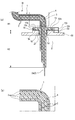
図1は実施形態のシールド構造の斜視図、図2(a)は図1のシールド構造の断面図、図2(b)は、図2(a)の部分拡大図である。
図1は実施形態のシールド構造の斜視図、図2(a)は図1のシールド構造の断面図、図2(b)は、図2(a)の部分拡大図である。
図1、図2(a)及び図2(b)に示すように、このシールド構造は、電気機器のシールド壁50の内部51に、シールド壁50に形成した貫通孔52を通して、ワイヤハーネスWを構成する電線1を、シールド及びシールしながら導入する場合のシールド構造である。まず、電線1は、厚さ方向に間隔をおいて配置された帯板状の複数枚の導体2と、これら複数枚の導体2を互いに絶縁した状態で一体的に包囲し保持する絶縁性の樹脂モールド部3と、樹脂モールド部3の外周面を覆うようにコーティングされたシールド層4と、を有している。
樹脂モールド部3は、樹脂成形用金型に導体2をセットし、インサート成形により作製される。また、シールド層4は、樹脂メッキ(樹脂の表面に対する金属材料のメッキ)や導電塗装(導電材料の塗装)により形成されており、導体2の長さ方向の所定範囲(図中H1で示す範囲)にわたり設けられている。
電線1は、シールド壁50の貫通孔52内に挿入される位置の手前に、フランジ部13を備えている。フランジ部13は、シールド壁50の取付座53の上面53aに対して下面13bを密着させた状態で固定される。フランジ部13は、樹脂モールド部3の成形時に樹脂モールド部3と一体に形成されている。フランジ部13の外周部には、シールド壁50の取付座53に設けたねじ締結部53tに対してねじ固定するためのねじ締結部13tが設けられている。これらのねじ締結部53t、13tを図示しないねじで締め付けることにより、フランジ部13の下面13bをシールド壁50の取付座53の上面53aに強く密着させた状態で、フランジ部13をシールド壁50に固定することができるようになっている。
電線1の最外層として設けられたコーティングによるシールド層4は、フランジ部13の外表面を覆う位置まで延長して形成されている。即ち、フランジ部13の表面を覆うシールド層を符号14で示すと、このシールド層14は、ねじ締結部13tを含めたフランジ部13の上面13aと、下面13bと、外周面13cの全表面を覆うようにコーティングされている。
電線1において、シールド壁50内に導入される端末部には、電線1の導体2の端部から所定範囲にわたりシールド層4のコーティングを除去した非シールド部H2が確保されており、その非シールド部H2の端部や端部に近い所定位置には、樹脂モールドを除去して導体2を露出させた導体露出部としての端子2aが設けられている。
また、電線1は、フランジ部13の下側において、シールド壁50の貫通孔52に通される端末部の樹脂モールド部3の外周に、貫通孔52の内周に接する環状凸部23が設けられている。環状凸部23とフランジ部13との間の樹脂モールド部3の外周には、樹脂モールド部3の外周と貫通孔52の内周との間の隙間をシールするパッキン18が装着されている。
このように構成されたワイヤハーネスWは、シールド壁50の内部51に貫通孔52を通して電線1の端末部を導入し、フランジ部13をシールド壁50の取付座53に密着した状態で固定することにより、フランジ部13のシールド層14を介して、電線1のシールド層4がシールド壁50に直接導通される。
従って、シールド層4とシールド壁50を接続する余計な導通部品(導電ゴムシールやシールドシェル等)が不要であり、部品点数を削減することができて、簡略なシールド構造を実現できる。また、コーティングによりフランジ部13の表面にシールド層14を形成しているため、フランジ部13のシールド壁50に対する密着面を平坦に形成することができる。従って、編組などの導体を編んだ網状のシールド部材を相手側部材に接触させて導通を得る場合と比べて、接触面を大きく確保することができ、安定した導通状態を得ることができる。また、フランジ部13とシールド壁50をねじ締結部13t、53tで固定するだけで、フランジ部13に形成してあるシールド層14をシールド壁50に導通させることができるので、シールド性確保のための作業が容易である。
また、本実施形態のシールド構造によれば、樹脂モールド部3の外周と貫通孔52の内周との間の隙間をシールするパッキン18を設けているので、シールド壁50に対する電線1の導入部における防水・防油性を確保することができる。その際、シールド層4、14が直接シールド壁50に導通しているので、防水・防油用のパッキン18自体に導電性を持たせる必要はない。
なお、本発明は、上述した実施形態に限定されるものではなく、適宜、変形、改良、等が可能である。その他、上述した実施形態における各構成要素の材質、形状、寸法、数、配置箇所、等は本発明を達成できるものであれば任意であり、限定されない。
例えば、上記実施形態では、シールド壁50に対する電線1の導入部にシール性確保のためのパッキン18を設けた場合を示したが、パッキンの代わりに硬化性樹脂などのシール材を、シールド壁50の外側や内側からパッキン18を挿入した位置に注入してもよい。また、防水性や防油性が特に必要ない場合は、パッキン等は設けなくてもよい。
また、上記実施形態では、フランジ部13をシールド壁50に固定するための締結部としてねじ締結部を設けた場合を示したが、それ以外の例えばロック機構を締結部として設けてもよい。
ここで、上述した本発明に係るワイヤハーネスのシールド構造の実施形態の特徴をそれぞれ以下[1]~[3]に簡潔に纏めて列記する。
[1] 電気機器のシールド壁(50)に形成された貫通孔(52)に、前記シールド壁(50)の内部(51)にワイヤハーネス(W)を構成する電線(1)がシールドされながら挿入されたワイヤハーネスのシールド構造であって、
前記電線(1)が、導体(2)と、前記導体(2)の外周を覆う絶縁性の樹脂モールド部(3)と、該樹脂モールド部(3)の外周面を覆うシールド層(4)とを有し、前記シールド層(4)が、前記導体(2)の長さ方向の所定範囲にわたり前記樹脂モールド部を覆い、
前記樹脂モールド部(3)に、前記シールド壁(50)に対して密着した状態で固定されるフランジ部(13)が一体に形成され、
前記シールド層(4、14)は、前記フランジ部(13)の外表面(13a、13b、13c)を覆うように形成され、
前記フランジ部(13)が前記シールド壁(50)に密着した状態で固定されることにより、前記シールド層(4、14)が前記シールド壁(50)に直接導通されるワイヤハーネスのシールド構造。
前記電線(1)が、導体(2)と、前記導体(2)の外周を覆う絶縁性の樹脂モールド部(3)と、該樹脂モールド部(3)の外周面を覆うシールド層(4)とを有し、前記シールド層(4)が、前記導体(2)の長さ方向の所定範囲にわたり前記樹脂モールド部を覆い、
前記樹脂モールド部(3)に、前記シールド壁(50)に対して密着した状態で固定されるフランジ部(13)が一体に形成され、
前記シールド層(4、14)は、前記フランジ部(13)の外表面(13a、13b、13c)を覆うように形成され、
前記フランジ部(13)が前記シールド壁(50)に密着した状態で固定されることにより、前記シールド層(4、14)が前記シールド壁(50)に直接導通されるワイヤハーネスのシールド構造。
[2] 前記貫通孔(52)内における前記樹脂モールド部(3)の外周と前記貫通孔(52)の内周との間に、それらの間の隙間をシールするパッキン(18)が挿入されている上記[1]に記載のワイヤハーネスのシールド構造。
[3] 前記シールド壁(50)と前記フランジ部(13)とに、前記フランジ部(13)を前記シールド壁(50)に固定するための締結部(53t、13t)が設けられている上記[1]又は[2]に記載のワイヤハーネスのシールド構造。
本発明を詳細にまた特定の実施態様を参照して説明したが、本発明の精神と範囲を逸脱することなく様々な変更や修正を加えることができることは当業者にとって明らかである。
本出願は、2013年5月7日出願の日本特許出願(特願2013-097786)に基づくものであり、その内容はここに参照として取り込まれる。
本発明によれば、電線にコーティングしたシールド層と電気機器のシールド壁を接続する追加的な導通部品が不要であり、部品点数を削減することができて、簡略なシールド構造を実現できるという効果を奏する。この効果を奏する本発明は、ワイヤハーネスを電気機器のシールド壁内(シールドケース内)に導入する場合のシールド構造に関して有用である。
W ワイヤハーネス
1 電線
2 導体
3 樹脂モールド部
4,14 シールド層
13 フランジ部
13a 上面(外表面)
13b 下面(外表面)
13c 外周面(外表面)
13t ねじ締結部
18 パッキン
50 シールド壁
51 内部
52 貫通孔
53t ねじ締結部
1 電線
2 導体
3 樹脂モールド部
4,14 シールド層
13 フランジ部
13a 上面(外表面)
13b 下面(外表面)
13c 外周面(外表面)
13t ねじ締結部
18 パッキン
50 シールド壁
51 内部
52 貫通孔
53t ねじ締結部
Claims (3)
- 電気機器のシールド壁に形成された貫通孔に、前記シールド壁の内部にワイヤハーネスを構成する電線がシールドされながら挿入されたワイヤハーネスのシールド構造であって、
前記電線が、導体と、前記導体の外周を覆う絶縁性の樹脂モールド部と、該樹脂モールド部の外周面を覆うシールド層とを有し、前記シールド層が、前記導体の長さ方向の所定範囲にわたり前記樹脂モールド部を覆い、
前記樹脂モールド部に、前記シールド壁に対して密着した状態で固定されるフランジ部が一体に形成され、
前記シールド層は、前記フランジ部の外表面を覆うように形成され、
前記フランジ部が前記シールド壁に密着した状態で固定されることにより、前記シールド層が前記シールド壁に直接導通されるワイヤハーネスのシールド構造。 - 前記貫通孔内における前記樹脂モールド部の外周と前記貫通孔の内周との間に、それらの間の隙間をシールするパッキンが挿入されている請求項1に記載のワイヤハーネスのシールド構造。
- 前記シールド壁と前記フランジ部とに、前記フランジ部を前記シールド壁に固定するための締結部が設けられている請求項1又は2に記載のワイヤハーネスのシールド構造。
Applications Claiming Priority (2)
| Application Number | Priority Date | Filing Date | Title |
|---|---|---|---|
| JP2013097786A JP6141094B2 (ja) | 2013-05-07 | 2013-05-07 | ワイヤハーネスのシールド構造 |
| JP2013-097786 | 2013-05-07 |
Publications (1)
| Publication Number | Publication Date |
|---|---|
| WO2014181795A1 true WO2014181795A1 (ja) | 2014-11-13 |
Family
ID=51867274
Family Applications (1)
| Application Number | Title | Priority Date | Filing Date |
|---|---|---|---|
| PCT/JP2014/062248 Ceased WO2014181795A1 (ja) | 2013-05-07 | 2014-05-07 | ワイヤハーネスのシールド構造 |
Country Status (2)
| Country | Link |
|---|---|
| JP (1) | JP6141094B2 (ja) |
| WO (1) | WO2014181795A1 (ja) |
Families Citing this family (2)
| Publication number | Priority date | Publication date | Assignee | Title |
|---|---|---|---|---|
| JP6394524B2 (ja) * | 2015-07-10 | 2018-09-26 | 株式会社オートネットワーク技術研究所 | 電磁シールド部材及び電磁シールド部材付配線装置 |
| WO2021230938A1 (en) | 2020-05-13 | 2021-11-18 | GAF Energy LLC | Electrical cable passthrough |
Citations (3)
| Publication number | Priority date | Publication date | Assignee | Title |
|---|---|---|---|---|
| JP2002075557A (ja) * | 2000-06-12 | 2002-03-15 | Auto Network Gijutsu Kenkyusho:Kk | シールドコネクタ |
| US20040057187A1 (en) * | 2002-09-24 | 2004-03-25 | Yazaki Corporation | Electromagnetic shielding structure |
| JP2012138280A (ja) * | 2010-12-27 | 2012-07-19 | Yazaki Corp | ワイヤハーネスのシールド構造 |
-
2013
- 2013-05-07 JP JP2013097786A patent/JP6141094B2/ja active Active
-
2014
- 2014-05-07 WO PCT/JP2014/062248 patent/WO2014181795A1/ja not_active Ceased
Patent Citations (3)
| Publication number | Priority date | Publication date | Assignee | Title |
|---|---|---|---|---|
| JP2002075557A (ja) * | 2000-06-12 | 2002-03-15 | Auto Network Gijutsu Kenkyusho:Kk | シールドコネクタ |
| US20040057187A1 (en) * | 2002-09-24 | 2004-03-25 | Yazaki Corporation | Electromagnetic shielding structure |
| JP2012138280A (ja) * | 2010-12-27 | 2012-07-19 | Yazaki Corp | ワイヤハーネスのシールド構造 |
Also Published As
| Publication number | Publication date |
|---|---|
| JP6141094B2 (ja) | 2017-06-07 |
| JP2014220076A (ja) | 2014-11-20 |
Similar Documents
| Publication | Publication Date | Title |
|---|---|---|
| CN103477509B (zh) | 屏蔽连接器 | |
| EP2667458B1 (en) | Connector | |
| US9318849B2 (en) | Shielded connector | |
| US20160043500A1 (en) | Connector | |
| CN103270556B (zh) | 用于线束的屏蔽结构 | |
| JPWO2008108300A1 (ja) | シールドシェル | |
| WO2012081671A1 (ja) | ワイヤハーネスの防液構造 | |
| CN108695641A (zh) | 密封构件及电连接器 | |
| CN110392966A (zh) | 连接器的防水结构 | |
| WO2014188862A1 (ja) | ワイヤハーネス | |
| US20150207258A1 (en) | Connecting cable | |
| JP5802010B2 (ja) | ワイヤハーネスのシールド構造 | |
| JP2018160316A (ja) | コネクタ | |
| JP2012175879A (ja) | ワイヤハーネス、電線保護チューブ及びワイヤハーネスのシールド構造 | |
| JP6141094B2 (ja) | ワイヤハーネスのシールド構造 | |
| JP6448019B2 (ja) | ワイヤハーネス | |
| JP5985971B2 (ja) | 防水コネクタ | |
| JP2013222876A (ja) | ワイヤハーネス | |
| CN105936247B (zh) | 电线保护部件 | |
| JP6671862B2 (ja) | パッキン、コネクタ及びワイヤハーネス | |
| JP6613282B2 (ja) | グロメット及びグロメット組付方法 | |
| JP5752902B2 (ja) | ワイヤハーネス | |
| JP5614158B2 (ja) | ワイヤハーネス | |
| CN206546378U (zh) | 加速度传感器组装体 | |
| JP6238603B2 (ja) | ケーブルコンジット方法、ケーブルコンジット構造および電子機器 |
Legal Events
| Date | Code | Title | Description |
|---|---|---|---|
| 121 | Ep: the epo has been informed by wipo that ep was designated in this application |
Ref document number: 14794165 Country of ref document: EP Kind code of ref document: A1 |
|
| NENP | Non-entry into the national phase |
Ref country code: DE |
|
| 122 | Ep: pct application non-entry in european phase |
Ref document number: 14794165 Country of ref document: EP Kind code of ref document: A1 |