WO2014181743A1 - 画像処理装置及び画像処理方法 - Google Patents
画像処理装置及び画像処理方法 Download PDFInfo
- Publication number
- WO2014181743A1 WO2014181743A1 PCT/JP2014/061987 JP2014061987W WO2014181743A1 WO 2014181743 A1 WO2014181743 A1 WO 2014181743A1 JP 2014061987 W JP2014061987 W JP 2014061987W WO 2014181743 A1 WO2014181743 A1 WO 2014181743A1
- Authority
- WO
- WIPO (PCT)
- Prior art keywords
- value
- luminance
- range
- image processing
- characteristic
- Prior art date
- Legal status (The legal status is an assumption and is not a legal conclusion. Google has not performed a legal analysis and makes no representation as to the accuracy of the status listed.)
- Ceased
Links
Images


Classifications
-
- G—PHYSICS
- G06—COMPUTING OR CALCULATING; COUNTING
- G06T—IMAGE DATA PROCESSING OR GENERATION, IN GENERAL
- G06T5/00—Image enhancement or restoration
- G06T5/90—Dynamic range modification of images or parts thereof
- G06T5/92—Dynamic range modification of images or parts thereof based on global image properties
-
- H—ELECTRICITY
- H04—ELECTRIC COMMUNICATION TECHNIQUE
- H04N—PICTORIAL COMMUNICATION, e.g. TELEVISION
- H04N19/00—Methods or arrangements for coding, decoding, compressing or decompressing digital video signals
- H04N19/42—Methods or arrangements for coding, decoding, compressing or decompressing digital video signals characterised by implementation details or hardware specially adapted for video compression or decompression, e.g. dedicated software implementation
- H04N19/423—Methods or arrangements for coding, decoding, compressing or decompressing digital video signals characterised by implementation details or hardware specially adapted for video compression or decompression, e.g. dedicated software implementation characterised by memory arrangements
- H04N19/426—Methods or arrangements for coding, decoding, compressing or decompressing digital video signals characterised by implementation details or hardware specially adapted for video compression or decompression, e.g. dedicated software implementation characterised by memory arrangements using memory downsizing methods
-
- H—ELECTRICITY
- H04—ELECTRIC COMMUNICATION TECHNIQUE
- H04N—PICTORIAL COMMUNICATION, e.g. TELEVISION
- H04N23/00—Cameras or camera modules comprising electronic image sensors; Control thereof
- H04N23/60—Control of cameras or camera modules
- H04N23/61—Control of cameras or camera modules based on recognised objects
-
- H—ELECTRICITY
- H04—ELECTRIC COMMUNICATION TECHNIQUE
- H04N—PICTORIAL COMMUNICATION, e.g. TELEVISION
- H04N23/00—Cameras or camera modules comprising electronic image sensors; Control thereof
- H04N23/70—Circuitry for compensating brightness variation in the scene
- H04N23/71—Circuitry for evaluating the brightness variation
-
- H—ELECTRICITY
- H04—ELECTRIC COMMUNICATION TECHNIQUE
- H04N—PICTORIAL COMMUNICATION, e.g. TELEVISION
- H04N23/00—Cameras or camera modules comprising electronic image sensors; Control thereof
- H04N23/70—Circuitry for compensating brightness variation in the scene
- H04N23/76—Circuitry for compensating brightness variation in the scene by influencing the image signals
-
- G—PHYSICS
- G06—COMPUTING OR CALCULATING; COUNTING
- G06T—IMAGE DATA PROCESSING OR GENERATION, IN GENERAL
- G06T2207/00—Indexing scheme for image analysis or image enhancement
- G06T2207/30—Subject of image; Context of image processing
- G06T2207/30248—Vehicle exterior or interior
- G06T2207/30252—Vehicle exterior; Vicinity of vehicle
-
- H—ELECTRICITY
- H04—ELECTRIC COMMUNICATION TECHNIQUE
- H04N—PICTORIAL COMMUNICATION, e.g. TELEVISION
- H04N25/00—Circuitry of solid-state image sensors [SSIS]; Control thereof
- H04N25/10—Circuitry of solid-state image sensors [SSIS]; Control thereof for transforming different wavelengths into image signals
- H04N25/11—Arrangement of colour filter arrays [CFA]; Filter mosaics
- H04N25/13—Arrangement of colour filter arrays [CFA]; Filter mosaics characterised by the spectral characteristics of the filter elements
- H04N25/134—Arrangement of colour filter arrays [CFA]; Filter mosaics characterised by the spectral characteristics of the filter elements based on three different wavelength filter elements
Definitions
- the present invention relates to an image processing apparatus and an image processing method for detecting a recognition target from an image captured by a camera such as an in-vehicle camera.
- an image processing apparatus that detects a preset recognition target from an image captured by a camera.
- This image processing apparatus has various processing capabilities depending on the application. Cameras are designed to output image data with a wide dynamic range due to improved performance. Therefore, when the dynamic range (for example, 12 bits) of the image data output from the camera exceeds the processing capability (for example, 8 bits) of the image processing apparatus, the gradation that reduces the number of gradations for the image data output from the camera.
- HDR characteristics refer to the characteristics of a camera as the relationship between luminance and output pixel value (luminance display value), and the relationship between the output pixel value and the luminance is not constant (linear) in the entire luminance region, but the luminance region.
- the resolution is finely set in a certain luminance range (hereinafter referred to as a fine resolution range), and the resolution is set coarser than the fine resolution range in a different area (hereinafter referred to as a coarse resolution range).
- gradation conversion for reducing the number of gradations may be performed for output pixel values output from a camera having such HDR characteristics. For example, there is a case of converting from 12 bits to 8 bits. In this case, when the compression ratio uniformly compressing each output pixel value 1/2 4, the resolution of the coarse resolution area is further reduced. That is, when the luminance of the recognition target is included in this coarse resolution region, there is a possibility that the detection accuracy of the recognition target is lowered.
- the present invention has been made in view of such problems, and provides an image processing apparatus that accurately detects a recognition target in an image represented by image data that has been subjected to gradation conversion so as to reduce the number of gradations. For the purpose.
- the acquisition unit converts the luminance value represented by the first number of gradations with a preset nonlinear conversion characteristic to the first display.
- Image data that is a data string composed of the first display values output from the image sensor is acquired as a value.
- the compression means compresses the first display value with a preset compression characteristic, and outputs a value represented by a second number of gradations smaller than the first number of gradations as a second display value.
- a recognition means detects a recognition target from the image represented by the compressed data which is a data string which consists of a 2nd display value.
- a ratio of the second number of gradations to the first number of gradations is referred to as a basic compression ratio
- a luminance range including at least a recognition target range that is estimated to be present as a recognition target is referred to as a designated range.
- the first display value corresponding to the boundary luminance value that is the minimum luminance value in the specified range is referred to as the boundary first display value.
- the second display value is a value obtained by compressing a value equal to or higher than the boundary first display value among the first display values at a low compression ratio lower than the basic compression ratio, and the boundary first display. It is set to be the sum of the values.
- non-linear characteristics referred to as conversion characteristics include characteristics set as a combination of linear characteristics predetermined for each luminance range.
- the boundary first display value described above includes 0.
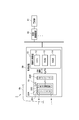
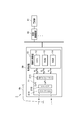
- FIG. 1 is a block diagram illustrating a configuration of the driving support system according to the first embodiment.
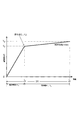
- FIG. 2 is a characteristic diagram showing HDR characteristics of the camera.
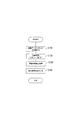
- FIG. 3 is a flowchart for explaining processing executed by the CPU.
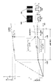
- FIG. 4 is an explanatory diagram for explaining the total conversion characteristics.
- FIG. 5 illustrates the difference between the detection result of the white line based on the total conversion characteristics in the image processing apparatus according to the first embodiment and the detection result of the white line obtained by uniformly compressing the pixel output value with the basic compression ratio.
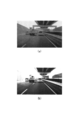
- FIG. 6A is a diagram showing an example of an image obtained by uniformly compressing the pixel output values at the basic compression ratio
- FIG. 6B is an image processing apparatus according to the first embodiment.
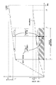
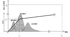
- FIG. 7 is an explanatory diagram showing the luminance distribution for each of a black vehicle, a gray vehicle, and a white vehicle when the recognition target is a vehicle.
- FIG. 8 is an explanatory diagram showing total conversion characteristics in a modification.
- FIG. 9 is an explanatory diagram showing the total conversion characteristics of the modified example.
- FIG. 10 is a block diagram illustrating a configuration of the driving support system according to the second embodiment.
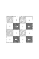
- FIG. 11 is an explanatory diagram showing the arrangement of pixels in the imager.
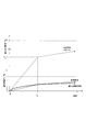
- FIG. 12 is an explanatory diagram for explaining the difference between the detection result based on the total conversion characteristics in the image processing apparatus according to the second embodiment and the detection result obtained by uniformly compressing the pixel output value at the basic compression ratio. .
- the image processing apparatus is applied to a driving support system that is mounted on a vehicle, detects a recognition target existing in front of the vehicle (own vehicle), and executes various driving support controls based on the detection result.
- the driving support system 1 includes an in-vehicle camera (hereinafter simply referred to as a camera) 20 that images the front of the host vehicle VE and outputs the captured image as 12-bit image data.
- This camera functions as an imaging means.
- the driving support system 1 converts the image data output from the camera 20 into 8-bit image data, and uses the image represented by the converted image data to perform image processing according to various applications (applications).
- the image processing apparatus 10 is provided that executes (a process of detecting a recognition target such as a preceding vehicle, a pedestrian, or a white line and outputting a detection result).
- the driving support system 1 uses the detection result of the image processing device 10 to determine whether there is at least a risk that the host vehicle VE deviates from the lane in this embodiment.
- the vehicle control apparatus 40 which instruct
- the camera 20 and the image processing device 10 are referred to as an imaging device 30.
- the camera 20 is installed at a predetermined position in the vehicle interior, for example, behind the rearview mirror, and outputs image data representing an image obtained by imaging the front of the vehicle VE in the traveling direction.
- the camera 20 includes an imager 20A including an image sensor that generates image data representing a captured image, and an input / output interface circuit 20B for the image processing apparatus 10.
- the imager 20A includes a signal processing circuit 202 having a built-in amplification unit and A / D conversion unit in addition to a known CCD image sensor (imaging device) or CMOS image sensor (imaging device) 201.
- the image sensor 201 captures an image
- the amplification unit and the A / D conversion unit amplify an analog signal indicating the luminance of each pixel of the image with a predetermined gain, and the amplified analog value is a first level. It is converted into a digital value represented by a logarithm (here, 12 bits). For this reason, the camera 20 outputs the output pixel value (corresponding to the “first display value”), which is a signal converted into the digital value, as 12-bit imaging data (data string including the output pixel value).
- an imager having a high dynamic range (HDR) characteristic for expanding the dynamic range is used.
- HDR high dynamic range
- the relationship of the output pixel value with respect to the luminance is not constant (linear) in the entire luminance range, but is different (nonlinear) in each luminance range.
- the HDR characteristic includes a range of luminance values 0 to L 1 (hereinafter referred to as luminance ranges 0 to L 1 ) and a remaining luminance range (luminance ranges L 1 to L 2 ).
- luminance ranges 0 to L 1 luminance ranges 0 to L 1
- luminance ranges L 1 to L 2 luminance ranges L 1 to L 2
- such a relationship of broken lines that is, a combination of linear characteristics that differ depending on the luminance range is also included in the nonlinear characteristics.
- the imager 20A can output a wide luminance range while reducing the resolution of the low luminance range.
- the HDR characteristic refers to the relationship between the luminance L and the output pixel value Y shown in FIG. Note that the relationship between the luminance L and the output pixel value Y shown in FIG. 2 shows an example.
- the image processing apparatus 10 is mainly configured by a microcomputer including a CPU 12, a ROM 13, a RAM 14, and a flash memory (not shown). Although not shown, the image processing apparatus 10 includes an interface circuit that inputs and outputs various signals (for example, an input circuit that inputs image data from the camera 20 and an output circuit that outputs detection results to the vehicle control device 40). Prepare. Note that the image processing apparatus 10 is configured to process 8-bit data.
- the image processing apparatus 10 compresses at least 12-bit imaging data input from the camera 20 into 8-bit image data and outputs the compressed data as compressed data. And a recognition target detection process for detecting a recognition target from an image represented by the compressed data. The detection result is output to the vehicle control device 40.
- the vehicle control device 40 is a device for performing driving support control.
- the host vehicle deviates from the lane according to the detection result (the position of the white line) input from the image processing device 10.
- indicates to issue the warning with respect to the warning part 41 may be performed as an application.
- the CPU 12 When the processing starts, the CPU 12 first reads out an output pixel value (imaging data) input from the camera 20 and stored in the RAM 14 in step S110. In step S120, the compression characteristic stored in advance in the ROM 13 is read out, the output pixel value is compressed from 12 bits to 8 bits in accordance with the compression characteristic, and the compressed output pixel value is converted into a compressed pixel value ("second display value"). ”) Is output.
- step S130 a recognition target detection process is performed to detect a recognition target (white line) from an image represented by compressed data, which is a data string composed of 8-bit compressed pixel values.
- step S140 the detection result (the position of the white line) is output to the vehicle control device 40, and this process ends. Since various methods are known for detecting a recognition target in the recognition target detection process, a description thereof will be omitted.
- the compression characteristic is stored in the ROM 13 as a conversion table in which an output pixel value represented by 12 bits and a corresponding compressed pixel value represented by 8 bits are shown.
- a characteristic obtained by combining the compression characteristic and the conversion characteristic is referred to as a total conversion characteristic
- an 8-bit output pixel value which is the number of gradations (corresponding to the “second gradation number”) representing the compression pixel value is A ratio to 12 bits, which is the number of gradations to be represented (corresponding to “first gradation number”) is called a basic compression ratio (2 ⁇ 4 in this case)
- a luminance range estimated to have a recognition target exists Let's say.
- a luminance range including at least the recognition target range is referred to as a designated range
- an output pixel value corresponding to a boundary luminance value that is the minimum luminance value in the designated range is referred to as a boundary first display value.
- the conversion table compression characteristics
- the conversion table includes a low compression value obtained by compressing a value of the output pixel value equal to or higher than the boundary first display value with a low compression ratio ⁇ lower than the basic compression ratio, It is set to be the sum of one display value.
- the recognition target range is set to luminance ranges L 1 to L 3 where a white line that is a recognition target exists.
- the designated range is set such that the boundary luminance value becomes the minimum luminance value in the luminance range including the designated range. That is, in the present embodiment, the designated range is set to match the recognition target range, and the boundary first display value is set to the output pixel value Y 1 corresponding to the boundary luminance value L 1 .
- the compression value (Z 1 ) corresponding to the boundary first display value (Y 1 ) is referred to as a compression basic value Z 1 .
- the conversion table low-compresses the difference between the compression basic value Z 1 , the output pixel value Y, and the boundary first display value Y 1 as shown in Expression (5).
- the sum with the value compressed at the rate ⁇ is set to the compressed pixel value Z.
- the low compression ratio ⁇ is set to 1, and compression in which the low compression ratio ⁇ is set to 1 is referred to as uncompressed. That is, in the uncompressed state, the ratio of change of the compressed pixel value Z with respect to the luminance value L (change ratio after compression) in the specified range is changed by the conversion based on the total conversion characteristics.
- the conversion table is set to be the same as the change ratio before compression).
- the conversion table is set so that the output pixel value Y is converted into the compressed pixel value Z according to the equation (5) for the luminance value L (L> L 3 ) larger than the specified range.
- the output pixel value represented by the first gradation number (12 bits) is the second gradation number smaller than the first gradation number.
- the conversion table used for compression does not use the value obtained by uniformly compressing the output pixel value at the basic compression ratio as the compressed pixel value, Among the pixel values, values exceeding the first display value are set to be compressed with a compression ratio ⁇ lower than the basic compression ratio, and set as a compressed pixel value.
- the conversion table is set so as to be uncompressed.
- the total conversion characteristic is indicated by a dotted line in FIG.
- a characteristic for uniformly compressing pixel output values at a basic compression ratio (referred to as basic compression ratio characteristic) is shown by a solid line in FIG.
- the representative value of the luminance value representing the road surface is set to L R
- the representative value of the luminance value representing the white line is set to L H
- the compressed pixel value Z R and the white line luminance L H corresponding to the road surface luminance L R obtained by the total conversion characteristics are obtained.
- a contrast value C H that is a difference from the corresponding compressed pixel value Z H is expressed by Expression (6).
- the contrast value C P obtained by the basic compression ratio characteristic is represented by the formula (7).
- a larger contrast value CH can be obtained with the total conversion characteristics.
- the image processing apparatus 10 even when the pixel output value is compressed to the compressed pixel value (gradation conversion), a gradation difference is ensured and a reduction in resolution in the recognition target range can be suppressed.
- the image processing apparatus 10 can obtain an image in which the contrast of the white line with respect to the road surface is clearer than when the basic compression ratio characteristic is used (see FIG. 6A) (FIG. 6B). reference). Therefore, in the image represented by the compressed pixel value after compression, it is possible to suppress degradation in detection accuracy of the recognition target.
- FIG. 7 is a diagram illustrating an example of the luminance distribution and the HDR characteristics for the black vehicle, the gray vehicle, and the white vehicle.
- the object containing the change point of the HDR characteristics within the range of the luminance distribution that is, the gray vehicle shown in FIG. 7, the change point luminance value L 1 near In the luminance value L, no gradation difference appears, the resolution is lowered, and the contrast with respect to the road surface is lowered.
- the gray vehicle detection accuracy is lower than that of the black vehicle and the white vehicle.
- the image processing apparatus 10 has a gradation difference in the compressed pixel value with respect to the luminance value L in the vicinity of the change point luminance value L 1 and suppresses a decrease in resolution as compared with the case of uniformly compressing at the basic compression ratio. Therefore, a decrease in contrast with respect to the road surface is suppressed for the gray vehicle. As a result, the image processing apparatus 10 can suppress a decrease in gray vehicle detection accuracy.
- a conversion table (compression characteristic) is set so as to suppress a decrease in resolution for a luminance range in which a white line is estimated to exist.
- the reduction in resolution is suppressed in the recognition target range when the recognition target is a pedestrian (that is, the pedestrian contrast with respect to the road surface becomes clear).
- the compression characteristics may be set. In this way, by setting the compression characteristics according to the application, it is possible to suppress a decrease in the detection accuracy of the recognition target.
- step S110 corresponds to an acquisition unit
- step S120 corresponds to a compression unit
- step S130 corresponds to a recognition unit.
- the low compression ratio ⁇ is set to 1 in the compression characteristics, but the setting of the low compression ratio ⁇ is not limited to this.
- the low compression ratio ⁇ may be set to a compression ratio lower than the basic compression ratio. In this case (beta ⁇ 1), the luminance value Le when compressed pixel value Z becomes 2 8 can be enlarged Le> L4, and the dynamic range.
- the low compression ratio ⁇ similar to that in the designated range is set even in the luminance range larger than the designated range in the compression characteristics.
- the present invention is not limited to this.
- a compression ratio higher than the low compression ratio ⁇ , which is different from the low compression ratio ⁇ may be set. Thereby, the contrast of the white line with respect to the road surface can be clarified and the dynamic range can be expanded.
- the compression ratio ⁇ is set to the basic compression ratio, but the setting of the compression ratio ⁇ is not limited to this.
- the compression ratio ⁇ may be set to a higher compression value than the basic compression ratio.
- the compression characteristic includes the change point luminance value L 1 of the HDR characteristic in the recognition target range (for example, when the recognition target is a gray vehicle with respect to the HDR characteristic as shown in FIG. 7), the total conversion is performed.
- the relationship between the compressed pixel value and the luminance value may be set to be linear within the specified range.
- the compression characteristic may be set so that the relationship of the compressed pixel value to the luminance value is linear.
- the compressed pixel value has a gradation difference due to the conversion based on the total conversion characteristics. Accuracy) can be improved.
- the compression characteristic may be set so that the relationship of the compressed pixel value converted by the total conversion characteristic to the luminance value is expressed in a logarithm (see FIG. 9).
- the specified range is set so that the boundary luminance value matches the change point luminance value, but the specified range may be set so that the boundary luminance value does not match the change point luminance value.
- the designated range does not have to coincide with the recognition target range as in the above-described embodiment, and may be set to a range including at least the recognition target range.
- the driving support system 2 is mounted on a vehicle VE, and detects, for example, a taillight (red) of a preceding vehicle existing in front of the vehicle (own vehicle) VE as a recognition target.
- a taillight red
- the headlight of the host vehicle is set to a low beam when a preceding vehicle is present, and the high beam is set to be high when a preceding vehicle is not present.
- the image processing apparatus 11 has a plurality of pieces of image data representing color images, that is, R (red) and G (green), as imaged data output from the camera 21 (imaging unit). ) And B (blue) are different in that they consist of image data for three channels. Accordingly, part of the processing executed by the CPU 12 is different from the above embodiment.
- the color filter 21A, the imager 21B, and the input / output interface circuit 21C are arranged in this order from the front side of the camera 21. For this reason, light from the outside enters the imager 21B through the color filter 21A.
- the color filter 21A may be integrally provided on the front surface of the imager 21B, or may be disposed on the front surface of the imager 21B as a separate body. As shown in FIG. 11, the color filter 21A selects pixels that selectively detect R (red) light, pixels that selectively detect G (green) light, and B (blue) light.
- the pixels to be detected are configured according to a Bayer array, and the color of an arbitrary pixel is determined from the detection results (pixel output values) of a plurality of pixels adjacent to the pixel.
- the imager 21B outputs, for each pixel, image data for 3 channels of R (red), G (green), and B (blue) (a data string composed of 12-bit pixel output values).
- an imager having an HDR characteristic is used as in the above-described embodiment, and in the following, for the sake of simplicity of explanation, it is assumed that the imager has a characteristic similar to the HDR characteristic shown in FIG.
- the CPU 12 performs the same processing as the flowchart shown in FIG. However, this embodiment is different from the above embodiment in that the imaging data to be processed is image data of three channels of R (red), G (green), and B (blue).
- step S110 image data for three channels of R, G, and B is read in step S110 shown in FIG.
- step S120 according to the compression characteristics (conversion table) stored in the ROM 13, the pixel output values for the R, G, and B channels for each pixel are compressed from 12 bits to 8 bits. , R, G, and B are output as compressed pixel values for three channels.
- step S130 the red taillight of the preceding vehicle is detected as a recognition target from the image represented by the compressed data, which is a data string composed of compressed pixel values for R, G, and B channels.
- FIG. 12 shows a case where the pixel output value corresponding to the representative luminance value Lb representing B (blue) and the representative luminance value Lr representing G (green) is compressed by the image processing device 11.
- R the pixel output value corresponding to the representative luminance value Lb representing B (blue) and the representative luminance value Lr representing G (green) is compressed by the image processing device 11.
- G the pixel output value corresponding to the representative luminance value Lb representing B (blue) and the representative luminance value Lr representing G (green) is compressed by the image processing device 11.
- G compressed data (compressed pixel values) of R, G, and B image data when compressed by basic compression ratio characteristics (see the description of the above embodiment) for comparison Indicates the ratio.
- the reduction ratio of the R compressed data is suppressed by the composition ratio of the R, G, B compressed data, and is recognized as red. be able to.
- the R, G, B image data represented by the first gradation number (12 bits) is the second gradation number smaller than the first gradation number.
- the image data is compressed into R, G, and B image data represented by the number of gradations (8 bits), color misrecognition can be suppressed.
- the detection accuracy of the taillight is improved, and automatic high beam control can be realized with high accuracy.
- the conversion table is set so that the relationship of the compressed pixel value converted by the total conversion characteristic to the luminance value is linear for each luminance range, but the compressed pixel converted by the total conversion characteristic
- the conversion table may be set so that the relationship of the value to the luminance value is represented by a logarithm (see FIG. 9). According to this, since there is no point (change point) where the compressed pixel value suddenly changes with respect to the luminance, the color detection accuracy can be improved.
- the image processing apparatuses 10 and 11 are configured to convert the pixel output value into the compressed pixel value using the conversion table in step S120.
- the present invention is not limited to this.
- the pixel output value may be converted into a compressed pixel value by an equation such as a primary equation or a quadratic equation.
- the HDR characteristic is set so as to make the resolution in the low luminance range fine, but it may be set so as to make the resolution in the high luminance range fine.
- the HDR characteristic is set to a characteristic having one change point in the above embodiment, but may be set to a characteristic having a plurality of change points.
- the lane keeping control and the auto high beam control are executed as the application executed by the driving support system.
- the driving support device detects, for example, the front vehicle as a recognition target by the vehicle control device, and the inter-vehicle control that secures the inter-vehicle distance from the detected front vehicle, the follow-up control that travels following the front vehicle, or the recognition
- Various driving support controls such as avoidance control for controlling a vehicle so as to avoid the detected pedestrian, may be configured to be executed as an application.
- the components of the image processing apparatus exemplified in the above embodiment may be realized by hardware, software, or a combination of hardware and software.
- you may comprise at least one part of an image processing apparatus by the computer apparatus (for example, microcomputer) which performs the process (program) mentioned above.
- These components are functionally conceptual, and some or all of them may be functionally or physically distributed or integrated.
- the above embodiment is merely an example of an embodiment to which the present invention is applied.
- the present invention can be realized in various forms such as an image processing apparatus, an image processing method, a program for causing a computer to function as the image processing apparatus, and a recording medium on which the program is recorded.
Landscapes
- Engineering & Computer Science (AREA)
- Multimedia (AREA)
- Signal Processing (AREA)
- Physics & Mathematics (AREA)
- General Physics & Mathematics (AREA)
- Theoretical Computer Science (AREA)
- Image Processing (AREA)
- Facsimile Image Signal Circuits (AREA)
- Studio Devices (AREA)
- Closed-Circuit Television Systems (AREA)
Abstract
Description
[第1実施形態]
本実施形態の画像処理装置は、車両に搭載され、車両(自車両)の前方に存在する認識対象を検出し、検出結果に基づく各種運転支援制御を実行する運転支援システムに適用される。


ここで、圧縮特性と変換特性とを組み合わせた特性を総合変換特性といい、圧縮画素値を表す階調数(「第2の階調数」に相当)である8ビットの、出力画素値を表す階調数(「第1の階調数」に相当)である12ビットに対する比を基本圧縮比(ここでは2-4)といい、認識対象が存在すると推定される輝度範囲を認識対象範囲というものとする。
変換テーブル(圧縮特性)は、指定範囲では、圧縮画素値が、出力画素値のうち境界第1表示値以上の値を基本圧縮比より低い低圧縮比βで圧縮した低圧縮値と、境界第1表示値との和となるように、設定されている。


このように、画像処理装置10では、画素出力値を圧縮画素値に圧縮(階調変換)した場合にも、階調差が確保され、認識対象範囲における分解能の低下を抑制することができる。これにより、画像処理装置10では、基本圧縮比特性を用いた場合(図6(a)参照)と比べて、路面に対する白線のコントラストがより鮮明な画像を得ることができる(図6(b)参照)。従って、圧縮後の圧縮画素値により表される画像において、認識対象の検出精度の劣化を抑制することができる。
上記実施形態では、圧縮特性にて、低圧縮比βが1に設定されていたが、低圧縮比βの設定はこれに限るものではない。低圧縮比βは、基本圧縮比より低い圧縮比に設定されていればよい。この場合(β≠1)、圧縮画素値Zが28となるときの輝度値LeはLe>L4となり、ダイナミックレンジを拡大することができる。
圧縮特性は、認識対象範囲にHDR特性の変化点輝度値L1を含む場合(例えば図7に示すように、HDR特性に対して認識対象を灰色車両とするような場合)には、総合変換特性による変換によって、圧縮画素値の輝度値に対する関係が指定範囲内で線形となるように設定されていてもよい。
圧縮特性は、総合変換特性によって変換された圧縮画素値の輝度値に対する関係が対数で表されるように設定されていてもよい(図9参照)。
上記実施形態では、指定範囲は、変化点輝度値に境界輝度値が一致するように設定されていたが、指定範囲は、変化点輝度値に境界輝度値が一致しないように設定されてもよい。また、指定範囲は、上記実施形態のように認識対象範囲に一致していなくてもよく、少なくとも認識対象範囲を含む範囲に設定されていればよい。
次に第2実施形態について説明する。なお、この実施形態の説明において、前述した第1の実施形態の装置を構成する要素と同一又は同等のものには同一符号を用いて、その説明を省略又は簡略化する。
本発明は、撮像装置がカラー撮影を行うように構成されている場合にも適用できる。図10に示すように、本実施形態の運転支援システム2は、車両VEに搭載され、例えば、認識対象として車両(自車両)VEの前方に存在する先行車のテールライト(赤色)を検出することで、先行車が存在する場合には自車両のヘッドライトをロービームにし、先行車が存在しない場合にはハイビームにするといったオートハイビーム制御を実現する。
(1)上記実施形態では、画像処理装置10、11は、ステップS120にて変換テーブルを用いて画素出力値を圧縮画素値に変換するように構成されていたが、これに限るものではなく、ステップS120にて一次式又は二次式等の数式により画素出力値を圧縮画素値に変換するように構成されてもよい。
10、11・・・画像処理装置
20、21・・・カメラ(撮像手段)
20A,21B・・・イメージャ(撮像素子)
30、31・・・撮像装置
40、42・・・車両制御装置
Claims (9)
- 輝度値を予め設定された非線形な変換特性で変換し第1の階調数で表した第1表示値からなるデータ列である撮像データを撮像素子から取得する取得手段(S110)と、
前記第1表示値を予め設定された圧縮特性で圧縮し、前記第1の階調数より小さい第2の階調数で表した値を第2表示値として出力する圧縮手段(S120)と、
前記第2表示値からなるデータ列である圧縮データによって表される画像から認識対象を検出する認識手段(S130)と、
を備え、
前記第2の階調数の前記第1の階調数に対する比を基本圧縮比とし、前記認識対象が存在すると推定される輝度範囲である認識対象範囲を少なくとも含む輝度範囲を指定範囲とし、該指定範囲にて最小の輝度値である境界輝度値に対応する前記第1表示値を境界第1表示値として、
前記圧縮特性は、前記認識対象範囲では、前記第2表示値が、前記第1表示値のうち前記境界第1表示値以上の値を前記基本圧縮比より低い低圧縮比で圧縮した値と、前記境界第1表示値との和となるように設定されていること、
を特徴とする画像処理装置。 - 前記圧縮特性は、前記指定範囲にて前記低圧縮比が1となるように設定されていること、を特徴とする請求項1に記載の画像処理装置。
- 前記変換特性は、輝度範囲毎に予め定められた線形な特性の組み合わせとして設定されており、
前記指定範囲は、前記境界輝度値が、前記指定範囲を含む前記輝度範囲にて最小の輝度値となるように設定されていること、を特徴とする請求項1または2に記載の画像処理装置。 - 前記指定範囲は、前記認識対象範囲に一致するように設定されていること、を特徴とする請求項1から3のいずれか一項に記載の画像処理装置。
- 前記変換特性は、輝度範囲毎に予め定められた線形な特性の組み合わせとして設定され、
前記指定範囲は、前記変換特性にて前記線形な特性が変化する変化点での輝度値を変化点輝度値として、前記認識対象範囲に前記変化点輝度値を含むように設定され、
前記圧縮特性は、前記圧縮特性と前記変換特性とを組み合わせた特性を総合変換特性として、少なくとも前記指定範囲では、前記総合変換特性によって変換された前記第2表示値の前記輝度値に対する関係が線形となるように設定されていること、を特徴とする請求項1または2に記載の画像処理装置。 - 前記圧縮特性は、前記圧縮特性と前記変換特性とを組み合わせた特性を総合変換特性として、前記総合変換特性によって変換された前記輝度値に対する前記第2表示値の関係が対数で表されるように設定されていること、を特徴とする請求項1に記載の画像処理装置。
- 前記撮像データは、カラー画像を表す複数の画像データからなり、
前記圧縮手段は、前記複数の画像データのそれぞれについて、前記第1表示値を前記圧縮特性で圧縮し前記第2の階調数で表して前記第2表示値として出力すること、を特徴とする請求項1に記載の画像処理装置。 - 前記撮像素子は、車両に搭載されたカメラの撮像素子であり、
前記画像処理装置は、前記車両に搭載され、当該車両の前方に存在する認識対象を検出し、その検出結果に基づいて運転支援制御を実行する運転支援システムの一部を構成していることを特徴とする請求項1から請求項7のいずれか一項に記載の画像処理装置。 - 輝度値を予め設定された非線形な変換特性で変換し第1の階調数で表した第1表示値からなるデータ列である撮像データを撮像素子から取得する取得ステップ(S110)と、
前記第1表示値を予め設定された圧縮特性で圧縮し、前記第1の階調数より小さい第2の階調数で表した値を第2表示値として出力する圧縮ステップ(S120)と、
前記第2表示値からなるデータ列である圧縮データによって表される画像から認識対象を検出する認識ステップ(S130)と、
を備え、
前記第2の階調数の前記第1の階調数に対する比を基本圧縮比とし、前記認識対象が存在すると推定される輝度範囲である認識対象範囲を少なくとも含む輝度範囲を指定範囲とし、該指定範囲にて最小の輝度値である境界輝度値に対応する前記第1表示値を境界第1表示値として、
前記圧縮特性は、前記認識対象範囲では、前記第2表示値が、前記第1表示値のうち前記境界第1表示値以上の値を前記基本圧縮比より低い低圧縮比で圧縮した値と、前記境界第1表示値との和となるように設定されていること、
を特徴とする画像処理方法。
Priority Applications (3)
| Application Number | Priority Date | Filing Date | Title |
|---|---|---|---|
| CN201480025880.6A CN105190687B (zh) | 2013-05-07 | 2014-04-30 | 图像处理装置以及图像处理方法 |
| US14/889,789 US9800881B2 (en) | 2013-05-07 | 2014-04-30 | Image processing apparatus and image processing method |
| DE112014002331.0T DE112014002331T5 (de) | 2013-05-07 | 2014-04-30 | Bildverarbeitungsvorrichtung und Bildverarbeitungsverfahren |
Applications Claiming Priority (2)
| Application Number | Priority Date | Filing Date | Title |
|---|---|---|---|
| JP2013-097664 | 2013-05-07 | ||
| JP2013097664A JP6064776B2 (ja) | 2013-05-07 | 2013-05-07 | 画像処理装置及び画像処理方法 |
Publications (1)
| Publication Number | Publication Date |
|---|---|
| WO2014181743A1 true WO2014181743A1 (ja) | 2014-11-13 |
Family
ID=51867224
Family Applications (1)
| Application Number | Title | Priority Date | Filing Date |
|---|---|---|---|
| PCT/JP2014/061987 Ceased WO2014181743A1 (ja) | 2013-05-07 | 2014-04-30 | 画像処理装置及び画像処理方法 |
Country Status (5)
| Country | Link |
|---|---|
| US (1) | US9800881B2 (ja) |
| JP (1) | JP6064776B2 (ja) |
| CN (1) | CN105190687B (ja) |
| DE (1) | DE112014002331T5 (ja) |
| WO (1) | WO2014181743A1 (ja) |
Cited By (1)
| Publication number | Priority date | Publication date | Assignee | Title |
|---|---|---|---|---|
| US9800881B2 (en) | 2013-05-07 | 2017-10-24 | Denso Corporation | Image processing apparatus and image processing method |
Families Citing this family (8)
| Publication number | Priority date | Publication date | Assignee | Title |
|---|---|---|---|---|
| JP6390512B2 (ja) * | 2015-05-21 | 2018-09-19 | 株式会社デンソー | 車載カメラ装置 |
| JP6912957B2 (ja) * | 2016-10-04 | 2021-08-04 | キヤノン株式会社 | 画像処理装置、画像処理方法およびプログラム |
| EP3636490B1 (en) * | 2017-06-09 | 2023-05-24 | Koito Manufacturing Co., Ltd. | Vehicular lamp, and device and method for controlling same |
| JP7151234B2 (ja) * | 2018-07-19 | 2022-10-12 | 株式会社デンソー | カメラシステムおよびイベント記録システム |
| US11699207B2 (en) | 2018-08-20 | 2023-07-11 | Waymo Llc | Camera assessment techniques for autonomous vehicles |
| US11227409B1 (en) | 2018-08-20 | 2022-01-18 | Waymo Llc | Camera assessment techniques for autonomous vehicles |
| JP7217211B2 (ja) * | 2019-08-23 | 2023-02-02 | 日立Astemo株式会社 | 撮像装置及び撮像方法 |
| JP7618603B2 (ja) * | 2022-01-28 | 2025-01-21 | キヤノン株式会社 | カメラシステム、移動体、カメラシステムの制御方法、及びコンピュータプログラム |
Citations (10)
| Publication number | Priority date | Publication date | Assignee | Title |
|---|---|---|---|---|
| JP2000115534A (ja) * | 1998-09-30 | 2000-04-21 | Fuji Photo Film Co Ltd | 画像処理方法および装置並びに記録媒体 |
| JP2001086365A (ja) * | 1999-09-14 | 2001-03-30 | Matsushita Electric Ind Co Ltd | ガンマ補正回路およびニー補正回路 |
| JP2004221645A (ja) * | 2003-01-09 | 2004-08-05 | Sony Corp | 画像処理装置および方法、記録媒体、並びにプログラム |
| JP2006237851A (ja) * | 2005-02-23 | 2006-09-07 | Mitsubishi Electric Corp | 画像入力装置 |
| WO2006098360A1 (ja) * | 2005-03-15 | 2006-09-21 | Omron Corporation | 画像処理装置および画像処理方法、画像処理システム、プログラム、並びに、記録媒体 |
| WO2006103881A1 (ja) * | 2005-03-29 | 2006-10-05 | Konica Minolta Photo Imaging, Inc. | 撮像装置 |
| JP2007082180A (ja) * | 2005-08-16 | 2007-03-29 | Konica Minolta Holdings Inc | 撮像装置及び画像処理方法 |
| JP2008289120A (ja) * | 2007-04-18 | 2008-11-27 | Panasonic Corp | 撮像装置、撮像方法、集積回路およびプログラム |
| WO2009057478A1 (ja) * | 2007-11-01 | 2009-05-07 | Konica Minolta Opto, Inc. | 画像処理装置、画像処理方法、及び撮像装置 |
| WO2011155136A1 (ja) * | 2010-06-07 | 2011-12-15 | コニカミノルタオプト株式会社 | 撮像装置 |
Family Cites Families (9)
| Publication number | Priority date | Publication date | Assignee | Title |
|---|---|---|---|---|
| KR101051604B1 (ko) | 2003-01-09 | 2011-07-22 | 소니 주식회사 | 화상 처리 장치 및 방법 |
| US7791656B2 (en) | 2005-08-16 | 2010-09-07 | Konica Minolta Holdings, Inc. | Image sensing apparatus and image processing method |
| US8144214B2 (en) | 2007-04-18 | 2012-03-27 | Panasonic Corporation | Imaging apparatus, imaging method, integrated circuit, and storage medium |
| JP2008305122A (ja) | 2007-06-07 | 2008-12-18 | Sony Corp | 画像処理装置、画像処理方法、およびプログラム |
| JP5275122B2 (ja) * | 2008-05-30 | 2013-08-28 | パナソニック株式会社 | ダイナミックレンジ圧縮装置、ダイナミックレンジ圧縮方法、プログラム、集積回路および撮像装置 |
| JP4632100B2 (ja) * | 2008-06-09 | 2011-02-16 | ソニー株式会社 | 画像処理装置、画像処理方法、記録媒体、およびプログラム |
| JP2010219624A (ja) * | 2009-03-13 | 2010-09-30 | Toshiba Corp | 画像信号処理装置及び画像信号処理方法 |
| JP2012208776A (ja) * | 2011-03-30 | 2012-10-25 | Fujitsu Ltd | 画像処理装置、画像処理方法およびプログラム |
| JP6064776B2 (ja) | 2013-05-07 | 2017-01-25 | 株式会社デンソー | 画像処理装置及び画像処理方法 |
-
2013
- 2013-05-07 JP JP2013097664A patent/JP6064776B2/ja active Active
-
2014
- 2014-04-30 US US14/889,789 patent/US9800881B2/en active Active
- 2014-04-30 WO PCT/JP2014/061987 patent/WO2014181743A1/ja not_active Ceased
- 2014-04-30 DE DE112014002331.0T patent/DE112014002331T5/de not_active Withdrawn
- 2014-04-30 CN CN201480025880.6A patent/CN105190687B/zh not_active Expired - Fee Related
Patent Citations (10)
| Publication number | Priority date | Publication date | Assignee | Title |
|---|---|---|---|---|
| JP2000115534A (ja) * | 1998-09-30 | 2000-04-21 | Fuji Photo Film Co Ltd | 画像処理方法および装置並びに記録媒体 |
| JP2001086365A (ja) * | 1999-09-14 | 2001-03-30 | Matsushita Electric Ind Co Ltd | ガンマ補正回路およびニー補正回路 |
| JP2004221645A (ja) * | 2003-01-09 | 2004-08-05 | Sony Corp | 画像処理装置および方法、記録媒体、並びにプログラム |
| JP2006237851A (ja) * | 2005-02-23 | 2006-09-07 | Mitsubishi Electric Corp | 画像入力装置 |
| WO2006098360A1 (ja) * | 2005-03-15 | 2006-09-21 | Omron Corporation | 画像処理装置および画像処理方法、画像処理システム、プログラム、並びに、記録媒体 |
| WO2006103881A1 (ja) * | 2005-03-29 | 2006-10-05 | Konica Minolta Photo Imaging, Inc. | 撮像装置 |
| JP2007082180A (ja) * | 2005-08-16 | 2007-03-29 | Konica Minolta Holdings Inc | 撮像装置及び画像処理方法 |
| JP2008289120A (ja) * | 2007-04-18 | 2008-11-27 | Panasonic Corp | 撮像装置、撮像方法、集積回路およびプログラム |
| WO2009057478A1 (ja) * | 2007-11-01 | 2009-05-07 | Konica Minolta Opto, Inc. | 画像処理装置、画像処理方法、及び撮像装置 |
| WO2011155136A1 (ja) * | 2010-06-07 | 2011-12-15 | コニカミノルタオプト株式会社 | 撮像装置 |
Cited By (1)
| Publication number | Priority date | Publication date | Assignee | Title |
|---|---|---|---|---|
| US9800881B2 (en) | 2013-05-07 | 2017-10-24 | Denso Corporation | Image processing apparatus and image processing method |
Also Published As
| Publication number | Publication date |
|---|---|
| US9800881B2 (en) | 2017-10-24 |
| JP2014219790A (ja) | 2014-11-20 |
| CN105190687B (zh) | 2017-10-10 |
| US20160105679A1 (en) | 2016-04-14 |
| CN105190687A (zh) | 2015-12-23 |
| DE112014002331T5 (de) | 2016-01-21 |
| JP6064776B2 (ja) | 2017-01-25 |
Similar Documents
| Publication | Publication Date | Title |
|---|---|---|
| JP6064776B2 (ja) | 画像処理装置及び画像処理方法 | |
| KR101367637B1 (ko) | 감시장치 | |
| US9906766B2 (en) | Imaging device | |
| JP6029954B2 (ja) | 撮像装置 | |
| US10136080B2 (en) | Image generating apparatus | |
| US10298856B2 (en) | Imaging device | |
| JP2016126750A (ja) | 画像処理システム、画像処理装置、撮像装置、画像処理方法、プログラムおよび記録媒体 | |
| JP5861924B2 (ja) | 撮像装置 | |
| US9131199B2 (en) | Imaging apparatus capable of generating an appropriate color image | |
| JP4089911B2 (ja) | 画像入力装置 | |
| US10063827B2 (en) | Image processing apparatus, imaging apparatus, image processing program, and image processing method | |
| JP4400512B2 (ja) | 車載カメラ制御装置 | |
| US10783619B2 (en) | Image generating apparatus for combining plural images based on different shutter times | |
| JP2020064052A (ja) | 熱画像データをフィルタリングするための方法およびシステム | |
| US20120243791A1 (en) | Method and apparatus for classifying image pixels | |
| US12375801B2 (en) | Camera system, movable apparatus, camera system control method, and storage medium | |
| US12137308B2 (en) | Image processing apparatus | |
| JP6833751B2 (ja) | 撮像制御装置、撮像装置、及び撮像制御方法 | |
| JP2012075059A (ja) | 画像処理装置 | |
| JP6525723B2 (ja) | 撮像装置及びその制御方法、プログラム、並びに記憶媒体 | |
| JP2007013687A (ja) | 液晶シャッタによるアイリス調整機能付き撮像装置 | |
| WO2018047495A1 (ja) | 画像処理装置および配光制御システム | |
| CN116249026A (zh) | 图像传感器的信号处理装置和方法 | |
| JP2013126115A (ja) | 信号処理装置、撮像装置 |
Legal Events
| Date | Code | Title | Description |
|---|---|---|---|
| WWE | Wipo information: entry into national phase |
Ref document number: 201480025880.6 Country of ref document: CN |
|
| 121 | Ep: the epo has been informed by wipo that ep was designated in this application |
Ref document number: 14795472 Country of ref document: EP Kind code of ref document: A1 |
|
| WWE | Wipo information: entry into national phase |
Ref document number: 14889789 Country of ref document: US |
|
| WWE | Wipo information: entry into national phase |
Ref document number: 1120140023310 Country of ref document: DE Ref document number: 112014002331 Country of ref document: DE |
|
| 122 | Ep: pct application non-entry in european phase |
Ref document number: 14795472 Country of ref document: EP Kind code of ref document: A1 |