WO2014181599A1 - 材料臭気試験装置及びそれに用いられる材料臭気検査方法 - Google Patents
材料臭気試験装置及びそれに用いられる材料臭気検査方法 Download PDFInfo
- Publication number
- WO2014181599A1 WO2014181599A1 PCT/JP2014/058795 JP2014058795W WO2014181599A1 WO 2014181599 A1 WO2014181599 A1 WO 2014181599A1 JP 2014058795 W JP2014058795 W JP 2014058795W WO 2014181599 A1 WO2014181599 A1 WO 2014181599A1
- Authority
- WO
- WIPO (PCT)
- Prior art keywords
- sample
- container
- discharge flow
- material odor
- discharge
- Prior art date
- Legal status (The legal status is an assumption and is not a legal conclusion. Google has not performed a legal analysis and makes no representation as to the accuracy of the status listed.)
- Ceased
Links
Images





Classifications
-
- G—PHYSICS
- G01—MEASURING; TESTING
- G01N—INVESTIGATING OR ANALYSING MATERIALS BY DETERMINING THEIR CHEMICAL OR PHYSICAL PROPERTIES
- G01N1/00—Sampling; Preparing specimens for investigation
- G01N1/02—Devices for withdrawing samples
- G01N1/22—Devices for withdrawing samples in the gaseous state
- G01N1/2226—Sampling from a closed space, e.g. food package, head space
Definitions
- the present invention relates to a material odor test apparatus for measuring a diffuse odor of a sample such as a food and a material odor test method used therefor.
- an inhibition model device capable of measuring the emitted odor during inhibition after grasping such inhibition characteristics is disclosed (for example, see Non-Patent Document 1).
- the strength test of the target sample is performed in a cylindrical sealed container made of a transparent material such as glass or acrylic, and then a Tenax (registered trademark) tube is placed in the sealed container. It is connected or connected to a PTR-MS or the like and purged with an inert gas (for example, nitrogen gas) or clean air to measure the diffuse odor during the simulated inhibition.
- an inert gas for example, nitrogen gas
- FIG. 8 is a schematic configuration diagram showing a material testing apparatus for performing a three-point bending strength test.
- One direction horizontal to the ground is defined as an X direction
- a direction horizontal to the ground and perpendicular to the X direction is defined as a Y direction
- a direction perpendicular to the X direction and the Y direction is defined as a Z direction.
- the material test apparatus 101 includes a machine base 7, a casing 14 that rotatably supports two screw shafts 5 and 13 whose vertical direction (Z direction) is a rotation axis, and a central portion on the upper surface of the machine base 7.
- a support base 112 provided; a crosshead 8 that can be screwed into the screw shafts 5 and 13 and moved vertically with respect to the machine base 7 as the screw shafts 5 and 13 rotate; A load cell 111 fixed at the center of the lower surface and an arithmetic control unit 103 that performs control and arithmetic processing are provided.
- a motor 4 controlled by a control signal from the arithmetic control unit 103, a belt 61 that transmits the rotational force from the motor 4 to the screw shafts 5 and 13, and an interlocking pulley 62 are connected inside the machine base 7.
- a gear mechanism 6 is arranged inside the machine base 7.
- Two plate-like supports 130 that are parallel to each other are attached to the upper surface of the support 112 so as to be aligned in the X direction.
- one plunger (pressing part) 120 is attached to the lower surface of the load cell 111. With such a support 130 and the plunger 120, the plate-shaped test piece S is placed with the upper ends of the two supports 130 as a fulcrum, and the load W is set with the lower end of the plunger 120 as a load point. The test piece S is loaded on a predetermined part.
- the inhibition model apparatus as described above has a problem that it is impossible to measure the time change of the diffuse odor of the sample.
- aroma components are released from the food in the oral cavity, but even if the diffuse odor at the beginning and the diffuse odor at the end are different, The diffuse odor at the time and the diffuse odor at the end were accumulated in the sealed container, and the diffuse odor present in the sealed container was measured.
- the present inventor has examined a material odor test apparatus capable of measuring a time change of a diffuse odor of a sample. Therefore, instead of using a sealed container, an introduction pipe for introducing gas into the container and a discharge pipe for discharging gas from the inside of the container are connected, and the discharge pipes are connected to a plurality of discharge flow paths. It has been found that one discharge channel is selected and connected from among a plurality of discharge channels for every set time and for each set circulation volume.
- the material odor test apparatus of the present invention includes a sample mounting table on which a sample is mounted, a pressing unit that applies a load to the sample, a container, and a control unit that controls the pressing unit, and the container Inside, there is a material odor test apparatus in which the pressing part, the sample mounting table and the sample are arranged, and the container is an introduction tube for introducing gas into the container And a discharge pipe for discharging gas from the inside of the container, the discharge pipe is branched into a plurality of discharge flow paths, and one discharge selected from the plurality of discharge flow paths A switching mechanism that can be connected to the flow path is provided.
- the switching mechanism since the switching mechanism is provided, it is possible to select and connect one discharge flow path from among a plurality of discharge flow paths for each set time or set flow volume, and as a result. It is possible to capture changes in gas generated in a single material test.
- an adsorption portion that adsorbs a component contained in the gas is disposed in each discharge channel, and a suction pump is disposed at the outlet of the discharge channel. You may do it.
- the “adsorbing portion” may be anything that can adsorb components contained in the gas.
- a test tube in which an adsorbent or the like for example, Tenax (registered trademark) is accommodated. Etc.
- a bag may be disposed at the outlet of each discharge flow path, and an extrusion pump may be disposed at the inlet of the introduction pipe.
- the control unit may switch the discharge flow path through which the gas flows by the switching mechanism based on a set time, a set flow volume, or the number of presses of the press unit.
- control unit may control the suction pump or the extrusion pump.
- the suction pump and the extrusion pump can be started at the same timing as the start of the test, or can be started in advance.
- an XY stage may be provided, and the sample mounting table may be attached to the XY stage.
- the position where the pressing portion abuts against the sample can be changed by sliding on the XY stage.
- the container may be a transparent resin bag, and the pressing portion, the sample mounting table, and the sample may be disposed in the container.
- transparent resin used for a bag a fluororesin etc. are mentioned, for example.
- the material odor inspection method of this invention is equipped with the sample mounting base in which a sample is mounted, the press part which loads a load to the said sample, a container, and the control part which controls the said press part,
- the said container Inside, there is a material odor inspection method used in a material odor test apparatus in which the pressing portion, the sample mounting table, and the sample are arranged, and gas is introduced into the container.
- a connecting step for connecting an introduction pipe for introduction, a discharge pipe for discharging gas from the container, and the discharge pipe is branched into a plurality of discharge flow paths,
- a switching mechanism that can be connected to one discharge flow path selected from the inside is arranged to include an inspection step for controlling the switching mechanism and the pressing portion.
- the above invention may include an analysis step of individually introducing the gas flowing through each discharge channel into the analyzer.
- the “analyzer” may be any device that can measure the emitted odor of the sample.
- gas chromatography GC
- GCMS gas chromatography mass spectrometer
- HPLC high performance liquid chromatography
- FF Odor identification device
- FIG. 3 is an exploded sectional view of FIG. 2.
- FIG. 4 is an exploded cross-sectional view of FIG. 3.
- the schematic block diagram which shows the material testing apparatus for performing a 3 point
- the graph which shows the change of the peak area value about each fragrance
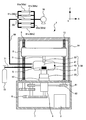
- FIG. 1 is a schematic configuration diagram illustrating a material odor test apparatus according to an embodiment of the present invention
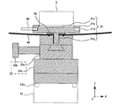
- FIG. 2 is an enlarged cross-sectional view illustrating a sample holder and an XY stage in FIG. 1, and FIG. It is an expanded sectional view of the press body shown in FIG.
- symbol is attached
- FIG. The sample S in this embodiment has a cylindrical shape with a diameter of 40 mm and a height of 15 mm, and the case where the time change of the emitted odor of the sample S is measured by GCMS will be described.
- the material odor test apparatus 1 includes a machine base 7, a casing 14 that rotatably supports two screw shafts 5 and 13 whose vertical direction (Z direction) is a rotation axis, and a central portion on the upper surface of the machine base 7.
- It includes an introduction pipe 71 connected to a gas supply source 72, a discharge pipe 60 connected to a suction pump 70 and the like, and an arithmetic control unit 3 that performs control and arithmetic processing.
- the XY stage 33 can be fixed to the upper surface of the first mounting portion 12 using four screws 12a and the like.
- a screw hole 11a (for example, 6 mm in diameter) carved upward is formed in the center of the lower surface of the load cell 11, and the adapter body 22 can be attached and detached by a screw mechanism.
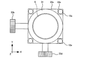
- FIG. 4 is a plan view showing the sample holder 31 and the XY stage 33
- FIG. 5 is an exploded sectional view of FIG.
- the XY stage 33 includes an aluminum (metal) rectangular parallelepiped (for example, 60 mm ⁇ 40 mm ⁇ 8 mm) X stage 33c to be fixed to the first mounting portion 12, and aluminum (metal) disposed above the X stage.
- a Y-stage 33a having a rectangular parallelepiped shape (for example, 40 mm ⁇ 60 mm ⁇ 22 mm).
- a handle 33d protruding in the Y direction is formed on the X stage 33c, and the operator or the like rotates the handle 33d to move the upper part of the X stage 33c in the X direction with respect to the lower part of the X stage 33c. Be able to.
- the Y stage 33a is formed with a handle 33b protruding in the X direction. When a measurer or the like rotates the handle 33b, the upper part of the Y stage 33a extends in the Y direction with respect to the lower part of the Y stage 33a. It can be moved.
- a screw hole 33e (for example, 6 mm in diameter) carved downward is formed at the center of the upper surface of the Y stage 33a, and the sample holder 31 can be attached and removed by a screw mechanism.
- the sample holder 31 is made of polytetrafluoroethylene (PTFE) disk-shaped (for example, 60 mm in diameter and 10 mm in height) and a PTFE made of PTFE protruding downward from the center of the lower surface of the sample mounting 31 a. And a threaded portion (for example, a diameter of 6 mm) 31b.
- PTFE polytetrafluoroethylene
- a groove 31c having a cylindrical shape (for example, 42 mm in diameter and 3 mm in depth) having a depth of 15% of the height of the sample S and a diameter 2 mm larger than the diameter of the sample S is formed on the upper surface of the sample mounting table 31a. Yes. Thereby, the sample S having a diameter of 40 mm and a height of 15 mm is placed in the groove 31c.
- a cylindrical handle hole 31d carved laterally is formed on the side surface of the sample mounting table 31a.
- the screw portion 31 b is inserted into a PTFE washer 32 (for example, 2 mm thick), inserted into the first hole 42 of the sample back 40, and a rubber O-ring. After being inserted into 34, it is inserted into the screw hole 33e.
- the measurer or the like inserts the rod-like handle 60 into the handle hole 31d and rotates the screw portion 31b using the handle 60 in order to fix the screw portion 31b in the screw hole 33e.
- FIG. 6 is an exploded cross-sectional view of FIG.
- the adapter body 22 includes an aluminum (metal) columnar shape (for example, a diameter of 22 mm and a height of 15 mm), and an aluminum screw portion 22b (for example, a diameter) protruding upward from the center of the upper surface of the body portion 22a. 6 mm). And in the center part of the lower surface of the main-body part 22a, the one screw hole 22c (for example, diameter 6mm) carved upwards is formed, and the press body 21 can be attached or removed with a screw mechanism. Further, a cylindrical handle hole 22d carved laterally is formed on the side surface of the main body 22a.
- the screw portion 22 b is inserted into the screw hole 11 a of the load cell 11.
- the measurer or the like inserts the rod-like handle 60 into the handle hole 22d and rotates the screw portion 22b using the handle 60 in order to fix the screw portion 22b in the screw hole 11a.
- the pressing body 21 includes a PTFE columnar shape (for example, a diameter of 22 mm, a height of 5 mm) and a PTFE columnar shape (for example, a diameter of 8 mm, a height) projecting downward from the central portion of the lower surface of the body portion 21a.
- a cylindrical handle hole 21d carved laterally is formed on the side surface of the main body 21a.
- the screw portion 21 c is inserted into the annular washer 23 made of PTFE (for example, 2 mm in thickness), inserted into the second hole 41 of the sample back 40, and a rubber O-ring. After being inserted into 24, it is inserted into the screw hole 22c. At this time, the measurer or the like inserts the rod-like handle 60 into the handle hole 21d and rotates the screw portion 21c using the handle 60 in order to fix the screw portion 21c in the screw hole 22c.
- the measurer or the like inserts the rod-like handle 60 into the handle hole 21d and rotates the screw portion 21c using the handle 60 in order to fix the screw portion 21c in the screw hole 22c.
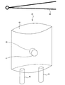
- FIG. 7 is a perspective view showing the sample bag 40 and the clip 49.
- the sample bag 40 is made of a transparent vinyl bag (for example, an opening 43 formed by bonding three sides of a first vinyl of 215 mm ⁇ 250 mm and three sides of a second vinyl of 215 mm ⁇ 250 mm).
- the first vinyl 42 has a circular shape (for example, 6 mm in diameter) through which the screw portion 31b penetrates the central portion of the first vinyl, and the screw portion 21c penetrates the central portion of the second vinyl.
- the second hole 41 having a circular shape (for example, a diameter of 6 mm) is formed.
- an introduction pipe connection pipe 45 for connecting to the introduction pipe 71 and a discharge pipe connection pipe 44 for connecting to the discharge pipe 60 are formed on the bottom of the sample bag 40.
- the clip 49 is for closing the opening 43.
- the inert gas supply source 72 (see FIG. 1) is a tank (such as a container or a cylinder) in which an inert gas (for example, nitrogen gas) is stored.
- an inert gas for example, nitrogen gas
- One end of the introduction pipe 71 is connected to the inert gas supply source 72, and the other end of the introduction pipe 71 is connected to the introduction pipe connection pipe 45.
- the discharge pipe 60 branches into five discharge flow paths 61a to 61e between one end and the other end, and then gathers again to form one pipe.
- test tubes 62a to 62e each containing an adsorbent can be attached and detached.
- a switching mechanism (flow path switching valve) 63 is disposed at a branch point where the five discharge flow paths 61a to 61e branch. The switching mechanism 63 can be connected to one discharge flow path 61 selected from among the five discharge flow paths 61a to 61e by a control signal from the arithmetic control unit 3.
- the arithmetic control unit 3 performs control to start measurement when a measurement start signal is input by a measurer or the like. For example, when a measurement start signal (setting information such as the number of times of pressing four times at a set time (0.30 minute interval)) is input, the suction pump 70 is first operated and the switching mechanism 63 is switched to discharge By connecting with the flow path 61a, a fixed amount of gas is circulated in the order of the discharge flow path 61a from the inert gas supply source 72 through the sample bag 40.
- a measurement start signal setting information such as the number of times of pressing four times at a set time (0.30 minute interval)
- the switching mechanism 63 is switched and connected to the discharge flow path 61b, and from the inert gas supply source 72 through the sample back 40 and the discharge flow path 61b. A certain amount of gas is circulated in this order.
- the pressing body 21 starts to descend at a constant speed (for example, 100 mm / min), descends at a constant speed for 0.15 minutes, and then rises at a constant speed for 0.15 minutes.
- the switching mechanism 63 is switched and connected to the discharge flow path 61c, and the inert gas supply source 72 passes through the sample back 40 and the discharge flow path 61c.
- a certain amount of gas is circulated in order.
- the pressing body 21 starts to descend at a constant speed (for example, 100 mm / min), descends at a constant speed for 0.15 minutes, and then rises at a constant speed for 0.15 minutes.
- the switching mechanism 63 is switched to connect to the discharge flow path 61d, and from the inert gas supply source 72 through the sample back 40 to the discharge flow path 61d in this order.
- a certain amount of gas is circulated.
- the pressing body 21 starts to descend at a constant speed (for example, 100 mm / min), descends at a constant speed for 0.15 minutes, and then rises at a constant speed for 0.15 minutes.
- the switching mechanism 63 is switched and connected to the discharge flow path 61e, and the inert gas supply source 72 passes through the sample bag 40 and the discharge flow path 61e. A certain amount of gas is circulated in order.
- the pressing body 21 starts to descend at a constant speed (for example, 100 mm / min), descends at a constant speed for 0.15 minutes, and then rises at a constant speed for 0.15 minutes. Thereafter, that is, when 1.50 minutes have passed since the measurement start signal was input, the operation of the suction pump 70 is stopped.
- a measurer or the like prepares the sample S, the sample back 40, and the test fixture 50. Then, the measurer or the like places the sample S, the sample back 40, and the test fixture 50 at predetermined positions. Specifically, first, the XY stage 33 is attached to the first attachment portion 12 and the adapter body 22 is attached to the load cell 11. Next, the sample S is placed in the groove 31 c, the screw portion 31 b is inserted into the washer 32, and is stored in the sample back 40 from the opening 43 of the sample back 40, and then the screw portion 31 b is inserted into the sample back 40. It is inserted into the first hole 42, inserted into the O-ring, and fixed in the screw hole 33e.
- the screw portion 21c is inserted into the second hole 41 of the sample back 40, and the O-ring. And fixed in the screw hole 22c.
- the opening 43 of the sample back 40 is closed using a clip 49 or the like.
- the plunger 21 b is disposed at a position where it comes into contact with the upper surface of the sample S, and alignment is performed using the XY stage 33.
- (B) Connection step The measurer or the like connects the introduction pipe 71 connected to the inert gas supply source 72 to the introduction pipe connection pipe 45 of the sample bag 40 and the suction pipe 70 or the like to the discharge pipe connection pipe 44.
- the discharge pipe 60 connected to is connected.
- the measurer or the like moves the pressing body 21 in the vertical direction with respect to the sample S. Specifically, the measurer or the like inputs a measurement start signal to the arithmetic control unit 3 to start measurement.
- the calculation control unit 3 starts to lower the pressing body 21 at a constant speed (for example, 100 mm / min), lowers the pressing body 21 at a constant speed for 0.15 minutes, and then decreases to 0.15 at a constant speed.
- the raising is repeated several times (for example, 4 times) for a minute.
- the suction pump 70 is connected to one discharge flow path 61 selected from among the five discharge flow paths 61a to 61e.
- the components contained in the gas are adsorbed to the adsorbents in the test tubes 62a to 62e at the respective timings.
- the component adsorbed by the adsorbent in the test tubes 62a to 62d is introduced into the heat desorption GCMS or the solvent extraction GCMS. Specifically, after the completion of the inspection step (C), the measurer or the like removes the five test tubes 62a to 62e, connects one test tube 62a to the GCMS, and adsorbent in the test tube 62a. The component adsorbed on is introduced into GCMS. Thereby, the diffuse odor of the sample S at the time of the 0th press is measured. Next, one test tube 62b is connected to the GCMS, and the component adsorbed by the adsorbent in the test tube 62b is introduced into the GCMS.
- one test tube 62c is connected to the GCMS, and the component adsorbed by the adsorbent in the test tube 62c is introduced into the GCMS. Thereby, the diffused odor of the sample S at the time of the 2nd press is measured.
- one test tube 62d is connected to the GCMS, and the component adsorbed by the adsorbent in the test tube 62d is introduced into the GCMS. Thereby, the diffuse odor of the sample S at the time of the 3rd press is measured.
- one test tube 62e is connected to the GCMS, and the component adsorbed by the adsorbent in the test tube 62e is introduced into the GCMS. Thereby, the diffused odor of the sample S at the time of the 4th press is measured.
- one discharge flow path 61 is selected from the five discharge flow paths 61a to 61e every set time. As a result, it is possible to measure the generated gas every set time (0.30 minutes) or every number of presses during one material test.
- the other end of the discharge pipe 60 is connected to the suction pump 70, and the test tubes 62a to 62e are respectively attached to the discharge flow paths 61a to 61e.
- one end of the introduction pipe may be connected to the extrusion pump, and a sample bag (bag body) may be attached to the outlet of each discharge channel.
- sample S 10 kinds of fragrances (Compound1, Compound2, Compound3, Compound4, Compound5, Compound6, Compound7, Compound8, Compound9, Compound10) are added to 100 ml of 2.5% by weight agar gel, and the diameter is 40 mm, height. A 15 mm cylindrical sample was prepared.
- the pressing body 21 starts to be lowered with respect to the sample S at a constant speed (for example, 100 mm / min), is lowered at a constant speed for 0.15 minutes, and then is lifted at a constant speed for 0.15 minutes a plurality of times (for example, 4 Repeated).
- a constant speed for example, 100 mm / min
- the switching mechanism 63 it is connected to the discharge flow path 61a at the time of controlling the pressing body 21 for the 0th time
- the first time is connected to the discharge flow path 61b
- the second time is connected to the discharge flow path 61c
- the third time was connected to the discharge flow path 61d
- the fourth time was connected to the discharge flow path 61e.
- the components adsorbed by the adsorbent in the test tubes 62a to 62e were introduced into the thermal desorption GCMS.
- the present invention can be used for a material odor test apparatus for measuring a diffuse odor of a sample such as food.
Landscapes
- Health & Medical Sciences (AREA)
- Life Sciences & Earth Sciences (AREA)
- Engineering & Computer Science (AREA)
- Biomedical Technology (AREA)
- Molecular Biology (AREA)
- Physics & Mathematics (AREA)
- Chemical & Material Sciences (AREA)
- Analytical Chemistry (AREA)
- Biochemistry (AREA)
- General Health & Medical Sciences (AREA)
- General Physics & Mathematics (AREA)
- Immunology (AREA)
- Pathology (AREA)
- Sampling And Sample Adjustment (AREA)
Abstract
試料の放散臭気の時間変化を測定できる材料臭気試験装置を提供する。 試料Sが載置される試料載置台31aと、試料Sに荷重を負荷する押圧部21bと、容器40と、押圧部21bを制御する制御部3とを備え、容器40内に押圧部21bと試料載置台31aと試料Sとが配置される構成とした材料臭気試験装置1であって、容器40には、気体を導入するための導入管71と、気体を排出するための排出管60とが連結されており、排出管60は、複数の排出流路61に分岐され、複数の排出流路61の内から選択された一の排出流路61に連結することが可能な切替機構63を備えるようにする。
Description
本発明は、食品等の試料の放散臭気を測定する材料臭気試験装置及びそれに用いられる材料臭気検査方法に関する。
ヒトが食品を阻嚼すると、口腔内で食品から香気成分が放散され、それが呼気流にのって鼻腔内へと達して嗅覚刺激が生じる。また、阻嚼特性はヒトそれぞれである。
そこで、このような阻嚼特性を把握した上で、阻嚼中の放散臭気を測定することができる阻嚼モデル装置(材料臭気試験装置)が開示されている(例えば、非特許文献1参照)。このような阻嚼モデル装置では、ガラスやアクリル等の透明な材料で形成された円筒形状の密閉容器内で対象試料の強度試験を行い、その後、その密閉容器内にテナックス(登録商標)チューブが接続されるか、或いは、PTR-MS等が連結されて不活性ガス(例えば窒素ガス)や清浄な空気等にてパージさせることで、模擬阻嚼中の放散臭気を測定している。
そこで、このような阻嚼特性を把握した上で、阻嚼中の放散臭気を測定することができる阻嚼モデル装置(材料臭気試験装置)が開示されている(例えば、非特許文献1参照)。このような阻嚼モデル装置では、ガラスやアクリル等の透明な材料で形成された円筒形状の密閉容器内で対象試料の強度試験を行い、その後、その密閉容器内にテナックス(登録商標)チューブが接続されるか、或いは、PTR-MS等が連結されて不活性ガス(例えば窒素ガス)や清浄な空気等にてパージさせることで、模擬阻嚼中の放散臭気を測定している。
一方、試験装置としては、3点曲げ強度試験を行う材料試験装置が開示されている(例えば、特許文献1参照)。図8は、3点曲げ強度試験を行うための材料試験装置を示す概略構成図である。なお、地面に水平な一方向をX方向とし、地面に水平でX方向と垂直な方向をY方向とし、X方向とY方向とに垂直な方向をZ方向とする。
材料試験装置101は、機台7と、上下方向(Z方向)が回転軸となる2本のネジ軸5、13を回転可能に支持する筐体14と、機台7上面の中央部に固設された支持台112と、ネジ軸5、13に螺合してネジ軸5、13の回転に伴い機台7に対して上下方向に移動することが可能なクロスヘッド8と、クロスヘッド8下面の中央部に固設されたロードセル111と、制御や演算処理を行う演算制御部103とを備える。
材料試験装置101は、機台7と、上下方向(Z方向)が回転軸となる2本のネジ軸5、13を回転可能に支持する筐体14と、機台7上面の中央部に固設された支持台112と、ネジ軸5、13に螺合してネジ軸5、13の回転に伴い機台7に対して上下方向に移動することが可能なクロスヘッド8と、クロスヘッド8下面の中央部に固設されたロードセル111と、制御や演算処理を行う演算制御部103とを備える。
機台7の内部には、演算制御部103からの制御信号により制御されるモータ4と、モータ4からの回転力をネジ軸5、13に伝達するベルト61と、連動用プーリ62を連結したギア機構6とが配置されている。これにより、モータ4が回転することで、2本のネジ軸5、13が回転して、クロスヘッド8を機台7に対して上下方向に移動させるようになっている。
支持台112上面には、X方向に並ぶように互いに平行な2個の板状体の支持体130が取り付けられている。一方、ロードセル111下面には、1個のプランジャ(押圧部)120が取り付けられている。このような支持体130とプランジャ120とによって、板形状の試験片Sは2個の支持体130の上端部を支点として載置されるとともに、プランジャ120の下端部を荷重点として、荷重Wが試験片Sの所定部位に負荷されるようになっている。
このような材料試験装置101を用いて、試験片Sにクラックが発生して破壊する瞬間を検出している。
「食品阻嚼中の香気フレーバーリリースの測定」化学と生物Vol.47,No9,2009,p624~p629
しかしながら、上述したような阻嚼モデル装置では、試料の放散臭気の時間変化を測定することができないという問題点があった。つまり、ヒトが食品を阻嚼すると、口腔内で食品から香気成分が放散されるが、始めの頃の放散臭気と終わりの頃の放散臭気とは異なっていても、阻嚼モデル装置では、始めの頃の放散臭気と終わりの頃の放散臭気とが密閉容器内にたまっていき、その密閉容器内に存在する放散臭気が測定されていた。
本件発明者は、上記課題を解決するために、試料の放散臭気の時間変化を測定することができる材料臭気試験装置について検討を行った。そこで、密閉容器を用いることに代えて、容器内に気体を導入するための導入管と、容器内から気体を排出するための排出管とを連結して、排出管を複数の排出流路に分岐して、設定時間毎や設定流通体積毎に複数の排出流路の内から一の排出流路を選択し連結することを見出した。
すなわち、本発明の材料臭気試験装置は、試料が載置される試料載置台と、前記試料に荷重を負荷する押圧部と、容器と、前記押圧部を制御する制御部とを備え、前記容器内には、前記押圧部と前記試料載置台と前記試料とが配置されるようになっている材料臭気試験装置であって、前記容器には、前記容器内に気体を導入するための導入管と、前記容器内から気体を排出するための排出管とが連結されており、前記排出管は、複数の排出流路に分岐され、当該複数の排出流路の内から選択された一の排出流路に連結することが可能な切替機構を備えるようにしている。
本発明の材料臭気試験装置によれば、切替機構を備えるので、設定時間毎や設定流通体積毎に複数の排出流路の内から一の排出流路を選択し連結することができ、その結果、一度の材料試験の中での発生ガスの変化を捉えることができる。
(他の課題を解決するための手段および効果)
また、上記の発明において、各排出流路中には、前記気体に含有される成分を吸着する吸着部がそれぞれ配置されており、前記排出流路の出口には、吸引ポンプが配置されているようにしてもよい。
ここで、「吸着部」としては、気体に含有される成分を吸着することができるものであればよく、例えば、内部に吸着剤等(例えばTenax(登録商標)等)が収納された試験管等が挙げられる。
また、上記の発明において、各排出流路中には、前記気体に含有される成分を吸着する吸着部がそれぞれ配置されており、前記排出流路の出口には、吸引ポンプが配置されているようにしてもよい。
ここで、「吸着部」としては、気体に含有される成分を吸着することができるものであればよく、例えば、内部に吸着剤等(例えばTenax(登録商標)等)が収納された試験管等が挙げられる。
また、上記の発明において、各排出流路の出口には、袋体がそれぞれ配置されており、前記導入管の入口には、押出ポンプが配置されているようにしてもよい。
また、上記の発明において、前記制御部は、設定時間、設定流通体積又は前記押圧部の押圧回数に基づいて、前記切替機構によって前記気体が流通する排出流路を切り替えるようにしてもよい。
また、上記の発明において、前記制御部は、設定時間、設定流通体積又は前記押圧部の押圧回数に基づいて、前記切替機構によって前記気体が流通する排出流路を切り替えるようにしてもよい。
また、上記の発明において、前記制御部は、前記吸引ポンプ又は前記押出ポンプを制御するようにしてもよい。
本発明の材料臭気試験装置によれば、吸引ポンプや押出ポンプを、試験開始と同じタイミングで始動させたり、予め始動させたりしておくことができる。
本発明の材料臭気試験装置によれば、吸引ポンプや押出ポンプを、試験開始と同じタイミングで始動させたり、予め始動させたりしておくことができる。
また、上記の発明において、XYステージを備え、前記試料載置台は、前記XYステージに取り付けられているようにしてもよい。
本発明の材料臭気試験装置によれば、試料に対して押圧部が当接する位置を、XYステージでスライドさせて変更することができる。
本発明の材料臭気試験装置によれば、試料に対して押圧部が当接する位置を、XYステージでスライドさせて変更することができる。
また、上記の発明において、前記容器は、透明な樹脂製の袋体であり、前記容器内には、前記押圧部と前記試料載置台と前記試料とが配置されるようにしてもよい。
ここで、袋体に用いられる透明な樹脂としては、例えば、フッ素樹脂等が挙げられる。
ここで、袋体に用いられる透明な樹脂としては、例えば、フッ素樹脂等が挙げられる。
そして、本発明の材料臭気検査方法は、試料が載置される試料載置台と、前記試料に荷重を負荷する押圧部と、容器と、前記押圧部を制御する制御部とを備え、前記容器内には、前記押圧部と前記試料載置台と前記試料とが配置されるようになっている材料臭気試験装置に用いられる材料臭気検査方法であって、前記容器に、前記容器内に気体を導入するための導入管と、前記容器内から気体を排出するための排出管とを連結する連結ステップと、前記排出管を、複数の排出流路に分岐して、当該複数の排出流路の内から選択された一の排出流路に連結することが可能な切替機構を配置して、当該切替機構及び前記押圧部を制御する検査ステップとを含むようにしている。
さらに、上記の発明において、各排出流路中を流通した気体を分析装置に個別に導入する分析ステップとを含むようにしてもよい。
ここで、「分析装置」とは、試料の放散臭気を測定することができるものであればよく、例えば、ガスクロマトグラフィ(GC)や、ガスクロマトグラフィ質量分析計(GCMS)や、高速液体クロマトグラフィ(HPLC)や、におい識別装置(FF)等が挙げられる。
ここで、「分析装置」とは、試料の放散臭気を測定することができるものであればよく、例えば、ガスクロマトグラフィ(GC)や、ガスクロマトグラフィ質量分析計(GCMS)や、高速液体クロマトグラフィ(HPLC)や、におい識別装置(FF)等が挙げられる。
以下、本発明の実施形態について図面を用いて説明する。なお、本発明は、以下に説明するような実施形態に限定されるものではなく、本発明の趣旨を逸脱しない範囲で種々の態様が含まれることはいうまでもない。
図1は、本発明の実施形態に係る材料臭気試験装置を示す概略構成図であり、図2は、図1の試料ホルダとXYステージとを示す拡大断面図であり、図3は、図1に示す押圧体の拡大断面図である。なお、材料試験装置101と同様のものについては、同じ符号を付している。この実施形態における試料Sは直径40mm、高さ15mmの円柱形状のものであり、GCMSにより試料Sの放散臭気の時間変化を測定する場合について説明する。
材料臭気試験装置1は、機台7と、上下方向(Z方向)が回転軸となる2本のネジ軸5、13を回転可能に支持する筐体14と、機台7上面の中央部に形成された第一取付部12と、ネジ軸5、13に螺合してネジ軸5、13の回転に伴い機台7に対して上下方向に移動することが可能なクロスヘッド8と、クロスヘッド8下面の中央部に固設されたロードセル11と、試料ホルダ31とXYステージ33と押圧体21とアダプタ体22と2L容量サンプルバック(容器)40等を有する試験持具50と、不活性ガス供給源72が連結された導入管71と、吸引ポンプ70等と連結された排出管60と、制御や演算処理を行う演算制御部3とを備える。
第一取付部12の上面には、XYステージ33が4本のネジ12a等を用いて固定されることが可能となっている。また、ロードセル11の下面の中央部には、上方に彫られたネジ穴11a(例えば直径6mm)が形成されており、アダプタ体22がネジ機構によって取り付け取り外し可能となっている。
図4は、試料ホルダ31とXYステージ33とを示す平面図であり、図5は、図2の分解断面図である。XYステージ33は、第一取付部12に固定されるためのアルミニウム(金属)製の直方体形状(例えば60mm×40mm×8mm)のXステージ33cと、Xステージの上方に配置されたアルミニウム(金属)製の直方体形状(例えば40mm×60mm×22mm)のYステージ33aとを有する。Xステージ33cには、Y方向に突出するハンドル33dが形成されており、測定者等がハンドル33dを回転させることで、Xステージ33cの下部に対してXステージ33cの上部をX方向に移動させることができるようになっている。また、Yステージ33aには、X方向に突出するハンドル33bが形成されており、測定者等がハンドル33bを回転させることで、Yステージ33aの下部に対してYステージ33aの上部をY方向に移動させることができるようになっている。そして、Yステージ33aの上面の中央部には、下方に彫られた1個のネジ穴33e(例えば直径6mm)が形成されており、試料ホルダ31がネジ機構によって取り付け取り外し可能となっている。
試料ホルダ31は、ポリテトラフルオロエチレン(PTFE)製の円板形状(例えば直径60mm、高さ10mm)の試料載置台31aと、試料載置台31aの下面の中央部から下方に突出したPTFE製のネジ部(例えば直径6mm)31bとを有する。そして、試料載置台31aの上面には、試料S高さの15%の深さと、試料S径より2mm大きくなる直径を有する円柱形状(例えば直径42mm、深さ3mm)の溝31cが形成されている。これにより、直径40mm、高さ15mmの試料Sが溝31c内に載置されるようになっている。
また、試料載置台31aの側面には、側方に彫られた円柱形状のハンドル穴31dが形成されている。
このような試料ホルダ31では、ネジ部31bが、PTFE製の円環形状(例えば厚さ2mm)のワッシャ32に挿入され、サンプルバック40の第一穴42内に挿入され、ゴム製のOリング34に挿入された後、ネジ穴33e内に挿入されるようになっている。このとき、測定者等はネジ部31bをネジ穴33e内に固定するために、棒状のハンドル60をハンドル穴31d内に挿入して、ハンドル60を用いてネジ部31bを回転させることになる。
このような試料ホルダ31では、ネジ部31bが、PTFE製の円環形状(例えば厚さ2mm)のワッシャ32に挿入され、サンプルバック40の第一穴42内に挿入され、ゴム製のOリング34に挿入された後、ネジ穴33e内に挿入されるようになっている。このとき、測定者等はネジ部31bをネジ穴33e内に固定するために、棒状のハンドル60をハンドル穴31d内に挿入して、ハンドル60を用いてネジ部31bを回転させることになる。
次に、図6は、図3の分解断面図である。アダプタ体22は、アルミニウム(金属)製の円柱形状(例えば直径22mm、高さ15mm)の本体部22aと、本体部22aの上面の中央部から上方に突出したアルミニウム製のネジ部22b(例えば直径6mm)とを有する。そして、本体部22aの下面の中央部には、上方に彫られた1個のネジ穴22c(例えば直径6mm)が形成されており、押圧体21がネジ機構によって取り付け取り外し可能となっている。
また、本体部22aの側面には、側方に彫られた円柱形状のハンドル穴22dが形成されている。
このようなアダプタ体22では、ネジ部22bが、ロードセル11のネジ穴11a内に挿入されるようになっている。このとき、測定者等はネジ部22bをネジ穴11a内に固定するために、棒状のハンドル60をハンドル穴22d内に挿入して、ハンドル60を用いてネジ部22bを回転させることになる。
また、本体部22aの側面には、側方に彫られた円柱形状のハンドル穴22dが形成されている。
このようなアダプタ体22では、ネジ部22bが、ロードセル11のネジ穴11a内に挿入されるようになっている。このとき、測定者等はネジ部22bをネジ穴11a内に固定するために、棒状のハンドル60をハンドル穴22d内に挿入して、ハンドル60を用いてネジ部22bを回転させることになる。
押圧体21は、PTFE製の円柱形状(例えば直径22mm、高さ5mm)の本体部21aと、本体部21aの下面の中央部から下方に突出したPTFE製の円柱形状(例えば直径8mm、高さ20mm)のプランジャ(押圧部)21bと、本体部21aの上面の中央部から上方に突出したPTFE製のネジ部(例えば直径6mm)21cとを有する。
また、本体部21aの側面には、側方に彫られた円柱形状のハンドル穴21dが形成されている。
このような押圧体21では、ネジ部21cが、PTFE製の円環形状(例えば厚さ2mm)のワッシャ23に挿入され、サンプルバック40の第二穴41内に挿入され、ゴム製のOリング24に挿入された後、ネジ穴22c内に挿入されるようになっている。このとき、測定者等はネジ部21cをネジ穴22c内に固定するために、棒状のハンドル60をハンドル穴21d内に挿入して、ハンドル60を用いてネジ部21cを回転させることになる。
また、本体部21aの側面には、側方に彫られた円柱形状のハンドル穴21dが形成されている。
このような押圧体21では、ネジ部21cが、PTFE製の円環形状(例えば厚さ2mm)のワッシャ23に挿入され、サンプルバック40の第二穴41内に挿入され、ゴム製のOリング24に挿入された後、ネジ穴22c内に挿入されるようになっている。このとき、測定者等はネジ部21cをネジ穴22c内に固定するために、棒状のハンドル60をハンドル穴21d内に挿入して、ハンドル60を用いてネジ部21cを回転させることになる。
次に、図7は、サンプルバック40とクリップ49とを示す斜視図である。サンプルバック40は、透明なビニール製の袋体(例えば215mm×250mmの第一のビニールの三辺と215mm×250mmの第二のビニールの三辺とが貼り合わされて開口43が形成されたもの)であり、第一のビニールの中央部にはネジ部31bが貫通するための円形状(例えば直径6mm)の第一穴42と、第二のビニールの中央部にはネジ部21cが貫通するための円形状(例えば直径6mm)の第二穴41とが形成されている。また、サンプルバック40の底には、導入管71と連結するための導入管連結管45と、排出管60と連結するための排出管連結管44とが形成されている。なお、クリップ49は開口43を塞ぐためのものである。
不活性ガス供給源72(図1参照)は、不活性ガス(例えば窒素ガス)が貯蔵されたタンク(容器やボンベ等)である。そして、導入管71の一端部は不活性ガス供給源72と連結されるとともに、導入管71の他端部は導入管連結管45と連結されている。
排出管60の一端部は排出管連結管44と連結されるとともに、排出管60の他端部は吸引ポンプ70と連結されている。排出管60は、一端部と他端部と間で5本の排出流路61a~61eに分岐した後、再び集合して1本の管となっている。各排出流路61a~61e中には、吸着剤を内部に収納した試験管62a~62eがそれぞれ取り付け取り外し可能となっている。また、5本の排出流路61a~61eに分岐する分岐地点には、切替機構(流路切替バルブ)63が配置されている。切替機構63は、演算制御部3からの制御信号によって、5本の排出流路61a~61eの内から選択された一の排出流路61に連結することが可能となっている。
演算制御部3は、測定者等によって測定開始信号が入力されると、測定を開始させる制御を行う。
例えば、測定開始信号(設定時間(0.30分間隔)で4回の押圧回数等の設定情報)が入力されると、まず吸引ポンプ70を作動させるとともに、切替機構63を切り替えることにより、排出流路61aと連結することで、不活性ガス供給源72からサンプルバック40を経て排出流路61aの順に一定量の気体を流通させる。その後、すなわち測定開始信号が入力されてから0.30分が経過したとき、切替機構63を切り替えて排出流路61bと連結し、不活性ガス供給源72からサンプルバック40を経て排出流路61bの順に一定量の気体を流通させる。また、それと同時に、押圧体21を一定速度(例えば100mm/min)で下降させ始め、一定速度で0.15分間下降させた後、一定速度で0.15分間、上昇させる。
次に、測定開始信号が入力されてから0.60分が経過すると、切替機構63を切り替えて排出流路61cと連結し、不活性ガス供給源72からサンプルバック40を経て排出流路61cの順に一定量の気体を流通させる。また、それと同時に、押圧体21を一定速度(例えば100mm/min)で下降させ始め、一定速度で0.15分間下降させた後、一定速度で0.15分間、上昇させる。
そして、測定開始信号が入力されてから0.90分が経過すると、切替機構63を切り替えて排出流路61dと連結し、不活性ガス供給源72からサンプルバック40を経て排出流路61dの順に一定量の気体を流通させる。また、それと同時に、押圧体21を一定速度(例えば100mm/min)で下降させ始め、一定速度で0.15分間下降させた後、一定速度で0.15分間、上昇させる。
そして、測定開始信号が入力されてから1.20分が経過すると、切替機構63を切り替えて排出流路61eと連結し、不活性ガス供給源72からサンプルバック40内を経て排出流路61eの順に一定量の気体を流通させる。また、それと同時に、押圧体21を一定速度(例えば100mm/min)で下降させ始め、一定速度で0.15分間下降させた後、一定速度で0.15分間、上昇させる。
その後、すなわち測定開始信号が入力されてから1.50分が経過すると、吸引ポンプ70の作動を停止させる。
例えば、測定開始信号(設定時間(0.30分間隔)で4回の押圧回数等の設定情報)が入力されると、まず吸引ポンプ70を作動させるとともに、切替機構63を切り替えることにより、排出流路61aと連結することで、不活性ガス供給源72からサンプルバック40を経て排出流路61aの順に一定量の気体を流通させる。その後、すなわち測定開始信号が入力されてから0.30分が経過したとき、切替機構63を切り替えて排出流路61bと連結し、不活性ガス供給源72からサンプルバック40を経て排出流路61bの順に一定量の気体を流通させる。また、それと同時に、押圧体21を一定速度(例えば100mm/min)で下降させ始め、一定速度で0.15分間下降させた後、一定速度で0.15分間、上昇させる。
次に、測定開始信号が入力されてから0.60分が経過すると、切替機構63を切り替えて排出流路61cと連結し、不活性ガス供給源72からサンプルバック40を経て排出流路61cの順に一定量の気体を流通させる。また、それと同時に、押圧体21を一定速度(例えば100mm/min)で下降させ始め、一定速度で0.15分間下降させた後、一定速度で0.15分間、上昇させる。
そして、測定開始信号が入力されてから0.90分が経過すると、切替機構63を切り替えて排出流路61dと連結し、不活性ガス供給源72からサンプルバック40を経て排出流路61dの順に一定量の気体を流通させる。また、それと同時に、押圧体21を一定速度(例えば100mm/min)で下降させ始め、一定速度で0.15分間下降させた後、一定速度で0.15分間、上昇させる。
そして、測定開始信号が入力されてから1.20分が経過すると、切替機構63を切り替えて排出流路61eと連結し、不活性ガス供給源72からサンプルバック40内を経て排出流路61eの順に一定量の気体を流通させる。また、それと同時に、押圧体21を一定速度(例えば100mm/min)で下降させ始め、一定速度で0.15分間下降させた後、一定速度で0.15分間、上昇させる。
その後、すなわち測定開始信号が入力されてから1.50分が経過すると、吸引ポンプ70の作動を停止させる。
ここで、本発明の実施形態に係る材料臭気試験装置1を用いて試料Sの放散臭気を測定する材料臭気検査方法について説明する。材料臭気検査方法は、試料Sとサンプルバック40と試験持具50とを準備して所定の位置に配置する配置ステップ(A)と、サンプルバック40に導入管71と排出管60とを連結する連結ステップ(B)と、押圧体21を試料Sに対して上下方向に移動させる検査ステップ(C)と、試験管62a~62e内に存在する成分をGCMSに導入する分析ステップ(D)とを含む。
(A)配置ステップ
測定者等は、試料Sとサンプルバック40と試験持具50とを準備する。そして、測定者等は、試料Sとサンプルバック40と試験持具50とを所定の位置に配置する。具体的には、まず、XYステージ33を第一取付部12に取り付けるとともに、アダプタ体22をロードセル11に取り付ける。次に、溝31c内に試料Sを載置して、ネジ部31bをワッシャ32に挿入して、サンプルバック40の開口43からサンプルバック40内に収納した後、ネジ部31bをサンプルバック40の第一穴42内に挿入して、Oリングに挿入して、ネジ穴33e内に固定する。次に、ネジ部21cをワッシャ23に挿入して、サンプルバック40の開口43からサンプルバック40内に収納した後、ネジ部21cをサンプルバック40の第二穴41内に挿入して、Oリングに挿入して、ネジ穴22c内に固定する。次に、サンプルバック40の開口43を、クリップ49等を用いて塞ぐ。最後に、プランジャ21bを試料Sの上面に接触する位置に配置し、XYステージ33を用いて位置合わせを行う。
測定者等は、試料Sとサンプルバック40と試験持具50とを準備する。そして、測定者等は、試料Sとサンプルバック40と試験持具50とを所定の位置に配置する。具体的には、まず、XYステージ33を第一取付部12に取り付けるとともに、アダプタ体22をロードセル11に取り付ける。次に、溝31c内に試料Sを載置して、ネジ部31bをワッシャ32に挿入して、サンプルバック40の開口43からサンプルバック40内に収納した後、ネジ部31bをサンプルバック40の第一穴42内に挿入して、Oリングに挿入して、ネジ穴33e内に固定する。次に、ネジ部21cをワッシャ23に挿入して、サンプルバック40の開口43からサンプルバック40内に収納した後、ネジ部21cをサンプルバック40の第二穴41内に挿入して、Oリングに挿入して、ネジ穴22c内に固定する。次に、サンプルバック40の開口43を、クリップ49等を用いて塞ぐ。最後に、プランジャ21bを試料Sの上面に接触する位置に配置し、XYステージ33を用いて位置合わせを行う。
(B)連結ステップ
測定者等は、サンプルバック40の導入管連結管45に、不活性ガス供給源72が連結された導入管71を連結するとともに、排出管連結管44に、吸引ポンプ70等と連結された排出管60を連結する。
測定者等は、サンプルバック40の導入管連結管45に、不活性ガス供給源72が連結された導入管71を連結するとともに、排出管連結管44に、吸引ポンプ70等と連結された排出管60を連結する。
(C)検査ステップ
測定者等は、押圧体21を試料Sに対して上下方向に移動させる。具体的には、測定者等は、演算制御部3に測定開始信号を入力して測定を開始させる。測定開始信号が入力されると、演算制御部3は、押圧体21を一定速度(例えば100mm/min)で下降させ始め、一定速度で0.15分間下降させた後、一定速度で0.15分間、上昇させることを複数回(例えば4回)繰り返させる。また、吸引ポンプ70を作動させるとともに、所定のタイミングで切替機構63を切り替えることにより、5本の排出流路61a~61eの内から選択された一の排出流路61に連結していく。これにより、気体に含有される成分が、各試験管62a~62e内の吸着剤にそれぞれのタイミングで吸着される。
測定者等は、押圧体21を試料Sに対して上下方向に移動させる。具体的には、測定者等は、演算制御部3に測定開始信号を入力して測定を開始させる。測定開始信号が入力されると、演算制御部3は、押圧体21を一定速度(例えば100mm/min)で下降させ始め、一定速度で0.15分間下降させた後、一定速度で0.15分間、上昇させることを複数回(例えば4回)繰り返させる。また、吸引ポンプ70を作動させるとともに、所定のタイミングで切替機構63を切り替えることにより、5本の排出流路61a~61eの内から選択された一の排出流路61に連結していく。これにより、気体に含有される成分が、各試験管62a~62e内の吸着剤にそれぞれのタイミングで吸着される。
(D)分析ステップ
試験管62a~62d内の吸着剤に吸着された成分を加熱脱着GCMSや溶媒用抽出GCMSに導入する。
具体的には、検査ステップ(C)の終了後、測定者等は、5本の試験管62a~62eを取り外し、1本の試験管62aをGCMSに連結して、試験管62a内の吸着剤に吸着された成分をGCMSに導入する。これにより、0回目の押圧時の試料Sの放散臭気が測定される。
次に、1本の試験管62bをGCMSに連結して、試験管62b内の吸着剤に吸着された成分をGCMSに導入する。これにより、1回目の押圧時の試料Sの放散臭気が測定される。
次に、1本の試験管62cをGCMSに連結して、試験管62c内の吸着剤に吸着された成分をGCMSに導入する。これにより、2回目の押圧時の試料Sの放散臭気が測定される。
次に、1本の試験管62dをGCMSに連結して、試験管62d内の吸着剤に吸着された成分をGCMSに導入する。これにより、3回目の押圧時の試料Sの放散臭気が測定される。
次に、1本の試験管62eをGCMSに連結して、試験管62e内の吸着剤に吸着された成分をGCMSに導入する。これにより、4回目の押圧時の試料Sの放散臭気が測定される。
試験管62a~62d内の吸着剤に吸着された成分を加熱脱着GCMSや溶媒用抽出GCMSに導入する。
具体的には、検査ステップ(C)の終了後、測定者等は、5本の試験管62a~62eを取り外し、1本の試験管62aをGCMSに連結して、試験管62a内の吸着剤に吸着された成分をGCMSに導入する。これにより、0回目の押圧時の試料Sの放散臭気が測定される。
次に、1本の試験管62bをGCMSに連結して、試験管62b内の吸着剤に吸着された成分をGCMSに導入する。これにより、1回目の押圧時の試料Sの放散臭気が測定される。
次に、1本の試験管62cをGCMSに連結して、試験管62c内の吸着剤に吸着された成分をGCMSに導入する。これにより、2回目の押圧時の試料Sの放散臭気が測定される。
次に、1本の試験管62dをGCMSに連結して、試験管62d内の吸着剤に吸着された成分をGCMSに導入する。これにより、3回目の押圧時の試料Sの放散臭気が測定される。
次に、1本の試験管62eをGCMSに連結して、試験管62e内の吸着剤に吸着された成分をGCMSに導入する。これにより、4回目の押圧時の試料Sの放散臭気が測定される。
以上のように、本発明の材料臭気試験装置1によれば、切替機構63を備えているので、設定時間毎に5本の排出流路61a~61eの内から一の排出流路61を選択して連結することができ、その結果、一度の材料試験中における設定時間(0.30分間)毎や押圧回数毎の発生ガスを測定することができる。
<他の実施形態>
(1)上述した材料臭気試験装置1では、排出管60の他端部は吸引ポンプ70と連結されるとともに、各排出流路61a~61e中には試験管62a~62eがそれぞれ取り付けられる構成を示したが、導入管の一端部は押出ポンプと連結されるとともに、各排出流路の出口にはサンプルバック(袋体)がそれぞれ取り付けられるような構成としてもよい。
(1)上述した材料臭気試験装置1では、排出管60の他端部は吸引ポンプ70と連結されるとともに、各排出流路61a~61e中には試験管62a~62eがそれぞれ取り付けられる構成を示したが、導入管の一端部は押出ポンプと連結されるとともに、各排出流路の出口にはサンプルバック(袋体)がそれぞれ取り付けられるような構成としてもよい。
(2)上述した材料臭気試験装置1では、設定時間毎に排出流路61を切り替える構成を示したが、排出流路を流通する気体の設定流通体積毎に排出流路を切り替えるような構成としてもよい。
(3)上述した材料臭気試験装置1では、初期段階でXYステージ33を用いて位置合わせを行う構成を示したが、押圧体の押圧回数毎に試料に対して押圧部が当たる位置を、XYステージでスライドさせ変更するような構成としてもよい。
以下に、本発明を実施例によりさらに詳細に説明するが、本発明はこれらの実施例に限定されるものではない。
<試料>
試料Sとして、100mlの2.5重量%寒天ゲルに、10種類の香料(Compound1、Compound2、Compound3、Compound4、Compound5、Compound6、Compound7、Compound8、Compound9、Compound10)を添加して、直径40mm、高さ15mmの円柱形状の試料を作製した。
試料Sとして、100mlの2.5重量%寒天ゲルに、10種類の香料(Compound1、Compound2、Compound3、Compound4、Compound5、Compound6、Compound7、Compound8、Compound9、Compound10)を添加して、直径40mm、高さ15mmの円柱形状の試料を作製した。
<試験方法>
試料Sに対して押圧体21を一定速度(例えば100mm/min)で下降させ始め、一定速度で0.15分間下降させた後、一定速度で0.15分間上昇させることを複数回(例えば4回)繰り返した。このとき、切替機構63を切り替えることにより、0回目の押圧体21の制御時には排出流路61aと連結し、1回目は排出流路61bと連結し、2回目は排出流路61cと連結し、3回目は排出流路61dと連結し、4回目は排出流路61eというように連結した。
そして、試験管62a~62e内の吸着剤に吸着された成分を加熱脱着GCMSに導入した。
試料Sに対して押圧体21を一定速度(例えば100mm/min)で下降させ始め、一定速度で0.15分間下降させた後、一定速度で0.15分間上昇させることを複数回(例えば4回)繰り返した。このとき、切替機構63を切り替えることにより、0回目の押圧体21の制御時には排出流路61aと連結し、1回目は排出流路61bと連結し、2回目は排出流路61cと連結し、3回目は排出流路61dと連結し、4回目は排出流路61eというように連結した。
そして、試験管62a~62e内の吸着剤に吸着された成分を加熱脱着GCMSに導入した。
<評価方法>
各試験管62a~62eにおける各香料成分についてピーク面積値を求めた。その結果を表1及び図9に示す。なお、表1における横軸は押圧体21の押圧回数であり、縦軸はピーク面積値である。
各試験管62a~62eにおける各香料成分についてピーク面積値を求めた。その結果を表1及び図9に示す。なお、表1における横軸は押圧体21の押圧回数であり、縦軸はピーク面積値である。

以上のように、本実施例によれば、香料成分によって増加の度合いが異なるという結果が得られた。
本発明は、食品等の試料の放散臭気を測定する材料臭気試験装置等に利用することができる。
1 材料臭気試験装置
11 ロードセル
12 第一取付部
21 押圧体
21b プランジャ(押圧部)
31 試料ホルダ
31a 試料載置台
40 サンプルバック(容器)
41 第二穴
42 第一穴
60 排出管
61 排出流路
63 切替機構
71 導入管
11 ロードセル
12 第一取付部
21 押圧体
21b プランジャ(押圧部)
31 試料ホルダ
31a 試料載置台
40 サンプルバック(容器)
41 第二穴
42 第一穴
60 排出管
61 排出流路
63 切替機構
71 導入管
Claims (9)
- 試料が載置される試料載置台と、
前記試料に荷重を負荷する押圧部と、
容器と、
前記押圧部を制御する制御部とを備え、
前記容器内には、前記押圧部と前記試料載置台と前記試料とが配置されるようになっている材料臭気試験装置であって、
前記容器には、前記容器内に気体を導入するための導入管と、前記容器内から気体を排出するための排出管とが連結されており、
前記排出管は、複数の排出流路に分岐され、当該複数の排出流路の内から選択された一の排出流路に連結することが可能な切替機構を備えることを特徴とする材料臭気試験装置。 - 各排出流路中には、前記気体に含有される成分を吸着する吸着部がそれぞれ配置されており、前記排出流路の出口には、吸引ポンプが配置されていることを特徴とする請求項1に記載の材料臭気試験装置。
- 各排出流路の出口には、袋体がそれぞれ配置されており、前記導入管の入口には、押出ポンプが配置されていることを特徴とする請求項1に記載の材料臭気試験装置。
- 前記制御部は、設定時間、設定流通体積又は前記押圧部の押圧回数に基づいて、前記切替機構によって前記気体が流通する排出流路を切り替えることを特徴とする請求項1~請求項3のいずれか1項に記載の材料臭気試験装置。
- 前記制御部は、前記吸引ポンプ又は前記押出ポンプを制御することを特徴とする請求項2~請求項4のいずれか1項に記載の材料臭気試験装置。
- XYステージを備え、
前記試料載置台は、前記XYステージに取り付けられていることを特徴とする請求項1~請求項5のいずれか1項に記載の材料臭気試験装置。 - 前記容器は、透明な樹脂製の袋体であり、
前記容器内には、前記押圧部と前記試料載置台と前記試料とが配置されるようになっていることを特徴とする請求項1~請求項6のいずれか1項に記載の材料臭気試験装置。 - 試料が載置される試料載置台と、
前記試料に荷重を負荷する押圧部と、
容器と、
前記押圧部を制御する制御部とを備え、
前記容器内には、前記押圧部と前記試料載置台と前記試料とが配置されるようになっている材料臭気試験装置に用いられる材料臭気検査方法であって、
前記容器に、前記容器内に気体を導入するための導入管と、前記容器内から気体を排出するための排出管とを連結する連結ステップと、
前記排出管を、複数の排出流路に分岐して、当該複数の排出流路の内から選択された一の排出流路に連結することが可能な切替機構を配置して、当該切替機構及び前記押圧部を制御する検査ステップとを含むことを特徴とする材料臭気検査方法。 - 各排出流路中を流通した気体を分析装置に個別に導入する分析ステップとを含むことを特徴とする請求項8に記載の材料臭気検査方法。
Priority Applications (1)
| Application Number | Priority Date | Filing Date | Title |
|---|---|---|---|
| JP2015515813A JPWO2014181599A1 (ja) | 2013-05-10 | 2014-03-27 | 材料臭気試験装置及びそれに用いられる材料臭気検査方法 |
Applications Claiming Priority (2)
| Application Number | Priority Date | Filing Date | Title |
|---|---|---|---|
| JP2013-099874 | 2013-05-10 | ||
| JP2013099874 | 2013-05-10 |
Publications (1)
| Publication Number | Publication Date |
|---|---|
| WO2014181599A1 true WO2014181599A1 (ja) | 2014-11-13 |
Family
ID=51867085
Family Applications (1)
| Application Number | Title | Priority Date | Filing Date |
|---|---|---|---|
| PCT/JP2014/058795 Ceased WO2014181599A1 (ja) | 2013-05-10 | 2014-03-27 | 材料臭気試験装置及びそれに用いられる材料臭気検査方法 |
Country Status (2)
| Country | Link |
|---|---|
| JP (1) | JPWO2014181599A1 (ja) |
| WO (1) | WO2014181599A1 (ja) |
Cited By (1)
| Publication number | Priority date | Publication date | Assignee | Title |
|---|---|---|---|---|
| CN114910614A (zh) * | 2022-06-22 | 2022-08-16 | 浙江环境监测工程有限公司 | 一种嗅辨法实验平台 |
Citations (7)
| Publication number | Priority date | Publication date | Assignee | Title |
|---|---|---|---|---|
| JPH06308107A (ja) * | 1993-02-24 | 1994-11-04 | Seiko Instr Inc | 熱分析装置 |
| JPH0735660A (ja) * | 1993-07-16 | 1995-02-07 | G L Sci Kk | 自動車等の排気ガス捕集装置 |
| JP2679854B2 (ja) * | 1987-12-14 | 1997-11-19 | アクチエボラゲツト・レオ | 試料を機械処理するための方法および装置 |
| JP2000187027A (ja) * | 1998-12-22 | 2000-07-04 | Gl Sciences Inc | 微量有機化合物分析方法及び装置 |
| JP2002005795A (ja) * | 2000-04-27 | 2002-01-09 | Haarmann & Reimer Gmbh | 咀嚼用機器 |
| JP2009031138A (ja) * | 2007-07-27 | 2009-02-12 | Ogawa & Co Ltd | 香料化合物の香気発現特性の評価方法 |
| JP2009162731A (ja) * | 2008-01-10 | 2009-07-23 | Nippon Medical School | 咀嚼模擬装置 |
-
2014
- 2014-03-27 WO PCT/JP2014/058795 patent/WO2014181599A1/ja not_active Ceased
- 2014-03-27 JP JP2015515813A patent/JPWO2014181599A1/ja active Pending
Patent Citations (7)
| Publication number | Priority date | Publication date | Assignee | Title |
|---|---|---|---|---|
| JP2679854B2 (ja) * | 1987-12-14 | 1997-11-19 | アクチエボラゲツト・レオ | 試料を機械処理するための方法および装置 |
| JPH06308107A (ja) * | 1993-02-24 | 1994-11-04 | Seiko Instr Inc | 熱分析装置 |
| JPH0735660A (ja) * | 1993-07-16 | 1995-02-07 | G L Sci Kk | 自動車等の排気ガス捕集装置 |
| JP2000187027A (ja) * | 1998-12-22 | 2000-07-04 | Gl Sciences Inc | 微量有機化合物分析方法及び装置 |
| JP2002005795A (ja) * | 2000-04-27 | 2002-01-09 | Haarmann & Reimer Gmbh | 咀嚼用機器 |
| JP2009031138A (ja) * | 2007-07-27 | 2009-02-12 | Ogawa & Co Ltd | 香料化合物の香気発現特性の評価方法 |
| JP2009162731A (ja) * | 2008-01-10 | 2009-07-23 | Nippon Medical School | 咀嚼模擬装置 |
Non-Patent Citations (2)
| Title |
|---|
| SACHIKO ODAKE: "Shokuhin Soshakuchu no Koki Flavor Release Kenkyu no Kiso to sono Sokutei Jitsurei no Shokai", JOURNAL OF COOKERY SCIENCE OF JAPAN, vol. 41, no. 2, 2008, pages 84 - 92 * |
| YOSHIYUKI OKAMURA ET AL.: "New Evaluation Method of Food Flavor Release by Flavor Analysis and Texture", SHIMADZU REVIEW, vol. 69, no. 1 / 2, 30 September 2012 (2012-09-30), pages 85 - 95 * |
Cited By (1)
| Publication number | Priority date | Publication date | Assignee | Title |
|---|---|---|---|---|
| CN114910614A (zh) * | 2022-06-22 | 2022-08-16 | 浙江环境监测工程有限公司 | 一种嗅辨法实验平台 |
Also Published As
| Publication number | Publication date |
|---|---|
| JPWO2014181599A1 (ja) | 2017-02-23 |
Similar Documents
| Publication | Publication Date | Title |
|---|---|---|
| JP6849629B2 (ja) | 微生物の自動化された選択およびmaldiを使用した同定 | |
| CN101806763B (zh) | 一种嗅觉模拟仪器和多种气味定性定量同时分析方法 | |
| CN108318291B (zh) | 用于医院检验科血液分析仪器的自动取样机构 | |
| JP2009257839A (ja) | Voc迅速分析システムおよび分析方法 | |
| Rydosz et al. | A gas micropreconcentrator for low level acetone measurements | |
| CN103575572B (zh) | 仓储粮食霉变气味分布式采样方法 | |
| CN106168548A (zh) | 挥发性物质自动采样/进样装置及方法 | |
| WO2014181599A1 (ja) | 材料臭気試験装置及びそれに用いられる材料臭気検査方法 | |
| CN104458999B (zh) | 有机物自动分析仪 | |
| CN202903751U (zh) | 一种可吸附聚合物样品中挥发性有机物的简易紫外老化箱 | |
| JP2016133436A (ja) | 材料臭気試験装置及びそれを用いた材料臭気検査方法 | |
| WO2014181600A1 (ja) | 材料臭気試験装置、並びに、それに用いられる試験持具及び材料臭気検査方法 | |
| JP2013200226A (ja) | 植物放出ガス捕集装置、植物放出ガス分析装置および植物放出ガス分析方法 | |
| JP2005098766A (ja) | 分画装置 | |
| JP2010038701A (ja) | 準揮発性有機化合物の捕集管、準揮発性有機化合物の測定方法及び測定装置 | |
| CN201477082U (zh) | 挥发性有机物连续监测仪 | |
| CN106546508B (zh) | 一种吸附材料吸附性能实验自动称重装置及方法 | |
| CN201025473Y (zh) | 便携式吸附剂吸气量测定仪 | |
| CN204374221U (zh) | 一种自动样品检测仪 | |
| CN117665226A (zh) | 一种食品新鲜度检测装置及检测方法 | |
| CN205759875U (zh) | 固相萃取液接收装置及固相萃取装置 | |
| CN204044071U (zh) | 一种拉曼光谱仪样品台 | |
| CN209745896U (zh) | 一种热脱附仪的吸附管自动进样器 | |
| CN207614405U (zh) | 一种固相萃取用支架装置 | |
| CN215953501U (zh) | 一种适用于气液相色谱-质谱法的自动注液装置 |
Legal Events
| Date | Code | Title | Description |
|---|---|---|---|
| 121 | Ep: the epo has been informed by wipo that ep was designated in this application |
Ref document number: 14794935 Country of ref document: EP Kind code of ref document: A1 |
|
| ENP | Entry into the national phase |
Ref document number: 2015515813 Country of ref document: JP Kind code of ref document: A |
|
| NENP | Non-entry into the national phase |
Ref country code: DE |
|
| 122 | Ep: pct application non-entry in european phase |
Ref document number: 14794935 Country of ref document: EP Kind code of ref document: A1 |