WO2014181513A1 - 車両用操作検出システム、車両用操作検出ユニット、及び車両用操作検出装置 - Google Patents
車両用操作検出システム、車両用操作検出ユニット、及び車両用操作検出装置 Download PDFInfo
- Publication number
- WO2014181513A1 WO2014181513A1 PCT/JP2014/002274 JP2014002274W WO2014181513A1 WO 2014181513 A1 WO2014181513 A1 WO 2014181513A1 JP 2014002274 W JP2014002274 W JP 2014002274W WO 2014181513 A1 WO2014181513 A1 WO 2014181513A1
- Authority
- WO
- WIPO (PCT)
- Prior art keywords
- acceleration
- lever
- sensor
- vehicle
- unit
- Prior art date
- Legal status (The legal status is an assumption and is not a legal conclusion. Google has not performed a legal analysis and makes no representation as to the accuracy of the status listed.)
- Ceased
Links
Images









Classifications
-
- G—PHYSICS
- G07—CHECKING-DEVICES
- G07C—TIME OR ATTENDANCE REGISTERS; REGISTERING OR INDICATING THE WORKING OF MACHINES; GENERATING RANDOM NUMBERS; VOTING OR LOTTERY APPARATUS; ARRANGEMENTS, SYSTEMS OR APPARATUS FOR CHECKING NOT PROVIDED FOR ELSEWHERE
- G07C5/00—Registering or indicating the working of vehicles
- G07C5/08—Registering or indicating performance data other than driving, working, idle, or waiting time, with or without registering driving, working, idle or waiting time
-
- B—PERFORMING OPERATIONS; TRANSPORTING
- B60—VEHICLES IN GENERAL
- B60K—ARRANGEMENT OR MOUNTING OF PROPULSION UNITS OR OF TRANSMISSIONS IN VEHICLES; ARRANGEMENT OR MOUNTING OF PLURAL DIVERSE PRIME-MOVERS IN VEHICLES; AUXILIARY DRIVES FOR VEHICLES; INSTRUMENTATION OR DASHBOARDS FOR VEHICLES; ARRANGEMENTS IN CONNECTION WITH COOLING, AIR INTAKE, GAS EXHAUST OR FUEL SUPPLY OF PROPULSION UNITS IN VEHICLES
- B60K35/00—Instruments specially adapted for vehicles; Arrangement of instruments in or on vehicles
- B60K35/10—Input arrangements, i.e. from user to vehicle, associated with vehicle functions or specially adapted therefor
-
- B—PERFORMING OPERATIONS; TRANSPORTING
- B60—VEHICLES IN GENERAL
- B60K—ARRANGEMENT OR MOUNTING OF PROPULSION UNITS OR OF TRANSMISSIONS IN VEHICLES; ARRANGEMENT OR MOUNTING OF PLURAL DIVERSE PRIME-MOVERS IN VEHICLES; AUXILIARY DRIVES FOR VEHICLES; INSTRUMENTATION OR DASHBOARDS FOR VEHICLES; ARRANGEMENTS IN CONNECTION WITH COOLING, AIR INTAKE, GAS EXHAUST OR FUEL SUPPLY OF PROPULSION UNITS IN VEHICLES
- B60K35/00—Instruments specially adapted for vehicles; Arrangement of instruments in or on vehicles
- B60K35/20—Output arrangements, i.e. from vehicle to user, associated with vehicle functions or specially adapted therefor
- B60K35/21—Output arrangements, i.e. from vehicle to user, associated with vehicle functions or specially adapted therefor using visual output, e.g. blinking lights or matrix displays
- B60K35/22—Display screens
-
- B—PERFORMING OPERATIONS; TRANSPORTING
- B60—VEHICLES IN GENERAL
- B60K—ARRANGEMENT OR MOUNTING OF PROPULSION UNITS OR OF TRANSMISSIONS IN VEHICLES; ARRANGEMENT OR MOUNTING OF PLURAL DIVERSE PRIME-MOVERS IN VEHICLES; AUXILIARY DRIVES FOR VEHICLES; INSTRUMENTATION OR DASHBOARDS FOR VEHICLES; ARRANGEMENTS IN CONNECTION WITH COOLING, AIR INTAKE, GAS EXHAUST OR FUEL SUPPLY OF PROPULSION UNITS IN VEHICLES
- B60K2360/00—Indexing scheme associated with groups B60K35/00 or B60K37/00 relating to details of instruments or dashboards
- B60K2360/40—Hardware adaptations for dashboards or instruments
- B60K2360/48—Sensors
-
- B—PERFORMING OPERATIONS; TRANSPORTING
- B60—VEHICLES IN GENERAL
- B60K—ARRANGEMENT OR MOUNTING OF PROPULSION UNITS OR OF TRANSMISSIONS IN VEHICLES; ARRANGEMENT OR MOUNTING OF PLURAL DIVERSE PRIME-MOVERS IN VEHICLES; AUXILIARY DRIVES FOR VEHICLES; INSTRUMENTATION OR DASHBOARDS FOR VEHICLES; ARRANGEMENTS IN CONNECTION WITH COOLING, AIR INTAKE, GAS EXHAUST OR FUEL SUPPLY OF PROPULSION UNITS IN VEHICLES
- B60K2360/00—Indexing scheme associated with groups B60K35/00 or B60K37/00 relating to details of instruments or dashboards
- B60K2360/77—Instrument locations other than the dashboard
- B60K2360/782—Instrument locations other than the dashboard on the steering wheel
-
- B—PERFORMING OPERATIONS; TRANSPORTING
- B60—VEHICLES IN GENERAL
- B60Q—ARRANGEMENT OF SIGNALLING OR LIGHTING DEVICES, THE MOUNTING OR SUPPORTING THEREOF OR CIRCUITS THEREFOR, FOR VEHICLES IN GENERAL
- B60Q1/00—Arrangement of optical signalling or lighting devices, the mounting or supporting thereof or circuits therefor
- B60Q1/02—Arrangement of optical signalling or lighting devices, the mounting or supporting thereof or circuits therefor the devices being primarily intended to illuminate the way ahead or to illuminate other areas of way or environments
- B60Q1/04—Arrangement of optical signalling or lighting devices, the mounting or supporting thereof or circuits therefor the devices being primarily intended to illuminate the way ahead or to illuminate other areas of way or environments the devices being headlights
- B60Q1/14—Arrangement of optical signalling or lighting devices, the mounting or supporting thereof or circuits therefor the devices being primarily intended to illuminate the way ahead or to illuminate other areas of way or environments the devices being headlights having dimming means
- B60Q1/1446—Arrangement of optical signalling or lighting devices, the mounting or supporting thereof or circuits therefor the devices being primarily intended to illuminate the way ahead or to illuminate other areas of way or environments the devices being headlights having dimming means controlled by mechanically actuated switches
- B60Q1/1453—Hand actuated switches
- B60Q1/1461—Multifunction switches for dimming headlights and controlling additional devices, e.g. for controlling direction indicating lights
- B60Q1/1469—Multifunction switches for dimming headlights and controlling additional devices, e.g. for controlling direction indicating lights controlled by or attached to a single lever, e.g. steering column stalk switches
-
- B—PERFORMING OPERATIONS; TRANSPORTING
- B60—VEHICLES IN GENERAL
- B60W—CONJOINT CONTROL OF VEHICLE SUB-UNITS OF DIFFERENT TYPE OR DIFFERENT FUNCTION; CONTROL SYSTEMS SPECIALLY ADAPTED FOR HYBRID VEHICLES; ROAD VEHICLE DRIVE CONTROL SYSTEMS FOR PURPOSES NOT RELATED TO THE CONTROL OF A PARTICULAR SUB-UNIT
- B60W2540/00—Input parameters relating to occupants
- B60W2540/20—Direction indicator values
-
- G—PHYSICS
- G01—MEASURING; TESTING
- G01P—MEASURING LINEAR OR ANGULAR SPEED, ACCELERATION, DECELERATION, OR SHOCK; INDICATING PRESENCE, ABSENCE, OR DIRECTION, OF MOVEMENT
- G01P15/00—Measuring acceleration; Measuring deceleration; Measuring shock, i.e. sudden change of acceleration
-
- G—PHYSICS
- G01—MEASURING; TESTING
- G01P—MEASURING LINEAR OR ANGULAR SPEED, ACCELERATION, DECELERATION, OR SHOCK; INDICATING PRESENCE, ABSENCE, OR DIRECTION, OF MOVEMENT
- G01P15/00—Measuring acceleration; Measuring deceleration; Measuring shock, i.e. sudden change of acceleration
- G01P15/18—Measuring acceleration; Measuring deceleration; Measuring shock, i.e. sudden change of acceleration in two or more dimensions
Definitions
- the present disclosure relates to a vehicle operation detection system that detects an operation of an operation member provided in a vehicle, and a vehicle operation detection unit and a vehicle operation detection device included in the vehicle operation detection system.
- the detection result of the acceleration sensor includes acceleration based on the motion of the vehicle itself in addition to the acceleration of gravity. May not be detected accurately based on the detection result of the acceleration sensor.
- the present disclosure relates to a vehicle operation detection system, a vehicle operation detection unit, and a vehicle operation detection device that enable an operation of the operation member to be detected with higher accuracy by an acceleration sensor attached to the operation member of the vehicle.
- the purpose is to provide.
- the operation detection system for a vehicle is an operation member in which one end fixed to the vehicle is a fulcrum, and the position of the other end changes in the direction of gravitational acceleration when operated.
- An operation side sensor that is an attached two- or more-axis acceleration sensor that detects acceleration in the gravitational acceleration direction generated in the operating member, and an acceleration in the gravitational acceleration direction generated in the vehicle that is used in a non-posture change location of the vehicle
- An operation detection unit that detects an operation of the operation member using a detection result of the fixed side sensor as a target of comparison with a detection result of the operation side sensor.
- a vehicle operation detection unit is an operation member in which one end fixed to the vehicle is a fulcrum, and the position of the other end changes in the direction of gravitational acceleration when operated.
- An operation side sensor that is an attached two- or more-axis acceleration sensor that detects acceleration in the gravitational acceleration direction generated in the operating member, and an acceleration in the gravitational acceleration direction generated in the vehicle that is used in
- the biaxial or higher acceleration sensor that is, the operation side sensor
- the detection result of the acceleration sensor that is, the fixed side sensor
- both the operation side sensor and the fixed side sensor are at least two axes of acceleration sensors that detect acceleration in the gravitational acceleration direction
- the acceleration vector as the detection result of the operation side sensor and the fixed side sensor is , Acceleration components other than gravitational acceleration appear.
- the influence of the acceleration component due to the behavior of the vehicle is reduced, and the difference in gravitational acceleration between the two is compared. It becomes possible. Therefore, it is possible to reduce the acceleration component due to the behavior of the vehicle and to detect the operation of the operation member by the operation detection unit with higher accuracy.
- the operation of the operation member can be detected with higher accuracy based on the result of detecting the acceleration generated according to the operation of the operation member by the acceleration sensor attached to the operation member of the vehicle.
- the vehicle operation detection unit is an operation member in which one end fixed to the vehicle is a fulcrum, and the position of the other end changes in the direction of gravitational acceleration when operated.
- the detection result of the operation side sensor which is an acceleration sensor having two or more axes that detects the acceleration in the direction of gravitational acceleration that is attached to the operation member, and is used in the non-posture change point of the vehicle.
- An operation detection unit that detects an operation of the operation member by using, as a comparison target, a detection result of a fixed sensor that is an acceleration sensor having two or more axes that detects at least acceleration in the direction of gravitational acceleration.
- the vehicle operation detection device is an operation member in which one end fixed to the vehicle is a fulcrum and the position of the other end changes in the direction of gravitational acceleration when operated.
- An operation side sensor that is attached and detects at least acceleration in the direction of gravitational acceleration generated in the operation member; and at least gravitational acceleration generated in the vehicle when used in a non-posture change portion of the vehicle
- An operation detection unit that detects an operation of the operation member by using a detection result of a fixed side sensor that is an acceleration sensor having two or more axes for detecting a direction acceleration as a comparison target with a detection result of the operation side sensor.
- the detection result of the fixed side sensor of two or more axes that detects at least the acceleration in the gravitational acceleration direction generated in the vehicle is used as the at least gravity generated in the operation member. Since it is used as a target for comparison with the detection result of the two or more axis operation side sensors that detect the acceleration in the acceleration direction, the acceleration generated according to the operation of the operation member is detected by the acceleration sensor attached to the operation member of the vehicle. Based on the result, the operation of the operation member can be detected with higher accuracy.
- FIG. 1 is a diagram illustrating an example of a schematic configuration of a vehicle operation detection system 1.
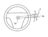
- FIG. 4 is a schematic diagram for explaining a mounting position of the sensor unit 2.
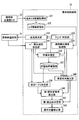
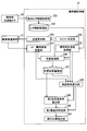
- 4 is a functional block diagram illustrating an example of a schematic configuration of a sensor-side control unit 23.
- FIG. 3 is a functional block diagram illustrating an example of a schematic configuration of a portable side control unit 33 according to Embodiment 1.
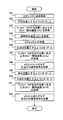
- FIG. 4 is a flowchart illustrating an example of a flow of learning processing in a learning processing unit 336 according to the first embodiment.
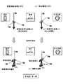
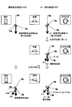
- FIG. 6 is a schematic diagram for explaining the basis for detecting the position of the blinker lever 5 from the lever side acceleration detected by the lever side acceleration sensor 21 and the mobile side acceleration detected by the mobile side acceleration sensor 32.
- FIG. 6 is a schematic diagram for explaining the basis for detecting the position of the blinker lever 5 from the lever side acceleration detected by the lever side acceleration sensor 21 and the mobile side acceleration detected by the mobile side acceleration sensor 32.
- FIG. 6 is a schematic diagram for explaining the basis for detecting the position of the blinker lever 5 from the lever side acceleration detected by the lever side acceleration sensor 21 and the mobile side acceleration detected by the mobile side acceleration sensor 32.
- FIG. 6 is a schematic diagram for explaining the basis for detecting the position of the blinker lever 5 from the lever side acceleration detected by the lever side acceleration sensor 21 and the mobile side acceleration detected by the mobile side acceleration sensor 32.
- FIG. 6 is a schematic diagram for explaining the basis for detecting the position of the blinker lever 5 from the lever side acceleration detected by the lever side acceleration sensor 21 and the mobile side acceleration detected by the mobile side acceleration sensor 32.
- FIG. 6 is a schematic diagram for explaining the basis for detecting the position of the blinker lever 5 from the lever side acceleration detected by the lever side acceleration sensor 21 and the mobile side acceleration detected by the mobile side acceleration sensor 32.
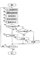
- 6 is a flowchart illustrating an example of a flow of operation position detection related processing in a portable control unit 33 according to the first embodiment.
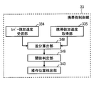
- 6 is a functional block diagram illustrating an example of a schematic configuration of a portable control unit 33 according to Embodiment 2.
- FIG. 12 is a flowchart illustrating an example of a flow of learning processing in a learning processing unit 336 according to the second embodiment. 12 is a flowchart illustrating an example of a flow of operation position detection related processing in a portable control unit 33 according to the second embodiment.
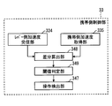
- FIG. 10 is a functional block diagram illustrating an example of a schematic configuration of a portable control unit 33 according to a third embodiment. 14 is a flowchart illustrating an example of a flow of learning processing in a learning processing unit 336 according to the third embodiment. 14 is a flowchart illustrating an example of a flow of an operation detection related process in a portable side control unit 33 according to the third embodiment. It is a schematic diagram for demonstrating the centrifugal force produced by turning of the own vehicle.
- FIG. 14 is a flowchart illustrating an example of a flow of operation position detection related processing in the mobile side control unit 33 in the first in-vehicle device 200 in Modification 4; It is the figure which showed the structure required for description of the modification 7 among the structures with which the portable side control part 33 is provided.
- 16 is a flowchart illustrating an example of a flow of an operation detection related process in a portable side control unit 33 in the first in-vehicle device 200 in Modification 7.
- FIG. 1 is a diagram illustrating an example of a schematic configuration of a vehicle operation detection system 1 to which the present disclosure is applied.
- the vehicle operation detection system 1 is used in a vehicle to detect the position of the winker lever 5, and includes a sensor unit 2 and a portable terminal 3 as shown in FIG.
- a vehicle using the vehicle operation detection system 1 is referred to as a host vehicle.
- the portable terminal 3 corresponds to a vehicle operation detection device, and the blinker lever 5 corresponds to an operation member.
- the sensor unit 2 is attached to the winker lever 5 of the own vehicle.
- the blinker lever 5 is an operation member for turning on a blinker lamp when turning right or left or changing a course and indicating the direction around the turn signal switch, and may be called a turn signal switch or a turn signal lever.
- the winker lever 5 is provided such that the position of a tip portion 5b (see FIG. 2), which is the other end with a fixed end 5a (see FIG. 2) fixed to the vehicle as a fulcrum, is swingable in the lever rotation direction. Yes.
- the direction in which the tip 5b is moved by the rotation of the blinker lever 5 is a direction including a vertical component (that is, a component in the direction of gravitational acceleration).
- the movable range of the blinker lever 5 is provided to be less than several tens of degrees.
- the stationary position where the position of the front end portion 5b of the winker lever 5 does not change even when the driver releases his hand is a neutral position where the operation of turning on the winker lamp is not performed.
- the neutral position corresponds to a non-operating position, and the right lighting position and the left lighting position correspond to a plurality of operation positions.
- the sensor unit 2 is attached to the tip 5b of a stick-like blinker lever 5 extending from the steering column of the vehicle, as shown in FIG.
- the sensor unit 2 may be configured to be detachably fixed to the winker lever 5, but is detachably mounted from the winker lever 5 so that the sensor unit 2 can be used even when the vehicle is changed like car sharing. It is good also as a structure.
- the mobile terminal 3 is a multi-function mobile phone such as a smartphone, for example, and detects acceleration generated in the terminal itself.
- the mobile terminal 3 moves with the own vehicle by being placed in a place where the posture of the own vehicle does not change (hereinafter referred to as a non-posture change place) or fixed by a holder case provided in the non-posture change place. Shall. Therefore, the acceleration generated in the mobile terminal 3 can be identified with the acceleration generated in the own vehicle.
- the sensor unit 2 includes a lever side acceleration sensor 21, a sensor side communication unit 22, and a sensor side control unit 23. It is assumed that the lever-side acceleration sensor 21, the sensor-side communication unit 22, and the sensor-side control unit 23 are supplied with power from a battery built in the sensor unit 2. Moreover, it is good also as a structure which supplies electric power from the power supply outside the sensor unit 2 like a cigarette power supply of a vehicle. A built-in battery may be used from the viewpoints of downsizing the sensor unit 2 and labor of wiring.
- the lever side acceleration sensor 21 is a sensor that detects acceleration.
- the lever side acceleration sensor 21 corresponds to an operation side sensor. Since the sensor unit 2 is attached to the front end portion 5 b of the winker lever 5, the lever side acceleration sensor 21 sequentially detects acceleration generated at the front end portion 5 b of the winker lever 5. For example, it is assumed that the lever side acceleration sensor 21 is a three-axis acceleration sensor that detects acceleration in three axes orthogonal to each other.
- the lever side acceleration sensor 21 detects only the gravitational acceleration corresponding to each of the three types of positions such as the neutral position of the blinker lever 5, the right lighting position, and the left lighting position.
- the tip portion 5b of the winker lever 5 moves in the rotation direction around the fixed end 5a. Therefore, the angle formed by each axis of the lever side acceleration sensor 21 attached to the tip portion 5b of the winker lever 5 and the vertical direction is different in the neutral position, the right lighting position, and the left lighting position. Therefore, the magnitude of the gravitational acceleration acting on each axis of the lever side acceleration sensor 21 when the host vehicle is stopped is different between the neutral position, the right lighting position, and the left lighting position.
- the lever-side acceleration sensor 21 causes the behavior of the host vehicle to change to the gravitational acceleration corresponding to the three types of positions such as the neutral position of the winker lever 5, the right lighting position, and the left lighting position.
- the acceleration with the acceleration component due to the above is added is detected.
- the sensor-side communication unit 22 includes a transmission / reception antenna, and exchanges information with the mobile terminal 3 of the vehicle by performing communication according to the Bluetooth (registered trademark) standard.
- the sensor-side control unit 23 is configured as a normal computer, and includes a well-known CPU, a memory such as a ROM, a RAM, and an EEPROM, an I / O, and a bus line for connecting these configurations (all not shown). Etc.).
- the sensor-side control unit 23 executes various processes by the CPU executing programs stored in advance in the ROM based on various information input from the lever-side acceleration sensor 21 and the sensor-side communication unit 22.
- a part or all of the functions executed by the sensor-side control unit 23 may be configured by hardware using one or a plurality of ICs.
- the sensor-side control unit 23 includes a detection value acquisition unit 231, a detection value storage unit 232, a request reception unit 233, and a detection value transmission processing unit 234.
- the detection value acquisition unit 231 sequentially acquires acceleration detection values sequentially output from the lever-side acceleration sensor 21.
- This detected value is an acceleration vector (hereinafter referred to as lever-side acceleration) composed of acceleration for each axis of the lever-side acceleration sensor 21.
- the detection value acquisition unit 231 stores the acquired lever-side acceleration in the detection value storage unit 232.
- the detection value acquisition unit 231 associates and accumulates the time stamp of the lever side acceleration. Further, the detected value accumulation unit 232 may be configured to erase the older lever side acceleration in order when the allocated memory capacity is exceeded.
- the request receiving unit 233 receives a transmission request, which will be described later, transmitted from the mobile side communication unit 31 of the mobile terminal 3 via the sensor side communication unit 22.
- the detection value transmission processing unit 234 reads the latest multiple lever-side accelerations accumulated in the detection value accumulation unit 232. Then, a moving average of the read lever side accelerations is calculated, and the calculated moving average value is transmitted from the sensor side communication unit 22 as the lever side acceleration of the winker lever 5.
- the detection value transmission processing unit 234 is not limited to the configuration in which the above-described moving average value is transmitted from the sensor-side communication unit 22 as the lever-side acceleration, but the most recent lever side accumulated in the detection value accumulation unit 232
- the acceleration may be transmitted from the sensor side communication unit 22 as the lever side acceleration of the winker lever 5.
- a time stamp corresponding to the lever side acceleration is also given and transmitted.
- a time stamp corresponding to the most recent lever side acceleration stored in the detection value storage unit 232 is added and transmitted. do it.
- the detection value transmission processing unit 234 defaults to not transmit the lever-side acceleration from the sensor-side communication unit 22 except when a transmission request from the portable terminal 3 is met in order to reduce power consumption. To do.
- the mobile terminal 3 detects the acceleration generated in the own terminal, or detects the position of the blinker lever 5 using the acceleration detected by the own terminal and the acceleration detected by the sensor unit 2.
- the portable terminal 3 includes a portable communication unit 31, a portable acceleration sensor 32, and a portable control unit 33.
- the portable communication unit 31 includes a transmission / reception antenna, and exchanges information with the sensor unit 2 of the own vehicle by performing communication according to the Bluetooth standard.
- the configuration in which the communication between the mobile terminal 3 and the sensor unit 2 is performed according to the Bluetooth standard is shown, but the configuration is not necessarily limited thereto.
- it may be configured to perform wireless communication according to short-range wireless communication standards such as ZigBee (registered trademark) or wireless LAN standards such as IEEE 802.11, or may be configured to perform wired communication such as USB communication.
- the mobile-side acceleration sensor 32 is a sensor that is built in the mobile terminal 3 and detects acceleration generated in the mobile terminal 3.
- the mobile-side acceleration sensor 32 is a triaxial acceleration sensor that detects acceleration in three axes that are orthogonal to each other.
- the mobile terminal 3 incorporating the mobile-side acceleration sensor 32 moves with the own vehicle by being placed or fixed at a non-posture change location, so the mobile-side acceleration sensor 32 is generated in the own vehicle. It can be said that acceleration is detected.
- the mobile acceleration sensor 32 corresponds to a fixed sensor. Even if the mobile terminal 3 is placed at a non-posture change point or is fixed, the mobile terminal 3 does not move in the vehicle position when the vehicle is running or stopped. And
- the portable-side acceleration sensor 32 does not move in the vehicle, so that the posture when the portable terminal 3 in the own vehicle is arranged while the own vehicle is stopped. Only the gravitational acceleration corresponding to (that is, the inclination) is detected.
- the mobile-side acceleration sensor 32 is an acceleration obtained by adding an acceleration component due to the behavior of the host vehicle to the gravitational acceleration according to the place where the mobile terminal 3 is disposed in the host vehicle. Will be detected.
- the portable-side control unit 33 is configured as a normal computer, and includes a well-known CPU, a memory such as a ROM, a RAM, and an EEPROM, an I / O, and a bus line for connecting these configurations (all not shown). Etc.).
- the portable side control unit 33 corresponds to a vehicle operation detection unit.
- the portable side control unit 33 executes various processes when the CPU executes programs stored in advance in the ROM based on various information input from the portable side communication unit 31 and the portable side acceleration sensor 32.
- the mobile-side control unit 33 may be configured by hardware using one or a plurality of ICs.
- the mobile side control unit 33 includes a terminal sensor information acquisition unit 331, a sensor information storage unit 332, a transmission request unit 333, a lever side acceleration reception unit 334, a mobile side acceleration acquisition unit 335, and a learning processing unit 336. , A learning result accumulation unit 337, a timing determination unit 338, an assumed vector determination unit 339, an actual variation angle calculation unit 340, a first assumption variation angle calculation unit 341, a first most approximate determination unit 342, and an operation position detection unit 343. ing.
- the sensor information storage unit 332 and the learning result storage unit 337 are electrically rewritable memories such as a RAM and an EEPROM.
- a RAM random access memory
- EEPROM electrically rewritable read-only memory
- the terminal sensor information acquisition unit 331 stores the detected acceleration values sequentially detected by the mobile-side acceleration sensor 32 in the sensor information storage unit 332.
- This detected value is an acceleration vector (hereinafter referred to as a mobile-side acceleration) composed of an acceleration for each axis of the mobile-side acceleration sensor 32.
- the terminal sensor information acquisition unit 331 stores the mobile side acceleration in the sensor information storage unit 332, the mobile side acceleration time stamp is linked and stored.
- the sensor information storage unit 332 may be configured to delete the oldest mobile-side acceleration in order when the allocated memory capacity is exceeded. In addition, it is good also as a structure which erase
- the transmission request unit 333 transmits a transmission request for requesting the sensor unit 2 to transmit the lever side acceleration to the sensor unit 2 via the portable side communication unit 31.
- a transmission request is transmitted from the mobile terminal 3, that is, when a transmission request is made, the sensor unit 2 transmits the lever side acceleration at the lever side acceleration sensor 21 and its time stamp.
- the lever-side acceleration reception unit 334 performs lever-side acceleration reception processing for receiving the lever-side acceleration and the time stamp transmitted from the sensor-side communication unit 22 of the sensor unit 2 via the mobile-side communication unit 31.
- the mobile-side acceleration acquisition unit 335 performs mobile-side acceleration acquisition processing that reads and acquires mobile-side acceleration stored in the sensor information storage unit 332.
- the mobile-side acceleration acquisition unit 335 reads and acquires the mobile-side acceleration with the time stamp that is closest to the time stamp of the lever-side acceleration received by the lever-side acceleration reception unit 334.
- the mobile-side acceleration acquisition unit 335 reads a plurality of mobile-side accelerations including the mobile-side acceleration to which the time stamp closest to the time stamp of the lever-side acceleration received by the lever-side acceleration reception unit 334 is given. Specifically, a plurality of mobile-side accelerations that are traced back in time series from the mobile-side acceleration provided with the time stamp closest to the time stamp of the lever-side acceleration are read.
- the term “plurality” as used herein refers to the same number as the number of samples when the moving average is calculated by the detection value transmission processing unit 234 of the sensor unit 2. Then, the mobile-side acceleration acquisition unit 335 calculates a moving average of the read mobile-side accelerations for a plurality of times, and acquires the calculated moving average value as the mobile-side acceleration.
- the learning process is performed at the start of the use of the vehicle operation detection system 1 such as every time the sensor unit 2 is reattached to the winker lever 5 or every time the location of the mobile terminal 3 is changed in the host vehicle.
- This is an initial setting process that is performed in advance to enable position detection.
- the mobile-side acceleration and the lever-side acceleration when the winker lever 5 is in the neutral position are stored under the same conditions such as when the host vehicle is stopped, and the winker lever 5 is neutral under that condition.
- the shift vector of the lever side acceleration when the position is changed to the left lighting position or the right lighting position is also stored.
- the following description will be given by taking as an example a case where the learning process is performed while the host vehicle is stopped.
- the detection axis of the lever-side acceleration sensor 21 included in the sensor unit 2 and the detection axis of the mobile-side acceleration sensor 32 included in the mobile terminal 3 may not coincide with each other. Good.
- the flowchart of FIG. 5 may be configured to start when a user operation indicating that the above-described initial setting is started is received by an operation input unit (not illustrated) of the mobile terminal 3.
- the transmission request unit 333 makes a transmission request so that the lever side acceleration detected by the sensor unit 2 can be received.
- the lever-side acceleration detected by the lever-side acceleration sensor 21 of the sensor unit 2 is acquired after elapse of a predetermined period from the guidance in S2, out of the lever-side acceleration received by the lever-side acceleration receiving unit 334. That is, the lever side acceleration when the winker lever 5 is in the neutral position is acquired.
- the lever side acceleration detected after the elapse of a predetermined period from the guidance in S2 may be determined using a time stamp.
- the mobile-side acceleration acquired by the mobile-side acceleration acquisition unit 335 is acquired.
- the mobile-side acceleration having the time stamp closest to the time stamp of the lever-side acceleration acquired in S3 is acquired.
- the lever-side acceleration acquired in S3 when the winker lever 5 is in the neutral position and the mobile-side acceleration acquired in S4 are stored in the learning result accumulation unit 337.
- the lever-side acceleration (a1s in FIGS. 6 and 7) obtained in S3 when the winker lever 5 is in the neutral position is hereinafter referred to as the lever-side reference acceleration (a1s), and the mobile-side acceleration obtained in S4 (FIGS. 6 and 7). 7 a2s) is hereinafter referred to as mobile-side reference acceleration (a2s). Since the lever side acceleration and the mobile side acceleration are acceleration vectors as described above, the lever side reference acceleration (a1s) corresponds to the operation side reference acceleration vector, and the mobile side reference acceleration (a2s) corresponds to the fixed side reference acceleration vector. To do.
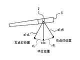
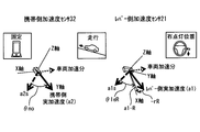
- FIG. 6 shows the mobile-side reference acceleration (a2s) detected by the mobile-side acceleration sensor 32 of the mobile terminal 3 while the host vehicle is stopped, and the lever-side acceleration sensor 21 of the sensor unit 2 while the host vehicle is stopped.
- It is a schematic diagram which shows the lever side acceleration (a1s, a1sL, a1sR) according to the position of the turn signal lever 5.
- the lever side acceleration for each position of the winker lever 5 the aforementioned lever side reference acceleration (a1s) when the winker lever 5 is in the neutral position, and lever side acceleration (a1sL) when the winker lever 5 is in the left lighting position.
- lever side acceleration (a1sR) when the winker lever 5 is in the right lighting position.
- any of the mobile side reference acceleration (a2s), the lever side reference acceleration (a1s), the lever side acceleration (a1sL), and the lever side acceleration (a1sR) is gravitational acceleration. It has become.
- FIG. 7 shows the relationship between the lever-side reference acceleration (a1s), lever-side acceleration (a1sL), and lever-side acceleration (a1sR) vectors when the winker levers 5 at the respective positions in FIG. It is a schematic diagram.
- the angle of the blinker lever 5 is different at the neutral position, the left lighting position, and the right lighting position. That is, the angle of the sensor unit 2 with respect to the vertically downward direction is different at the neutral position, the left lighting position, and the right lighting position. Therefore, the lever-side reference acceleration (a1s), lever-side acceleration (a1sL), and lever-side acceleration (a1sR) vectors shown in FIG. 7 have different directions.
- a transition vector (rL in FIG. 7) corresponding to the transition is stored in the learning result accumulation unit 337. This transition vector is hereinafter referred to as a left lighting position transition vector (rL).
- the winker lever is calculated from the lever side acceleration detected by the lever side acceleration sensor 21 of the sensor unit 2 and the mobile side acceleration detected by the mobile side acceleration sensor 32 of the mobile terminal 3.
- the reason why the position 5 can be detected will be described.
- the description will be made with reference to the inclination and running state of the vehicle and the position of the blinker lever 5 (that is, the neutral position) when the learning process is performed.
- the lever-side acceleration detected by the lever-side acceleration sensor 21 after the learning process is called a lever-side actual acceleration
- the portable-side acceleration detected by the portable-side acceleration sensor 32 after the learning process is called a portable-side actual acceleration.
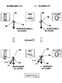
- 8 to 13 are diagrams showing examples of the lever side acceleration and the mobile side acceleration when the conditions change variously from the conditions when the learning process is performed. 8 to 13, it is assumed that the mobile terminal 3 is always fixed to the host vehicle, and the lever-side acceleration sensor 21 of the sensor unit 2 attached to the winker lever 5 and the mobile-side acceleration sensor 32 of the mobile terminal 3 are used. And the three detection axes do not coincide with each other.
- the mobile-side actual acceleration detected by the mobile-side acceleration sensor 32 (see the solid line arrow in the figure) and the lever-side acceleration sensor when the inclination of the vehicle changes from the conditions at the time of the learning process.
- 21 schematically shows the shift from the actual acceleration on the lever side (see the solid line arrow in the figure) detected at 21.
- the upper part of FIG. 8 shows conditions when the learning process is performed, and the lower part shows conditions after the inclination of the vehicle changes.
- the posture of the rear mobile terminal 3 remains fixed, and the position of the blinker lever 5 remains in the neutral position. Only the inclination of the vehicle is different.
- the lever-side actual acceleration is an acceleration whose angle is shifted from the lever-side reference acceleration (a1s) by an amount corresponding to the inclination of the own vehicle ( ⁇ le1 in FIG. 8).
- the angle is shifted from the portable side reference acceleration (a2s) by the amount corresponding to the inclination of the vehicle ( ⁇ mo1 in FIG. 8).
- le in ⁇ le1 is an abbreviation for level
- mo in ⁇ mo1 is an abbreviation for mobile. The same applies to “le” and “mo” used hereinafter.
- the winker lever 5 is in the neutral position, and the position of the winker lever 5 is not changed, as in the condition when the learning process is performed. Since the host vehicle is stationary and neither the mobile terminal 3 nor the sensor unit 2 has changed its attitude to the host vehicle, the actual change angle of the lever side actual acceleration from the lever side reference acceleration (a1s) due to the tilt of the host vehicle. ( ⁇ le1) should be equal to the actual change angle ( ⁇ mo1) of the mobile-side actual acceleration from the mobile-side reference acceleration (a2s) due to the inclination of the host vehicle.
- the winker lever 5 is in the neutral position and the position of the winker lever 5 is not changed, similar to the conditions when the learning process is performed.
- the actual change angle ( ⁇ le2) of the lever side actual acceleration from the lever side reference acceleration (a1s) generated by the traveling of the host vehicle is It should be equal to the actual change angle ( ⁇ mo2) of the mobile-side actual acceleration from the mobile-side reference acceleration (a2s) generated by traveling.
- the actual change angle (referred to as ⁇ le) of the actual acceleration on the lever side from the lever-side reference acceleration (a1s) and the actual actual acceleration on the portable side from the portable-side reference acceleration (a2s) generated by the traveling of the vehicle.
- transition angle (referred to as ⁇ mo) approximates, it can be said that the winker lever 5 is in the neutral position.
- the mobile-side actual acceleration detected by the mobile-side acceleration sensor 32 is the mobile-side reference acceleration ( a2s) is an acceleration whose angle has changed ( ⁇ mo1 in FIG. 10).
- the actual lever-side acceleration detected by the lever-side acceleration sensor 21 is a change (that is, ⁇ le3) in which the position of the winker lever 5 is changed to the right lighting position from the lever-side reference acceleration (a1s), and the own vehicle.
- the angle is changed ( ⁇ le4 in FIG. 10) by an amount corresponding to a change corresponding to the inclination ( ⁇ le1 described above).
- the actual mobile-side acceleration detected by the mobile-side acceleration sensor 32 is further increased by the amount of acceleration generated by the traveling of the own vehicle. Becomes the shifted acceleration ( ⁇ mo2 in FIG. 11). That is, the mobile-side actual acceleration is obtained from the mobile-side reference acceleration (a2s) with the change of the inclination of the own vehicle ( ⁇ mo1) and the change of the acceleration caused by the travel of the vehicle ( ⁇ mo2).
- the lever-side actual acceleration detected by the lever-side acceleration sensor 21 is an acceleration whose angle is further shifted ( ⁇ le2 in FIG. 11) by the acceleration generated by the traveling of the host vehicle. That is, from the lever-side reference acceleration (a1s), a change corresponding to the turn-on position of the blinker lever 5 ( ⁇ le3 in FIG. 10), a change corresponding to the inclination of the own vehicle ( ⁇ le1), and an acceleration generated by the traveling of the own vehicle.
- the actual lever side acceleration with a minute shift ( ⁇ le2) is obtained.
- the acceleration detected by the mobile-side acceleration sensor 32 and the lever-side acceleration sensor 21 corresponds to the amount that the blinker lever 5 is in the right lighting position. There is only a difference due to the transition ( ⁇ le3). Therefore, whether or not the blinker lever 5 is in the right lighting position can be detected depending on whether there is this difference.
- the right lighting position transition vector (rR) when the winker lever 5 moves from the neutral position to the right lighting position is returned from the lever side actual acceleration (hereinafter referred to as a1) that is the observed value.
- the acceleration (hereinafter referred to as a1-R) obtained by returning this right lighting position transition vector (rR) from the lever side actual acceleration (a1) is that if the winker lever 5 is at the right lighting position, the winker lever 5
- the acceleration component corresponding to the transition corresponding to the lighting position is removed.
- the assumed transition angle (hereinafter referred to as ⁇ leR) of the acceleration (a1-R) obtained by returning the right lighting position transition vector (rR) from the lever-side actual acceleration (a1) from the lever-side reference acceleration (a1s) is
- the actual change angle ( ⁇ mo) from the mobile-side reference acceleration (a2s) to the mobile-side actual acceleration should be equal.
- the assumed transition angle (hereinafter referred to as ⁇ leR) from the lever-side reference acceleration (a1s) of the acceleration obtained by returning the right lighting position change vector (the aforementioned rR) from the lever-side actual acceleration is the mobile-side reference acceleration (hereinafter referred to as ⁇ leR).
- ⁇ leR the mobile-side reference acceleration
- the hypothetical transition angle ( ⁇ leR) is hereinafter referred to as a right position assumed transition angle ( ⁇ leR).
- the actual change angle ( ⁇ le) from the lever-side reference acceleration (a1s) to the lever-side actual acceleration is equal to the actual change angle ( ⁇ mo) from the portable-side reference acceleration (a2s) to the portable-side actual acceleration.
- the winker lever 5 is in the neutral position.
- the timing determination unit 338 determines that it is necessary to detect the position of the blinker lever 5.
- the timing determination unit 338 for example, when the detection of the position of the winker lever 5 is necessary for driving support, the timing at which the position of the winker lever 5 needs to be detected is set as a state in which the preparation for driving support is to be prepared. Is determined.
- the state where preparation for driving assistance should be prepared includes the case where there are other vehicles around the vehicle and the case near the intersection.
- the timing determination unit 338 may also be configured to determine a timing at which detection of the position of the blinker lever 5 is no longer necessary, and to issue a stop request for stopping transmission of lever side acceleration from the sensor unit 2.
- the lever-side acceleration receiving unit 334 performs the lever-side acceleration receiving process described above, receives the lever-side acceleration (that is, actual lever-side acceleration) transmitted from the sensor unit 2, and proceeds to S22.
- the mobile-side acceleration acquisition unit 335 performs the mobile-side acceleration acquisition process described above, acquires the mobile-side acceleration detected by the mobile-side acceleration sensor 32 of the terminal itself, and proceeds to S23.
- an assumed vector is determined from the lever-side actual acceleration received in the lever-side acceleration receiving process and the left lighting position transition vector (rL) and right lighting position transition vector (rR) stored in the learning result accumulation unit 337.
- the unit 339 performs an assumed vector determination process.
- a left position shift vector (a1-L) is determined by shifting the actually measured acceleration on the lever side by the reverse direction (-rL) of the left lighting position transition vector (rL) (see FIG. 13). Further, in this hypothetical vector determination process, a right position shift vector (a1-R) obtained by shifting the lever-side measured acceleration by the reverse direction (-rR) of the right lighting position transition vector (rR) is also determined (see FIG. 12). ).
- the actual change angle calculation unit 340 performs the actual change angle ( ⁇ le) formed by the lever side reference acceleration (a1s) stored in the learning result accumulation unit 337 and the lever side actual acceleration received in the lever side acceleration reception process. ) Is calculated.
- the actual change angle ( ⁇ le) here is an absolute value without a positive or negative sign.
- the actual change angle ( ⁇ mo) formed by the mobile side reference acceleration (a2s) stored in the learning result accumulation unit 337 and the mobile side actual acceleration acquired in the mobile side acceleration acquisition process. ) Is calculated.
- the actual change angle ( ⁇ mo) here is an absolute value without a positive or negative sign.
- the first assumed transition angle calculation unit 341 performs the left position assumed transition angle ( ⁇ leL) formed by the lever side reference acceleration (a1s) and the left position shift vector (a1-L) determined in the assumed vector determination process. ) Is calculated (see FIG. 13).
- a right position assumed transition angle ( ⁇ leR) formed by the lever side reference acceleration and the right position shift vector (a1-R) determined in the assumed vector determination process is calculated.
- the left position assumed transition angle ( ⁇ leL) and the right position assumed transition angle ( ⁇ leR) are, for example, absolute values without a positive or negative sign.
- the left position shift vector (a1-L) and the right position shift vector (a1-R) correspond to hypothetical vectors.
- the left-side assumed transition angle ( ⁇ leL) and the right-position assumed transition angle ( ⁇ leR) correspond to the assumed transition angle calculated by the first assumed transition angle calculation unit.
- the first most approximate determination unit 342 uses the actual change angle ( ⁇ le) calculated by the actual change angle calculation process, the left position assumed change angle ( ⁇ leL) calculated by the first assumed change angle calculation process, and the right position use. Of the assumed transition angle ( ⁇ leR), a first most approximate determination process is performed for determining a value closest to the actual transition angle ( ⁇ mo) calculated in the actual transition angle calculation process.
- the operation position detector 343 detects the position of the blinker lever 5 as the left lighting position. In S31, the operation position detector 343 detects the position of the blinker lever 5 as the right lighting position.
- the left lighting position transition vector (rL) and the right lighting position transition vector (rR) are stored in the learning result storage unit 337 in advance during the learning process, and the behavior of the vehicle is different from that in the operation position detection related process. Will not necessarily match, so there will be some error from the actual situation. However, in this embodiment, among the actual change angle ( ⁇ le), the left position assumed change angle ( ⁇ leL), and the right position assumed change angle ( ⁇ leR), the value closest to the actual change angle ( ⁇ mo) is obtained. Since the determination is made, it is possible to detect the position of the winker lever 5 with high accuracy while suppressing the influence of the error.
- both the lever-side acceleration sensor 21 and the portable-side acceleration sensor 32 are triaxial acceleration sensors that detect at least acceleration in the direction of gravitational acceleration, the lever-side acceleration sensor 21 and the portable-type acceleration sensor 21 are carried during the movement of the host vehicle.
- the acceleration as a detection result of the side acceleration sensor 32 includes not only gravitational acceleration but also an acceleration component resulting from the behavior of the vehicle.
- the position of the blinker lever 5 can be detected with higher accuracy.
- the acceleration detected by the lever-side acceleration sensor 21 and the mobile-side acceleration sensor 32 is not a comparison target, but the amount of change from the reference acceleration learned under a certain condition ( That is, the actual change angle ( ⁇ mo), the actual change angle ( ⁇ le), the left position assumed change angle ( ⁇ leL), and the right position assumed change angle ( ⁇ leR) are to be compared. It is possible to make a comparison even if the axes of the mobile phone side acceleration sensor 32 and the mobile side acceleration sensor 32 do not coincide with each other. In order to make the detection axes of the lever side acceleration sensor 21 and the mobile side acceleration sensor 32 coincide, There is an advantage that it does not require time and effort to match the orientation of the portable terminal 3.
- the vehicle operation detection system 1 uses a left lighting position transition angle and a right lighting position transition angle, which will be described later, instead of the left lighting position transition vector (rL) and the right lighting position transition vector (rR) described above. Except for this point, the present embodiment is the same as the vehicle operation detection system 1 of the first embodiment.
- the mobile side control unit 33 includes a terminal sensor information acquisition unit 331, a sensor information storage unit 332, a transmission request unit 333, a lever side acceleration reception unit 334, a mobile side acceleration acquisition unit 335, and a learning processing unit 336. , A learning result accumulation unit 337, a timing determination unit 338, an actual change angle calculation unit 340, an operation position detection unit 343, a second assumed change angle calculation unit 344, and a second closest approximation determination unit 345.
- the learning processing unit 336 according to the second embodiment performs the following learning process.
- the learning process in the learning processing unit 336 according to the second embodiment will be described with reference to the flowchart of FIG.
- the processing from S41 to S47 is the same as the processing from S1 to S7 described above.
- the angle (hereinafter referred to as the angle between the lever-side reference acceleration (a1s) when the winker lever 5 is in the neutral position and the lever-side acceleration (a1sL) when the winker lever 5 is in the left lighting position, acquired in S43).
- Left lighting position transition angle is stored in the learning result accumulation unit 337.
- the processing from S49 to S51 is the same as the processing from S9 to S11 described above.
- the angle (hereinafter referred to as the angle between the lever-side reference acceleration (a1s) when the winker lever 5 is in the neutral position and the lever-side acceleration (a1sL) when the winker lever 5 is in the left lighting position, acquired in S43).
- the right lighting position transition angle is stored in the learning result accumulation unit 337. For example, a negative sign is attached in the clockwise direction with respect to the vector of the lever side reference acceleration (a1s), and a positive sign is attached in the counterclockwise direction.
- the lever side actual acceleration is shifted by a shift vector (that is, rL or rR) when the position of the blinker lever 5 is at the left lighting position or the right lighting position. It was.
- the position of the blinker lever 5 is determined as the left lighting position or the right lighting position from the actual change angle ( ⁇ le) of the lever side actual acceleration from the lever side reference acceleration (a1s). The difference is that a process of subtracting only the transition angle (that is, the left lighting position transition angle or the right lighting position transition angle) is performed.
- the left lighting position transition angle and the right lighting position transition angle correspond to the position-specific transition angles.
- the processing from S61 to S62 is the same as the processing from S21 to S22 in the first embodiment.
- the actual change angle calculation unit 340 receives the lever-side reference acceleration (a1s) stored in the learning result accumulation unit 337 and the lever-side acceleration reception process in the same manner as S24 in the first embodiment.
- An actual change angle calculation process for calculating an actual change angle ( ⁇ le) formed with the lever side actual acceleration is performed.
- a negative sign is attached in the clockwise direction with reference to the lever side reference acceleration (a1s), and a positive sign is attached in the counterclockwise direction.
- a configuration is shown in which a negative sign is added in the clockwise direction and a positive sign is added in the counterclockwise direction, but the configuration is not limited thereto.
- a negative sign may be attached in the case of counterclockwise rotation
- a positive sign may be attached in the case of clockwise rotation.
- the actual change angle calculation process of S63 the actual value formed by the vector of the mobile side reference acceleration (a2s) stored in the learning result accumulation unit 337 and the vector of the mobile side real acceleration acquired in the mobile side acceleration acquisition process.
- a transition angle ( ⁇ mo) is calculated.
- the actual change angle ( ⁇ mo) here may be an absolute value without a positive or negative sign, as in the first embodiment.
- the second hypothetical change angle calculation unit 344 uses the actual change angle ( ⁇ le) calculated in the actual change angle calculation process, and the angle corresponding to the reverse sign of the left lighting position change angle stored in the learning result accumulation unit 337.
- a second hypothetical transition angle calculation process for calculating a hypothetical transition angle ( ⁇ leL ⁇ ) obtained by subtracting only this is performed.
- a hypothetical transition angle ( ⁇ leR ⁇ ) obtained by subtracting only is calculated.
- the change angle ( ⁇ leL ⁇ ) and the change angle ( ⁇ leR ⁇ ) correspond to the assumed change angle calculated by the second assumed change angle calculation unit.
- the transition angle ( ⁇ leL ⁇ ) is referred to as a left position assumed transition angle ( ⁇ leL ⁇ )
- the transition angle ( ⁇ leR ⁇ ) is referred to as a right position assumed transition angle ( ⁇ leR ⁇ ).
- the second most approximate determination unit 345 uses the actual change angle ( ⁇ le) calculated in the actual change angle calculation process, the left position assumed change angle ( ⁇ leL ⁇ ) calculated in the second assumed change angle calculation process, and the right position use. Among the absolute values of the assumed transition angle ( ⁇ leR ⁇ ), the one having the closest value to the absolute value of the actual transition angle ( ⁇ mo) calculated by the actual transition angle calculation process is determined.
- the operation position detector 343 detects the position of the blinker lever 5 as the left lighting position.
- the operation position detector 343 detects the position of the blinker lever 5 as the right lighting position.
- the process of S71 is the same as S32 of the first embodiment.
- the angle ( ⁇ leR ⁇ ) is not obtained by returning the shift vector when the left lighting position or the right lighting position is assumed, but is obtained by subtracting the left lighting position transition angle or the right lighting position transition angle.
- the acceleration direction by the traveling of the host vehicle is not on the rotation plane of the tilt of the host vehicle, and the mobile side acceleration sensor 32 and the lever
- the detection axes of the side acceleration sensor 21 are deviated from each other, the acceleration component generated by the traveling of the own vehicle, the acceleration component according to the inclination of the own vehicle, and the winker lever 5 detected by the lever side acceleration sensor 21.
- the acceleration component according to the position cannot be expressed on the same plane. Therefore, the calculation accuracy of the transition angle between the acceleration and the lever-side reference acceleration (a1s) when the position of the blinker lever 5 is in the left lighting position or the right lighting position is inferior to the configuration of the first embodiment.
- the actual transition angle ( ⁇ le) is most approximate to any of the actual transition angle ( ⁇ mo), the left lighting position transition angle ( ⁇ leL ⁇ ), and the right lighting position transition angle ( ⁇ leR ⁇ ). Since the position of the winker lever 5 is detected depending on whether or not the accuracy of the left lighting position transition angle ( ⁇ leL ⁇ ) and the right lighting position transition angle ( ⁇ leR ⁇ ) is inferior, the position of the winker lever 5 is detected without error. It is possible. Therefore, the position of the blinker lever 5 can be detected with high accuracy also by the configuration of the second embodiment.
- the acceleration detected by the lever-side acceleration sensor 21 and the mobile-side acceleration sensor 32 is not a comparison target, but the amount of change from the reference acceleration learned under a certain condition ( That is, the actual change angle ( ⁇ mo), the actual change angle ( ⁇ le), the left lighting position change angle ( ⁇ leL ⁇ ), and the right lighting position change angle ( ⁇ leR ⁇ )) are to be compared. Therefore, even if the lever-side acceleration sensor 21 and the mobile-side acceleration sensor 32 do not coincide with each other, it is possible to make a comparison, and the lever-side acceleration sensor 21 and the mobile-side acceleration sensor 32 coincide with each other. Therefore, there is an advantage that it does not require the trouble of adjusting the orientation of the sensor unit 2 or the portable terminal 3.
- the sensor unit 2 is attached to an operation member whose operation position changes in multiple steps only from the reference position in the same direction, and the lever side acceleration sensor 21 and the mobile side acceleration sensor 32 are provided.
- the actual transition angle ( ⁇ le), the left lighting position transition angle ( ⁇ leL ⁇ ), and the right lighting position transition angle ( ⁇ leR ⁇ ) are handled as unsigned absolute values. It is good also as a structure.
- the vehicle operation detection system 1 does not detect the position of the winker lever 5 but detects the presence / absence of the operation of the winker lever 5. It is the same.
- the lever side acceleration sensor 21 and the portable side acceleration sensor 32 of the third embodiment are the same as the lever side acceleration sensor 21 and the portable side acceleration sensor 32 of the first embodiment.
- the mobile side control unit 33 includes a terminal sensor information acquisition unit 331, a sensor information storage unit 332, a transmission request unit 333, a lever side acceleration reception unit 334, a mobile side acceleration acquisition unit 335, a learning process.
- the learning processing unit 336 according to the third embodiment performs the following learning process.
- the learning process in the learning processing unit 336 according to the third embodiment will be described with reference to the flowchart of FIG.
- the processing from S81 to S85 is the same as the processing from S1 to S5 in the first embodiment.
- Embodiment 3 ⁇ Operation Detection Related Processing in Embodiment 3>
- operation detection-related processing processing related to detection of operation of the blinker lever 5 in the mobile-side control unit 33 of the mobile terminal 3 in Embodiment 3 (hereinafter, operation detection-related processing) will be described.
- the flowchart of FIG. 20 is also configured to start when the above-described learning process has been performed and a transmission request is made from the transmission request unit 333, as in the flowcharts of FIG. 14 and FIG. That's fine.
- the processing from S91 to S92 is the same as the processing from S21 to S22 in the first embodiment.
- the actual change angle calculation unit 340 performs the actual change angle calculation process in the same manner as in S24 of the first embodiment.
- the coincidence determination unit 346 determines whether or not the actual change angle ( ⁇ le) calculated in the actual change angle calculation process matches the actual change angle ( ⁇ mo) calculated in the actual change angle calculation process. Process. It should be noted that when the actual change angle ( ⁇ le) and the actual change angle ( ⁇ mo) are the same value, it may be determined that they match, or the difference between the actual change angle ( ⁇ le) and the actual change angle ( ⁇ mo) is acceptable. It is good also as a structure which determines with matching, when is below a predetermined value.
- both the lever-side acceleration sensor 21 and the portable-side acceleration sensor 32 are triaxial acceleration sensors that detect at least acceleration in the direction of gravitational acceleration, the lever-side acceleration sensor 21 and the portable-type acceleration sensor 21 are carried during the movement of the host vehicle.
- the acceleration as a detection result of the side acceleration sensor 32 includes not only gravitational acceleration but also an acceleration component resulting from the behavior of the vehicle. Therefore, by comparing the detection result of the mobile side acceleration sensor 32 of the mobile terminal 3 placed or fixed on the vehicle with the object of comparison, the acceleration component caused by the behavior of the host vehicle is reduced, and the winker lever 5 is neutral. It is possible to determine the difference in acceleration between the position and other positions. Therefore, it is possible to detect the presence / absence of the operation of the blinker lever 5 with higher accuracy.
- ⁇ Modification 3> In the configuration of the third embodiment, the case where the winker lever 5 is in the left lighting position or the right lighting position is not considered, and only the case where the winker lever 5 is in the neutral position is considered. When the blinker lever 5 moves from the neutral position to the left lighting position or the right lighting position, since the transition vector cannot be expressed on one plane, the blinker lever 5 is at the left lighting position or the right lighting position.
- the triaxial lever side acceleration sensor 21 is required. However, in the third embodiment, it is not necessary to consider the case where the winker lever 5 is in the left lighting position or the right lighting position. For example, the configuration using the biaxial lever side acceleration sensor 21 that can detect at least the gravitational acceleration direction. It is good.
- the two detection axes of the lever-side acceleration sensor 21 and the portable side are provided so that the actual change angle ( ⁇ le) and the actual change angle ( ⁇ mo) can be compared. It is necessary to match the two detection axes of the acceleration sensor 32.
- the actual change angle ( ⁇ mo) of the mobile-side actual acceleration from the mobile-side reference acceleration (a2s) should be equal.
- the lever side actual sensor 21 detects the actual lever side acceleration detected by the difference in centrifugal force as shown in FIG.
- the vector shift between the acceleration and the mobile-side actual acceleration detected by the mobile-side acceleration sensor 32 increases.
- the winker lever 5 cannot be detected as the neutral position even though the winker lever 5 is in the neutral position.
- the vehicle operation detection system 1 according to Modification 4 is partially different in that the difference calculation unit 348 and the threshold determination unit 349 are further provided in the portable side control unit 33, and the operation position detection unit 343 and the operation detection unit 347 are partially processed. Except for this point, it is the same as the vehicle operation detection system 1 of the first to third embodiments.
- the mobile-side control unit 33 in Modification 4 further includes a difference calculation unit 348 and a threshold determination unit 349 in addition to the configuration described in the first embodiment.
- the difference calculation unit 348 calculates the absolute value of the lever side acceleration and the absolute value of the mobile side acceleration from the lever side acceleration received by the lever side acceleration reception unit 334 and the mobile side acceleration acquired by the mobile side acceleration acquisition unit 335. Difference (hereinafter, absolute value difference) is calculated. This absolute value difference corresponds to the magnitude of vector deviation between the lever-side actual acceleration detected by the lever-side acceleration sensor 21 and the portable-side actual acceleration detected by the portable-side acceleration sensor 32.
- the threshold value determination unit 349 determines whether the absolute value difference calculated by the difference calculation unit 348 is equal to or greater than the threshold value, and outputs the determination result to the operation position detection unit 343.
- the threshold value referred to here is a value of an absolute value difference that is considered to decrease the detection accuracy of the position of the blinker lever 5, and is a value that can be arbitrarily set.
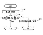
- the difference calculation unit 348 calculates the absolute value of the lever side acceleration and the absolute value of the mobile side acceleration from the lever side acceleration received in S21 and the mobile side acceleration acquired in S22. The absolute value difference is calculated.
- the threshold determination unit 349 determines whether the absolute value difference calculated in S22a is equal to or greater than the threshold. If it is determined that the threshold value is exceeded (YES in S22b), the process proceeds to S23, and the position of the blinker lever 5 is detected according to the subsequent processing. On the other hand, when it determines with less than a threshold value (it is NO at S22b), it moves to S22c.
- the operation position detection unit 343 sets the position of the winker lever 5 detected in the previous operation position detection related process as the position of the winker lever 5 detected in the current operation position detection related process, and proceeds to S32.
- the process of S22c can be paraphrased as a process of maintaining the detection result of the position of the winker lever 5 detected in the latest operation position detection related process determined by the threshold determination unit 349 as being less than the threshold.
- the absolute value difference between the lever-side acceleration and the mobile-side acceleration is equal to or greater than the threshold value and the detection accuracy of the position of the blinker lever 5 is considered to be reduced.
- ⁇ Modification 5> when the threshold value determination unit 349 determines that the absolute value difference is equal to or larger than the threshold value, the detection of the position of the winker lever 5 detected in the latest operation position detection related process in which the absolute value difference is determined to be less than the threshold value.
- the configuration in which the operation position detection unit 343 maintains the result is shown, the configuration is not necessarily limited thereto.
- the actual change angle ( ⁇ mo) and the actual change angle ( ⁇ mo) calculated in the actual change angle calculation process of S24 in the most recent operation position detection related process in which the absolute value difference is determined to be less than the threshold value, and the first of S25 The left position assumed transition angle ( ⁇ leL) and the right position assumed transition angle ( ⁇ leR) calculated by the assumed transition angle calculation processing may be maintained.
- the processes of S26 to S31 are performed using the maintained actual change angle ( ⁇ mo), actual change angle ( ⁇ mo), left position assumed change angle ( ⁇ leL), and right position assumed change angle ( ⁇ leR). And the position of the winker lever 5 is detected.
- ( ⁇ leL) and the assumed shift angle for the right position ( ⁇ leR) are values used for detection when the detection accuracy of the position of the blinker lever 5 is not lowered. Therefore, if this value is used, the possibility of erroneous detection of the position of the blinker lever 5 is low.
- the absolute value difference between the lever side acceleration and the mobile side acceleration is greater than or equal to the threshold value, and the absolute value difference is less than the threshold value in a situation where the detection accuracy of the position of the blinker lever 5 is considered to decrease.
- Modification 6 a configuration that adopts Modification 4 in Embodiment 2 (hereinafter, Modification 6) may be employed.
- the sixth modification includes the configuration illustrated in FIG. 23, and when the threshold value determination unit 349 determines that the absolute value difference is equal to or greater than the threshold value, The operation position detection unit 343 may maintain the detection result of the position of the winker lever 5 detected in the operation position detection related process. Further, the operation position detection related process in the modified example 6 may be configured to add the same process as the process of S22a to S22c after the process of S62 in the flowchart of FIG.
- the operation position detection related processing for the time when the absolute value difference is determined to be less than the threshold value since the detection result of the position of the winker lever 5 detected in step 1 is maintained, it is possible to prevent the position of the winker lever 5 from being erroneously detected.
- Modification 7 a configuration that adopts Modification 4 in Embodiment 3 (hereinafter, Modification 7) may be employed.
- Modification 7 will be described with reference to FIG. In FIG. 25, the structure required for description of the modification 7 is shown among the structures with which the portable side control part 33 is provided.
- the mobile-side control unit 33 in Modification 7 further includes a difference calculation unit 348 and a threshold determination unit 349 in addition to the configuration described in the first embodiment. Since the difference calculation unit 348 and the threshold determination unit 349 are the same as those described in the fourth modification, detailed description thereof is omitted.
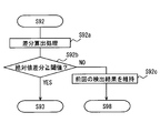
- the flowchart of FIG. 26 is obtained by adding the processes of S92a to S92c after the process of S92 in the flowchart of FIG. 20, and extracting the added process parts of S92a to S92c.
- the difference calculation unit 348 calculates the absolute value of the lever side acceleration and the absolute value of the mobile side acceleration from the lever side acceleration received in S91 and the mobile side acceleration acquired in S92. The absolute value difference is calculated.
- the threshold determination unit 349 determines whether the absolute value difference calculated in S92a is equal to or greater than the threshold. If it is determined that the threshold value is exceeded (YES in S92b), the process proceeds to S93, and whether the blinker lever 5 is operated or not (that is, whether there is an operation) is detected according to the subsequent processing. On the other hand, when it determines with less than a threshold value (it is NO at S92b), it moves to S92c.
- the operation detection unit 347 uses the detection result of the presence / absence of the winker lever 5 detected in the previous operation detection related process as the detection result of the presence / absence of the operation of the winker lever 5 detected in the current operation detection related process. Move on. According to the flowchart of FIG. 26, only the detection result of the presence / absence of the operation detected in the operation detection related process that is determined to be less than the threshold by the threshold determination unit 349 is the detection result of the presence / absence of the operation. Therefore, the process of S92c can be paraphrased as a process of maintaining the detection result of the presence / absence of the operation detected in the latest operation detection related process determined by the threshold determination unit 349 as being less than the threshold.
- the absolute value difference between the lever-side acceleration and the mobile-side acceleration is equal to or greater than the threshold value and the detection accuracy of the presence / absence of the operation of the blinker lever 5 is considered to decrease, the absolute value difference
- the absolute value difference By maintaining the detection result of the presence / absence of the operation of the winker lever 5 detected in the operation detection related process when it is determined that is less than the threshold value, it is possible to prevent erroneous detection of the presence / absence of the operation of the winker lever 5.
- ⁇ Modification 8> For the modified example 6, the actual change angle ( ⁇ mo) and the actual change angle ( ⁇ mo) calculated in the actual change angle calculation process of S63 in the most recent operation position detection related process in which the absolute value difference is determined to be less than the threshold value, and S64 The left position assumed transition angle ( ⁇ leL ⁇ ) and the right position assumed transition angle ( ⁇ leR ⁇ ) calculated in the first assumption transition angle calculation process may be maintained. In this case, the processes of S65 to S70 are performed using the maintained actual change angle ( ⁇ mo), actual change angle ( ⁇ mo), left position assumed change angle ( ⁇ leL ⁇ ), and right position assumed change angle ( ⁇ leR ⁇ ). And the position of the winker lever 5 is detected.
- the actual change angle calculation process and the second change in the operation position detection related process of the time when the absolute value difference is determined to be less than the threshold value Since the value calculated by the assumed transition angle calculation process is maintained, the position of the blinker lever 5 can be prevented from being erroneously detected as in the fifth modification.
- ⁇ Modification 9> the actual change angle ( ⁇ mo) and the actual change angle ( ⁇ mo) calculated in the actual change angle calculation process of S93 in the operation detection related process of the most recent time when the absolute value difference is determined to be less than the threshold value are maintained. It is good. In this case, processing of S94 to S97 is performed using the maintained actual change angle ( ⁇ mo) and actual change angle ( ⁇ mo), and the presence / absence of operation of the blinker lever 5 is detected.
- the actual change angle ( ⁇ mo) and the actual change angle ( ⁇ mo) calculated by the actual change angle calculation process when the absolute value difference is determined to be less than the threshold value does not decrease the detection accuracy of the blinker lever 5 operation. It is the value used for the detection of time. Therefore, if this value is used, the possibility of erroneous detection of the presence / absence of operation of the blinker lever 5 is low.
- the absolute value difference between the lever-side acceleration and the mobile-side acceleration is greater than or equal to the threshold value, and the absolute value difference is considered to be the threshold value under the condition that the detection accuracy of the presence / absence of the operation of the blinker lever 5 is considered to be lowered.
- ⁇ Modification 12> the configuration in which the acceleration generated according to the position of the winker lever 5 is detected by the sensor unit 2 and the position of the winker lever 5 is specified has been described, but the present invention is not necessarily limited thereto.
- the disclosure of the present disclosure is applicable to any operation member other than the blinker lever 5 as long as it is an operation member whose position at the other end is rotated during operation with the one end fixed to the vehicle as a fulcrum, and the position at the other end changes in the direction of gravitational acceleration. It is good also as composition to apply.
- the movable range of the other end position is preferably less than 360 degrees.
- the present disclosure may be applied to a shift lever that is provided so that the position of the lever changes at least in the direction of gravitational acceleration during operation.
- it may be configured to detect a position such as whether the shift position is the forward position or the reverse position.
- each section is expressed as S100, for example.
- each section can be divided into a plurality of subsections, while a plurality of sections can be combined into one section.
- each section configured in this manner can be referred to as a device, module, or means.
Landscapes
- Engineering & Computer Science (AREA)
- Chemical & Material Sciences (AREA)
- Combustion & Propulsion (AREA)
- Transportation (AREA)
- Mechanical Engineering (AREA)
- Physics & Mathematics (AREA)
- General Physics & Mathematics (AREA)
- Lighting Device Outwards From Vehicle And Optical Signal (AREA)
Abstract
車両用操作検出システムは、操作側センサ(21)と、固定側センサ(32)と、車両用操作検出ユニット(33)とを有する。操作側センサは、車両に固定された一端を支点にして、操作時に他端の位置が非操作時に対して重力加速度方向に変移する操作部材(5)に取り付けられて、操作部材に生じる少なくとも重力加速度方向の加速度を検出する2軸以上の加速度センサである。固定側センサは、車両の非姿勢変化箇所で用いられて、車両に生じる少なくとも重力加速度方向の加速度を検出する2軸以上の加速度センサである。車両用操作検出ユニットは、固定側センサでの検出結果を操作側センサでの検出結果との比較の対象に用いて操作部材の操作を検出する操作検出部(S28、S30、S31、S67、S69、S70、S96、S97)を備える。これにより、操作部材の操作をより精度よく検出することが可能になる。
Description
本開示は、2013年5月8日に出願された日本出願番号2013-98729号および2014年2月27日に出願された日本出願番号2014-37050号に基づくもので、ここにその記載内容を援用する。
本開示は、車両に設けられた操作部材の操作を検出する車両用操作検出システム、並びにその車両用操作検出システムに含まれる車両用操作検出ユニット及び車両用操作検出装置に関するものである。
従来、車両に設けられた操作部材の操作状態の検出結果をもとに運転支援の実施を判定する技術が知られている。例えば、特許文献1には、ウィンカレバーの操作に連動したウィンカリレーの通電/切断状態を運転支援装置に出力し、運転支援装置において、方向指示灯がオンであると判断したことをもとに運転支援を開始する技術が開示されている。
特許文献1に開示の技術では、方向指示灯のオンオフを判断するためには、運転支援装置がウィンカリレーの信号の入力を受ける必要がある。よって、運転支援装置をユーザが車両に後付けしようとした場合には、この信号の入力を受けるための配線をユーザが行わなければならない手間が生じる。また、車両のメーカーによって信号の規格が異なる場合には、メーカーに応じた運転支援装置が必要となる。
上記を解決する手段として、加速度を検出する加速度センサをウィンカレバーに取り付け、この加速度センサでの検出結果をもとに方向指示灯のオンオフを判断する構成が考えられる。具体的には、ウィンカレバーの操作位置に応じてウィンカレバーの先端側における重力加速度が異なることを利用することで、加速度センサでの検出結果をもとに方向指示灯のオンオフを判断する構成が考えられる。これによれば、ウィンカリレーの信号を用いる必要がなくなるので、上述の点を解消できる。
しかしながら、加速度センサを採用する上述の構成では、加速度センサでの検出結果には重力加速度の他にも車両自体の運動に基づく加速度も含まれることから、車両の走行状態によっては、ウィンカレバーの操作を、加速度センサでの検出結果をもとにして精度良く検出できない可能性がある。
本開示は、車両の操作部材に取り付けた加速度センサによって、当該操作部材の操作をより精度良く検出することを可能にする車両用操作検出システム、車両用操作検出ユニット、及び車両用操作検出装置を提供することを目的とする。
本開示の第一の態様によれば、車両用操作検出システムは、車両に固定された一端を支点にして、操作時に他端の位置が非操作時に対して重力加速度方向に変移する操作部材に取り付けられて、操作部材に生じる少なくとも重力加速度方向の加速度を検出する2軸以上の加速度センサである操作側センサと、車両の非姿勢変化箇所で用いられて、車両に生じる少なくとも重力加速度方向の加速度を検出する2軸以上の加速度センサである固定側センサと、固定側センサでの検出結果を操作側センサでの検出結果との比較の対象に用いて操作部材の操作を検出する操作検出部を備える車両用操作検出ユニットと、を有する。
これによれば、操作部材に生じる少なくとも重力加速度方向の加速度を検出する2軸以上の加速度センサ(つまり、操作側センサ)だけでなく、車両に生じる少なくとも重力加速度方向の加速度を検出する2軸以上の加速度センサ(つまり、固定側センサ)での検出結果を用いる。ここで、操作側センサと固定側センサとの両方が、少なくとも重力加速度方向の加速度を検出する2軸以上の加速度センサであるので、操作側センサ及び固定側センサの検出結果としての加速度ベクトルには、重力加速度以外の加速度成分が表れることになる。
よって、固定側センサでの検出結果を操作側センサでの検出結果との比較の対象に用いることにより、車両の挙動に起因する加速度成分の影響を減じて、両者の重力加速度の違いを比較することが可能になる。従って、車両の挙動に起因する加速度成分を減じて、より精度良く操作検出部で操作部材の操作を検出することが可能になる。
その結果、車両の操作部材に取り付けた加速度センサによって、当該操作部材の操作に応じて生じる加速度を検出した結果をもとに、当該操作部材の操作をより精度良く検出することが可能になる。
本開示の第二の態様によれば、車両用操作検出ユニットは、車両に固定された一端を支点にして、操作時に他端の位置が非操作時に対して重力加速度方向に変移する操作部材に取り付けられて、前記操作部材に生じる少なくとも重力加速度方向の加速度を検出する2軸以上の加速度センサである操作側センサでの検出結果と、前記車両の非姿勢変化箇所で用いられて、前記車両に生じる少なくとも重力加速度方向の加速度を検出する2軸以上の加速度センサである固定側センサでの検出結果とを、比較の対象に用いて前記操作部材の操作を検出する操作検出部を備える。
本開示の第三の態様によれば、車両用操作検出装置は、車両に固定された一端を支点にして、操作時に他端の位置が非操作時に対して重力加速度方向に変移する操作部材に取り付けられて、前記操作部材に生じる少なくとも重力加速度方向の加速度を検出する2軸以上の加速度センサである操作側センサと、 前記車両の非姿勢変化箇所で用いられて、前記車両に生じる少なくとも重力加速度方向の加速度を検出する2軸以上の加速度センサである固定側センサでの検出結果を前記操作側センサでの検出結果との比較の対象に用いて前記操作部材の操作を検出する操作検出部を備える。
上記のように、車両用操作検出ユニット及び車両用操作検出装置においても、車両に生じる少なくとも重力加速度方向の加速度を検出する2軸以上の固定側センサでの検出結果を、操作部材に生じる少なくとも重力加速度方向の加速度を検出する2軸以上の操作側センサでの検出結果との比較の対象に用いるので、車両の操作部材に取り付けた加速度センサによって、当該操作部材の操作に応じて生じる加速度を検出した結果をもとに、当該操作部材の操作をより精度良く検出することが可能になる。
上記のように、車両用操作検出ユニット及び車両用操作検出装置においても、車両に生じる少なくとも重力加速度方向の加速度を検出する2軸以上の固定側センサでの検出結果を、操作部材に生じる少なくとも重力加速度方向の加速度を検出する2軸以上の操作側センサでの検出結果との比較の対象に用いるので、車両の操作部材に取り付けた加速度センサによって、当該操作部材の操作に応じて生じる加速度を検出した結果をもとに、当該操作部材の操作をより精度良く検出することが可能になる。
本開示についての上記目的およびその他の目的、特徴や利点は、添付の図面を参照しながら下記の詳細な記述により、より明確になる。図面において、
車両用操作検出システム1の概略的な構成の一例を示す図である。
センサユニット2の取り付け位置を説明するための模式図である。
センサ側制御部23の概略的な構成の一例を示す機能ブロック図である。
実施形態1における携帯側制御部33の概略的な構成の一例を示す機能ブロック図である。
実施形態1における学習処理部336での学習処理の流れの一例を示すフローチャートである。
自車の停車中に携帯側加速度センサ32で検出される携帯側基準加速度(a2s)と、自車の停車中にレバー側加速度センサ21で検出されるウィンカレバー5の位置別のレバー側加速度(a1s、a1sL、a1sR)とを示す模式図である。
図6の各位置のウィンカレバー5を重ねて表示した場合のレバー側基準加速度(a1s)、レバー側加速度(a1sL)、及びレバー側加速度(a1sR)のベクトルの関係を示した模式図である。
レバー側加速度センサ21で検出されるレバー側加速度と携帯側加速度センサ32で検出される携帯側加速度とからウィンカレバー5の位置を検出できる根拠について説明するための模式図である。
レバー側加速度センサ21で検出されるレバー側加速度と携帯側加速度センサ32で検出される携帯側加速度とからウィンカレバー5の位置を検出できる根拠について説明するための模式図である。
レバー側加速度センサ21で検出されるレバー側加速度と携帯側加速度センサ32で検出される携帯側加速度とからウィンカレバー5の位置を検出できる根拠について説明するための模式図である。
レバー側加速度センサ21で検出されるレバー側加速度と携帯側加速度センサ32で検出される携帯側加速度とからウィンカレバー5の位置を検出できる根拠について説明するための模式図である。
レバー側加速度センサ21で検出されるレバー側加速度と携帯側加速度センサ32で検出される携帯側加速度とからウィンカレバー5の位置を検出できる根拠について説明するための模式図である。
レバー側加速度センサ21で検出されるレバー側加速度と携帯側加速度センサ32で検出される携帯側加速度とからウィンカレバー5の位置を検出できる根拠について説明するための模式図である。
実施形態1における携帯側制御部33での操作位置検出関連処理のフローの一例を示すフローチャートである。
実施形態2における携帯側制御部33の概略的な構成の一例を示す機能ブロック図である。
実施形態2における学習処理部336での学習処理の流れの一例を示すフローチャートである。
実施形態2における携帯側制御部33での操作位置検出関連処理のフローの一例を示すフローチャートである。
実施形態3における携帯側制御部33の概略的な構成の一例を示す機能ブロック図である。
実施形態3における学習処理部336での学習処理の流れの一例を示すフローチャートである。
実施形態3における携帯側制御部33での操作検出関連処理のフローの一例を示すフローチャートである。
自車の旋回によって生じ遠心力について説明するための模式図である。
自車の旋回によって生じ遠心力によって生じる問題点の一例について説明するための模式図である。
携帯側制御部33が備える構成のうち、変形例4の説明に必要な構成を示した図である。
変形例4における第1車載機200での携帯側制御部33での操作位置検出関連処理の流れの一例を示すフローチャートである。
携帯側制御部33が備える構成のうち、変形例7の説明に必要な構成を示した図である。
変形例7における第1車載機200での携帯側制御部33での操作検出関連処理の流れの一例を示すフローチャートである。
以下、本開示の実施形態について図面を用いて説明する。
(実施形態1)
図1は、本開示が適用された車両用操作検出システム1の概略的な構成の一例を示す図である。車両用操作検出システム1は車両で用いられてウィンカレバー5の位置を検出するものであって、図1に示すようにセンサユニット2及び携帯端末3を備えている。以降では、車両用操作検出システム1を用いる車両を自車と呼ぶ。なお、携帯端末3は車両用操作検出装置に相当し、ウィンカレバー5は操作部材に相当する。
図1は、本開示が適用された車両用操作検出システム1の概略的な構成の一例を示す図である。車両用操作検出システム1は車両で用いられてウィンカレバー5の位置を検出するものであって、図1に示すようにセンサユニット2及び携帯端末3を備えている。以降では、車両用操作検出システム1を用いる車両を自車と呼ぶ。なお、携帯端末3は車両用操作検出装置に相当し、ウィンカレバー5は操作部材に相当する。
<車両用操作検出システム1の概略構成>
センサユニット2は、自車のウィンカレバー5に取り付けられる。ウィンカレバー5は、右左折や進路変更の際にウィンカランプを点灯させ、その方向を周囲に示すための操作部材であって、ターンシグナルスイッチやターンシグナルレバーと呼ぶこともある。
センサユニット2は、自車のウィンカレバー5に取り付けられる。ウィンカレバー5は、右左折や進路変更の際にウィンカランプを点灯させ、その方向を周囲に示すための操作部材であって、ターンシグナルスイッチやターンシグナルレバーと呼ぶこともある。
ウィンカレバー5は、車両に固定された固定端5a(図2参照)を支点にした他端である先端部5b(図2参照)の位置が、レバー回転方向に揺動操作可能に設けられている。ウィンカレバー5の回転によって先端部5bが移動する方向は、鉛直成分(つまり重力加速度方向の成分)を含む方向である。また、ウィンカレバー5の可動範囲は数十度未満となるように設けられている。
ウィンカレバー5の先端部5bの位置が、ドライバーが手を離しても変化しない静止位置としては、ウィンカランプを点灯させる操作を行っていない中立位置、左折や左方向に進路変更の場合に左ウィンカランプを点灯させる左点灯位置、右折や右方向に進路変更の場合に右ウィンカランプを点灯させる右点灯位置がある。中立位置は非操作時の位置に相当し、右点灯位置及び左点灯位置は複数の操作位置に相当する。
センサユニット2は、図2に示すように、車両のステアリングコラムから延びるスティック状のウィンカレバー5の先端部5bに取り付けられる。センサユニット2は、ウィンカレバー5に着脱不能に固定される構成としてもよいが、カーシェアリングのように車両を乗り換えた場合にも利用可能とできるように、ウィンカレバー5から着脱式に装着される構成としてもよい。センサユニット2がウィンカレバー5の先端部5bに取り付けられることにより、ウィンカレバー5の先端部5bの位置がウィンカレバー5の操作によって変移するのに伴って、センサユニット2の位置も変移する。
図1に戻って、携帯端末3は、例えばスマートフォン等の多機能携帯電話機であって、自端末に生じる加速度を検出する。携帯端末3は、自車の姿勢変化することのない箇所(以下、非姿勢変化箇所)に置かれたり、非姿勢変化箇所に設けたホルダーケースで固定されたりすることで、自車とともに運動するものとする。よって、携帯端末3に生じる加速度を、自車に生じる加速度と同一視することができる。
<センサユニット2の詳細構成>
センサユニット2は、レバー側加速度センサ21、センサ側通信部22、及びセンサ側制御部23を備えている。レバー側加速度センサ21、センサ側通信部22、及びセンサ側制御部23には、センサユニット2に内蔵のバッテリから電力が供給されるものとする。また、車両のシガレット電源のようなセンサユニット2の外部の電源から電力を供給する構成としてもよい。センサユニット2の小型化や配線の手間等の観点では内蔵のバッテリを用いる構成としてもよい。
センサユニット2は、レバー側加速度センサ21、センサ側通信部22、及びセンサ側制御部23を備えている。レバー側加速度センサ21、センサ側通信部22、及びセンサ側制御部23には、センサユニット2に内蔵のバッテリから電力が供給されるものとする。また、車両のシガレット電源のようなセンサユニット2の外部の電源から電力を供給する構成としてもよい。センサユニット2の小型化や配線の手間等の観点では内蔵のバッテリを用いる構成としてもよい。
レバー側加速度センサ21は、加速度を検出するセンサである。レバー側加速度センサ21は操作側センサに相当する。センサユニット2は、ウィンカレバー5の先端部5bに取り付けられるので、レバー側加速度センサ21は、ウィンカレバー5の先端部5bに生じる加速度を逐次検出する。例えば、レバー側加速度センサ21はそれぞれが直交する3軸における加速度を検出する3軸加速度センサであるものとする。
レバー側加速度センサ21は、自車が停車中の場合には、ウィンカレバー5の中立位置、右点灯位置、左点灯位置といった3種類の位置にそれぞれ応じた重力加速度のみを検出することになる。ウィンカレバー5の先端部5bは、固定端5aを中心とした回転方向へ移動する。よって、ウィンカレバー5の先端部5bに取り付けられたレバー側加速度センサ21の各軸と鉛直方向とのなす角は、中立位置、右点灯位置、左点灯位置で異なる角度となる。したがって、自車が停車中におけるレバー側加速度センサ21の各軸に作用する重力加速度の大きさは、中立位置、右点灯位置、左点灯位置で互いに相違する。
なお、レバー側加速度センサ21は、自車が走行中の場合には、ウィンカレバー5の中立位置、右点灯位置、左点灯位置といった3種類の位置にそれぞれ応じた重力加速度に、自車の挙動に起因する加速度成分が加わった加速度を検出することになる。
センサ側通信部22は、送受信アンテナを備え、自車の携帯端末3との間でBluetooth(登録商標)の規格に従った通信を行うことで、情報のやり取りを行う。
センサ側制御部23は、通常のコンピュータとして構成されており、内部には周知のCPU、ROMやRAMやEEPROMなどのメモリ、I/O、及びこれらの構成を接続するバスライン(いずれも図示せず)などが備えられている。センサ側制御部23は、レバー側加速度センサ21、センサ側通信部22から入力された各種情報に基づき、ROMに予め記憶されているプログラムをCPUが実行することによって各種の処理を実行する。
なお、センサ側制御部23が実行する機能の一部又は全部を、一つ或いは複数のIC等によりハードウェア的に構成してもよい。
図3に示すように、センサ側制御部23は、検出値取得部231、検出値蓄積部232、要求受信部233、及び検出値送信処理部234を備えている。
<センサ側制御部23での処理>
検出値取得部231は、レバー側加速度センサ21から逐次出力されてくる加速度の検出値を逐次取得する。この検出値は、レバー側加速度センサ21の各軸についての加速度からなる加速度ベクトル(以下、レバー側加速度)である。検出値取得部231は、取得したレバー側加速度を検出値蓄積部232に蓄積する。
検出値取得部231は、レバー側加速度センサ21から逐次出力されてくる加速度の検出値を逐次取得する。この検出値は、レバー側加速度センサ21の各軸についての加速度からなる加速度ベクトル(以下、レバー側加速度)である。検出値取得部231は、取得したレバー側加速度を検出値蓄積部232に蓄積する。
検出値取得部231は、取得したレバー側加速度を検出値蓄積部232に蓄積する場合には、レバー側加速度のタイムスタンプを紐付けして蓄積する。また、検出値蓄積部232は、割り当てられたメモリ容量を超える場合に、より古いレバー側加速度から順に消去してゆく構成とすればよい。
要求受信部233は、携帯端末3の携帯側通信部31から送信されてくる後述の送信要求を、センサ側通信部22を介して受信する。
検出値送信処理部234は、要求受信部233で携帯端末3からの送信要求を受信した場合に、検出値蓄積部232に蓄積されている直近の複数回分のレバー側加速度を読み出す。そして、読み出した複数回分のレバー側加速度の移動平均を算出し、算出した移動平均値を、ウィンカレバー5のレバー側加速度として、センサ側通信部22から送信させる。
なお、検出値送信処理部234が、レバー側加速度として上述の移動平均値をセンサ側通信部22から送信させる構成に限らず、検出値蓄積部232に蓄積されている直近の1回分のレバー側加速度を、ウィンカレバー5のレバー側加速度として、センサ側通信部22から送信させる構成としてもよい。
センサ側通信部22からレバー側加速度を送信させる場合、そのレバー側加速度に対応するタイムスタンプも付与して送信させる。レバー側加速度として前述の移動平均値を用いる構成とした場合には、例えば検出値蓄積部232に蓄積されている直近の1回分のレバー側加速度に対応するタイムスタンプを付与して送信させる構成とすればよい。
なお、検出値送信処理部234は、電力消費の低減のため、携帯端末3からの送信要求が合った場合を除いてレバー側加速度をセンサ側通信部22から送信させないことがデフォルトであるものとする。
<携帯端末3の詳細構成>
携帯端末3は、前述したように、自端末に生じる加速度を検出したり、自端末で検出した加速度とセンサユニット2で検出した加速度とを用いてウィンカレバー5の位置を検出したりする。携帯端末3は、図1に示すように、携帯側通信部31、携帯側加速度センサ32、及び携帯側制御部33を備えている。
携帯端末3は、前述したように、自端末に生じる加速度を検出したり、自端末で検出した加速度とセンサユニット2で検出した加速度とを用いてウィンカレバー5の位置を検出したりする。携帯端末3は、図1に示すように、携帯側通信部31、携帯側加速度センサ32、及び携帯側制御部33を備えている。
携帯側通信部31は、送受信アンテナを備え、自車のセンサユニット2との間でBluetoothの規格に従った通信を行うことで、情報のやり取りを行う。なお、本実施形態では、携帯端末3とセンサユニット2との間での通信を、Bluetoothの規格に従った通信で行う構成を示したが、必ずしもこれに限らない。例えばZigBee(登録商標)等の近距離無線通信規格やIEEE802.11等の無線LAN規格などに従った無線通信によって行う構成としてもよいし、USB通信等の有線通信によって行う構成としてもよい。
携帯側加速度センサ32は、携帯端末3に内蔵されて、携帯端末3に生じる加速度を検出するセンサである。例えば、携帯側加速度センサ32はそれぞれが直交する3軸における加速度を検出する3軸加速度センサであるものとする。
携帯側加速度センサ32を内蔵する携帯端末3は、前述したように、非姿勢変化箇所に置かれたり固定されたりすることで自車とともに運動するので、携帯側加速度センサ32は、自車に生じる加速度を検出していると言える。なお、携帯側加速度センサ32は固定側センサに相当する。携帯端末3は、非姿勢変化箇所に置かれた場合であっても固定された場合であっても、自車が走行中及び停止中のいずれにおいても車内での位置が移動することのないものとする。
携帯側加速度センサ32は、レバー側加速度センサ21とは異なり、車内での位置が移動することがないので、自車が停車中には、自車内の携帯端末3が配置されているときの姿勢(つまり、傾き)に応じた重力加速度のみを検出することになる。また、携帯側加速度センサ32は、自車が走行中の場合には、自車内の携帯端末3が配置された場所に応じた重力加速度に、自車の挙動に起因する加速度成分が加わった加速度を検出することになる。
携帯側制御部33は、通常のコンピュータとして構成されており、内部には周知のCPU、ROMやRAMやEEPROMなどのメモリ、I/O、及びこれらの構成を接続するバスライン(いずれも図示せず)などが備えられている。携帯側制御部33は車両用操作検出ユニットに相当する。携帯側制御部33は、携帯側通信部31、携帯側加速度センサ32から入力された各種情報に基づき、ROMに予め記憶されているプログラムをCPUが実行することによって各種の処理を実行する。
なお、携帯側制御部33が実行する機能の一部又は全部を、一つ或いは複数のIC等によりハードウェア的に構成してもよい。
図4に示すように、携帯側制御部33は、端末センサ情報取得部331、センサ情報蓄積部332、送信要求部333、レバー側加速度受信部334、携帯側加速度取得部335、学習処理部336、学習結果蓄積部337、タイミング判定部338、仮定ベクトル決定部339、実変移角算出部340、第1仮定変移角算出部341、第1最近似判定部342、及び操作位置検出部343を備えている。
センサ情報蓄積部332及び学習結果蓄積部337は、例えばRAMやEEPROM等の電気的に書き換え可能なメモリである。なお、ここでは、便宜上、一般的な多機能携帯電話機が有している機能に関する構成のうち、本実施形態の説明に不要なものについては説明を省略している。
<携帯側制御部33での処理>
端末センサ情報取得部331は、携帯側加速度センサ32で逐次検出する加速度の検出値を、センサ情報蓄積部332に蓄積する。この検出値は、携帯側加速度センサ32の各軸についての加速度からなる加速度ベクトル(以下、携帯側加速度)である。
端末センサ情報取得部331は、携帯側加速度センサ32で逐次検出する加速度の検出値を、センサ情報蓄積部332に蓄積する。この検出値は、携帯側加速度センサ32の各軸についての加速度からなる加速度ベクトル(以下、携帯側加速度)である。
端末センサ情報取得部331がセンサ情報蓄積部332に携帯側加速度を蓄積する場合には、携帯側加速度のタイムスタンプを紐付けして蓄積する。また、センサ情報蓄積部332では、割り当てられたメモリ容量を超える場合に、より古い携帯側加速度から順に消去してゆく構成とすればよい。他にも、記憶してから一定時間経過した携帯側加速度を消去する構成としてもよい。
送信要求部333は、センサユニット2に対してレバー側加速度の送信を要求する送信要求を、携帯側通信部31を介してセンサユニット2に送信する。携帯端末3から送信要求を送信する、つまり、送信要求を行うと、センサユニット2からは、レバー側加速度センサ21でのレバー側加速度及びそのタイムスタンプが送信されてくる。
レバー側加速度受信部334は、センサユニット2のセンサ側通信部22から送信されてくるレバー側加速度及びそのタイムスタンプを、携帯側通信部31を介して受信するレバー側加速度受信処理を行う。
携帯側加速度取得部335は、センサ情報蓄積部332に蓄積されている携帯側加速度を読み出して取得する携帯側加速度取得処理を行う。携帯側加速度取得部335は、レバー側加速度受信部334で受信したレバー側加速度のタイムスタンプに最も時刻が近いタイムスタンプが付与された携帯側加速度を読み出して取得する。
なお、レバー側加速度として前述の移動平均値を用いる構成を採用した場合には、以下のようにすればよい。まず、携帯側加速度取得部335は、レバー側加速度受信部334で受信したレバー側加速度のタイムスタンプに最も時刻が近いタイムスタンプが付与された携帯側加速度を含む複数の携帯側加速度を読み出す。詳しくは、レバー側加速度のタイムスタンプに最も時刻が近いタイムスタンプが付与された携帯側加速度から時系列に沿って遡った複数の携帯側加速度を読み出す。ここで言うところの複数とは、センサユニット2の検出値送信処理部234で移動平均を算出する際のサンプル数と同数である。そして、携帯側加速度取得部335は、読み出した複数回分の携帯側加速度の移動平均を算出し、算出した移動平均値を携帯側加速度として取得する。
<実施形態1における学習処理>
続いて、学習処理部336での学習処理について図5のフローチャートを用いて説明を行う。学習処理は、センサユニット2をウィンカレバー5に取り付け直すごとや、携帯端末3の自車内での配置場所を変更するごとなどの、車両用操作検出システム1の利用の開始時に、ウィンカレバー5の位置の検出を可能にするために予め行っておく初期設定の処理である。学習処理では、自車が停止中といった互いに同一の条件下における、携帯側加速度とウィンカレバー5が中立位置であるときのレバー側加速度を記憶し、かつ、その条件下で、ウィンカレバー5が中立位置から左点灯位置や右点灯位置へ変化した場合のレバー側加速度の変移ベクトルも記憶する。本実施形態では、学習処理を自車の停止中に行う場合を例に挙げて以降の説明を行う。
続いて、学習処理部336での学習処理について図5のフローチャートを用いて説明を行う。学習処理は、センサユニット2をウィンカレバー5に取り付け直すごとや、携帯端末3の自車内での配置場所を変更するごとなどの、車両用操作検出システム1の利用の開始時に、ウィンカレバー5の位置の検出を可能にするために予め行っておく初期設定の処理である。学習処理では、自車が停止中といった互いに同一の条件下における、携帯側加速度とウィンカレバー5が中立位置であるときのレバー側加速度を記憶し、かつ、その条件下で、ウィンカレバー5が中立位置から左点灯位置や右点灯位置へ変化した場合のレバー側加速度の変移ベクトルも記憶する。本実施形態では、学習処理を自車の停止中に行う場合を例に挙げて以降の説明を行う。
また、後に詳述するが、センサユニット2が備えるレバー側加速度センサ21の検出軸と、携帯端末3が備える携帯側加速度センサ32の検出軸とは、3軸の方向が一致していなくてもよい。
図5のフローチャートは、携帯端末3の図示しない操作入力部で前述の初期設定を開始する旨のユーザ操作を受け付けた場合に開始する構成とすればよい。
まず、S1では、送信要求部333に送信要求を行わせ、センサユニット2で検出したレバー側加速度を受信できるようにする。
S2では、図示しない音声出力装置や表示装置から、例えば5秒以内などの所定期間内にウィンカレバー5を中立位置とするようにガイダンスを行わせる。ウィンカレバー5が中立位置でない場合、このガイダンスを受けて、ユーザがウィンカレバー5を中立位置に合わせるものとする。
S3では、レバー側加速度受信部334で受信するレバー側加速度のうちの、S2のガイダンスから所定期間経過後にセンサユニット2のレバー側加速度センサ21で検出されたレバー側加速度を取得する。つまり、ウィンカレバー5が中立位置にあるときのレバー側加速度を取得する。S2のガイダンスから所定期間経過後に検出されたレバー側加速度であることは、タイムスタンプを用いて判断する構成とすればよい。
S4では、携帯側加速度取得部335で取得した携帯側加速度を取得する。S4では、S3で取得したレバー側加速度のタイムスタンプに最も時刻が近いタイムスタンプが付与された携帯側加速度を取得することになる。
S5では、S3で取得した、ウィンカレバー5が中立位置であるときのレバー側加速度と、S4で取得した携帯側加速度とを学習結果蓄積部337に記憶しておく。S3で取得した、ウィンカレバー5が中立位置であるときのレバー側加速度(図6及び図7のa1s)を以降ではレバー側基準加速度(a1s)、S4で取得した携帯側加速度(図6及び図7のa2s)を以降では携帯側基準加速度(a2s)と呼ぶ。レバー側加速度も携帯側加速度も前述したように加速度ベクトルであるので、レバー側基準加速度(a1s)は操作側基準加速度ベクトルに相当し、携帯側基準加速度(a2s)は固定側基準加速度ベクトルに相当する。
図6は、自車の停車中に携帯端末3の携帯側加速度センサ32で検出される携帯側基準加速度(a2s)と、自車の停車中にセンサユニット2のレバー側加速度センサ21で検出されるウィンカレバー5の位置別のレバー側加速度(a1s、a1sL、a1sR)とを示す模式図である。ウィンカレバー5の位置別のレバー側加速度としては、ウィンカレバー5が中立位置であるときの前述のレバー側基準加速度(a1s)、ウィンカレバー5が左点灯位置であるときのレバー側加速度(a1sL)、ウィンカレバー5が右点灯位置であるときのレバー側加速度(a1sR)がある。図6の例では、自車は停車中であるので、携帯側基準加速度(a2s)、レバー側基準加速度(a1s)、レバー側加速度(a1sL)、及びレバー側加速度(a1sR)のいずれも重力加速度となっている。
また、図7は、図6の各位置のウィンカレバー5を重ねて表示した場合のレバー側基準加速度(a1s)、レバー側加速度(a1sL)、及びレバー側加速度(a1sR)のベクトルの関係を示した模式図である。中立位置、左点灯位置、右点灯位置のいずれの位置でも、センサユニット2には、鉛直下方向に重力加速度が生じる。しかし、中立位置、左点灯位置、右点灯位置では、ウィンカレバー5の角度が異なる。すなわち、中立位置、左点灯位置、右点灯位置では、鉛直下方向に対するセンサユニット2の角度が相違する。従って、図7に示すレバー側基準加速度(a1s)、レバー側加速度(a1sL)、レバー側加速度(a1sR)のベクトルは向きが相違する。
S6では、図示しない音声出力装置や表示装置から、前述の所定期間内にウィンカレバー5を左点灯位置とするようにガイダンスを行わせる。このガイダンスを受けて、ユーザがウィンカレバー5を中立位置から左点灯位置に合わせるものとする。
S7では、S3と同様にして、レバー側加速度受信部334で受信するレバー側加速度のうちの、S6のガイダンスから所定期間経過後にセンサユニット2のレバー側加速度センサ21で検出されたレバー側加速度を取得する。つまり、ウィンカレバー5が左点灯位置にあるときのレバー側加速度(図6及び図7のa1sL)を取得する。
S8では、S3で取得した、ウィンカレバー5が中立位置であるときのレバー側加速度であるレバー側基準加速度(a1s)から、ウィンカレバー5が左点灯位置にあるときのレバー側加速度(a1sL)への変移に対応する変移ベクトル(図7のrL)を、学習結果蓄積部337に記憶しておく。この変移ベクトルを、以降では左点灯位置変移ベクトル(rL)と呼ぶ。
S9では、図示しない音声出力装置や表示装置から、前述の所定期間内にウィンカレバー5を中立位置とするようにガイダンスを行わせる。このガイダンスを受けて、ユーザがウィンカレバー5を中立位置に合わせるものとする。
S10では、S9のガイダンスから所定期間経過後に、図示しない音声出力装置や表示装置から、前述の所定期間内にウィンカレバー5を右点灯位置とするようにガイダンスを行わせる。このガイダンスを受けて、ユーザがウィンカレバー5を中立位置から右点灯位置に合わせるものとする。
S11では、S3と同様にして、レバー側加速度受信部334で受信するレバー側加速度のうちの、S10のガイダンスから所定期間経過後にセンサユニット2のレバー側加速度センサ21で検出されたレバー側加速度を取得する。つまり、ウィンカレバー5が左点灯位置にあるときのレバー側加速度(図6及び図7のa1sR)を取得する。
S12では、S3で取得した、ウィンカレバー5が中立位置であるときのレバー側加速度であるレバー側基準加速度(a1s)から、ウィンカレバー5が右点灯位置にあるときのレバー側加速度(a1sR)への変移に対応する変移ベクトル(図7のrR)を、学習結果蓄積部337に記憶し、学習処理を終了する。この変移ベクトルを、以降では右点灯位置変移ベクトル(rR)と呼ぶ。
<ウィンカレバー5の位置を検出できる根拠について>
ここで、図8~図13を用いて、センサユニット2のレバー側加速度センサ21で検出されるレバー側加速度と、携帯端末3の携帯側加速度センサ32で検出される携帯側加速度とからウィンカレバー5の位置を検出できる根拠についての説明を行う。ここでは、学習処理を行った際の自車の傾きや走行状態やウィンカレバー5の位置(つまり、中立位置)を基準として説明を行う。また、以降では、学習処理の後にレバー側加速度センサ21で検出されるレバー側加速度をレバー側実加速度、学習処理の後に携帯側加速度センサ32で検出される携帯側加速度を携帯側実加速度と呼ぶ。
ここで、図8~図13を用いて、センサユニット2のレバー側加速度センサ21で検出されるレバー側加速度と、携帯端末3の携帯側加速度センサ32で検出される携帯側加速度とからウィンカレバー5の位置を検出できる根拠についての説明を行う。ここでは、学習処理を行った際の自車の傾きや走行状態やウィンカレバー5の位置(つまり、中立位置)を基準として説明を行う。また、以降では、学習処理の後にレバー側加速度センサ21で検出されるレバー側加速度をレバー側実加速度、学習処理の後に携帯側加速度センサ32で検出される携帯側加速度を携帯側実加速度と呼ぶ。
図8~図13は、学習処理を行った際の条件から条件が様々に変化した場合のレバー側加速度及び携帯側加速度の一例を示した図である。図8~図13では、携帯端末3は自車に対して常に固定されているものとし、ウィンカレバー5に取り付けられたセンサユニット2のレバー側加速度センサ21と携帯端末3の携帯側加速度センサ32との3つの検出軸はお互いに一致していないものとする。
図8では、学習処理を行った際の条件から自車の傾きが変化した場合の、携帯側加速度センサ32で検出する携帯側実加速度(図中の実線の矢印参照)と、レバー側加速度センサ21で検出するレバー側実加速度(図中の実線の矢印参照)との変移について模式的に示している。図8の上段には学習処理を行った際の条件を示しており、下段には自車の傾きが変化した後の条件を示している。図8に示すように、学習処理を行った際と自車の傾きが変化した際とでは、後携帯端末3の姿勢は固定のまま、ウィンカレバー5の位置は中立位置のままであり、条件として自車の傾きのみが異なっている。
自車が停車中である場合には、重力加速度以外の加速度は携帯端末3にもセンサユニット2にも生じない。よって、図8に示すように、レバー側実加速度は、自車の傾きの分だけレバー側基準加速度(a1s)から角度が変移(図8のθle1)した加速度となり、携帯側実加速度は、自車の傾きの分だけ携帯側基準加速度(a2s)から角度が変移(図8のθmo1)した加速度となる。なお、θle1のleはleverの略であり、θmo1のmoはmobileの略である。以降で用いる「le」及び「mo」についても同様である。
図8の例では、学習処理を行った際の条件と同様にウィンカレバー5は中立位置であって、ウィンカレバー5の位置は変わっていない。自車は停車中であって、携帯端末3もセンサユニット2も自車に対する姿勢は変化していないため、自車の傾きによるレバー側基準加速度(a1s)からのレバー側実加速度の実変移角(θle1)は、自車の傾きによる携帯側基準加速度(a2s)からの携帯側実加速度の実変移角(θmo1)と等しくなる筈である。
また、図9に示すように、学習処理を行った際の条件と自車の走行状態のみが異なり、自車が走行中である場合には、重力加速度以外に、自車の走行によって生じる加速度が携帯端末3にもセンサユニット2にも生じる。よって、図9に示すように、自車の走行によって生じる加速度の分だけレバー側基準加速度(a1s)から角度が変移(図9のθle2)したレバー側実加速度と、自車の走行によって生じる分だけ携帯側基準加速度(a2s)から角度が変移(図9のθmo2)した携帯側実加速度が得られることになる。
図9の例では、学習処理を行った際の条件と同様にウィンカレバー5は中立位置であって、ウィンカレバー5の位置は変わっていない。また、自車の傾きは学習処理を行った際と同じであるため、自車の走行によって生じるレバー側基準加速度(a1s)からのレバー側実加速度の実変移角(θle2)は、自車の走行によって生じる携帯側基準加速度(a2s)からの携帯側実加速度の実変移角(θmo2)と等しくなる筈である。
以上のことから、レバー側基準加速度(a1s)からのレバー側実加速度の実変移角(θleとする)と、自車の走行によって生じる携帯側基準加速度(a2s)からの携帯側実加速度の実変移角(θmoとする)とが近似する場合には、ウィンカレバー5が中立位置であると言えることになる。
続いて、ウィンカレバー5の位置が右点灯位置となった場合についての説明を行う。図10に示すように、学習処理を行った際の条件と同じ条件から、ウィンカレバー5の位置が中立位置から右点灯位置に移った場合、レバー側実加速度は、ウィンカレバー5の位置が変化した分だけレバー側基準加速度(a1s)から角度が変移(図10のθle3)した加速度となる。
ここで、図8で説明したのと同様の自車の傾きが生じていた場合には、携帯側加速度センサ32で検出する携帯側実加速度は、自車の傾きの分だけ携帯側基準加速度(a2s)から角度が変移(図10のθmo1)した加速度となる。
また、レバー側加速度センサ21で検出するレバー側実加速度は、レバー側基準加速度(a1s)からの、ウィンカレバー5の位置が右点灯位置に変化した分の変移(つまり、θle3)と、自車の傾き分の変移(前述のθle1)とを足した分だけ角度が変移(図10のθle4)した加速度となる。
加えて、図9で説明したのと同様の自車の加速が生じていた場合には、携帯側加速度センサ32で検出する携帯側実加速度は、自車の走行によって生じる加速度の分だけさらに角度が変移(図11のθmo2)した加速度となる。つまり、携帯側基準加速度(a2s)から、自車の傾き分の変移(θmo1)、及び自車の走行によって生じる加速度分の変移(θmo2)をした携帯側実加速度が得られることになる。
一方、レバー側加速度センサ21で検出するレバー側実加速度は、自車の走行によって生じる加速度の分だけさらに角度が変移(図11のθle2)した加速度となる。つまり、レバー側基準加速度(a1s)から、ウィンカレバー5が右点灯位置になった分の変移(図10のθle3)、自車の傾き分の変移(θle1)、及び自車の走行によって生じる加速度分の変移(θle2)をしたレバー側実加速度が得られる。
前述したように、θmo1とθle1とは等しく、θmo2とθle2も等しいので、携帯側加速度センサ32とレバー側加速度センサ21とで検出される加速度には、ウィンカレバー5が右点灯位置になった分の変移(θle3)による違いのみが存在する。従って、この違いがあるかによって、ウィンカレバー5が右点灯位置であるか検出することができる。
しかしながら、携帯側基準加速度(a2s)から携帯側実加速度への変移角(図11のθmo5)と、レバー側基準加速度(a1s)からレバー側実加速度への変移角(図11のθle5)とを単純に差し引きしても、ウィンカレバー5が右点灯位置になった分の変移角θle3になるとは限らない。これは、自車の走行による加速方向が自車の傾きの回転平面上になく、且つ、携帯側加速度センサ32とレバー側加速度センサ21との検出軸が互いにずれているため、θmo1とθmo2、θle4とθle2とを同じ平面上に表すことができず、θmo1+θmo2≠θmo5、θle4+θle2≠θle5となってしまうことによる。
そこで、ウィンカレバー5が右点灯位置であるかは、以下のようにして検出する。図12に示すように、ウィンカレバー5が中立位置から右点灯位置に移った場合の右点灯位置変移ベクトル(rR)分を、観測値であるレバー側実加速度(以下、a1)から戻してやる。この右点灯位置変移ベクトル(rR)分をレバー側実加速度(a1)から戻した加速度(以下、a1-R)は、ウィンカレバー5が右点灯位置であったのならば、ウィンカレバー5が右点灯位置になった分の変移に相当する加速度成分が除かれたものとなる。よって、右点灯位置変移ベクトル(rR)分をレバー側実加速度(a1)から戻した加速度(a1-R)の、レバー側基準加速度(a1s)からの仮定上の変移角(以下、θleR)が、携帯側基準加速度(a2s)から携帯側実加速度への実変移角(θmo)と等しくなる筈である。
従って、右点灯位置変移ベクトル(前述のrR)分をレバー側実加速度から戻した加速度の、レバー側基準加速度(a1s)からの仮定上の変移角(以下、θleR)が、携帯側基準加速度(a2s)から携帯側実加速度への実変移角(つまり、θmo)と近似する場合、ウィンカレバー5が右点灯位置と言える。仮定上の変移角(θleR)を以降では右位置用仮定変移角(θleR)と呼ぶ。
ウィンカレバー5が左点灯位置であるかの検出についても同様である。図13に示すように、左点灯位置変移ベクトル(rL)分をレバー側実加速度(a1)から戻した加速度(以下、a1-L)の、レバー側基準加速度(a1s)からの仮定上の変移角(以下、θleL)が、携帯側基準加速度(a2s)から携帯側実加速度への実変移角(θmo)と近似する場合、ウィンカレバー5が左点灯位置と言える。仮定上の変移角(θleL)を以降では左位置用仮定変移角(θleL)と呼ぶ。
また、前述したように、レバー側基準加速度(a1s)からレバー側実加速度への実変移角(θle)が、携帯側基準加速度(a2s)から携帯側実加速度への実変移角(θmo)と近似する場合、ウィンカレバー5が中立位置と言える。
<実施形態1における操作位置検出関連処理>
続いて、図14のフローチャートを用いて、実施形態1における携帯端末3の携帯側制御部33でのウィンカレバー5の位置の検出に関連する処理(以下、操作位置検出関連処理)についての説明を行う。操作位置検出関連処理では、前述したウィンカレバー5の位置の検出方法を用いて、ウィンカレバー5の位置を検出する。図14のフローチャートは、前述の学習処理が実施済みであって、且つ、送信要求部333から送信要求が行われた場合に開始する構成とすればよい。
続いて、図14のフローチャートを用いて、実施形態1における携帯端末3の携帯側制御部33でのウィンカレバー5の位置の検出に関連する処理(以下、操作位置検出関連処理)についての説明を行う。操作位置検出関連処理では、前述したウィンカレバー5の位置の検出方法を用いて、ウィンカレバー5の位置を検出する。図14のフローチャートは、前述の学習処理が実施済みであって、且つ、送信要求部333から送信要求が行われた場合に開始する構成とすればよい。
前述の学習処理が実施された後に、送信要求部333から送信要求が行われる例としては、タイミング判定部338でウィンカレバー5の位置の検出が必要となるタイミングと判定した場合が挙げられる。タイミング判定部338では、例えば、ウィンカレバー5の位置の検出が運転支援のために必要な場合には、この運転支援の準備をすべき状態を、ウィンカレバー5の位置の検出が必要となるタイミングと判定する。
運転支援の準備をすべき状態とは、自車周辺に他車が存在する場合や交差点近傍の場合などがある。また、タイミング判定部338は、ウィンカレバー5の位置の検出が必要でなくなったタイミングも判定して、センサユニット2からのレバー側加速度の送信を停止させる停止要求を行わせる構成とすればよい。
まず、S21では、レバー側加速度受信部334が前述のレバー側加速度受信処理を行って、センサユニット2から送信されてくるレバー側加速度(つまり、レバー側実加速度)を受信し、S22に移る。S22では、携帯側加速度取得部335が前述の携帯側加速度取得処理を行って、自端末の携帯側加速度センサ32で検出した携帯側加速度を取得し、S23に移る。
S23では、レバー側加速度受信処理で受信したレバー側実加速度と、学習結果蓄積部337に記憶されている左点灯位置変移ベクトル(rL)及び右点灯位置変移ベクトル(rR)とから、仮定ベクトル決定部339が仮定ベクトル決定処理を行う。
仮定ベクトル決定処理では、レバー側実測加速度を左点灯位置変移ベクトル(rL)の逆方向分(-rL)だけずらした左位置用ずらしベクトル(a1-L)を決定する(図13参照)。また、この仮定ベクトル決定処理では、レバー側実測加速度を右点灯位置変移ベクトル(rR)の逆方向分(-rR)だけずらした右位置用ずらしベクトル(a1-R)も決定する(図12参照)。
S24では、実変移角算出部340が、学習結果蓄積部337に記憶されているレバー側基準加速度(a1s)と、レバー側加速度受信処理で受信したレバー側実加速度とのなす実変移角(θle)を算出する実変移角算出処理を行う。ここでの実変移角(θle)は、正負の符号のない絶対値である。
また、S24の実変移角算出処理では、学習結果蓄積部337に記憶されている携帯側基準加速度(a2s)と、携帯側加速度取得処理で取得した携帯側実加速度とのなす実変移角(θmo)を算出する。ここでの実変移角(θmo)は、正負の符号のない絶対値である。
S25では、第1仮定変移角算出部341が、レバー側基準加速度(a1s)と、仮定ベクトル決定処理で決定した左位置用ずらしベクトル(a1-L)とのなす左位置用仮定変移角(θleL)を算出する第1仮定変移角算出処理を行う(図13参照)。また、第1仮定変移角算出処理では、レバー側基準加速度と、仮定ベクトル決定処理で決定した右位置用ずらしベクトル(a1-R)とのなす右位置用仮定変移角(θleR)を算出する。ここでの左位置用仮定変移角(θleL)及び右位置用仮定変移角(θleR)は、例えば正負の符号のない絶対値とする。左位置用ずらしベクトル(a1-L)及び右位置用ずらしベクトル(a1-R)は仮定ベクトルに相当する。また、左位置用仮定変移角(θleL)及び右位置用仮定変移角(θleR)は第1仮定変移角算出部で算出する仮定変移角に相当する。
S26では、第1最近似判定部342が、実変移角算出処理で算出した実変移角(θle)、第1仮定変移角算出処理で算出した左位置用仮定変移角(θleL)及び右位置用仮定変移角(θleR)のうち、実変移角算出処理で算出した実変移角(θmo)に最も値が近いものを判定する第1最近似判定処理を行う。
S27では、第1最近似判定処理の結果、実変移角(θle)が実変移角(θmo)に最近似であった場合(S27でYES)には、S28に移る。一方、実変移角(θle)が実変移角(θmo)に最近似でなかった場合(S27でNO)には、S29に移る。S28では、操作位置検出部343が、ウィンカレバー5の位置を中立位置と検出する。この実変移角(θle)は操作側変移角に相当し、実変移角(θmo)は固定側変移角に相当する。
S29では、第1最近似判定処理の結果、左位置用仮定変移角(θleL)が実変移角(θmo)に最近似であった場合(S29でYES)には、S30に移る。一方、左位置用仮定変移角(θleL)が実変移角(θmo)に最近似でなかった場合(S29でNO)、つまり、右位置用仮定変移角(θleR)が実変移角(θmo)に最近似であった場合にはS31に移る。
S30では、操作位置検出部343が、ウィンカレバー5の位置を左点灯位置と検出する。S31では、操作位置検出部343が、ウィンカレバー5の位置を右点灯位置と検出する。
左点灯位置変移ベクトル(rL)及び右点灯位置変移ベクトル(rR)は、学習処理時に予め学習結果蓄積部337に記憶しておいたものであり、操作位置検出関連処理時とは自車の挙動が必ずしも一致しないため、実際の状況とは誤差が幾分生じる。しかしながら、本実施形態では、実変移角(θle)、左位置用仮定変移角(θleL)、及び右位置用仮定変移角(θleR)のうち、実変移角(θmo)に最も値が近いものを判定するので、上述の誤差の影響を抑えて精度良くウィンカレバー5の位置を検出することが可能となっている。
S32では、操作位置検出関連処理の終了タイミングであった場合(S32でYES)には、図14の処理を終了する。一方、操作位置検出関連処理の終了タイミングでなかった場合(S32でNO)には、S21に戻って処理を繰り返す。操作位置検出関連処理の終了タイミングの一例としては、携帯側制御部33が前述の停止要求を行ったときや前述のアプリケーションプログラムが終了したときなどがある。
<実施形態1のまとめ>
レバー側加速度センサ21と携帯側加速度センサ32とのいずれもが、少なくとも重力加速度方向の加速度を検出する3軸の加速度センサであるので、自車の運動中には、レバー側加速度センサ21及び携帯側加速度センサ32の検出結果としての加速度には、重力加速度だけでなく、自車の挙動に起因する加速度成分も含まれることになる。
レバー側加速度センサ21と携帯側加速度センサ32とのいずれもが、少なくとも重力加速度方向の加速度を検出する3軸の加速度センサであるので、自車の運動中には、レバー側加速度センサ21及び携帯側加速度センサ32の検出結果としての加速度には、重力加速度だけでなく、自車の挙動に起因する加速度成分も含まれることになる。
従って、車両に置かれたり固定されたりする携帯端末3の携帯側加速度センサ32の検出結果を比較の対象とすることで、自車の挙動に起因する加速度成分を減じて、ウィンカレバー5の位置の違いによる加速度の違いを判断することが可能になる。よって、より精度良くウィンカレバー5の位置を検出することが可能になる。
また、実施形態1の構成では、レバー側加速度センサ21及び携帯側加速度センサ32で検出する加速度自体を比較の対象とするのではなく、ある条件下で学習した基準となる加速度からの変移量(すなわち、実変移角(θmo)と、実変移角(θle)、左位置用仮定変移角(θleL)、及び右位置用仮定変移角(θleR)を比較の対象とする。よって、レバー側加速度センサ21と携帯側加速度センサ32との軸が一致していなくても、比較をすることが可能であり、レバー側加速度センサ21と携帯側加速度センサ32との検出軸を一致させるためにセンサユニット2や携帯端末3の向きを合わせるといった手間を必要としないという利点がある。
(実施形態2)
本開示は前述の実施形態に限定されるものではなく、次の実施形態2も本開示の技術的範囲に含まれる。以下では、この実施形態2について説明を行う。なお、説明の便宜上、この実施形態2以降の説明において、それまでの実施形態の説明に用いた図に示した部材と同一の機能を有する部材については、同一の符号を付し、その説明を省略する。
本開示は前述の実施形態に限定されるものではなく、次の実施形態2も本開示の技術的範囲に含まれる。以下では、この実施形態2について説明を行う。なお、説明の便宜上、この実施形態2以降の説明において、それまでの実施形態の説明に用いた図に示した部材と同一の機能を有する部材については、同一の符号を付し、その説明を省略する。
実施形態2の車両用操作検出システム1は、前述の左点灯位置変移ベクトル(rL)及び右点灯位置変移ベクトル(rR)の代わりに、後述の左点灯位置変移角及び右点灯位置変移角を用いる点を除けば、実施形態1の車両用操作検出システム1と同様である。
図15に示すように、携帯側制御部33は、端末センサ情報取得部331、センサ情報蓄積部332、送信要求部333、レバー側加速度受信部334、携帯側加速度取得部335、学習処理部336、学習結果蓄積部337、タイミング判定部338、実変移角算出部340、操作位置検出部343、第2仮定変移角算出部344、及び第2最近似判定部345を備えている。
<実施形態2における学習処理>
実施形態2の学習処理部336では、以下の学習処理を行う。ここで、図16のフローチャートを用いて、実施形態2における学習処理部336での学習処理について説明を行う。
実施形態2の学習処理部336では、以下の学習処理を行う。ここで、図16のフローチャートを用いて、実施形態2における学習処理部336での学習処理について説明を行う。
まず、S41~S47までの処理は、前述のS1~S7までの処理と同様である。S48では、S43で取得した、ウィンカレバー5が中立位置であるときのレバー側基準加速度(a1s)と、ウィンカレバー5が左点灯位置にあるときのレバー側加速度(a1sL)とがなす角(以下、左点灯位置変移角)を学習結果蓄積部337に記憶しておく。
S49~S51までの処理は、前述のS9~S11までの処理と同様である。S52では、S43で取得した、ウィンカレバー5が中立位置であるときのレバー側基準加速度(a1s)と、ウィンカレバー5が左点灯位置にあるときのレバー側加速度(a1sL)とがなす角(以下、右点灯位置変移角)を学習結果蓄積部337に記憶しておく。例えば、レバー側基準加速度(a1s)のベクトルを基準として時計回りの場合には負の符号を付け、反時計回りの場合には正の符号を付けるものとする。
<実施形態2における操作位置検出関連処理>
続いて、図17のフローチャートを用いて、実施形態2における携帯端末3の携帯側制御部33での操作位置検出関連処理についての説明を行う。図17のフローチャートも、前述の学習処理が実施済みであって、且つ、送信要求部333から送信要求が行われた場合に開始する構成とすればよい。
続いて、図17のフローチャートを用いて、実施形態2における携帯端末3の携帯側制御部33での操作位置検出関連処理についての説明を行う。図17のフローチャートも、前述の学習処理が実施済みであって、且つ、送信要求部333から送信要求が行われた場合に開始する構成とすればよい。
実施形態1における操作位置検出関連処理では、レバー側実加速度を、ウィンカレバー5の位置が左点灯位置や右点灯位置にあるとした場合の変移ベクトル(つまり、rLやrR)だけずらす処理を行った。これに対し、実施形態2における操作位置検出関連処理では、レバー側基準加速度(a1s)からのレバー側実加速度の実変移角(θle)から、ウィンカレバー5の位置が左点灯位置や右点灯位置にあるとした場合の変移角(つまり、左点灯位置変移角や右点灯位置変移角)だけ差し引く処理を行う点が異なっている。左点灯位置変移角や右点灯位置変移角は位置別変移角に相当する。
まず、S61~S62までの処理は、実施形態1のS21~S22までの処理と同様である。
S63では、実施形態1のS24と同様にして、実変移角算出部340が、学習結果蓄積部337に記憶されている前述のレバー側基準加速度(a1s)と、レバー側加速度受信処理で受信したレバー側実加速度とのなす実変移角(θle)を算出する実変移角算出処理を行う。ただし、実施形態2では、例えば、レバー側基準加速度(a1s)を基準として時計回りの場合には負の符号を付け、半時計回りの場合には正の符号を付けるものとする。
なお、本実施形態では、時計回りの場合には負の符号を付け、反時計回りの場合には正の符号を付ける構成を示したが、必ずしもこれに限らない。例えば、反時計回りの場合には負の符号を付け、時計回りの場合には正の符号を付ける構成としてもよい。
また、S63の実変移角算出処理では、学習結果蓄積部337に記憶されている携帯側基準加速度(a2s)のベクトルと、携帯側加速度取得処理で取得した携帯側実加速度のベクトルとのなす実変移角(θmo)を算出する。ここでの実変移角(θmo)は、実施形態1の場合と同様に、正負の符号のない絶対値とすればよい。
S64では、第2仮定変移角算出部344が、実変移角算出処理で算出した実変移角(θle)から、学習結果蓄積部337に記憶されている左点灯位置変移角の逆符号分の角度だけ差し引いた仮定上の変移角(θleLα)を算出する第2仮定変移角算出処理を行う。また、S64の第2仮定変移角算出処理では、実変移角算出処理で算出した実変移角(θle)から、学習結果蓄積部337に記憶されている右点灯位置変移角の逆符号分の角度だけ差し引いた仮定上の変移角(θleRα)を算出する。
変移角(θleLα)及び変移角(θleRα)は第2仮定変移角算出部で算出する仮定変移角に相当する。以降では、変移角(θleLα)を左位置用仮定変移角(θleLα)と呼び、変移角(θleRα)を右位置用仮定変移角(θleRα)と呼ぶ。
S65では、第2最近似判定部345が、実変移角算出処理で算出した実変移角(θle)、第2仮定変移角算出処理で算出した左位置用仮定変移角(θleLα)及び右位置用仮定変移角(θleRα)の絶対値のうち、実変移角算出処理で算出した実変移角(θmo)の絶対値に最も値が近いものを判定する。
S66では、第2最近似判定処理の結果、実変移角(θle)が実変移角(θmo)に最近似であった場合(S66でYES)には、S67に移る。一方、実変移角(θle)が実変移角(θmo)に最近似でなかった場合(S66でNO)には、S68に移る。S67では、操作位置検出部343が、ウィンカレバー5の位置を中立位置と検出する。
S68では、第2最近似判定処理の結果、左位置用仮定変移角(θleLα)が実変移角(θmo)に最近似であった場合(S68でYES)には、S69に移る。一方、左位置用仮定変移角(θleLα)が実変移角(θmo)に最近似でなかった場合(S68でNO)、つまり、右位置用仮定変移角(θleRα)が実変移角(θmo)に最近似であった場合にはS70に移る。
S69では、操作位置検出部343が、ウィンカレバー5の位置を左点灯位置と検出する。S70では、操作位置検出部343が、ウィンカレバー5の位置を右点灯位置と検出する。S71の処理は、実施形態1のS32と同様である。
<実施形態2のまとめ>
実施形態2の構成では、ウィンカレバー5の位置が左点灯位置や右点灯位置にあるとした場合のレバー側基準加速度(a1s)からの左位置用仮定変移角(θleLα)や右位置用仮定変移角(θleRα)を、左点灯位置や右点灯位置にあるとした場合の変移ベクトル分を戻すことで求めるのでなく、左点灯位置変移角や右点灯位置変移角を差し引くことで求めている。
実施形態2の構成では、ウィンカレバー5の位置が左点灯位置や右点灯位置にあるとした場合のレバー側基準加速度(a1s)からの左位置用仮定変移角(θleLα)や右位置用仮定変移角(θleRα)を、左点灯位置や右点灯位置にあるとした場合の変移ベクトル分を戻すことで求めるのでなく、左点灯位置変移角や右点灯位置変移角を差し引くことで求めている。
実施形態1における<ウィンカレバー5の位置を検出できる根拠について>でも述べたように、自車の走行による加速方向が自車の傾きの回転平面上になく、且つ、携帯側加速度センサ32とレバー側加速度センサ21との検出軸が互いにずれている場合には、レバー側加速度センサ21で検出する、自車の走行によって生じる加速度成分と、自車の傾きに応じた加速度成分と、ウィンカレバー5の位置に応じた加速度成分とは、同一平面上に表すことができない。よって、実施形態1の構成に比べて、ウィンカレバー5の位置が左点灯位置や右点灯位置にあるとした場合の加速度とレバー側基準加速度(a1s)との変移角の算出精度が劣る。
しかしながら、実施形態2の構成では、実変移角(θle)が実変移角(θmo)、左点灯位置用変移角(θleLα)、及び右点灯位置用変移角(θleRα)のいずれに最も近似しているかによって、ウィンカレバー5の位置を検出するので、左点灯位置用変移角(θleLα)及び右点灯位置用変移角(θleRα)の精度が劣った場合でも、ウィンカレバー5の位置を誤りなく検出することは可能となっている。従って、実施形態2の構成によっても、精度良くウィンカレバー5の位置を検出することが可能になる。
また、実施形態2の構成でも、レバー側加速度センサ21及び携帯側加速度センサ32で検出する加速度自体を比較の対象とするのではなく、ある条件下で学習した基準となる加速度からの変移量(すなわち、実変移角(θmo)と、実変移角(θle)、左点灯位置用変移角(θleLα)、及び右点灯位置用変移角(θleRα))を比較の対象とする。よって、レバー側加速度センサ21と携帯側加速度センサ32との軸が一致していなくても、比較をすることが可能であり、レバー側加速度センサ21と携帯側加速度センサ32との検出軸を一致させるためにセンサユニット2や携帯端末3の向きを合わせるといった手間を必要としないという利点がある。
<変形例1>
前述の実施形態1及び実施形態2では、中立位置といった基準となる位置からそれぞれ別方向に操作位置が変化するウィンカレバー5にセンサユニット2を取り付けた場合の例を挙げて説明を行ったが、必ずしもこれに限らない。例えば、基準となる位置から同方向のみに操作位置が複数段階変化する操作部材にセンサユニット2を取り付けた場合にも本開示を適用することができる。
前述の実施形態1及び実施形態2では、中立位置といった基準となる位置からそれぞれ別方向に操作位置が変化するウィンカレバー5にセンサユニット2を取り付けた場合の例を挙げて説明を行ったが、必ずしもこれに限らない。例えば、基準となる位置から同方向のみに操作位置が複数段階変化する操作部材にセンサユニット2を取り付けた場合にも本開示を適用することができる。
<変形例2>
なお、実施形態2において、基準となる位置から同方向のみに操作位置が複数段階変化する操作部材にセンサユニット2を取り付けた場合であって、且つ、レバー側加速度センサ21と携帯側加速度センサ32の3つの検出軸が一致するようにした場合には、実変移角(θle)、左点灯位置用変移角(θleLα)、及び右点灯位置用変移角(θleRα)を符号なしの絶対値として扱う構成としてもよい。
なお、実施形態2において、基準となる位置から同方向のみに操作位置が複数段階変化する操作部材にセンサユニット2を取り付けた場合であって、且つ、レバー側加速度センサ21と携帯側加速度センサ32の3つの検出軸が一致するようにした場合には、実変移角(θle)、左点灯位置用変移角(θleLα)、及び右点灯位置用変移角(θleRα)を符号なしの絶対値として扱う構成としてもよい。
(実施形態3)
本開示は前述の実施形態に限定されるものではなく、次の実施形態3も本開示の技術的範囲に含まれる。以下では、この実施形態3について説明を行う。
本開示は前述の実施形態に限定されるものではなく、次の実施形態3も本開示の技術的範囲に含まれる。以下では、この実施形態3について説明を行う。
実施形態3の車両用操作検出システム1は、ウィンカレバー5の位置までを検出するのではなく、ウィンカレバー5の操作の有無を検出する点を除けば、実施形態1の車両用操作検出システム1と同様である。
実施形態3のレバー側加速度センサ21及び携帯側加速度センサ32は、実施形態1のレバー側加速度センサ21及び携帯側加速度センサ32と同様である。
また、図18に示すように、携帯側制御部33は、端末センサ情報取得部331、センサ情報蓄積部332、送信要求部333、レバー側加速度受信部334、携帯側加速度取得部335、学習処理部336、学習結果蓄積部337、タイミング判定部338、実変移角算出部340、一致判定部346、及び操作検出部347を備えている。
<実施形態3における学習処理>
実施形態3の学習処理部336では、以下の学習処理を行う。ここで、図19のフローチャートを用いて、実施形態3における学習処理部336での学習処理について説明を行う。S81~S85までの処理は、実施形態1のS1~S5までの処理と同様である。
実施形態3の学習処理部336では、以下の学習処理を行う。ここで、図19のフローチャートを用いて、実施形態3における学習処理部336での学習処理について説明を行う。S81~S85までの処理は、実施形態1のS1~S5までの処理と同様である。
<実施形態3における操作検出関連処理>
ここで、図20のフローチャートを用いて、実施形態3における携帯端末3の携帯側制御部33でのウィンカレバー5の操作の検出に関連する処理(以下、操作検出関連処理)についての説明を行う。図20のフローチャートも、前述の図14や図17のフローチャートと同様に、前述の学習処理が実施済みであって、且つ、送信要求部333から送信要求が行われた場合に開始する構成とすればよい。
ここで、図20のフローチャートを用いて、実施形態3における携帯端末3の携帯側制御部33でのウィンカレバー5の操作の検出に関連する処理(以下、操作検出関連処理)についての説明を行う。図20のフローチャートも、前述の図14や図17のフローチャートと同様に、前述の学習処理が実施済みであって、且つ、送信要求部333から送信要求が行われた場合に開始する構成とすればよい。
まず、S91~S92までの処理は、実施形態1のS21~S22までの処理と同様である。S93では、実施形態1のS24と同様にして、実変移角算出部340が実変移角算出処理を行う。
S94では、一致判定部346が、実変移角算出処理で算出した実変移角(θle)と実変移角算出処理で算出した実変移角(θmo)とが一致するか否かを判定する一致判定処理を行う。なお、実変移角(θle)と実変移角(θmo)とが同じ値であった場合に一致すると判定する構成としてもよいし、実変移角(θle)と実変移角(θmo)との差が所定値以下であった場合に一致すると判定する構成としてもよい。
S95では、一致判定処理で実変移角(θle)と実変移角(θmo)とが一致すると判定した場合(S95でYES)には、S96に移る。一方、実変移角(θle)と実変移角(θmo)とが一致しないと判定した場合(S95でNO)には、S97に移る。S96では、操作検出部347が、ウィンカレバー5の操作なしと検出する。また、S97では、操作検出部347が、ウィンカレバー5の操作ありと検出する。
S98では、操作検出関連処理の終了タイミングであった場合(S98でYES)には、フローを終了する。一方、操作検出関連処理の終了タイミングでなかった場合(S98でNO)には、S91に戻ってフローを繰り返す。操作検出関連処理の終了タイミングの一例としては、携帯側制御部33が前述の停止要求を行ったときや前述のアプリケーションプログラムが終了したときなどがある。
<実施形態3のまとめ>
レバー側加速度センサ21と携帯側加速度センサ32とのいずれもが、少なくとも重力加速度方向の加速度を検出する3軸の加速度センサであるので、自車の運動中には、レバー側加速度センサ21及び携帯側加速度センサ32の検出結果としての加速度には、重力加速度だけでなく、自車の挙動に起因する加速度成分も含まれることになる。従って、車両に置かれたり固定されたりする携帯端末3の携帯側加速度センサ32の検出結果を比較の対象とすることで、自車の挙動に起因する加速度成分を減じて、ウィンカレバー5が中立位置の場合とそれ以外の位置場合との加速度の違いを判断することが可能になる。よって、より精度良くウィンカレバー5の操作の有無を検出することが可能になる。
レバー側加速度センサ21と携帯側加速度センサ32とのいずれもが、少なくとも重力加速度方向の加速度を検出する3軸の加速度センサであるので、自車の運動中には、レバー側加速度センサ21及び携帯側加速度センサ32の検出結果としての加速度には、重力加速度だけでなく、自車の挙動に起因する加速度成分も含まれることになる。従って、車両に置かれたり固定されたりする携帯端末3の携帯側加速度センサ32の検出結果を比較の対象とすることで、自車の挙動に起因する加速度成分を減じて、ウィンカレバー5が中立位置の場合とそれ以外の位置場合との加速度の違いを判断することが可能になる。よって、より精度良くウィンカレバー5の操作の有無を検出することが可能になる。
<変形例3>
実施形態3の構成では、ウィンカレバー5が左点灯位置や右点灯位置にあるとした場合については考慮せず、ウィンカレバー5が中立位置にあるとした場合についてのみを考慮している。ウィンカレバー5が中立位置から左点灯位置や右点灯位置に移る場合に、その変移ベクトルは1つの平面上に表すことはできない関係にあるため、ウィンカレバー5が左点灯位置や右点灯位置にあるとした場合について考慮する場合には、3軸のレバー側加速度センサ21が必要となる。しかしながら、実施形態3では、ウィンカレバー5が左点灯位置や右点灯位置にあるとした場合について考慮しないで済むので、例えば、重力加速度方向を少なくとも検出できる2軸のレバー側加速度センサ21を用いる構成としてもよい。また、2軸のレバー側加速度センサ21を用いる場合には、実変移角(θle)と実変移角(θmo)とを比較可能にするため、レバー側加速度センサ21の2つの検出軸と携帯側加速度センサ32の2つの検出軸とを一致させる必要がある。
実施形態3の構成では、ウィンカレバー5が左点灯位置や右点灯位置にあるとした場合については考慮せず、ウィンカレバー5が中立位置にあるとした場合についてのみを考慮している。ウィンカレバー5が中立位置から左点灯位置や右点灯位置に移る場合に、その変移ベクトルは1つの平面上に表すことはできない関係にあるため、ウィンカレバー5が左点灯位置や右点灯位置にあるとした場合について考慮する場合には、3軸のレバー側加速度センサ21が必要となる。しかしながら、実施形態3では、ウィンカレバー5が左点灯位置や右点灯位置にあるとした場合について考慮しないで済むので、例えば、重力加速度方向を少なくとも検出できる2軸のレバー側加速度センサ21を用いる構成としてもよい。また、2軸のレバー側加速度センサ21を用いる場合には、実変移角(θle)と実変移角(θmo)とを比較可能にするため、レバー側加速度センサ21の2つの検出軸と携帯側加速度センサ32の2つの検出軸とを一致させる必要がある。
(変形例4)
前述の実施形態1~3には、携帯端末3とセンサユニット2との配置によっては、自車の旋回中にウィンカレバー5の位置や操作の有無を判定する精度が低下する問題点がある。詳しくは、以下の通りである。
前述の実施形態1~3には、携帯端末3とセンサユニット2との配置によっては、自車の旋回中にウィンカレバー5の位置や操作の有無を判定する精度が低下する問題点がある。詳しくは、以下の通りである。
車両が旋回中には、車両内における旋回の中心軸から離れた位置ほど強い遠心力が働く。よって、自車が旋回中であり、旋回の中心軸からの距離が携帯端末3とセンサユニット2とで異なる場合、図21に示すように、携帯端末3とセンサユニット2とに働く遠心力に差が生じる。
ここで、図22を用いて、携帯端末3とセンサユニット2とに働く遠心力の差によって、ウィンカレバー5の位置の検出精度が低下する一例についての説明を行う。図22の例では、ウィンカレバー5は中立位置、且つ、自車は旋回中であって、センサユニット2には携帯端末3よりも大きな遠心力が生じているものとする。
ウィンカレバー5が中立位置の場合には、遠心力を考慮しないと、実施形態1~3で述べたように、レバー側基準加速度(a1s)からのレバー側実加速度の実変移角(θle)と、携帯側基準加速度(a2s)からの携帯側実加速度の実変移角(θmo)とは等しくなる筈である。
しかしながら、センサユニット2に働く遠心力が携帯端末3に働く遠心力よりも大きくなると、図22に示すように、この遠心力の差の分だけ、レバー側加速度センサ21で検出されるレバー側実加速度と、携帯側加速度センサ32で検出される携帯側実加速度とのベクトルのずれが大きくなる。そして、このベクトルのずれにより、レバー側基準加速度(a1s)からのレバー側実加速度の実変移角(θle)と、携帯側基準加速度(a2s)からの携帯側実加速度の実変移角(θmo)とが乖離してしまう。その結果、ウィンカレバー5は中立位置であるのに、ウィンカレバー5を中立位置と検出できなくなる問題点が生じる場合がある。
以上の問題点を解決する構成として、以下では、変形例4について説明を行う。なお、説明の便宜上、前述の実施形態の説明に用いた図に示した部材と同一の機能を有する部材については、同一の符号を付し、その説明を省略する。
変形例4の車両用操作検出システム1は、差分算出部348及び閾値判定部349を携帯側制御部33にさらに備える点と、操作位置検出部343や操作検出部347での処理が一部異なる点を除けば、実施形態1~3の車両用操作検出システム1と同様である。
<変形例4における携帯側制御部33>
変形例4における携帯側制御部33について説明を行う。ここでは、便宜上、実施形態1において変形例4を採用する場合について図23を用いて説明を行う。図23では、携帯側制御部33が備える構成のうち、変形例4の説明に必要な構成を示している。
変形例4における携帯側制御部33について説明を行う。ここでは、便宜上、実施形態1において変形例4を採用する場合について図23を用いて説明を行う。図23では、携帯側制御部33が備える構成のうち、変形例4の説明に必要な構成を示している。
変形例4における携帯側制御部33は、前述したように、実施形態1で説明した構成に加え、差分算出部348及び閾値判定部349をさらに備えている。
差分算出部348は、レバー側加速度受信部334で受信したレバー側加速度と、携帯側加速度取得部335で取得した携帯側加速度とから、このレバー側加速度の絶対値とこの携帯側加速度の絶対値との差(以下、絶対値差)を算出する。この絶対値差が、前述したレバー側加速度センサ21で検出されるレバー側実加速度と、携帯側加速度センサ32で検出される携帯側実加速度とのベクトルのずれの大きさにあたる。
閾値判定部349は、差分算出部348で算出した絶対値差が閾値以上か否かを判定し、判定結果を操作位置検出部343に出力する。ここで言うところの閾値とは、ウィンカレバー5の位置の検出精度が低下すると考えられる絶対値差程度の値であって、任意に設定可能な値である。
<変形例4における携帯側制御部33>
続いて、変形例4における携帯側制御部33での操作位置検出関連処理について、図24に示すフローチャートを用いて説明を行う。図24のフローチャートは、図14のフローチャートにおけるS22の処理の後に、S22a~S22cの処理を追加したものであって、追加したS22a~S22cの処理の部分を抜き出して示している。
続いて、変形例4における携帯側制御部33での操作位置検出関連処理について、図24に示すフローチャートを用いて説明を行う。図24のフローチャートは、図14のフローチャートにおけるS22の処理の後に、S22a~S22cの処理を追加したものであって、追加したS22a~S22cの処理の部分を抜き出して示している。
まず、S22に続くS22aでは、差分算出部348が、S21で受信したレバー側加速度と、S22で取得した携帯側加速度とから、このレバー側加速度の絶対値とこの携帯側加速度の絶対値との絶対値差を算出する。
S22bでは、閾値判定部349が、S22aで算出した絶対値差が閾値以上か否かを判定する。そして、閾値以上と判定した場合(S22bでYES)には、S23に移り、以降の処理に従い、ウィンカレバー5の位置を検出する。一方、閾値未満と判定した場合(S22bでNO)には、S22cに移る。
S22cでは、操作位置検出部343が、前回の操作位置検出関連処理で検出したウィンカレバー5の位置を、今回の操作位置検出関連処理で検出したウィンカレバー5の位置とし、S32に移る。図24のフローチャートによると、閾値判定部349で閾値未満と判定した回の操作位置検出関連処理で検出したウィンカレバー5の位置だけが、ウィンカレバー5の位置とされることになる。よって、S22cの処理は、閾値判定部349で閾値未満と判定した直近の回の操作位置検出関連処理で検出したウィンカレバー5の位置の検出結果を維持する処理と言い換えることができる。
<変形例4のまとめ>
変形例4によれば、レバー側加速度と携帯側加速度との絶対値差が閾値以上であって、ウィンカレバー5の位置の検出精度が低下すると考えられる場合には、絶対値差が閾値未満と判定した直近の回の操作位置検出関連処理で検出したウィンカレバー5の位置の検出結果を維持することになる。絶対値差が閾値未満と判定した回の操作位置検出関連処理で検出したウィンカレバー5の位置の検出結果は、検出精度が低下していないときの検出結果であるので、誤検出の可能性が低い。
変形例4によれば、レバー側加速度と携帯側加速度との絶対値差が閾値以上であって、ウィンカレバー5の位置の検出精度が低下すると考えられる場合には、絶対値差が閾値未満と判定した直近の回の操作位置検出関連処理で検出したウィンカレバー5の位置の検出結果を維持することになる。絶対値差が閾値未満と判定した回の操作位置検出関連処理で検出したウィンカレバー5の位置の検出結果は、検出精度が低下していないときの検出結果であるので、誤検出の可能性が低い。
従って、変形例4によれば、レバー側加速度と携帯側加速度との絶対値差が閾値以上であって、ウィンカレバー5の位置の検出精度が低下すると考えられる状況下においても、絶対値差が閾値未満と判定した回の操作位置検出関連処理で検出したウィンカレバー5の位置の検出結果を維持することで、ウィンカレバー5の位置を誤検出しないようにすることが可能になる。
<変形例5>
変形例4では、閾値判定部349で絶対値差が閾値以上と判定した場合に、絶対値差が閾値未満と判定した直近の回の操作位置検出関連処理で検出したウィンカレバー5の位置の検出結果を操作位置検出部343が維持する構成を示したが、必ずしもこれに限らない。例えば、絶対値差が閾値未満と判定した直近の回の操作位置検出関連処理におけるS24の実変移角算出処理で算出した実変移角(θmo)及び実変移角(θmo)と、S25の第1仮定変移角算出処理で算出した左位置用仮定変移角(θleL)及び右位置用仮定変移角(θleR)とを維持する構成としてもよい。この場合には、維持した実変移角(θmo)、実変移角(θmo)、左位置用仮定変移角(θleL)、及び右位置用仮定変移角(θleR)を用いて、S26~S31の処理を行い、ウィンカレバー5の位置を検出する。
変形例4では、閾値判定部349で絶対値差が閾値以上と判定した場合に、絶対値差が閾値未満と判定した直近の回の操作位置検出関連処理で検出したウィンカレバー5の位置の検出結果を操作位置検出部343が維持する構成を示したが、必ずしもこれに限らない。例えば、絶対値差が閾値未満と判定した直近の回の操作位置検出関連処理におけるS24の実変移角算出処理で算出した実変移角(θmo)及び実変移角(θmo)と、S25の第1仮定変移角算出処理で算出した左位置用仮定変移角(θleL)及び右位置用仮定変移角(θleR)とを維持する構成としてもよい。この場合には、維持した実変移角(θmo)、実変移角(θmo)、左位置用仮定変移角(θleL)、及び右位置用仮定変移角(θleR)を用いて、S26~S31の処理を行い、ウィンカレバー5の位置を検出する。
絶対値差が閾値未満と判定した回の、実変移角算出処理で算出した実変移角(θmo)及び実変移角(θmo)と第1仮定変移角算出処理で算出した左位置用仮定変移角(θleL)及び右位置用仮定変移角(θleR)とは、ウィンカレバー5の位置の検出精度が低下していないときの検出に用いられた値である。よって、この値を用いればウィンカレバー5の位置を誤検出する可能性が低い。
従って、変形例5によっても、レバー側加速度と携帯側加速度との絶対値差が閾値以上であって、ウィンカレバー5の位置の検出精度が低下すると考えられる状況下において、絶対値差が閾値未満と判定した回の操作位置検出関連処理における実変移角算出処理及び第1仮定変移角算出処理で算出した値を維持することで、変形例4と同様に、ウィンカレバー5の位置を誤検出しないようにすることが可能になる。
<変形例6>
変形例4では、実施形態1において変形例4を採用する場合について説明を行ったが、必ずしもこれに限らない。例えば、実施形態2において変形例4を採用する構成(以下、変形例6)としてもよい。
変形例4では、実施形態1において変形例4を採用する場合について説明を行ったが、必ずしもこれに限らない。例えば、実施形態2において変形例4を採用する構成(以下、変形例6)としてもよい。
変形例6でも、変形例4と同様に、図23に示す構成を備え、閾値判定部349で絶対値差が閾値以上と判定した場合に、絶対値差が閾値未満と判定した直近の回の操作位置検出関連処理で検出したウィンカレバー5の位置の検出結果を操作位置検出部343が維持する構成とすればよい。また、変形例6における操作位置検出関連処理では、図17のフローチャートにおけるS62の処理の後に、S22a~S22cの処理と同様の処理を追加する構成とすればよい。
この変形例6によれば、変形例4と同様に、レバー側加速度と携帯側加速度との絶対値差が閾値以上の場合に、絶対値差が閾値未満と判定した回の操作位置検出関連処理で検出したウィンカレバー5の位置の検出結果を維持するので、ウィンカレバー5の位置を誤検出しないようにすることが可能になる。
<変形例7>
また、実施形態3において変形例4を採用する構成(以下、変形例7)としてもよい。以下では、図25を用いて変形例7についての説明を行う。図25では、携帯側制御部33が備える構成のうち、変形例7の説明に必要な構成を示している。
また、実施形態3において変形例4を採用する構成(以下、変形例7)としてもよい。以下では、図25を用いて変形例7についての説明を行う。図25では、携帯側制御部33が備える構成のうち、変形例7の説明に必要な構成を示している。
変形例7における携帯側制御部33は、実施形態1で説明した構成に加え、差分算出部348及び閾値判定部349をさらに備えている。この差分算出部348及び閾値判定部349は、変形例4で説明したものと同様であるので、詳細な説明は省略する。
続いて、変形例7における携帯側制御部33での操作検出関連処理について、図26に示すフローチャートを用いて説明を行う。図26のフローチャートは、図20のフローチャートにおけるS92の処理の後に、S92a~S92cの処理を追加したものであって、追加したS92a~S92cの処理の部分を抜き出して示している。
まず、S92に続くS92aでは、差分算出部348が、S91で受信したレバー側加速度と、S92で取得した携帯側加速度とから、このレバー側加速度の絶対値とこの携帯側加速度の絶対値との絶対値差を算出する。
S92bでは、閾値判定部349が、S92aで算出した絶対値差が閾値以上か否かを判定する。そして、閾値以上と判定した場合(S92bでYES)には、S93に移り、以降の処理に従い、ウィンカレバー5の操作ありか操作なしか(つまり、操作有無)を検出する。一方、閾値未満と判定した場合(S92bでNO)には、S92cに移る。
S92cでは、操作検出部347が、前回の操作検出関連処理で検出したウィンカレバー5の操作有無の検出結果を、今回の操作検出関連処理で検出したウィンカレバー5の操作有無の検出結果とし、S98に移る。図26のフローチャートによると、閾値判定部349で閾値未満と判定した回の操作検出関連処理で検出した操作有無の検出結果だけが、操作有無の検出結果とされることになる。よって、S92cの処理は、閾値判定部349で閾値未満と判定した直近の回の操作検出関連処理で検出した操作有無の検出結果を維持する処理と言い換えることができる。
<変形例7のまとめ>
変形例7によれば、レバー側加速度と携帯側加速度との絶対値差が閾値以上であって、ウィンカレバー5の操作有無の検出精度が低下すると考えられる場合には、絶対値差が閾値未満と判定した直近の回の操作検出関連処理で検出したウィンカレバー5の操作有無の検出結果を維持することになる。絶対値差が閾値未満と判定した回の操作検出関連処理で検出したウィンカレバー5の操作有無の検出結果は、検出精度が低下していないときの検出結果であるので、誤検出の可能性が低い。
変形例7によれば、レバー側加速度と携帯側加速度との絶対値差が閾値以上であって、ウィンカレバー5の操作有無の検出精度が低下すると考えられる場合には、絶対値差が閾値未満と判定した直近の回の操作検出関連処理で検出したウィンカレバー5の操作有無の検出結果を維持することになる。絶対値差が閾値未満と判定した回の操作検出関連処理で検出したウィンカレバー5の操作有無の検出結果は、検出精度が低下していないときの検出結果であるので、誤検出の可能性が低い。
従って、変形例7によれば、レバー側加速度と携帯側加速度との絶対値差が閾値以上であって、ウィンカレバー5の操作有無の検出精度が低下すると考えられる状況下においても、絶対値差が閾値未満と判定した回の操作検出関連処理で検出したウィンカレバー5の操作有無の検出結果を維持することで、ウィンカレバー5の操作有無を誤検出しないようにすることが可能になる。
<変形例8>
変形例6について、絶対値差が閾値未満と判定した直近の回の操作位置検出関連処理におけるS63の実変移角算出処理で算出した実変移角(θmo)及び実変移角(θmo)と、S64の第1仮定変移角算出処理で算出した左位置用仮定変移角(θleLα)及び右位置用仮定変移角(θleRα)とを維持する構成としてもよい。この場合には、維持した実変移角(θmo)、実変移角(θmo)、左位置用仮定変移角(θleLα)、及び右位置用仮定変移角(θleRα)を用いて、S65~S70の処理を行い、ウィンカレバー5の位置を検出する。
変形例6について、絶対値差が閾値未満と判定した直近の回の操作位置検出関連処理におけるS63の実変移角算出処理で算出した実変移角(θmo)及び実変移角(θmo)と、S64の第1仮定変移角算出処理で算出した左位置用仮定変移角(θleLα)及び右位置用仮定変移角(θleRα)とを維持する構成としてもよい。この場合には、維持した実変移角(θmo)、実変移角(θmo)、左位置用仮定変移角(θleLα)、及び右位置用仮定変移角(θleRα)を用いて、S65~S70の処理を行い、ウィンカレバー5の位置を検出する。
変形例8によっても、レバー側加速度と携帯側加速度との絶対値差が閾値以上の場合に、絶対値差が閾値未満と判定した回の操作位置検出関連処理における実変移角算出処理及び第2仮定変移角算出処理で算出した値を維持するので、変形例5と同様に、ウィンカレバー5の位置を誤検出しないようにすることが可能になる。
<変形例9>
変形例7について、絶対値差が閾値未満と判定した直近の回の操作検出関連処理におけるS93の実変移角算出処理で算出した実変移角(θmo)及び実変移角(θmo)を維持する構成としてもよい。この場合には、維持した実変移角(θmo)及び実変移角(θmo)を用いて、S94~S97の処理を行い、ウィンカレバー5の操作有無を検出する。
変形例7について、絶対値差が閾値未満と判定した直近の回の操作検出関連処理におけるS93の実変移角算出処理で算出した実変移角(θmo)及び実変移角(θmo)を維持する構成としてもよい。この場合には、維持した実変移角(θmo)及び実変移角(θmo)を用いて、S94~S97の処理を行い、ウィンカレバー5の操作有無を検出する。
絶対値差が閾値未満と判定した回の、実変移角算出処理で算出した実変移角(θmo)及び実変移角(θmo)とは、ウィンカレバー5の操作有無の検出精度が低下していないときの検出に用いられた値である。よって、この値を用いればウィンカレバー5の操作有無を誤検出する可能性が低い。
従って、変形例9によっても、レバー側加速度と携帯側加速度との絶対値差が閾値以上であって、ウィンカレバー5の操作有無の検出精度が低下すると考えられる状況下において、絶対値差が閾値未満と判定した回の操作検出関連処理における実変移角算出処理で算出した値を維持することで、変形例7と同様に、ウィンカレバー5の操作有無を誤検出しないようにすることが可能になる。
<変形例10>
前述の実施形態では、固定側センサが車両用操作検出ユニットと同じ装置に設けられている構成を示したが、必ずしもこれに限らない。例えば、固定側センサと車両用操作検出ユニットとが、異なる装置に設けられている構成としてもよい。
前述の実施形態では、固定側センサが車両用操作検出ユニットと同じ装置に設けられている構成を示したが、必ずしもこれに限らない。例えば、固定側センサと車両用操作検出ユニットとが、異なる装置に設けられている構成としてもよい。
<変形例11>
前述の実施形態では、車両用操作検出ユニットとして携帯端末3を用いる構成を示したが、必ずしもこれに限らない。例えば、車両用操作検出ユニットとして、携帯端末3の代わりにカーナビゲーション装置等の車載装置を用いる構成としてもよい。
前述の実施形態では、車両用操作検出ユニットとして携帯端末3を用いる構成を示したが、必ずしもこれに限らない。例えば、車両用操作検出ユニットとして、携帯端末3の代わりにカーナビゲーション装置等の車載装置を用いる構成としてもよい。
<変形例12>
前述の実施形態では、ウィンカレバー5の位置に応じて生じる加速度をセンサユニット2で検出し、ウィンカレバー5の位置を特定する構成を示したが、必ずしもこれに限らない。例えば、車両に固定された一端を支点にして他端の位置が操作時に回転することで、この他端の位置が重力加速度方向に変移する操作部材であれば、ウィンカレバー5以外に本開示を適用する構成としてもよい。この他端の位置の可動範囲は、360度未満であることが好ましい。
前述の実施形態では、ウィンカレバー5の位置に応じて生じる加速度をセンサユニット2で検出し、ウィンカレバー5の位置を特定する構成を示したが、必ずしもこれに限らない。例えば、車両に固定された一端を支点にして他端の位置が操作時に回転することで、この他端の位置が重力加速度方向に変移する操作部材であれば、ウィンカレバー5以外に本開示を適用する構成としてもよい。この他端の位置の可動範囲は、360度未満であることが好ましい。
一例として、操作時にレバーの位置が少なくとも重力加速度方向に変移するように設けられているシフトレバーに本開示を適用する構成としてもよい。上述のシフトレバーに本開示を適用する場合には、シフトポジションが前進位置か後退位置かといった位置を検出する構成とすればよい。
上述の実施形態において、たとえば、S28、S30、S31、S67、S69、S70、S96、S97の処理が操作検出部に相当する。
この出願に記載されるフローチャート、あるいは、フローチャートの処理は、複数のセクション(あるいはステップと言及される)から構成され、各セクションは、例えば、S100と表現される。さらに、各セクションは、複数のサブセクションに分割されることができる、一方、複数のセクションが合わさって一つのセクションにすることも可能である。さらに、このように構成される各セクションは、デバイス、モジュール、ミーンズとして言及されることができる。
本開示は、実施例に準拠して記述されたが、本開示は当該実施例や構造に限定されるものではないと理解される。本開示は、様々な変形例や均等範囲内の変形をも包含する。加えて、様々な組み合わせや形態、さらには、それらに一要素のみ、それ以上、あるいはそれ以下、を含む他の組み合わせや形態をも、本開示の範疇や思想範囲に入るものである。
Claims (12)
- 車両に固定された一端を支点にして、操作時に他端の位置が非操作時に対して重力加速度方向に変移する操作部材(5)に取り付けられて、前記操作部材に生じる少なくとも重力加速度方向の加速度を検出する2軸以上の加速度センサである操作側センサ(21)と、
前記車両の非姿勢変化箇所で用いられて、前記車両に生じる少なくとも重力加速度方向の加速度を検出する2軸以上の加速度センサである固定側センサ(32)と、
前記固定側センサでの検出結果を前記操作側センサでの検出結果との比較の対象に用いて前記操作部材の操作を検出する操作検出部(S28、S30、S31、S67、S69、S70、S96、S97)を備える車両用操作検出ユニット(33)と、を有する車両用操作検出システム。 - 請求項1において、
前記操作側センサは、前記車両に固定された一端を支点にした前記他端の位置の可動範囲が360度未満となるように設けられている前記操作部材に設けられている車両用操作検出システム。 - 請求項1又は2において、
前記車両用操作検出ユニットは、
前記操作部材の非操作時において前記操作側センサ及び前記固定側センサで検出した、前記操作側センサの検出結果である操作側基準加速度ベクトルと、前記固定側センサの検出結果である固定側基準加速度ベクトルとを予め記憶しておく学習処理部(336)を備え、
前記操作検出部は、前記操作側基準加速度ベクトルに対する、前記操作側センサで検出した加速度ベクトルの変移と、前記学習処理部に予め記憶しておいた前記固定側基準加速度ベクトルに対する、前記固定側センサで検出した加速度ベクトルの変移とを比較することで前記操作部材の操作を検出する車両用操作検出システム。 - 請求項3において、
前記操作部材は、非操作時の位置に加えて複数の操作位置が存在するものであって、
前記操作検出部(S28、S30、S31、S67、S69、S70)は、前記学習処理部で予め記憶しておいた前記操作側基準加速度ベクトルに対する、前記操作側センサで検出した加速度ベクトルの変移に加えて、複数の前記操作位置のそれぞれにあると仮定した場合のその加速度ベクトルの変移を、前記学習処理部に予め記憶しておいた前記固定側基準加速度ベクトルに対する、前記固定側センサで検出した加速度ベクトルの変移とを比較することで前記操作部材の操作位置を検出する車両用操作検出システム。 - 請求項4において、
前記学習処理部は、前記操作側基準加速度ベクトル及び前記固定側基準加速度ベクトルの他に、前記操作部材を非操作時の位置から前記操作位置の各々に移した場合の加速度ベクトルの変移に相当する変移ベクトルも各々予め記憶しておくものであり、
前記車両用操作検出ユニットは、
前記操作側基準加速度ベクトルと前記操作側センサで検出した加速度ベクトルとのなす角である操作側変移角、及び前記固定側基準加速度ベクトルと前記固定側センサで検出した加速度ベクトルとのなす角である固定側変移角を算出する実変移角算出部(S24)と、
前記操作側センサで検出した加速度ベクトルを、前記学習処理部で予め記憶しておいた前記操作位置の各々についての前記変移ベクトルの逆方向分だけずらしたベクトルである仮定ベクトルをそれぞれ決定する仮定ベクトル決定部(S23)と、
前記操作側基準加速度ベクトルと前記仮定ベクトル決定部で決定した前記仮定ベクトルの各々とのなす角である仮定変移角をそれぞれ算出する第1仮定変移角算出部(S25)と、
前記実変移角算出部で算出した前記操作側変移角、及び前記第1仮定変移角算出部で算出した前記仮定変移角の各々のいずれが、前記実変移角算出部で算出した前記固定側変移角に最も近い角度かを判定する第1最近似判定部(S26)と、を備え、
前記操作検出部(S28、S30、S31)は、前記第1最近似判定部での判定結果に応じて前記操作部材の操作位置を検出する車両用操作検出システム。 - 請求項4において、
前記操作部材は、非操作時の位置に加えて複数の操作位置が存在するものであって、
前記学習処理部は、前記操作側基準加速度ベクトル及び前記固定側基準加速度ベクトルの他に、前記操作部材を非操作時の位置から前記操作位置の各々に移した場合の加速度ベクトルの変移に相当する位置別変移角の値も各々予め記憶しておくものであって、
前記車両用操作検出ユニットは、
前記操作側基準加速度ベクトルと前記操作側センサで検出した加速度ベクトルとのなす角である操作側変移角、及び前記固定側基準加速度ベクトルと前記固定側センサで検出した加速度ベクトルとのなす角である固定側変移角を算出する実変移角算出部(S63)と、
前記実変移角算出部で算出した前記操作側変移角から、前記学習処理部で予め記憶しておいた前記操作位置の各々についての前記位置別変移角の逆符号分の角度だけ差し引いた仮定変移角をそれぞれ算出する第2仮定変移角算出部(S64)と、
前記実変移角算出部で算出した前記操作側変移角、及び前記第2仮定変移角算出部で算出した前記仮定変移角の各々のいずれが、前記実変移角算出部で算出した前記固定側変移角に最も近い角度かを判定する第2最近似判定部(S65)と、を備え、
前記操作検出部(S67、S69、S70)は、前記第2最近似判定部での判定結果に応じて前記操作部材の操作位置を検出する車両用操作検出システム。 - 請求項3において、
前記車両用操作検出ユニットは、
前記学習処理部で予め記憶しておいた前記操作側基準加速度ベクトルと前記操作側センサで検出した加速度ベクトルとのなす操作側変移角、及び前記学習処理部で予め記憶しておいた前記固定側基準加速度ベクトルと前記固定側センサで検出した加速度ベクトルとのなす固定側変移角を算出する実変移角算出部(S93)と、
前記実変移角算出部で算出した前記操作側変移角と前記固定側変移角とが一致するか否かを判定する一致判定部(S94)とを備え、
前記操作検出部(S96、S97)は、前記一致判定部で前記操作側変移角と前記固定側変移角とが一致すると判定した場合には、前記操作部材の操作を検出しない一方、前記一致判定部で前記操作側変移角と前記固定側変移角とが一致しないと判定した場合には、前記操作部材の操作を検出する車両用操作検出システム。 - 請求項1~7のいずれか1項において、
前記操作検出部は、
前記固定側センサで逐次検出される検出結果を前記操作側センサで逐次検出される検出結果との比較の対象に用いて前記操作部材の操作を逐次検出するものであって、
前記操作側センサで検出した加速度ベクトルの絶対値と、前記固定側センサで検出した加速度ベクトルの絶対値との絶対値差が閾値以上である場合には、前記絶対値差が閾値未満であった場合に自らが検出していた直近の、前記操作部材の操作を検出した結果を維持する車両用操作検出システム。 - 請求項1~8のいずれか1項において、
前記操作側センサは、前記車両の前記操作部材としてのウィンカレバーに取り付けられる車両用操作検出システム。 - 請求項1~9のいずれか1項において、
前記車両用操作検出ユニットと前記固定側センサは車両用操作検出装置(3)を構成する車両用操作検出システム。 - 車両に固定された一端を支点にして、操作時に他端の位置が非操作時に対して重力加速度方向に変移する操作部材(5)に取り付けられて、前記操作部材に生じる少なくとも重力加速度方向の加速度を検出する2軸以上の加速度センサである操作側センサ(21)での検出結果と、前記車両の非姿勢変化箇所で用いられて、前記車両に生じる少なくとも重力加速度方向の加速度を検出する2軸以上の加速度センサである固定側センサ(32)での検出結果とを、比較の対象に用いて前記操作部材の操作を検出する操作検出部(S28、S30、S31、S67、S69、S70、S96、S97)を備える車両用操作検出ユニット。
- 車両に固定された一端を支点にして、操作時に他端の位置が非操作時に対して重力加速度方向に変移する操作部材(5)に取り付けられて、前記操作部材に生じる少なくとも重力加速度方向の加速度を検出する2軸以上の加速度センサである操作側センサ(21)と、
前記車両の非姿勢変化箇所で用いられて、前記車両に生じる少なくとも重力加速度方向の加速度を検出する2軸以上の加速度センサである固定側センサ(32)での検出結果を前記操作側センサでの検出結果との比較の対象に用いて前記操作部材の操作を検出する操作検出部(S28、S30、S31、S67、S69、S70、S96、S97)を備える車両用操作検出装置。
Priority Applications (1)
| Application Number | Priority Date | Filing Date | Title |
|---|---|---|---|
| US14/889,275 US9824510B2 (en) | 2013-05-08 | 2014-04-23 | Vehicle operation sensing system, vehicle operation sensing unit, and vehicle operation sensing device |
Applications Claiming Priority (4)
| Application Number | Priority Date | Filing Date | Title |
|---|---|---|---|
| JP2013-098729 | 2013-05-08 | ||
| JP2013098729 | 2013-05-08 | ||
| JP2014-037050 | 2014-02-27 | ||
| JP2014037050A JP6417673B2 (ja) | 2013-05-08 | 2014-02-27 | 車両用操作検出システム、車両用操作検出ユニット、及び車両用操作検出装置 |
Publications (1)
| Publication Number | Publication Date |
|---|---|
| WO2014181513A1 true WO2014181513A1 (ja) | 2014-11-13 |
Family
ID=51867004
Family Applications (1)
| Application Number | Title | Priority Date | Filing Date |
|---|---|---|---|
| PCT/JP2014/002274 Ceased WO2014181513A1 (ja) | 2013-05-08 | 2014-04-23 | 車両用操作検出システム、車両用操作検出ユニット、及び車両用操作検出装置 |
Country Status (3)
| Country | Link |
|---|---|
| US (1) | US9824510B2 (ja) |
| JP (1) | JP6417673B2 (ja) |
| WO (1) | WO2014181513A1 (ja) |
Citations (2)
| Publication number | Priority date | Publication date | Assignee | Title |
|---|---|---|---|---|
| WO2008120290A1 (ja) * | 2007-02-28 | 2008-10-09 | Pioneer Corporation | 経路誘導装置、経路誘導方法、経路誘導プログラム、および記録媒体 |
| WO2012124045A1 (ja) * | 2011-03-14 | 2012-09-20 | 株式会社ユニバンス | 電気自動車 |
Family Cites Families (7)
| Publication number | Priority date | Publication date | Assignee | Title |
|---|---|---|---|---|
| JP3609387B2 (ja) * | 2002-06-18 | 2005-01-12 | 展士 本田 | 入力装置および電子機器 |
| JP4780711B2 (ja) | 2006-06-13 | 2011-09-28 | 株式会社国際電気通信基礎技術研究所 | 運転動作解析装置および運転動作解析方法 |
| US8191400B2 (en) * | 2009-09-29 | 2012-06-05 | Panasonic Automotive Systems Company Of America | Method and apparatus for supporting accelerometer based controls in a mobile environment |
| US9167991B2 (en) * | 2010-09-30 | 2015-10-27 | Fitbit, Inc. | Portable monitoring devices and methods of operating same |
| JP5769947B2 (ja) * | 2010-10-22 | 2015-08-26 | 株式会社ソニー・コンピュータエンタテインメント | 端末装置および情報処理システム |
| JP5316531B2 (ja) | 2010-12-28 | 2013-10-16 | 株式会社デンソー | 運転支援装置 |
| US20130006674A1 (en) * | 2011-06-29 | 2013-01-03 | State Farm Insurance | Systems and Methods Using a Mobile Device to Collect Data for Insurance Premiums |
-
2014
- 2014-02-27 JP JP2014037050A patent/JP6417673B2/ja active Active
- 2014-04-23 WO PCT/JP2014/002274 patent/WO2014181513A1/ja not_active Ceased
- 2014-04-23 US US14/889,275 patent/US9824510B2/en not_active Expired - Fee Related
Patent Citations (2)
| Publication number | Priority date | Publication date | Assignee | Title |
|---|---|---|---|---|
| WO2008120290A1 (ja) * | 2007-02-28 | 2008-10-09 | Pioneer Corporation | 経路誘導装置、経路誘導方法、経路誘導プログラム、および記録媒体 |
| WO2012124045A1 (ja) * | 2011-03-14 | 2012-09-20 | 株式会社ユニバンス | 電気自動車 |
Also Published As
| Publication number | Publication date |
|---|---|
| JP2014237427A (ja) | 2014-12-18 |
| US9824510B2 (en) | 2017-11-21 |
| JP6417673B2 (ja) | 2018-11-07 |
| US20160086395A1 (en) | 2016-03-24 |
Similar Documents
| Publication | Publication Date | Title |
|---|---|---|
| KR102686018B1 (ko) | 차량의 주행을 제어하는 장치 및 차량의 주행을 제어하는 장치가 캘리브레이션을 수행하는 방법 | |
| US9020746B2 (en) | Vehicle-mounted information processing apparatus and information processing method | |
| CN107526431B (zh) | 用于预测视觉注意力的目标的设备及方法 | |
| US10180499B2 (en) | Location information system, using vehicle and smart device and method of controlling the same | |
| US20140015849A1 (en) | Vehicular apparatus and external device screen image display system | |
| US20130231861A1 (en) | Terminal device, image displaying method and image displaying program executed by terminal device | |
| JP2020040581A (ja) | 判定システム、車両制御システム、車両、判定方法、及びプログラム | |
| JPWO2013099391A1 (ja) | 運転支援システム | |
| US8521362B2 (en) | Vehicle stabilizer control devices, methods, and programs | |
| US20220185197A1 (en) | Mobile body, interaction providing system, and interaction providing method | |
| JP5597307B2 (ja) | 案内装置、携帯端末装置、案内方法及び案内プログラム | |
| JP2022022152A (ja) | 不揮発性メモリ記憶装置の寿命および故障を判断するための電子装置およびその方法 | |
| CN106672075B (zh) | 一种用于检测汽车拨杆位置的转向传感器系统及控制方法 | |
| JP2009264853A (ja) | 車両停止判定装置、車両停止判定方法、及び車両停止判定プログラム | |
| JP6417673B2 (ja) | 車両用操作検出システム、車両用操作検出ユニット、及び車両用操作検出装置 | |
| JP6089923B2 (ja) | 運転支援ユニット、運転支援装置、センサユニット、及び携帯端末 | |
| JP7044820B2 (ja) | 駐車支援システム | |
| JP2014153215A (ja) | 車両用ナビゲーション装置 | |
| US20200158850A1 (en) | Apparatus and method for learning scale factor of vehicle speed sensor | |
| CN108844535B (zh) | 确定运动状态的方法、装置,确定定位错误的方法、设备 | |
| US20180052003A1 (en) | Display device and display system | |
| US10776641B2 (en) | Information processing device and method of determining an image data displayed on the same | |
| JP2024112229A (ja) | 情報制御装置 | |
| US9693309B2 (en) | Mobile electronic device | |
| CN114056468A (zh) | 车辆偏航角的校准方法、装置及可读介质 |
Legal Events
| Date | Code | Title | Description |
|---|---|---|---|
| 121 | Ep: the epo has been informed by wipo that ep was designated in this application |
Ref document number: 14794633 Country of ref document: EP Kind code of ref document: A1 |
|
| WWE | Wipo information: entry into national phase |
Ref document number: 14889275 Country of ref document: US |
|
| NENP | Non-entry into the national phase |
Ref country code: DE |
|
| 122 | Ep: pct application non-entry in european phase |
Ref document number: 14794633 Country of ref document: EP Kind code of ref document: A1 |