WO2014178136A1 - 模擬銃における効果音発生装置 - Google Patents
模擬銃における効果音発生装置 Download PDFInfo
- Publication number
- WO2014178136A1 WO2014178136A1 PCT/JP2013/062725 JP2013062725W WO2014178136A1 WO 2014178136 A1 WO2014178136 A1 WO 2014178136A1 JP 2013062725 W JP2013062725 W JP 2013062725W WO 2014178136 A1 WO2014178136 A1 WO 2014178136A1
- Authority
- WO
- WIPO (PCT)
- Prior art keywords
- sound
- firing
- gun
- unit
- gun body
- Prior art date
Links
Images


Classifications
-
- A—HUMAN NECESSITIES
- A63—SPORTS; GAMES; AMUSEMENTS
- A63H—TOYS, e.g. TOPS, DOLLS, HOOPS OR BUILDING BLOCKS
- A63H33/00—Other toys
- A63H33/30—Imitations of miscellaneous apparatus not otherwise provided for, e.g. telephones, weighing-machines, cash-registers
-
- A—HUMAN NECESSITIES
- A63—SPORTS; GAMES; AMUSEMENTS
- A63H—TOYS, e.g. TOPS, DOLLS, HOOPS OR BUILDING BLOCKS
- A63H5/00—Musical or noise- producing devices for additional toy effects other than acoustical
-
- F—MECHANICAL ENGINEERING; LIGHTING; HEATING; WEAPONS; BLASTING
- F41—WEAPONS
- F41A—FUNCTIONAL FEATURES OR DETAILS COMMON TO BOTH SMALLARMS AND ORDNANCE, e.g. CANNONS; MOUNTINGS FOR SMALLARMS OR ORDNANCE
- F41A33/00—Adaptations for training; Gun simulators
- F41A33/04—Acoustical simulation of gun fire, e.g. by pyrotechnic means
Definitions
- the present invention performs communication associated with the firing operation of the gun body between the side of the gun body equipped with the transmitter and the position of the gun body equipped with the receiver, and is equipped on the side of the receiver.
- the present invention relates to a sound effect generating device in a simulated gun that generates a firing sound by the sound generation means.
- So-called electric guns, airsoft guns, or model guns are accepted by society beyond just toys. For example, some of the applicant's products are also delivered to government agencies such as the Ministry of Defense, where they are used for close combat training. These guns are also called simulated guns compared to real guns, but there is a difference that the firing sound is completely different from real guns.
- a mock gun that generates a firing sound has also been proposed.
- some of them have a system that incorporates a small speaker inside the gun, so it is not possible to obtain a powerful firing sound.
- the invention of Japanese Patent Laid-Open No. 6-66497 discloses an apparatus that selectively generates one shooting sound from a plurality of shooting sounds when a bullet is fired. Since the present invention does not incorporate a sounding device, a speaker, or the like inside the gun, there is no restriction that the external shape of the gun is not impaired and a small speaker must be used.
- it is a form in which a play gun is attached to a fixed control box with a flexible pipe carrying a gun has not been considered from the beginning, and for a simulated gun that is often made to imitate an actual gun It is difficult to apply.
- Utility Model Registration No. 3057385 has the idea of transmitting the sound chip output of the bullet firing sound provided inside the gun toy with FM radio waves and driving a large speaker placed nearby.
- the transmitted radio wave is received by an FM stereo receiver or the like, and the audio reproduction frequency band can be corrected by a graphic equalizer or the like provided in the receiver so that the bullet firing sound can be reproduced more realistically.
- the receiver since the sound chip output of the bullet firing sound is transmitted and received by FM radio waves, the receiver may pick up noise, and there is a problem caused by mixing of noise.
- sound interruption or noise mixing due to noise or radio wave conditions is a problem that occurs when sound data is skipped by radio waves, so a careful overall design is required.
- the present invention has been made in view of the above circumstances, and the problem is that a clear sound can be reproduced by generating sound by sound generation means provided on the receiving side, and the clear sound can be reproduced. It is to be able to reproduce the sound emitted by limiting one transmitter to one receiver.
- Another object of the present invention is to transmit a signal consisting only of information indicating that a gun has been fired and an ID so that a high-quality fired sound can be heard without noise and sound interruptions. It is to be.
- a transmitter is provided on the gun body side, a receiver is provided at a position away from the gun body side, the transmitter is driven by a firing operation of the gun body,
- a sound effect generator for a simulated gun that generates a firing sound by a sounding means has a firing detection device for detecting a firing operation on the side of the gun body, and a firing detection signal from the firing detection device is unique to the gun body.
- the sound effect generator for the simulated gun of the present invention is equipped with a transmitter on the gun body side, a receiver at a position away from the gun body side, and activates the transmitter by a firing operation of the gun body.
- the sound generation means of the receiving unit generates the emitted sound, it is the same as that of the previous in-house application.
- the survival game and shooting competition using headphones it is possible to listen to sound that is full of realism, as well as to limit one transmitter to one receiver.
- the gun body side means a gun body in a narrow sense, that is, a main structural part constituting the gun, and the gun body itself, but it is combined with the gun body to contribute to improvement of the function.
- stock (stockstock) and handguard (cylinder) belong to the former, and silencers (silencers) belong to the latter.
- the magazine isn't the same, but it's no different that it's essential for a gun. Therefore, the transmitter constituting the present invention can be equipped in both the former and the latter.
- the above-mentioned feature of the present invention has a launch detection device for detecting the launch operation on the side of the gun body, and transmits a launch detection signal by the launch detection device together with an ID unique to the gun body, This is achieved by a configuration including a launch detection signal and an ID transmitted from the transmitter, a receiver having a sound generation means for identifying the transmitter by the ID and reproducing the fired sound. Since the present invention uses IDs to identify which simulated gun has been fired, the number of simulated guns used in the same field is the same as the number of IDs. is necessary. However, the number of types of fire sounds unique to the gun body and the number of IDs do not necessarily have to match. It is important that the device of the present invention transmits a detection signal from the firing detection device and an ID unique to the gun body on the side of the gun body, in other words, does not transmit a firing sound. It is possible to reproduce high-quality fired sound without interruptions.
- a vibration detection sensor for detecting the vibration generated in the gun body by the firing operation can be provided on the gun body side, and the transmission unit can detect the detection signal from the vibration detection sensor and the gun body. Send the ID.
- the receiving unit may be configured to include a sound generation unit that receives the detection signal and the ID transmitted from the transmitting unit and reproduces the fired sound of the gun body specified by the ID. Vibration detection is one means until tired, and other well-known detection means and methods such as a switching method using a trigger, a method of detecting bullet passage using infrared light, and a method of detecting a fired sound can be employed. *
- the transmission unit sets an ID unique to the gun body in the setting mode, writes to the memory arranged in the transmission unit, and reads the set ID in the normal mode.
- the receiving unit sets the ID in the setting mode and writes to the memory, and has been set in the normal mode
- the ID is read, and when the same ID as the set ID is received from the transmission unit, the transmission unit is specified by the ID, and arbitrary sound data is previously selected from a plurality of sound data stored in the memory. It is desirable to have a central processing unit for selecting and calling the selected sound data from the memory and outputting it to the sound generation means. It is the casting.
- a so-called CPU also called a central processing unit, is used for the central processing unit.
- the transmitter provided on the gun body side be incorporated at a position immediately before or after the firing mechanism in the hand guard or stock provided on the gun body.
- the hand guard or stock also belongs to the gun body side, is directly related to the source of vibration generated by the firing operation, and is effective by vibration detection immediately before or after that.
- the hand guard or the stock since the hand guard or the stock has a considerable size, the inside of the hand guard or the stock can be used without difficulty in the installation place of the sound effect generator of the present invention.
- the present invention is configured and operates as described above, it is possible to realize clear sound reproduction by generating sound by sound generation means equipped on the receiving unit side, One transmitter and one receiver can be played back correspondingly, so you can clearly hear the firing sound of the simulated gun you are using, as well as clearly distinguishing it from the firing sound of others There is an effect that can be.
- the present invention by transmitting and receiving a signal consisting only of information indicating that a gun has been fired and an ID, it is not necessary to transmit or receive a fire sound. Can hear high-quality fire sound.
- FIG. 1 shows a simulated gun 10 to which a sound effect generator according to the present invention is applied.
- 11 is a stock and 12 is a hand guard.
- This simulated gun 10 has a trigger 13 and a bullet firing mechanism (not shown) that operates in accordance with the operation thereof, and fires a spherical bullet called a BB bullet supplied from the magazine 14 from the tip of the barrel 15. It is assumed to have a configuration that can be used.
- the simulated gun 10 is equipped with a transmitter 16 on the gun body side.
- the transmitter 16 can be installed at any position on the gun body side.
- FIG. 1 shows a mock gun modeled on the M4A1 carbine, which is illustrated because it is convenient to have both the stock 11 and the hand guard 12, but the form of the stock 11 and the hand guard 12, etc.
- it is important that they can be attachment parts of the transmission unit 16 (therefore, reference numerals 16-1 and 16-2 in FIG. 1 only illustrate positions where the transmission unit can be provided).
- FIG. 3 for the AK47.
- the simulated gun 10 as described above can be divided into several types according to the driving method. Among them, an electric gun that fires a bullet with compressed air generated by driving a piston with a motor and a gas gun that fires a bullet with compressed gas supplied from a gas cylinder are common, and the present invention is a simulated gun other than the above or the above It can be applied in general.
- the time until the bullet is fired after the operation of the trigger 13 is instantaneous, and it may be considered that the largest vibration occurs at the time of firing or in the vicinity immediately before it.
- the vibration detection sensor 19 or the sound effect generator 20 of the present invention is disposed, the direction, position, and the like are selected. Therefore, the vibration detection sensor 19 in the present embodiment is a launch detection device in the present invention.
- the transmitter 16 constituting the sound effect generator 20 includes a power source battery 17, an on / off switch 18, a vibration detection sensor 19, a transmission board 21, a sensitivity adjustment volume 22, an operation knob 22a, and the like as main components. It is configured.
- Reference numeral 17a denotes a battery cover
- 17b denotes a battery housing portion
- 18a denotes a switch operation piece
- 23 denotes a case.
- the case 23 is composed of two left and right parts 23a and 23b, and is configured so that the components of the apparatus 20 can be incorporated and handled as one unit or assembly.
- FIG. 2 shows an example of this, however, it is not absolutely necessary to incorporate the transmitter 16 of the apparatus 20 in the case 23.
- FIG. 3 shows Example 1 of the embodiment according to the present invention, which is an example in which the transmission unit 16 of the present apparatus 20 is mounted on the stock 11. 3, the same reference numerals as in FIG. 2 are used to replace the detailed description of the components of each part.
- the stock 11 contains the transmitter 16. It has a necessary and sufficient size. Further, the stock 11 is located immediately after the firing mechanism, and is also a part that transmits the vibration generated in the gun body by the firing operation to the shoulder of the human body, which is convenient for detecting the vibration.
- FIG. 4 shows Example 2 of the embodiment in which the transmission unit 16 of the present apparatus 20 is mounted on the hand guard 12.
- the same reference numerals as in FIG. 2 are used for the components of each part, as in FIG.
- the hand guard 12 has a size necessary and sufficient to accommodate the transmitter 16.
- the hand guard 12 is positioned immediately before the firing mechanism and surrounds the periphery of the barrel 15 and is a part to which the vibration generated in the gun body by the firing operation is directly transmitted. Therefore, it is convenient for detecting the vibration. good.
- the transmission unit 16 constituting the sound effect generator 20 (see FIG. 7) of the present invention is illustrated as a block diagram in FIG.
- the same reference numerals of the power supply battery 17, the on / off switch 18, the vibration detection sensor 19 and the like already mentioned indicate the same elements in the respective drawings.
- the transmission unit 16 includes a vibration detection sensor 19, a rectification amplification circuit 24 for vibration signal wave rectification and amplification, a central processing unit 25, and a transmission module 26.
- the vibration detection sensor 19 used in the transmission unit 16 in the embodiment, a piezoelectric element that converts vibration generated on the gun body side by a firing operation into a signal voltage is used.
- the vibration detection sensor 19 is arranged substantially at right angles to the bullet firing direction in order to match its sensitivity with the vibration at the time of bullet firing. In order to determine whether the vibration is due to a firing operation or simply due to an impact applied to the gun and to prevent malfunction, it is also effective to distinguish by focusing on the difference in frequency.
- a sensor amplifier that amplifies the signal voltage converted by the piezoelectric element is provided, and the sensor amplifier also serves as a frequency filter that amplifies vibration of 5.5 to 6.5 KHz. It is configured.
- the above numerical range is the frequency at which the difference between when the simulated gun 10 is touched and when it is fired is most easily distinguished.
- the power supply battery 17 is provided with a stabilization circuit 17c for stabilizing the power supply voltage (see FIG. 5).
- the rectification amplification circuit 24 filters the detection signal from the vibration detection sensor 19, and also rectifies the two-stage filters 24a and 24b, and the two-stage amplification section 24c that amplifies the signal rectified at each stage. 24d, and a band pass filter (BPF) is used as the filter.
- BPF band pass filter
- the transmission unit 16 transmits the signal current detected by the vibration detection sensor 19 together with the ID. For this purpose, the transmission unit 16 sets a unique ID for the gun body in the setting mode, writes to a memory (an EEPROM in the CPU) arranged in the transmission unit, and is set in the normal mode. And a central processing unit 25 for transmitting the ID written in the memory in the setting mode. As the central processing unit 25, a clock synchronous CPU is used.
- the transmission module 26 of the transmission unit 16 has a function of processing a digital signal from the central processing unit 25 for transmission, and the detection signal from the vibration detection sensor 19 is the step 10 (ST10) in FIG.
- ST10 the step 10
- a packet signal processing unit 26c is provided together with a register 26b for confirming a signal processing route (memory storage location) in the module and a transmission signal processing unit interface (TxFiFO).
- the signal is checked and shaped by the signal waveform check unit 26d and then input to the modulator 26e for FM modulation. For example, a number from 0 to 999 can be applied to the ID.
- the FM-modulated detection signal is sent to the automatic signal processing device 26g that receives the involvement of the operation signal generation unit 26f, and is transmitted from the antenna 26i through the coupler unit 26h for the transmission antenna signal check.
- an FM-modulated signal is used.
- a power management unit 26k is provided for managing the power supply current and voltage of the transmission module 26.
- the 2.4 GHz module is used for the transmission / reception module of this embodiment and this frequency was selected for the purpose of using a general-purpose member, there exists an advantage that a response speed is quick.
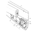
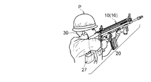
- the receiving unit 27 which is another element constituting the sound effect generating device 20 according to the present invention, is illustrated as an appearance in FIG. 6, a usage state in FIG. 7, and a block diagram in FIG.
- 28 is a power supply battery
- 29 is an on / off switch
- 30 is an antenna (the one shown is a dummy. However, it is a matter of course that a practical antenna may be used).
- Reference numeral 31 is a selection button for a reproduction sound (firing sound)
- 32 is a jack
- 33 is a knob for volume control operation
- 34 is a pilot lamp.
- the receiving unit 27 in FIG. 6 has a front design like an operation unit imitating a transceiver as a form, but has only a shape and no function.
- each operation unit functions.
- the gun body vibrates thereby, and the vibration is detected by the vibration detection sensor. 19, the transmission unit 16 is driven, and the detection signal is received by the reception unit 27 together with the ID.
- the receiving unit 27 is illustrated as a block diagram in FIG. As shown in the figure, the receiving unit 27 includes a receiving module 35, an arithmetic processing unit 36, an output sound memory 37, a rectification amplification circuit 38 for output rectification, output sound conversion and amplification, and the like. Further, sounding means 39 for reproducing the emitted sound is connected to the last stage. A headphone or a speaker can be used as the sound generation means 39. The headphone is used by being connected to the jack 32. Usable headphones include so-called earphones (illustrated in FIG. 7).
- the receiving module 35 of the receiving unit 27 includes a coupler unit 35a that checks a received signal from the antenna 30, an automatic signal processing device 35c that processes the received signal with the involvement of the operation signal generating unit 35b, and the processed reception signal.
- a demodulator 35d that demodulates the FM modulated signal of the signal, a data slicer 35e that compares and confirms the data content with a threshold value, a packet signal processing unit 35f of the received signal, a received signal processing unit interface (RxFiFO), and a signal in the module It consists of a register 35g for confirming a processing route (memory storage location) and a signal processing interface 35h to the next stage.
- the receiving module 35 has the same configuration as the transmitting module 26, and a part of the receiving module 35 is properly used for transmission and reception. Therefore, the cost can be halved compared with the dedicated circuit.
- the receiving unit 27 sets the ID in the setting mode and writes it in the memory (EEPROM in the CPU), reads the set ID in the normal mode, and receives the same ID as the set ID from the transmitting unit 16.
- the transmitter 16 is identified by the ID, and any sound data is selected from a plurality of sound data stored in the memory 37, and the selected sound data is recalled from the memory.
- a central processing unit 36 for outputting to the sounding means.
- the central processing unit 36 collates the received signal with the ID of the memory (EEPROM) 37 in the CPU, and when it matches, calls out the sound from the memory 37 and transmits it to the filters 38a and 38b in the next stage.
- the central processing unit 36 is composed of a CPU, and a clock synchronous CPU module is used for the CPU. In the central processing unit 36, processing mainly for exchanging information between the receiving module 35 and the output sound memory 37 is performed.
- the output sound memory 37 is indispensable, for example, to enable reproduction of the firing sound unique to the modeled simulated gun, and characterizes the data that characterizes the aforementioned M4A1 carbine firing sound or the firing sound of the AK47. Data, and further data that characterizes the sound that changes depending on the type of bullet are written.
- the output sound memory 37 is preferably a nonvolatile memory such as a flash EEPROM or a flash ROM. These many reproduced sounds (fired sounds) are selected in advance by operating the reproduced sound selection button 31 in the receiving unit 27.
- the rectifying and amplifying circuit 38 includes two-stage noise filters 38a and 38b, a volume adjusting unit 38c, and a reproducing volume amplifying unit 38d.
- As the noise filters 38a and 38b so-called low pass filters (LPF) are used.
- the last stage is the sound generation means 39. For this reason, as described above, the speaker can be used in addition to the headphones including the earphones.
- LPF low pass filters
- the on / off switch 18 of the transmitter 16 is turned on (ST1), the CPU operation port and clock are initialized (ST2), and the normal operation mode or the setting operation mode is selected from the operation mode (ST3).
- the mode of the setting operation is a mode that is necessary at the time of manufacture, repair, etc., which initializes the RS232C communication port and prepares for communication (ST8). Is ID written in a rewritable memory (EEPROM)?
- the mode for generating sound effects is the normal operation mode.
- the ID set in the EEPROM is read according to a predetermined program (ST4). A number from 0 to 999 is used for the ID, and a number unique to the simulated gun 10 of the user P is selected as the ID.
- the signal processing CPU module 25 and the transmission module (communication module in FIG. 5) 26 start operating (ST5), and whether vibration is detected by the vibration detection sensor 19 or not. Is confirmed (ST6), and if it is confirmed, the detection signal and the ID for identifying the firing sound unique to the gun body are transmitted from the transmission module 26 (ST7 in FIG. 9).
- a predetermined sequence is started (ST1). That is, the operation port and lock of the CPU module 36 are initialized, and the preparation for starting the operation is completed (ST2).
- a normal operation mode or a setting operation mode is selected according to the operation mode (ST3).
- the output sound memory 37 of the receiving unit 27 stores sound data of several kinds of fired sounds in advance. Each time the playback sound selection button 31 is pressed in ST6 of FIG. 10, the playback sound 1 ⁇ 2 ⁇ 3 ⁇ 1 ⁇ (ST7 in FIG. 10), and the reproduction sound selected here is reproduced when the set ID is received.
- the setting mode is a mode that is necessary at the time of manufacture, repair, etc., and initializes the RS232C communication port and prepares for communication (ST10), and writes ID into a rewritable memory (EEPROM). (ST11), the ID is written in the EEPROM (ST12), the ID written in ST12 is confirmed (ST13), the written ID is transmitted to the communication port, and the process ends (ST14).
- a program that generates sound effects operates.
- the ID set in the EEPROM is read (ST4). Numbers such as 0 to 999 are used for the ID, and an ID that matches the ID of the simulated gun 10 of the user P is selected from among the numbers.
- the signal processing CPU module 36 and the receiving module start operation (ST5), and it is confirmed whether or not the switch of the reproduction sound selection button 31 is pressed (ST6). Changes the emission sound data to be output to the selected emission sound (ST7), and further confirms whether a radio signal is received from the transmitter of the same ID number (ST8).
- the sound data selected in ST7 is called from the output sound data 37 and output to the sound generation means 39 (ST9).
- the ID is set in the transmission unit in the setting mode, the ID is written in the memory (EEPROM in the CPU) arranged in the transmission unit, and the set ID is read in the normal mode.
- the above ID written in the memory is transmitted.
- the receiving unit also sets the ID in the setting mode, writes to the memory, reads the set ID in the normal mode, and sets the transmitting unit and the receiving unit at the same time. Is also possible. With this configuration, it is possible to rewrite sound data and the like, and more freedom is expected.
Abstract
【課題】受信部の側に装備した発音手段にて発射音を発生させることによりクリヤーな発射音の再生を実現するとともに、そのクリヤーな発射音を、一つの受信機に対して一つの送信機を限定して再生する。 【解決手段】銃本体側に送信部を装備し、銃本体側から離れた位置に受信部を装備し、上記銃本体の発射操作により送信部を駆動し、受信部の側に装備した発音手段にて発射音を発生させる模擬銃における効果音発生装置として、発射操作を検出する発射検出装置19を銃本体の側に有し、かつ、発射検出装置による発射検出信号を、上記銃本体固有のIDとともに送信する送信部16と、上記送信部から送信された発射検出信号とIDを受信するとともに、IDによって送信部16を特定し、発射音を再生させる発音手段39を備えた受信部27とから構成する。
Description
本発明は送信部を装備した銃本体の側と、受信部を装備した銃本体の側から離れた位置の間にて、上記銃本体の発射操作に伴う通信を行い、受信部の側に装備した発音手段にて発射音を発生させる模擬銃における効果音発生装置に関するものである。
いわゆる電動ガンやエアソフトガン、或いはモデルガンに類するものは、単なる玩具の域を超えて社会に受け入れられている。例えば、出願人の製品は、一部が防衛省をはじめとする政府機関にも納入されており、同省の場合は近接戦闘の訓練用などとして使用されている。これらの銃は、実銃に対して模擬銃とも呼ばれるが、発射音が実銃と全く異なるという相違点がある。
発射音を発生させるようにした模擬銃も提案されている。しかし、その内のあるものは銃の内部に小型スピーカーを組み込む方式であったので迫力のある発射音を得られず、また、スピーカーを組み込む必要上、或る程度は大型の銃以外に適用できないという問題があった。これに対して、特開平6‐66497号の発明は、弾丸の発射に伴って、複数の射撃音の中から一つの射撃音を選択的に発生させる装置を開示している。同発明は銃の内部に発音装置やスピーカー等を組み込んではいないので、銃の外形を損なわず、小型のスピーカーを使用しなければならない等の制約はない。しかし、固定された制御ボックスにフレキシブルパイプによって遊戯銃を取り付けた形式であるので、銃を携行することが最初から考慮されておらず、実銃を模して作られることが多い模擬銃には適用することが困難である。
また、実用新案登録第3057385号は、銃玩具の内部に備えた銃弾発射音の音声チップ出力をFM電波で送信し、近くに置いた大型のスピーカーを駆動するという発想を備えている。送信された電波はFMステレオ受信機などで受信し、受信機に備えたグラフイックイコライザーなどでオーディオ再生周波数帯を補正できるようにし、銃弾発射音をよりリアルに再生可能とする。しかしながら、銃弾発射音の音声チップ出力をFM電波で送受信する方式のため、受信器が雑音を拾ってしまうことがあり、ノイズが混じることで生じる問題がある。特に、複数台の模擬銃を用いてサバイバルゲーム等を行う場合、受信機が自分以外の模擬銃の送信機からの信号を拾ってしまい、誰の射撃かを区別することが困難になるという点は問題である。また、ノイズや電波状況によって、音が途切れたり雑音が混入したりすること等は、電波によって音データを飛ばす場合に付いて回る問題であるので、慎重な全体設計が必要になる。
本発明は前記の実情に鑑みてなされたもので、その課題は、受信部の側に装備した発音手段にて発射音を発生させることによりクリヤーな発射音の再生を実現するとともに、そのクリヤーな発射音を、一つの受信機に対して一つの送信機を限定して再生することができるようにすることである。また、本発明の他の課題は、銃の発射を感知したという情報とIDのみから成る信号を送信することにより、ノイズや音の途切れのない、高音質の発射音を聞くことができるようにすることである。
前記の課題を解決するため、銃本体の側に送信部を装備し、銃本体の側から離れた位置に受信部を装備し、上記銃本体の発射操作により送信部を駆動し、受信部の発音手段にて発射音を発生させる模擬銃における効果音発生装置について、発射操作を検出する発射検出装置を銃本体の側に有し、かつ、発射検出装置による発射検出信号を、上記銃本体固有のIDとともに送信する送信部と、上記送信部から送信された発射検出信号とIDを受信するとともに、IDによって送信部を特定し、発射音を再生させる発音手段を備えた受信部とから構成するという手段を講じたものである。
本発明の模擬銃における効果音発生装置は、銃本体の側に送信部を装備し、銃本体の側から離れた位置に受信部を装備し、上記銃本体の発射操作により送信部を起動し、受信部の発音手段にて発射音を発生させる点において、先行する自社出願のものと共通である。しかし、ヘッドホンを使用して、サバイバルゲームや、シューティング競技において、臨場感溢れる発射音を聴取することができるのは勿論、一つの受信機に対して一つの送信機を限定できるようにしたことを特徴とする。
なお、本発明において、銃本体の側とは、狭義の銃本体つまり銃を構成する主として構造的な部分と、それ自体銃本体とまではいえないが銃本体と組み合わされて機能向上に寄与するものとを含む。例えば、ストック(銃床)やハンドガード(被筒)は前者に属し、消音器(サイレンサー)などは後者に属するといえる。弾倉(マガジン)はどちらともいえないが、銃に不可欠であることに相違はない。従って、本発明を構成する送信部は、前者にも後者にも装備し得る。
そして、本発明の上記特徴は、発射操作を検出する発射検出装置を銃本体の側に有し、かつ、発射検出装置による発射検出信号を、上記銃本体固有のIDとともに送信する送信部と、上記送信部から送信された発射検出信号とIDを受信するとともに、IDによって送信部を特定し、発射音を再生させる発音手段を備えた受信部とから成る構成によって達成される。なお、本発明はどの模擬銃が発射されたのかを特定するためにIDを使用するものであるから、同一の場で使用される模擬銃の個数とIDの個数とは一致するだけの個数が必要である。しかし、銃本体固有の発射音の種類の数とIDの個数とが一致する必要は必ずしもない。本発明の装置は、銃本体の側では発射検出装置による検出信号と当該銃本体固有のIDを送信するという点、換言すれば、発射音を送信しない点が重要であり、この構成によって、ノイズや音の途切れのない、高音質の発射音を再生することが可能になる。
発射検出装置としては、例えば、発射操作により銃本体に生じた振動を検出する振動検出センサーを銃本体の側に設けることができ、送信部は、振動検出センサーによる検出信号と、当該銃本体固有のIDを送信する。受信部は、上記送信部から送信された検出信号とIDを受信するとともに、IDによって特定される銃本体の発射音を再生させる発音手段を備えた構成とすることができる。振動検出は飽くまで一つの手段であり、他にもトリガーによるスイッチング法、弾丸通過を赤外光等により検出する法、発射音を検出する法など公知の検出手段、方法を採用することができる。
本発明の効果音発生装置として、送信部が、設定モードにて銃本体固有のIDを設定するとともに、送信部に配置されたメモリーに書き込みを行ない、通常モードにて設定済みIDの読み込みを行ない、設定モードにてメモリーに書き込まれた上記IDを送信するための中央処理装置を備えており、受信部は、設定モードにてIDを設定するとともにメモリーに書き込みを行ない、通常モードにて設定済みIDの読み込みを行い、設定済みIDと同じIDを送信部から受信したときにIDによって送信部を特定し、かつ、メモリーに記憶されている複数個の音データの中から任意の音データをあらかじめ選択しておくとともに、選択された音データをメモリーから呼び出し、発音手段に出力するための中央処理装置を備えている構成は望ましいものである。上記中央処理装置には中央演算処理装置とも称されるいわゆるCPUが用いられる。
また、銃本体の側に装備する送信部は、銃本体に設けられたハンドガード又はストックにおける発射機構の直前又は直後の位置に組み込まれることが望ましい。何故なら、ハンドガード又はストックも銃本体の側に属するとともに、発射操作により生じる振動の発生源に直接関係しており、かつ、その直前又は直後であれば振動検出により有効であるからである。また、ハンドガード又はストックは相当の大きさを有するので、それらの内部を本発明の効果音発生装置の組み込み場所に、無理なく使用できるからである。
本発明は以上のように構成され、かつ作用するものであるから、受信部の側に装備した発音手段にて発射音を発生させることによりクリヤーな発射音の再生を実現することができるとともに、一つの送信機と一つの受信機を対応させて再生することができ、従って、自分の使用している模擬銃の発射音を明確に聴取できるのは勿論、他人の発射音と明確に区別することができるという効果を奏する。特に、本発明によれば、銃の発射を感知したという情報とIDのみから成る信号を送受信することにより、発射音を送受信しないで済むから、受信部に用意されたノイズや音の途切れのない、高音質の発射音を聞くことができる。
以下、図示の実施形態を参照して本発明をより詳細に説明する。図1は本発明に係る効果音発生装置を適用した模擬銃10を示すもので、11はストック、12はハンドガードをそれぞれ示す。この模擬銃10は、トリガー13とその操作に伴って作動する、図示していない弾丸発射機構を有しており、マガジン14から供給されるBB弾と称する球形弾丸をバレル15の先端から発射することができる構成を備えているものとする。
模擬銃10は、銃本体の側に送信部16を装備する。送信部16は、銃本体側であればどの位置にも装備することができ、本実施形態では、例えば、ストック11とハンドガード12に送信部16を装備した二例を代表として、後述のとおり説明する。なお、図1はM4A1カービンをモデルとする模擬銃を示しており、これはストック11とハンドガード12の両方を有する点が好都合なので例示したものであるが、ストック11やハンドガード12の形態等まで同じという趣旨ではなく、それらが送信部16の取り付け部になり得るということが重要である(従って、図1における符号16-1、16-2は、送信部を設け得る位置のみを例示している(なお、ストックへの取付け例は、AK47のものについて図3に示している。)。
上記のような模擬銃10は、駆動方法により幾つかのタイプに分けることができる。中でも、モーターによりピストンを駆動し生成した圧縮エアにより弾丸を発射する電動ガンと、ガスボンベから供給される圧縮ガスにより弾丸を発射するガスガンが一般的であり、本発明は上記又は上記以外の模擬銃全般に適用することができる。いずれのタイプの模擬銃でも、トリガー13の操作の後、弾丸が発射されるまでの時間は瞬間的で、かつ、発射時又はその直前付近で最も大きな振動が発生すると考えて良いので、上記振動を検出することを想定して振動検出センサー19又は本発明の効果音発生装置20を配置する向きや位置等を選定する。従って、本実施形態における振動検出センサー19は、本発明における発射検出装置である。
上記効果音発生装置20を構成する送信部16は、電源電池17、オン・オフスイッチ18、振動検出センサー19、送信基板21、感度調節用ボリューム22及び操作用摘み22a等を主要な構成部品として構成されている。17aは電池蓋、17bは電池収容部、18aはスイッチ操作片、23はケースを示している。ケース23は23a、23bは左右二部分から成り、本装置20の構成要素を組み込み、一つのユニット又はアセンブリとして扱えるように構成されている。図2はその一例である、しかし、本装置20の送信部16をケース23に組み込むことが絶対的に必要な条件というわけではない。
図3は本発明に係る実施形態の例1を示しており、これは本装置20の送信部16をストック11に実装した例である。図3には上記図2におけるのと同じ符号を使用して、各部の構成部品の詳細な説明に替えているが、同図から理解されるように、ストック11は送信部16を収めるのに必要十分な大きさを有している。また、ストック11は発射機構の直後に位置しており、発射操作により銃本体に生じた振動を人体の肩に伝える部分でもあるので、上記振動を検出するためにも好都合である。
また、図4は、本装置20の送信部16をハンドガード12に実装した、実施形態の例2を示している。各部の構成部品について、上記図2におけるのと同じ符号を使用しているのは図3と同様である。図4から理解されるように、ハンドガード12は送信部16を収めるのに必要十分な大きさを有している。また、ハンドガード12は発射機構の直前に位置してバレル15の周囲を囲んでおり、発射操作により銃本体に生じた振動が直接に伝わる部分であるので、上記振動を検出するために都合が好い。
本発明の上記効果音発生装置20(図7参照)を構成する送信部16は、図5にブロック図として例示されている。既に言及した電源電池17、オン・オフスイッチ18、振動検出センサー19等の同じ符号は各図において、同じ要素を示している。また、上記送信部16は、振動検出センサー19、振動信号波整流及び増幅のための整流増幅回路24、中央演算処理装置25及び送信モジュール26から構成されている。
上記送信部16に使用する振動検出センサー19として、実施形態では、発射操作により銃本体の側に生ずる振動を信号電圧に変換する圧電素子を使用する。上記振動検出センサー19は、その感度と弾丸発射時の振動とを適合させるために、弾丸の発射方向とほぼ直角に配置されている。振動が発射操作によるものか又は単に銃に加わった衝撃によるものを判断して、誤動作を防止するために、振動数の相違に着目して区別することも有効である。本実施形態の場合、圧電素子にて変換された信号電圧を増幅するセンサーアンプを具備して、上記センサーアンプが5.5~6.5KHzの振動を重点的に増幅する周波数フィルターを兼ねるように構成されている。上記数値範囲は模擬銃10に触れた時と、発射時との相違を、最も見分けやすい周波数である。
上記電源電池17には、電源電圧の安定化のために、安定化回路17cが設けられている(図5参照)。また、前記整流増幅回路24は、振動検出センサー19からの検出信号をフィルタリングするとともに、整流する2段のフィルター24a、24bと、各段にて整流された信号を増幅する2段の増幅部24c、24dとから構成されており、上記フィルターにはバンドパスフィルター(BPF)を使用している。上記送信部16は、振動検出センサー19にて検出した信号電流を、IDとともに送信することを特徴とする。そのために、送信部16は、設定モードにて当該銃本体に固有のIDを設定するとともに、送信部に配置されたメモリー(CPU内のEEPROM)への書き込みを行ない、通常モードにて設定済みIDの読み込みを行ない、設定モードにてメモリーに書き込まれた上記IDを送信するための中央演算処理装置25を備えている。中央演算処理装置25には、クロック同期型のCPUが使用される。
上記送信部16の送信モジュール26は、中央演算処理装置25からのデジタル信号を送信のために処理する機能を備えており、上記振動検出センサー19による検出信号は、図9のステップ10(ST10)における送信プログラム書込み時点で設定されるIDと共に信号処理インターフェイス26aに入力される。入力された信号の処理のために、モジュール内での信号処理ルート(メモリー格納場所)を確認するレジスター26b、送信信号処理部インターフェイス(TxFiFO)とともに、パケット信号処理部26cが設けられている。検出信号は信号波形チェック部26dにて波形のチェックとシェイピングがなされ、その後FM変調のために変調器26eに入力される。IDには、例えば、0~999の数字を当てることができる。
FM変調された検出信号は、動作用信号発生部26fの関与を受ける自動信号処理装置26gに送られ、また、送信アンテナ用信号チェックのためにカップラー部26hを経てアンテナ26iより送信される。ここでFM変調された信号を使用するが、信号に発射音情報が含まれている訳ではないので、受信の際に雑音を拾ったとしても発射音にノイズ等が混入することがない。26kは電源管理部であり、送信モジュール26の電源電流及び電圧の管理のために設けられている。なお、本実施形態の送受信モジュールには2.4GHzのモジュールを用いており、この周波数は汎用部材を使用する目的で選択されたが、応答速度が速いという利点がある。
本発明に係る上記効果音発生装置20を構成するもう一つの要素である受信部27は、図6に外観、図7に使用状態、図8にブロック図として例示されている。各図中、28は電源電池、29はオン・オフスイッチ、30はアンテナ(図示のものはダミーである。しかし、実用のアンテナであっても良いのは勿論である。)。31は再生音(発射音)の選択ボタン、32はジャック、33は音量調節用ボリュームの操作用摘み、34はパイロットランプをそれぞれ示す。図6の受信部27は形態としてトランシーバーを模した操作部のような正面のデザインを有しているが形だけで機能は持っていない。しかし、各操作部が機能するデザインを取ることも、当然可能である。このように構成されている本発明の効果音発生装置では、模擬銃10の使用者Pがトリガー13を引き発射操作がなされると、それにより銃本体に振動を生じ、その振動が振動検出センサー19に検出され、送信部16が駆動され、検出信号はIDと共に受信部27に受信されるものである。
受信部27は、図8にブロック図として例示されている。受信部27は、同図に示されているように受信モジュール35、演算処理装置36、出力音メモリー37、出力整流、出力音変換及び増幅のための整流増幅回路38などから構成されている。また、発射音を再生させる発音手段39が最終段に接続される。発音手段39としてはヘッドホンないしスピーカーを使用可能であり、ヘッドホンは前記のジャック32に接続して使用され、使用可能なヘッドホンにはいわゆるイヤホン(図7に例示されている。)も含まれる。
上記受信部27の受信モジュール35は、アンテナ30からの受信信号をチェックするカップラー部35a、受信信号を動作用信号発生部35bの関与を受けて処理する自動信号処理装置35c、処理された上記受信信号のFM変調信号を復調する復調器35d、データ内容を閾値と比較、確認するデータスライサー35e、受信信号のパケット信号処理部35f、受信信号処理部インターフェイス(RxFiFO)を経て、モジュール内での信号処理ルート(メモリー格納場所)を確認するレジスター35g、次段への信号処理インターフェイス35h、から構成されている。図8を図5と見比べることから分かることであるが、受信モジュール35は送信モジュール26と同じ構成を有しており、その一部を送信時と受信時で使い分けている。故に、専用回路と比較してコストを半減することが可能になる。
受信部27は、設定モードにてIDを設定するとともにメモリー(CPU内のEEPROM)に書き込みを行ない、通常モードにて設定済みIDの読み込みを行い、設定済みIDと同じIDを送信部16から受信したときにIDによって送信部16を特定し、かつ、メモリー37に記憶されている複数個の音データの中から任意の音データをあらかじめ選択しておくともに、選択された音データをメモリーから呼び出し、発音手段に出力するための中央演算処理装置36を備えている。上記中央演算処理装置36は、受信信号をCPU内のメモリー(EEPROM)37のIDと照合し、合致したときに上記メモリー37から発射音を呼び出し、次段のフィルター38a、38bに送信する。中央演算処理装置36は、CPUから構成されており、そのCPUには、クロック同期型のCPUモジュールが使用される。上記中央演算処理装置36では、受信モジュール35及び出力音メモリー37等との間にて情報のやり取りを主とする処理が行なわれる。
上記出力音メモリー37は、例えば、モデルとした模擬銃に固有の発射音の再生を可能にするために不可欠のもので、前述したM4A1カービンの発射音を特徴付けるデータ、或いはAK47の発射音を特徴付けるデータ、さらには、弾丸の種類によって変わる発射音を特徴付けるデータなどが書き込まれる。出力音メモリー37にはフラッシュEEPROM、フラッシュROMなどという不揮発性メモリーが好適である。それら多数の再生音(発射音)は、受信部27における再生音選択ボタン31の操作によって、あらかじめ選択される。
また、整流増幅回路38は、2段のノイズフィルター38a、38b、音量調整部38c、再生音量の増幅部38dから構成されている。ノイズフィルター38a、38bとしては、いわゆるローパスフィルター(LPF)を使用している。最終段は発音手段39であり、このために、イヤホンを含むヘッドホンのほかスピーカーを使用することができるのは前記したとおりである。
このような構成を有する本発明の模擬銃における効果音発生装置20の作用について、その作動を示すフローチャートと共に説明する(図9参照)。初めに送信部16のオン・オフスイッチ18をオンとして(ST1)、CPUの動作用ポートとクロックを初期化し(ST2)、動作モードから通常動作又は設定動作のモードを選択する(ST3)。設定動作のモードは製造時、修理時等に必要になるモードで、RS232C通信用ポートを初期化し通信の準備を行なうもので(ST8)、書き換え可能なメモリー(EEPROM)にIDの書き込みを行なうかどうかを問い合わせ(ST9)、EEPROMに送信用プログラムを書込む際、同時に0~999までの数字を用いるIDの書き込みを行ない(ST10)、書き込んだIDを確認の上(ST11)、書き込んだIDを通信ポートに送信して終了する(ST12)。これらの動作は所定のプログラムの下で進行する。
効果音を発生させるモードは通常動作モードで行なわれる。通常動作モードが選択されると所定のプログラムに従って、EEPROMに設定されているIDの読み込みが行なわれる(ST4)。IDには0~999の数字等が使用されており、その中から使用者Pの模擬銃10に固有の数字をIDとして選択する。次いで、銃本体の発射操作がなされることによって、信号処理CPUモジュール25と送信モジュール(図5の通信モジュール)26が動作を開始し(ST5)、振動検出センサー19にて振動が検出されたかどうかを確認し(ST6)、確認した場合には検出信号と当該銃本体固有の発射音を特定するIDが送信モジュール26より送信される(図9のST7)。
受信部27においても、初めにオン・オフスイッチ29をオンとすると、所定のシークエンスが開始される(ST1)。即ち、CPUモジュール36の動作用ポート及びロックの初期化が行なわれ、動作開始の準備が完了する(ST2)。動作モードにより、通常動作又は設定動作のモードを選択する(ST3)。設定モードでは、受信部27の出力音メモリー37にはあらかじめ数種類の発射音の音データが記憶されており、図10のST6において再生音選択ボタン31が押されるたびに、再生音1→2→3→1~の如く変更し(図10のST7)、ここで選択された再生音が設定済みIDを受信したときに再生されることになる。設定モードは、製造時、修理時等に必要になるモードであり、RS232C通信用ポートを初期化し、通信の準備を行うために(ST10)、書き換え可能なメモリー(EEPROM)にIDの書き込みを行うかどうかを問い合わせ(ST11)、EEPROMにIDの書き込みを行い(ST12)、ST12で書き込んだIDを確認の上(ST13)、書き込んだIDを通信ポートに送信して終了する(ST14)。
通常動作モードでは効果音を発生させるプログラムが作動する。通常動作モードが選択されるとEEPROMに設定されているIDの読み込みが行なわれる(ST4)。IDには、0~999の数字等が使用されており、その中から使用者Pの模擬銃10のIDに適合したIDが選択される。次いで信号処理CPUモジュール36と受信モジュール(図9の通信モジュール)35が動作を開始し(ST5)、再生音選択ボタン31のスイッチが押されたかどうかを確認し(ST6)、押された場合には出力する発射音データを選択されている発射音に変更し(ST7)、さらに、同一ID番号の送信機から無線信号を受信したかどうかが確認される(ST8)。同一ID番号の送信機から無線信号を受信したときは、ST7で選択された音データが出力音データ37から呼び出され、発音手段39に出力する(ST9)。
本発明においては、送信部に設定モードにてIDを設定するとともに、送信部に配置されたメモリー(CPU内のEEPROM)に書き込みを行ない、通常モードにて設定済みIDの読み込みを行ない、設定モードにてメモリーに書き込まれた上記IDを送信する。これに対して、受信部においても、設定モードにてIDを設定するとともに、メモリーへの書き込みを行ない、通常モードにて設定済みIDの読み込みを行ない、送信部と受信部における設定を同時に行なうことも可能である。この構成により、音データの書き換え等も可能になり、また、より自由が増すと考えられる。
10 模擬銃
11 ストック
12 ハンドガード
13 トリガー
14 マガジン
15 バレル
16 送信部
17、28 電源電池
18、29 オン・オフスイッチ
19 振動検出センサー
20 効果音発生装置
21 基板
22 感度調節用ボリューム
23 ケース
24、38 整流増幅回路
25、36 演算処理装置
26 送信モジュール
27 受信部
30 アンテナ
31 再生音選択ボタン
32 ジャック
33 音量調節用ボリュームの操作用摘み
34 パイロットランプ
35 受信モジュール
37 出力音メモリー
39 発音手段
11 ストック
12 ハンドガード
13 トリガー
14 マガジン
15 バレル
16 送信部
17、28 電源電池
18、29 オン・オフスイッチ
19 振動検出センサー
20 効果音発生装置
21 基板
22 感度調節用ボリューム
23 ケース
24、38 整流増幅回路
25、36 演算処理装置
26 送信モジュール
27 受信部
30 アンテナ
31 再生音選択ボタン
32 ジャック
33 音量調節用ボリュームの操作用摘み
34 パイロットランプ
35 受信モジュール
37 出力音メモリー
39 発音手段
Claims (3)
- 銃本体の側に送信部を装備し、銃本体の側から離れた位置に受信部を装備し、上記銃本体の発射操作により送信部を駆動し、受信部の側に装備した発音手段にて発射音を発生させる模擬銃における効果音発生装置であって、
発射操作を検出する発射検出装置を銃本体の側に有し、かつ、発射検出装置による発射検出信号を、上記銃本体固有のIDとともに送信する送信部と、
上記送信部から送信された発射検出信号とIDを受信するとともに、IDによって送信部を特定し、発射音を再生させる発音手段を備えた受信部とから構成される
ことを特徴とする模擬銃における効果音発生装置。 - 送信部は、設定モードにて銃本体固有のIDを設定するとともに、送信部に配置されたメモリーに書き込みを行ない、通常モードにて設定済みIDの読み込みを行ない、設定モードにてメモリーに書き込まれた上記IDを送信するための中央処理装置を備えており、
受信部は、設定モードにてIDを設定するとともにメモリーに書き込みを行ない、通常モードにて設定済みIDの読み込みを行い、設定済みIDと同じIDを送信部から受信したときにIDによって送信部を特定し、かつ、メモリーに記憶されている複数個の音データの中から任意の音データをあらかじめ選択しておくともに、選択された音データをメモリーから呼び出し、発音手段に出力するための中央処理装置を備えている
請求項1記載の模擬銃における効果音発生装置。 - 銃本体の側に装備する送信部は、銃本体に設けられたハンドガード又はストックにおける発射機構の直前又は直後の位置に組み込まれている
請求項1又は2記載の模擬銃における効果音発生装置。
Priority Applications (2)
| Application Number | Priority Date | Filing Date | Title |
|---|---|---|---|
| PCT/JP2013/062725 WO2014178136A1 (ja) | 2013-05-01 | 2013-05-01 | 模擬銃における効果音発生装置 |
| TW102125845A TW201443384A (zh) | 2013-05-01 | 2013-07-19 | 模擬槍之音效發生裝置 |
Applications Claiming Priority (1)
| Application Number | Priority Date | Filing Date | Title |
|---|---|---|---|
| PCT/JP2013/062725 WO2014178136A1 (ja) | 2013-05-01 | 2013-05-01 | 模擬銃における効果音発生装置 |
Publications (1)
| Publication Number | Publication Date |
|---|---|
| WO2014178136A1 true WO2014178136A1 (ja) | 2014-11-06 |
Family
ID=51843287
Family Applications (1)
| Application Number | Title | Priority Date | Filing Date |
|---|---|---|---|
| PCT/JP2013/062725 WO2014178136A1 (ja) | 2013-05-01 | 2013-05-01 | 模擬銃における効果音発生装置 |
Country Status (2)
| Country | Link |
|---|---|
| TW (1) | TW201443384A (ja) |
| WO (1) | WO2014178136A1 (ja) |
Cited By (1)
| Publication number | Priority date | Publication date | Assignee | Title |
|---|---|---|---|---|
| WO2020183041A1 (es) * | 2019-03-14 | 2020-09-17 | Caballero Janina Manuel | Dispositivo electrónico simulador del sonido de armas de fuego |
Citations (4)
| Publication number | Priority date | Publication date | Assignee | Title |
|---|---|---|---|---|
| JPS5020600A (ja) * | 1973-06-28 | 1975-03-04 | ||
| JP2008175454A (ja) * | 2007-01-18 | 2008-07-31 | Hitachi Kokusai Electric Inc | 訓練用端末装置 |
| JP2009019807A (ja) * | 2007-07-11 | 2009-01-29 | Hitachi Kokusai Electric Inc | 射撃訓練システム |
| JP2012215373A (ja) * | 2011-03-29 | 2012-11-08 | Hitachi Kokusai Electric Inc | 射撃訓練装置 |
-
2013
- 2013-05-01 WO PCT/JP2013/062725 patent/WO2014178136A1/ja active Application Filing
- 2013-07-19 TW TW102125845A patent/TW201443384A/zh unknown
Patent Citations (4)
| Publication number | Priority date | Publication date | Assignee | Title |
|---|---|---|---|---|
| JPS5020600A (ja) * | 1973-06-28 | 1975-03-04 | ||
| JP2008175454A (ja) * | 2007-01-18 | 2008-07-31 | Hitachi Kokusai Electric Inc | 訓練用端末装置 |
| JP2009019807A (ja) * | 2007-07-11 | 2009-01-29 | Hitachi Kokusai Electric Inc | 射撃訓練システム |
| JP2012215373A (ja) * | 2011-03-29 | 2012-11-08 | Hitachi Kokusai Electric Inc | 射撃訓練装置 |
Cited By (1)
| Publication number | Priority date | Publication date | Assignee | Title |
|---|---|---|---|---|
| WO2020183041A1 (es) * | 2019-03-14 | 2020-09-17 | Caballero Janina Manuel | Dispositivo electrónico simulador del sonido de armas de fuego |
Also Published As
| Publication number | Publication date |
|---|---|
| TW201443384A (zh) | 2014-11-16 |
Similar Documents
| Publication | Publication Date | Title |
|---|---|---|
| JP5611933B2 (ja) | 模擬銃における効果音発生装置 | |
| WO2014184875A1 (ja) | 模擬銃における銃操作の識別装置 | |
| CN202173772U (zh) | 一种有单兵远程音效的模拟野战激光对抗系统 | |
| US20130331002A1 (en) | IR Dongle with Speaker for Electronic Device | |
| US20160324140A1 (en) | Game animal distraction apparatus | |
| CN103115530B (zh) | 无线遥控的弹射式电子礼花爆竹 | |
| CN201799120U (zh) | 激光格斗装置 | |
| US9901825B2 (en) | System, apparatus, and method of monitoring interactions | |
| CN105214302B (zh) | 一种飞碟打靶系统、飞碟及电子枪 | |
| WO2014178136A1 (ja) | 模擬銃における効果音発生装置 | |
| US6198404B1 (en) | Small weapon decoy for military use | |
| WO2014178119A1 (ja) | 模擬銃における効果音発生装置 | |
| ES1300168U (es) | Equipo de entrenamiento y/o actividades lúdicas con armas de fuego y de operaciones de combate simuladas | |
| JP2021023517A (ja) | 演出制御システム、方法、プログラム | |
| US20120213397A1 (en) | Portable Speaker Apparatus | |
| JP4226915B2 (ja) | 遠隔操作玩具、及びその拡張ユニット | |
| WO2015029189A1 (ja) | 模擬銃における銃操作の識別装置 | |
| US20140329433A1 (en) | Toy Stuffed Animal with Remote Video and Audio Capability | |
| CN202020902U (zh) | 多人多编队仿真激光野战对抗系统 | |
| US9910636B1 (en) | Voice activated audio controller | |
| JP6522401B2 (ja) | 発光制御システム | |
| US20190054384A1 (en) | Toy Gun | |
| CN201226520Y (zh) | 部队野战数字音响 | |
| CN217961251U (zh) | 一种声光电智能打靶机 | |
| CN219802626U (zh) | 现场即时收音情境效果产生系统 |
Legal Events
| Date | Code | Title | Description |
|---|---|---|---|
| 121 | Ep: the epo has been informed by wipo that ep was designated in this application |
Ref document number: 13883800 Country of ref document: EP Kind code of ref document: A1 |
|
| NENP | Non-entry into the national phase |
Ref country code: DE |
|
| 122 | Ep: pct application non-entry in european phase |
Ref document number: 13883800 Country of ref document: EP Kind code of ref document: A1 |
|
| NENP | Non-entry into the national phase |
Ref country code: JP |