WO2014175606A1 - Appareil de transmission de signaux de diffusion, appareil destiné à recevoir des signaux de diffusion, procédé destiné à transmettre des signaux de diffusion et procédé destiné à revoir des signaux de diffusion - Google Patents
Appareil de transmission de signaux de diffusion, appareil destiné à recevoir des signaux de diffusion, procédé destiné à transmettre des signaux de diffusion et procédé destiné à revoir des signaux de diffusion Download PDFInfo
- Publication number
- WO2014175606A1 WO2014175606A1 PCT/KR2014/003403 KR2014003403W WO2014175606A1 WO 2014175606 A1 WO2014175606 A1 WO 2014175606A1 KR 2014003403 W KR2014003403 W KR 2014003403W WO 2014175606 A1 WO2014175606 A1 WO 2014175606A1
- Authority
- WO
- WIPO (PCT)
- Prior art keywords
- data
- mimo
- qam
- frame
- bit
- Prior art date
Links
Images


Classifications
-
- H—ELECTRICITY
- H04—ELECTRIC COMMUNICATION TECHNIQUE
- H04H—BROADCAST COMMUNICATION
- H04H20/00—Arrangements for broadcast or for distribution combined with broadcast
- H04H20/44—Arrangements characterised by circuits or components specially adapted for broadcast
-
- H—ELECTRICITY
- H04—ELECTRIC COMMUNICATION TECHNIQUE
- H04B—TRANSMISSION
- H04B7/00—Radio transmission systems, i.e. using radiation field
- H04B7/02—Diversity systems; Multi-antenna system, i.e. transmission or reception using multiple antennas
- H04B7/04—Diversity systems; Multi-antenna system, i.e. transmission or reception using multiple antennas using two or more spaced independent antennas
- H04B7/0413—MIMO systems
- H04B7/0456—Selection of precoding matrices or codebooks, e.g. using matrices antenna weighting
-
- H—ELECTRICITY
- H04—ELECTRIC COMMUNICATION TECHNIQUE
- H04L—TRANSMISSION OF DIGITAL INFORMATION, e.g. TELEGRAPHIC COMMUNICATION
- H04L1/00—Arrangements for detecting or preventing errors in the information received
- H04L1/004—Arrangements for detecting or preventing errors in the information received by using forward error control
- H04L1/0041—Arrangements at the transmitter end
-
- H—ELECTRICITY
- H04—ELECTRIC COMMUNICATION TECHNIQUE
- H04L—TRANSMISSION OF DIGITAL INFORMATION, e.g. TELEGRAPHIC COMMUNICATION
- H04L1/00—Arrangements for detecting or preventing errors in the information received
- H04L1/004—Arrangements for detecting or preventing errors in the information received by using forward error control
- H04L1/0045—Arrangements at the receiver end
-
- H—ELECTRICITY
- H04—ELECTRIC COMMUNICATION TECHNIQUE
- H04L—TRANSMISSION OF DIGITAL INFORMATION, e.g. TELEGRAPHIC COMMUNICATION
- H04L1/00—Arrangements for detecting or preventing errors in the information received
- H04L1/004—Arrangements for detecting or preventing errors in the information received by using forward error control
- H04L1/0056—Systems characterized by the type of code used
- H04L1/0057—Block codes
-
- H—ELECTRICITY
- H04—ELECTRIC COMMUNICATION TECHNIQUE
- H04L—TRANSMISSION OF DIGITAL INFORMATION, e.g. TELEGRAPHIC COMMUNICATION
- H04L1/00—Arrangements for detecting or preventing errors in the information received
- H04L1/004—Arrangements for detecting or preventing errors in the information received by using forward error control
- H04L1/0056—Systems characterized by the type of code used
- H04L1/0064—Concatenated codes
- H04L1/0065—Serial concatenated codes
-
- H—ELECTRICITY
- H04—ELECTRIC COMMUNICATION TECHNIQUE
- H04L—TRANSMISSION OF DIGITAL INFORMATION, e.g. TELEGRAPHIC COMMUNICATION
- H04L1/00—Arrangements for detecting or preventing errors in the information received
- H04L1/004—Arrangements for detecting or preventing errors in the information received by using forward error control
- H04L1/0056—Systems characterized by the type of code used
- H04L1/0071—Use of interleaving
-
- H—ELECTRICITY
- H04—ELECTRIC COMMUNICATION TECHNIQUE
- H04L—TRANSMISSION OF DIGITAL INFORMATION, e.g. TELEGRAPHIC COMMUNICATION
- H04L1/00—Arrangements for detecting or preventing errors in the information received
- H04L1/02—Arrangements for detecting or preventing errors in the information received by diversity reception
- H04L1/06—Arrangements for detecting or preventing errors in the information received by diversity reception using space diversity
-
- H—ELECTRICITY
- H04—ELECTRIC COMMUNICATION TECHNIQUE
- H04L—TRANSMISSION OF DIGITAL INFORMATION, e.g. TELEGRAPHIC COMMUNICATION
- H04L27/00—Modulated-carrier systems
- H04L27/18—Phase-modulated carrier systems, i.e. using phase-shift keying
- H04L27/20—Modulator circuits; Transmitter circuits
- H04L27/2032—Modulator circuits; Transmitter circuits for discrete phase modulation, e.g. in which the phase of the carrier is modulated in a nominally instantaneous manner
- H04L27/2035—Modulator circuits; Transmitter circuits for discrete phase modulation, e.g. in which the phase of the carrier is modulated in a nominally instantaneous manner using a single or unspecified number of carriers
- H04L27/2042—Modulator circuits; Transmitter circuits for discrete phase modulation, e.g. in which the phase of the carrier is modulated in a nominally instantaneous manner using a single or unspecified number of carriers with more than two phase states
- H04L27/2046—Modulator circuits; Transmitter circuits for discrete phase modulation, e.g. in which the phase of the carrier is modulated in a nominally instantaneous manner using a single or unspecified number of carriers with more than two phase states in which the data are represented by carrier phase
-
- H—ELECTRICITY
- H04—ELECTRIC COMMUNICATION TECHNIQUE
- H04L—TRANSMISSION OF DIGITAL INFORMATION, e.g. TELEGRAPHIC COMMUNICATION
- H04L27/00—Modulated-carrier systems
- H04L27/26—Systems using multi-frequency codes
- H04L27/2601—Multicarrier modulation systems
- H04L27/2697—Multicarrier modulation systems in combination with other modulation techniques
-
- H—ELECTRICITY
- H04—ELECTRIC COMMUNICATION TECHNIQUE
- H04L—TRANSMISSION OF DIGITAL INFORMATION, e.g. TELEGRAPHIC COMMUNICATION
- H04L27/00—Modulated-carrier systems
- H04L27/32—Carrier systems characterised by combinations of two or more of the types covered by groups H04L27/02, H04L27/10, H04L27/18 or H04L27/26
- H04L27/34—Amplitude- and phase-modulated carrier systems, e.g. quadrature-amplitude modulated carrier systems
- H04L27/3405—Modifications of the signal space to increase the efficiency of transmission, e.g. reduction of the bit error rate, bandwidth, or average power
-
- H—ELECTRICITY
- H04—ELECTRIC COMMUNICATION TECHNIQUE
- H04L—TRANSMISSION OF DIGITAL INFORMATION, e.g. TELEGRAPHIC COMMUNICATION
- H04L5/00—Arrangements affording multiple use of the transmission path
- H04L5/0001—Arrangements for dividing the transmission path
- H04L5/0003—Two-dimensional division
- H04L5/0005—Time-frequency
- H04L5/0007—Time-frequency the frequencies being orthogonal, e.g. OFDM(A), DMT
-
- H—ELECTRICITY
- H04—ELECTRIC COMMUNICATION TECHNIQUE
- H04B—TRANSMISSION
- H04B7/00—Radio transmission systems, i.e. using radiation field
- H04B7/02—Diversity systems; Multi-antenna system, i.e. transmission or reception using multiple antennas
- H04B7/10—Polarisation diversity; Directional diversity
-
- H—ELECTRICITY
- H04—ELECTRIC COMMUNICATION TECHNIQUE
- H04L—TRANSMISSION OF DIGITAL INFORMATION, e.g. TELEGRAPHIC COMMUNICATION
- H04L5/00—Arrangements affording multiple use of the transmission path
- H04L5/0001—Arrangements for dividing the transmission path
- H04L5/0014—Three-dimensional division
- H04L5/0023—Time-frequency-space
Definitions
- the present invention relates to an apparatus for transmitting broadcast signals, an apparatus for receiving broadcast signals and methods for transmitting and receiving broadcast signals.
- a digital broadcast signal may include a larger amount of video/audio data than an analog broadcast signal and further include various types of additional data in addition to the video/audio data.
- a digital broadcast system can provide HD (high definition) images, multi-channel audio and various additional services.
- HD high definition
- data transmission efficiency for transmission of large amounts of data, robustness of transmission/reception networks and network flexibility in consideration of mobile reception equipment need to be improved for digital broadcast.
- An object of the present invention is to provide an apparatus and method for transmitting broadcast signals to multiplex data of a broadcast transmission/reception system providing two or more different broadcast services in a time domain and transmit the multiplexed data through the same RF signal bandwidth and an apparatus and method for receiving broadcast signals corresponding thereto.
- Another object of the present invention is to provide an apparatus for transmitting broadcast signals, an apparatus for receiving broadcast signals and methods for transmitting and receiving broadcast signals to classify data corresponding to services by components, transmit data corresponding to each component as a data pipe, receive and process the data
- Still another object of the present invention is to provide an apparatus for transmitting broadcast signals, an apparatus for receiving broadcast signals and methods for transmitting and receiving broadcast signals to signal signaling information necessary to provide broadcast signals.
- the present invention provides a method of transmitting broadcast signals.
- the method of transmitting broadcast signals includes formatting input streams into Data Pipe, DP, data; Low-Density Parity-Check, LDPC, encoding the DP data according to a code rate; bit interleaving the LDPC encoded DP data; mapping the bit interleaved DP data onto constellations according to one of QAM(Quadrature Amplitude Modulation), NUQ(Non-Uniform QAM) or NUC(Non-Uniform Constellation); Multi-Input Multi-Output, MIMO, encoding the mapped DP data by using a MIMO encoding matrix having a MIMO encoding parameter; building at least one signal frame by mapping the MIMO encoded DP data; and modulating data in the built signal frame by an Orthogonal Frequency Division Multiplexing, OFDM, method and transmitting the broadcast signals having the modul
- the MIMO encoding is performed according to either FR-SM(Full-rate spatial multiplexing) method or FRFD-SM(Full-rate Full-diversity spatial multiplexing) method.
- the QAM, the NUQ and the NUC are defined depending on the code rate.
- the MIMO encoding parameter is defined based on one of the QAM, the NUQ or the NUC.
- the present invention provides a method of receiving broadcast signals.
- the method of receiving broadcast signals includes receiving the broadcast signals having at least one signal frame and demodulating data in the at least one signal frame by an Orthogonal Frequency Division Multiplexing, OFDM, method; parsing the at least one signal frame by de-mapping Data Pipe, DP, data; Multi-Input Multi-Output, MIMO, decoding the DP data by using a MIMO decoding matrix having a MIMO decoding parameter; de-mapping the MIMO decoded DP data from constellations according to one of QAM(Quadrature Amplitude Modulation), NUQ(Non-Uniform QAM) or NUC(Non-Uniform Constellation); bit de-interleaving the de-mapped DP data; Low-Density Parity-Check, LDPC, decoding the bit de-interleaved DP data according to a code rate; and de-formatting the LDPC decoded DP data into ouput streams.
- the MIMO decoding is performed according to either FR-SM(Full-rate spatial multiplexing) method or FRFD-SM(Full-rate Full-diversity spatial multiplexing) method.
- the QAM, the NUQ and the NUC are defined depending on the code rate.
- the MIMO decoding parameter is defined based on one of the QAM, the NUQ or the NUC.
- the present invention provides an appratus for transmitting broadcast signals.
- the appratus for transmitting broadcast signals includes a formatting module configured to format input streams into Data Pipe, DP, data; a Low-Density Parity-Check, LDPC, encoding module configured to LDPC encode the DP data according to a code rate; a bit interleaving module configured to bit interleave the LDPC encoded DP data; a mapping module configured to map the bit interleaved DP data onto constellations according to one of QAM(Quadrature Amplitude Modulation), NUQ(Non-Uniform QAM) or NUC(Non-Uniform Constellation); a Multi-Input Multi-Output, MIMO, encoding module configured to MIMO encode the mapped DP data by using a MIMO encoding matrix having a MIMO encoding parameter; a frame building module configured to build at least one signal frame by mapping the MIMO encoded DP data; a modulating module configured to modulate data
- the MIMO encoding module performs MIMO encoding according to either FR-SM(Full-rate spatial multiplexing) method or FRFD-SM(Full-rate Full-diversity spatial multiplexing) method.
- the QAM, the NUQ and the NUC are defined depending on the code rate.
- the MIMO encoding parameter is defined based on one of the QAM, the NUQ or the NUC.
- the present invention provides an appratus for receiving broadcast signals.
- the apparatus for receiving broadcast signals includes a receiving module configured to receive the broadcast signals having at least one signal frame; a demodulating module configured to demodulate data in the at least one signal frame by an Orthogonal Frequency Division Multiplexing, OFDM, method; a parsing module configured to parse the at least one signal frame by de-mapping Data Pipe, DP, data; a Multi-Input Multi-Output, MIMO, decoding module configured to MIMO decode the DP data by using a MIMO decoding matrix having a MIMO decoding parameter; a de-mapping module configured to de-map the MIMO decoded DP data from constellations according to one of QAM(Quadrature Amplitude Modulation), NUQ(Non-Uniform QAM) or NUC(Non-Uniform Constellation); a bit de-interleaving module configured to bit de-interleave the de-mapped DP data; a Low-Den
- the MIMO decoding module performs MIMO decoding according to either FR-SM(Full-rate spatial multiplexing) method or FRFD-SM(Full-rate Full-diversity spatial multiplexing) method.
- the QAM, the NUQ and the NUC are defined depending on the code rate.
- the MIMO decoding parameter is defined based on one of the QAM, the NUQ or the NUC.
- the present invention can process data according to service characteristics to control QoS (Quality of Services) for each service or service component, thereby providing various broadcast services.
- QoS Quality of Services
- the present invention can achieve transmission flexibility by transmitting various broadcast services through the same RF signal bandwidth.
- the present invention can improve data transmission efficiency and increase robustness of transmission/reception of broadcast signals using a MIMO system.
- the present invention it is possible to provide broadcast signal transmission and reception methods and apparatus capable of receiving digital broadcast signals without error even with mobile reception equipment or in an indoor environment.
- FIG. 1 illustrates a structure of an apparatus for transmitting broadcast signals for future broadcast services according to an embodiment of the present invention.
- FIG. 2 illustrates an input formatting block according to one embodiment of the present invention.
- FIG. 3 illustrates an input formatting block according to another embodiment of the present invention.
- FIG. 4 illustrates an input formatting block according to another embodiment of the present invention.
- FIG. 5 illustrates a BICM block according to an embodiment of the present invention.
- FIG. 6 illustrates a BICM block according to another embodiment of the present invention.
- FIG. 7 illustrates a frame building block according to one embodiment of the present invention.
- FIG. 8 illustrates an OFMD generation block according to an embodiment of the present invention.
- FIG. 9 illustrates a structure of an apparatus for receiving broadcast signals for future broadcast services according to an embodiment of the present invention.
- FIG. 10 illustrates a frame structure according to an embodiment of the present invention.
- FIG. 11 illustrates a signaling hierarchy structure of the frame according to an embodiment of the present invention.
- FIG. 12 illustrates preamble signaling data according to an embodiment of the present invention.
- FIG. 13 illustrates PLS1 data according to an embodiment of the present invention.
- FIG. 14 illustrates PLS2 data according to an embodiment of the present invention.
- FIG. 15 illustrates PLS2 data according to another embodiment of the present invention.
- FIG. 16 illustrates a logical structure of a frame according to an embodiment of the present invention.
- FIG. 17 illustrates PLS mapping according to an embodiment of the present invention.
- FIG. 18 illustrates EAC mapping according to an embodiment of the present invention.
- FIG. 19 illustrates FIC mapping according to an embodiment of the present invention.
- FIG. 20 illustrates a type of DP according to an embodiment of the present invention.
- FIG. 21 illustrates DP mapping according to an embodiment of the present invention.
- FIG. 22 illustrates an FEC structure according to an embodiment of the present invention.
- FIG. 23 illustrates a bit interleaving according to an embodiment of the present invention.
- FIG. 24 illustrates a cell-word demultiplexing according to an embodiment of the present invention.
- FIG. 25 illustrates a time interleaving according to an embodiment of the present invention.
- Fig. 26 illustrates a MIMO encoding block diagram according to an embodiment of the present invention.
- FIG. 27 shows a MIMO encoding scheme according to one embodiment of the present invention.
- FIG. 28 is a diagram showing a PAM grid of an I or Q side according to non-uniform QAM according to one embodiment of the present invention.
- FIG. 29 is a diagram showing MIMO encoding input/output when the PH-eSM PI method is applied to symbols mapped to non-uniform 64 QAM according to one embodiment of the present invention.
- FIG. 30 is a graph for comparison in performance of MIMO encoding schemes according to the embodiment of the present invention.
- FIG. 31 is a graph for comparison in performance of MIMO encoding schemes according to the embodiment of the present invention.
- FIG. 32 is a graph for comparison in performance of MIMO encoding schemes according to the embodiment of the present invention.
- FIG. 33 is a graph for comparison in performance of MIMO encoding schemes according to the embodiment of the present invention.
- FIG. 34 is a diagram showing an embodiment of QAM-16 according to the present invention.
- FIG. 35 is a diagram showing an embodiment of NUQ-64 for 5/15 code rate according to the present invention.
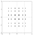
- FIG. 36 is a diagram showing an embodiment of NUQ-64 for 6/15 code rate according to the present invention.
- FIG. 37 is a diagram showing an embodiment of NUQ-64 for 7/15 code rate according to the present invention.
- FIG. 38 is a diagram showing an embodiment of NUQ-64 for 8/15 code rate according to the present invention.
- FIG. 39 is a diagram showing an embodiment of NUQ-64 for 9/15 and 10/15 code rates according to the present invention.
- FIG. 40 is a diagram showing an embodiment of NUQ-64 for 11/15 code rate according to the present invention.
- FIG. 41 is a diagram showing an embodiment of NUQ-64 for 12/15 code rate according to the present invention.
- FIG. 42 is a diagram showing an embodiment of NUQ-64 for 13/15 code rate according to the present invention.
- FIG. 43 is a method of transmitting broadcast signals according to an embodiment of the present invention.
- FIG. 44 is a method of receiving broadcast signals according to an embodiment of the present invention.
- the present invention provides apparatuses and methods for transmitting and receiving broadcast signals for future broadcast services.
- Future broadcast services include a terrestrial broadcast service, a mobile broadcast service, a UHDTV service, etc.
- the present invention may process broadcast signals for the future broadcast services through non-MIMO (Multiple Input Multiple Output) or MIMO according to one embodiment.
- a non-MIMO scheme according to an embodiment of the present invention may include a MISO (Multiple Input Single Output) scheme, a SISO (Single Input Single Output) scheme, etc.
- MISO or MIMO uses two antennas in the following for convenience of description, the present invention is applicable to systems using two or more antennas.
- the present invention may defines three physical layer (PL) profiles - base, handheld and advanced profiles - each optimized to minimize receiver complexity while attaining the performance required for a particular use case.
- the physical layer (PHY) profiles are subsets of all configurations that a corresponding receiver should implement.
- the three PHY profiles share most of the functional blocks but differ slightly in specific blocks and/or parameters. Additional PHY profiles can be defined in the future. For the system evolution, future profiles can also be multiplexed with the existing profiles in a single RF channel through a future extension frame (FEF). The details of each PHY profile are described below.
- FEF future extension frame
- the base profile represents a main use case for fixed receiving devices that are usually connected to a roof-top antenna.
- the base profile also includes portable devices that could be transported to a place but belong to a relatively stationary reception category. Use of the base profile could be extended to handheld devices or even vehicular by some improved implementations, but those use cases are not expected for the base profile receiver operation.
- Target SNR range of reception is from approximately 10 to 20dB, which includes the 15dB SNR reception capability of the existing broadcast system (e.g. ATSC A/53).
- the receiver complexity and power consumption is not as critical as in the battery-operated handheld devices, which will use the handheld profile. Key system parameters for the base profile are listed in below table 1.
- Table 1 LDPC codeword length 16K, 64K bits Constellation size 4 ⁇ 10 bpcu (bits per channel use) Time de-interleaving memory size 2 19 data cells Pilot patterns Pilot pattern for fixed reception FFT size 16K, 32K points
- the handheld profile is designed for use in handheld and vehicular devices that operate with battery power.
- the devices can be moving with pedestrian or vehicle speed.
- the power consumption as well as the receiver complexity is very important for the implementation of the devices of the handheld profile.
- the target SNR range of the handheld profile is approximately 0 to 10dB, but can be configured to reach below 0dB when intended for deeper indoor reception.
- Table 2 LDPC codeword length 16K bits Constellation size 2 ⁇ 8 bpcu Time de-interleaving memory size 2 18 data cells Pilot patterns Pilot patterns for mobile and indoor reception FFT size 8K, 16K points
- the advanced profile provides highest channel capacity at the cost of more implementation complexity.
- This profile requires using MIMO transmission and reception, and UHDTV service is a target use case for which this profile is specifically designed.
- the increased capacity can also be used to allow an increased number of services in a given bandwidth, e.g., multiple SDTV or HDTV services.
- the target SNR range of the advanced profile is approximately 20 to 30dB.
- MIMO transmission may initially use existing elliptically-polarized transmission equipment, with extension to full-power cross-polarized transmission in the future.
- Key system parameters for the advanced profile are listed in below table 3.
- Table 3 LDPC codeword length 16K, 64K bits Constellation size 8 ⁇ 12 bpcu Time de-interleaving memory size 2 19 data cells Pilot patterns Pilot pattern for fixed reception FFT size 16K, 32K points
- FIG. 1 illustrates a structure of an apparatus for transmitting broadcast signals for future broadcast services according to an embodiment of the present invention.
- the apparatus for transmitting broadcast signals for future broadcast services can include an input formatting block 1000, a BICM (Bit interleaved coding & modulation) block 1010, a frame structure block 1020, an OFDM (Orthogonal Frequency Division Multiplexing) generation block 1030 and a signaling generation block 1040.
- BICM Bit interleaved coding & modulation
- OFDM Orthogonal Frequency Division Multiplexing
- IP stream/packets and MPEG2-TS are the main input formats, other stream types are handled as General Streams.
- Management Information is input to control the scheduling and allocation of the corresponding bandwidth for each input stream.
- One or multiple TS stream(s), IP stream(s) and/or General Stream(s) inputs are simultaneously allowed.
- the input formatting block 1000 can demultiplex each input stream into one or multiple data pipe(s), to each of which an independent coding and modulation is applied.
- the data pipe (DP) is the basic unit for robustness control, thereby affecting quality-of-service (QoS).
- QoS quality-of-service
- One or multiple service(s) or service component(s) can be carried by a single DP. Details of operations of the input formatting block 1000 will be described later.
- the data pipe is a logical channel in the physical layer that carries service data or related metadata, which may carry one or multiple service(s) or service component(s).
- the data pipe unit a basic unit for allocating data cells to a DP in a frame.
- parity data is added for error correction and the encoded bit streams are mapped to complex-value constellation symbols.
- the symbols are interleaved across a specific interleaving depth that is used for the corresponding DP.
- MIMO encoding is performed in the BICM block 1010 and the additional data path is added at the output for MIMO transmission. Details of operations of the BICM block 1010 will be described later.
- the Frame Building block 1020 can map the data cells of the input DPs into the OFDM symbols within a frame. After mapping, the frequency interleaving is used for frequency-domain diversity, especially to combat frequency-selective fading channels. Details of operations of the Frame Building block 1020 will be described later.
- the OFDM Generation block 1030 can apply conventional OFDM modulation having a cyclic prefix as guard interval. For antenna space diversity, a distributed MISO scheme is applied across the transmitters. In addition, a Peak-to-Average Power Reduction (PAPR) scheme is performed in the time domain. For flexible network planning, this proposal provides a set of various FFT sizes, guard interval lengths and corresponding pilot patterns. Details of operations of the OFDM Generation block 1030 will be described later.
- PAPR Peak-to-Average Power Reduction
- the Signaling Generation block 1040 can create physical layer signaling information used for the operation of each functional block. This signaling information is also transmitted so that the services of interest are properly recovered at the receiver side. Details of operations of the Signaling Generation block 1040 will be described later.
- FIGS. 2, 3 and 4 illustrate the input formatting block 1000 according to embodiments of the present invention. A description will be given of each figure.
- FIG. 2 illustrates an input formatting block according to one embodiment of the present invention.
- FIG. 2 shows an input formatting module when the input signal is a single input stream.
- the input formatting block illustrated in FIG. 2 corresponds to an embodiment of the input formatting block 1000 described with reference to FIG. 1.
- the input to the physical layer may be composed of one or multiple data streams. Each data stream is carried by one DP.
- the mode adaptation modules slice the incoming data stream into data fields of the baseband frame (BBF).
- BBF baseband frame
- the system supports three types of input data streams: MPEG2-TS, Internet protocol (IP) and Generic stream (GS).
- MPEG2-TS is characterized by fixed length (188 byte) packets with the first byte being a sync-byte (0x47).
- An IP stream is composed of variable length IP datagram packets, as signaled within IP packet headers.
- the system supports both IPv4 and IPv6 for the IP stream.
- GS may be composed of variable length packets or constant length packets, signaled within encapsulation packet headers.
- the Input Stream Splitter splits the input TS, IP, GS streams into multiple service or service component (audio, video, etc.) streams.
- the mode adaptation module 2010 is comprised of a CRC Encoder, BB (baseband) Frame Slicer, and BB Frame Header Insertion block.
- the CRC Encoder provides three kinds of CRC encoding for error detection at the user packet (UP) level, i.e., CRC-8, CRC-16, and CRC-32.
- the computed CRC bytes are appended after the UP.
- CRC-8 is used for TS stream and CRC-32 for IP stream. If the GS stream doesn't provide the CRC encoding, the proposed CRC encoding should be applied.
- the BB Frame Slicer maps the input into an internal logical-bit format.
- the first received bit is defined to be the MSB.
- the BB Frame Slicer allocates a number of input bits equal to the available data field capacity.
- the UP packet stream is sliced to fit the data field of BBF.
- BB Frame Header Insertion block can insert fixed length BBF header of 2 bytes is inserted in front of the BB Frame.
- the BBF header is composed of STUFFI (1 bit), SYNCD (13 bits), and RFU (2 bits).
- BBF can have an extension field (1 or 3 bytes) at the end of the 2-byte BBF header.
- the stream adaptation 2010 is comprised of stuffing insertion block and BB scrambler.
- the stuffing insertion block can insert stuffing field into a payload of a BB frame. If the input data to the stream adaptation is sufficient to fill a BB-Frame, STUFFI is set to '0' and the BBF has no stuffing field. Otherwise STUFFI is set to '1' and the stuffing field is inserted immediately after the BBF header.
- the stuffing field comprises two bytes of the stuffing field header and a variable size of stuffing data.
- the BB scrambler scrambles complete BBF for energy dispersal.
- the scrambling sequence is synchronous with the BBF.
- the scrambling sequence is generated by the feed-back shift register.
- the PLS generation block 2020 can generate physical layer signaling (PLS) data.
- PLS provides the receiver with a means to access physical layer DPs.
- the PLS data consists of PLS1 data and PLS2 data.
- the PLS1 data is a first set of PLS data carried in the FSS symbols in the frame having a fixed size, coding and modulation, which carries basic information about the system as well as the parameters needed to decode the PLS2 data.
- the PLS1 data provides basic transmission parameters including parameters required to enable the reception and decoding of the PLS2 data. Also, the PLS1 data remains constant for the duration of a frame-group.
- the PLS2 data is a second set of PLS data transmitted in the FSS symbol, which carries more detailed PLS data about the system and the DPs.
- the PLS2 contains parameters that provide sufficient information for the receiver to decode the desired DP.
- the PLS2 signaling further consists of two types of parameters, PLS2 Static data (PLS2-STAT data) and PLS2 dynamic data (PLS2-DYN data).
- PLS2 Static data is PLS2 data that remains static for the duration of a frame-group and the PLS2 dynamic data is PLS2 data that may dynamically change frame-by-frame.
- the PLS scrambler 2030 can scramble the generated PLS data for energy dispersal.
- FIG. 3 illustrates an input formatting block according to another embodiment of the present invention.
- the input formatting block illustrated in FIG. 3 corresponds to an embodiment of the input formatting block 1000 described with reference to FIG. 1.
- FIG. 3 shows a mode adaptation block of the input formatting block when the input signal corresponds to multiple input streams.
- the mode adaptation block of the input formatting block for processing the multiple input streams can independently process the multiple input streams.
- the mode adaptation block for respectively processing the multiple input streams can include an input stream splitter 3000, an input stream synchronizer 3010, a compensating delay block 3020, a null packet deletion block 3030, a head compression block 3040, a CRC encoder 3050, a BB frame slicer 3060 and a BB header insertion block 3070. Description will be given of each block of the mode adaptation block.
- Operations of the CRC encoder 3050, BB frame slicer 3060 and BB header insertion block 3070 correspond to those of the CRC encoder, BB frame slicer and BB header insertion block described with reference to FIG. 2 and thus description thereof is omitted.
- the input stream splitter 3000 can split the input TS, IP, GS streams into multiple service or service component (audio, video, etc.) streams.
- the input stream synchronizer 3010 may be referred as ISSY.
- the ISSY can provide suitable means to guarantee Constant Bit Rate (CBR) and constant end-to-end transmission delay for any input data format.
- CBR Constant Bit Rate
- the ISSY is always used for the case of multiple DPs carrying TS, and optionally used for multiple DPs carrying GS streams.
- the compensating delay block 3020 can delay the split TS packet stream following the insertion of ISSY information to allow a TS packet recombining mechanism without requiring additional memory in the receiver.
- the null packet deletion block 3030 is used only for the TS input stream case.
- Some TS input streams or split TS streams may have a large number of null-packets present in order to accommodate VBR (variable bit-rate) services in a CBR TS stream.
- null-packets can be identified and not transmitted.
- removed null-packets can be re-inserted in the exact place where they were originally by reference to a deleted null-packet (DNP) counter that is inserted in the transmission, thus guaranteeing constant bit-rate and avoiding the need for time-stamp (PCR) updating.
- DNP deleted null-packet
- the head compression block 3040 can provide packet header compression to increase transmission efficiency for TS or IP input streams. Because the receiver can have a priori information on certain parts of the header, this known information can be deleted in the transmitter.
- the receiver For Transport Stream, the receiver has a-priori information about the sync-byte configuration (0x47) and the packet length (188 Byte). If the input TS stream carries content that has only one PID, i.e., for only one service component (video, audio, etc.) or service sub-component (SVC base layer, SVC enhancement layer, MVC base view or MVC dependent views), TS packet header compression can be applied (optionally) to the Transport Stream. IP packet header compression is used optionally if the input steam is an IP stream.
- FIG. 4 illustrates an input formatting block according to another embodiment of the present invention.
- the input formatting block illustrated in FIG. 4 corresponds to an embodiment of the input formatting block 1000 described with reference to FIG. 1.
- FIG. 4 illustrates a stream adaptation block of the input formatting module when the input signal corresponds to multiple input streams.
- the mode adaptation block for respectively processing the multiple input streams can include a scheduler 4000, an 1-Frame delay block 4010, a stuffing insertion block 4020, an in-band signaling 4030, a BB Frame scrambler 4040, a PLS generation block 4050 and a PLS scrambler 4060. Description will be given of each block of the stream adaptation block.
- Operations of the stuffing insertion block 4020, the BB Frame scrambler 4040, the PLS generation block 4050 and the PLS scrambler 4060 correspond to those of the stuffing insertion block, BB scrambler, PLS generation block and the PLS scrambler described with reference to FIG. 2 and thus description thereof is omitted.
- the scheduler 4000 can determine the overall cell allocation across the entire frame from the amount of FECBLOCKs of each DP. Including the allocation for PLS, EAC and FIC, the scheduler generate the values of PLS2-DYN data, which is transmitted as in-band signaling or PLS cell in FSS of the frame. Details of FECBLOCK, EAC and FIC will be described later.
- the 1-Frame delay block 4010 can delay the input data by one transmission frame such that scheduling information about the next frame can be transmitted through the current frame for in-band signaling information to be inserted into the DPs.
- the in-band signaling 4030 can insert un-delayed part of the PLS2 data into a DP of a frame.
- FIG. 5 illustrates a BICM block according to an embodiment of the present invention.
- the BICM block illustrated in FIG. 5 corresponds to an embodiment of the BICM block 1010 described with reference to FIG. 1.
- the apparatus for transmitting broadcast signals for future broadcast services can provide a terrestrial broadcast service, mobile broadcast service, UHDTV service, etc.
- the a BICM block according to an embodiment of the present invention can independently process DPs input thereto by independently applying SISO, MISO and MIMO schemes to the data pipes respectively corresponding to data paths. Consequently, the apparatus for transmitting broadcast signals for future broadcast services according to an embodiment of the present invention can control QoS for each service or service component transmitted through each DP.
- the BICM block shared by the base profile and the handheld profile and the BICM block of the advanced profile can include plural processing blocks for processing each DP.
- a processing block 5000 of the BICM block for the base profile and the handheld profile can include a Data FEC encoder 5010, a bit interleaver 5020, a constellation mapper 5030, an SSD (Signal Space Diversity) encoding block 5040 and a time interleaver 5050.
- the Data FEC encoder 5010 can perform the FEC encoding on the input BBF to generate FECBLOCK procedure using outer coding (BCH), and inner coding (LDPC).
- BCH outer coding
- LDPC inner coding
- the outer coding (BCH) is optional coding method. Details of operations of the Data FEC encoder 5010 will be described later.
- the bit interleaver 5020 can interleave outputs of the Data FEC encoder 5010 to achieve optimized performance with combination of the LDPC codes and modulation scheme while providing an efficiently implementable structure. Details of operations of the bit interleaver 5020 will be described later.
- the constellation mapper 5030 can modulate each cell word from the bit interleaver 5020 in the base and the handheld profiles, or cell word from the Cell-word demultiplexer 5010-1 in the advanced profile using either QPSK, QAM-16, non-uniform QAM (NUQ-64, NUQ-256, NUQ-1024) or non-uniform constellation (NUC-16, NUC-64, NUC-256, NUC-1024) to give a power-normalized constellation point, e l .
- This constellation mapping is applied only for DPs. Observe that QAM-16 and NUQs are square shaped, while NUCs have arbitrary shape. When each constellation is rotated by any multiple of 90 degrees, the rotated constellation exactly overlaps with its original one.
- the SSD encoding block 5040 can precode cells in two (2D), three (3D), and four (4D) dimensions to increase the reception robustness under difficult fading conditions.
- the time interleaver 5050 can operates at the DP level.
- the parameters of time interleaving (TI) may be set differently for each DP. Details of operations of the time interleaver 5050 will be described later.
- a processing block 5000-1 of the BICM block for the advanced profile can include the Data FEC encoder, bit interleaver, constellation mapper, and time interleaver. However, the processing block 5000-1 is distinguished from the processing block 5000 further includes a cell-word demultiplexer 5010-1 and a MIMO encoding block 5020-1.
- the operations of the Data FEC encoder, bit interleaver, constellation mapper, and time interleaver in the processing block 5000-1 correspond to those of the Data FEC encoder 5010, bit interleaver 5020, constellation mapper 5030, and time interleaver 5050 described and thus description thereof is omitted.
- the cell-word demultiplexer 5010-1 is used for the DP of the advanced profile to divide the single cell-word stream into dual cell-word streams for MIMO processing. Details of operations of the cell-word demultiplexer 5010-1 will be described later.
- the MIMO encoding block 5020-1 can processing the output of the cell-word demultiplexer 5010-1 using MIMO encoding scheme.
- the MIMO encoding scheme was optimized for broadcasting signal transmission.
- the MIMO technology is a promising way to get a capacity increase but it depends on channel characteristics. Especially for broadcasting, the strong LOS component of the channel or a difference in the received signal power between two antennas caused by different signal propagation characteristics makes it difficult to get capacity gain from MIMO.
- the proposed MIMO encoding scheme overcomes this problem using a rotation-based pre-coding and phase randomization of one of the MIMO output signals.
- MIMO encoding is intended for a 2x2 MIMO system requiring at least two antennas at both the transmitter and the receiver.
- Two MIMO encoding modes are defined in this proposal; full-rate spatial multiplexing (FR-SM) and full-rate full-diversity spatial multiplexing (FRFD-SM).
- FR-SM full-rate spatial multiplexing
- FRFD-SM full-rate full-diversity spatial multiplexing
- the FR-SM encoding provides capacity increase with relatively small complexity increase at the receiver side while the FRFD-SM encoding provides capacity increase and additional diversity gain with a great complexity increase at the receiver side.
- the proposed MIMO encoding scheme has no restriction on the antenna polarity configuration.
- MIMO processing is required for the advanced profile frame, which means all DPs in the advanced profile frame are processed by the MIMO encoder. MIMO processing is applied at DP level. Pairs of the Constellation Mapper outputs NUQ ( e 1,i and e 2,i ) are fed to the input of the MIMO Encoder. Paired MIMO Encoder output (g1,i and g2,i) is transmitted by the same carrier k and OFDM symbol l of their respective TX antennas.
- FIG. 6 illustrates a BICM block according to another embodiment of the present invention.
- the BICM block illustrated in FIG. 6 corresponds to an embodiment of the BICM block 1010 described with reference to FIG. 1.
- FIG. 6 illustrates a BICM block for protection of physical layer signaling (PLS), emergency alert channel (EAC) and fast information channel (FIC).
- PLS physical layer signaling
- EAC emergency alert channel
- FIC fast information channel
- the BICM block for protection of PLS, EAC and FIC can include a PLS FEC encoder 6000, a bit interleaver 6010, a constellation mapper 6020 and time interleaver 6030.
- the PLS FEC encoder 6000 can include a scrambler, BCH encoding/zero insertion block, LDPC encoding block and LDPC parity punturing block. Description will be given of each block of the BICM block.
- the PLS FEC encoder 6000 can encode the scrambled PLS 1/2 data, EAC and FIC section.
- the scrambler can scramble PLS1 data and PLS2 data before BCH encoding and shortened and punctured LDPC encoding.
- the BCH encoding/zero insertion block can perform outer encoding on the scrambled PLS 1/2 data using the shortened BCH code for PLS protection and insert zero bits after the BCH encoding.
- the output bits of the zero insertion may be permutted before LDPC encoding.
- the LDPC encoding block can encode the output of the BCH encoding/zero insertion block using LDPC code.
- C ldpc parity bits
- P ldpc parity bits
- I ldpc appended after it.
- the LDPC code parameters for PLS1 and PLS2 are as following table 4.
- the LDPC parity punturing block can perform puncturing on the PLS1 data and PLS 2 data.
- the bit interleaver 6010 can interleave the each shortened and punctured PLS1 data and PLS2 data.
- the constellation mapper 6020 can map the bit ineterlaeved PLS1 data and PLS2 data onto constellations.
- the time interleaver 6030 can interleave the mapped PLS1 data and PLS2 data.
- FIG. 7 illustrates a frame building block according to one embodiment of the present invention.
- the frame building block illustrated in FIG. 7 corresponds to an embodiment of the frame building block 1020 described with reference to FIG. 1.
- the frame building block can include a delay compensation block 7000, a cell mapper 7010 and a frequency interleaver 7020. Description will be given of each block of the frame building block.
- the delay compensation block 7000 can adjust the timing between the data pipes and the corresponding PLS data to ensure that they are co-timed at the transmitter end.
- the PLS data is delayed by the same amount as data pipes are by addressing the delays of data pipes caused by the Input Formatting block and BICM block.
- the delay of the BICM block is mainly due to the time interleaver.
- In-band signaling data carries information of the next TI group so that they are carried one frame ahead of the DPs to be signaled.
- the Delay Compensating block delays in-band signaling data accordingly.
- the cell mapper 7010 can map PLS, EAC, FIC, DPs, auxiliary streams and dummy cells into the active carriers of the OFDM symbols in the frame. Details of the frame will be described later.
- the frequency interleaver 7020 can randomly interleave data cells received from the cell mapper 7010 to provide frequency diversity. Also, the frequency interleaver 7020 can operate on very OFDM symbol pair comprised of two sequential OFDM symbols using a different interleaving-seed order to get maximum interleaving gain in a single frame. Details of operations of the frequency interleaver 7020 will be described later.
- FIG. 8 illustrates an OFMD generation block according to an embodiment of the present invention.
- the OFMD generation block illustrated in FIG. 8 corresponds to an embodiment of the OFMD generation block 1030 described with reference to FIG. 1.
- the OFDM generation block modulates the OFDM carriers by the cells produced by the Frame Building block, inserts the pilots, and produces the time domain signal for transmission. Also, this block subsequently inserts guard intervals, and applies PAPR (Peak-to-Average Power Radio) reduction processing to produce the final RF signal.
- PAPR Peak-to-Average Power Radio
- the frame building block can include a pilot and reserved tone insertion block 8000, a 2D-eSFN encoding block 8010, an IFFT (Inverse Fast Fourier Transform) block 8020, a PAPR reduction block 8030, a guard interval insertion block 8040, a preamble insertion block 8050, other system insertion block 8060 and a DAC block 8070. Description will be given of each block of the frame building block.
- IFFT Inverse Fast Fourier Transform
- the pilot and reserved tone insertion block 8000 can insert pilots and the reserved tone.
- pilots which have transmitted values known a priori in the receiver.
- the information of pilot cells is made up of scattered pilots, continual pilots, edge pilots, FSS (frame signaling symbol) pilots and FES (frame edge symbol) pilots.
- Each pilot is transmitted at a particular boosted power level according to pilot type and pilot pattern.
- the value of the pilot information is derived from a reference sequence, which is a series of values, one for each transmitted carrier on any given symbol.
- the pilots can be used for frame synchronization, frequency synchronization, time synchronization, channel estimation, and transmission mode identification, and also can be used to follow the phase noise.
- Reference information, taken from the reference sequence, is transmitted in scattered pilot cells in every symbol except the preamble, FSS and FES of the frame.
- Continual pilots are inserted in every symbol of the frame. The number and location of continual pilots depends on both the FFT size and the scattered pilot pattern.
- the edge carriers are edge pilots in every symbol except for the preamble symbol. They are inserted in order to allow frequency interpolation up to the edge of the spectrum.
- FSS pilots are inserted in FSS(s) and FES pilots are inserted in FES. They are inserted in order to allow time interpolation up to the edge of the frame.
- the system according to an embodiment of the present invention supports the SFN network, where distributed MISO scheme is optionally used to support very robust transmission mode.
- the 2D-eSFN is a distributed MISO scheme that uses multiple TX antennas, each of which is located in the different transmitter site in the SFN network.
- the 2D-eSFN encoding block 8010 can process a 2D-eSFN processing to distorts the phase of the signals transmitted from multiple transmitters, in order to create both time and frequency diversity in the SFN configuration. Hence, burst errors due to low flat fading or deep-fading for a long time can be mitigated.
- the IFFT block 8020 can modulate the output from the 2D-eSFN encoding block 8010 using OFDM modulation scheme. Any cell in the data symbols which has not been designated as a pilot (or as a reserved tone) carries one of the data cells from the frequency interleaver. The cells are mapped to OFDM carriers.
- the PAPR reduction block 8030 can perform a PAPR reduction on input signal using various PAPR reduction algorithm in the time domain.
- the guard interval insertion block 8040 can insert guard intervals and the preamble insertion block 8050 can insert preamble in front of the signal. Details of a structure of the preamble will be described later.
- the other system insertion block 8060 can multiplex signals of a plurality of broadcast transmission/reception systems in the time domain such that data of two or more different broadcast transmission/reception systems providing broadcast services can be simultaneously transmitted in the same RF signal bandwidth.
- the two or more different broadcast transmission/reception systems refer to systems providing different broadcast services.
- the different broadcast services may refer to a terrestrial broadcast service, mobile broadcast service, etc. Data related to respective broadcast services can be transmitted through different frames.
- the DAC block 8070 can convert an input digital signal into an analog signal and output the analog signal.
- the signal output from the DAC block 7800 can be transmitted through multiple output antennas according to the physical layer profiles.
- a Tx antenna according to an embodiment of the present invention can have vertical or horizontal polarity.
- FIG. 9 illustrates a structure of an apparatus for receiving broadcast signals for future broadcast services according to an embodiment of the present invention.
- the apparatus for receiving broadcast signals for future broadcast services can correspond to the apparatus for transmitting broadcast signals for future broadcast services, described with reference to FIG. 1.
- the apparatus for receiving broadcast signals for future broadcast services can include a synchronization & demodulation module 9000, a frame parsing module 9010, a demapping & decoding module 9020, an output processor 9030 and a signaling decoding module 9040. A description will be given of operation of each module of the apparatus for receiving broadcast signals.
- the synchronization & demodulation module 9000 can receive input signals through m Rx antennas, perform signal detection and synchronization with respect to a system corresponding to the apparatus for receiving broadcast signals and carry out demodulation corresponding to a reverse procedure of the procedure performed by the apparatus for transmitting broadcast signals.
- the frame parsing module 9100 can parse input signal frames and extract data through which a service selected by a user is transmitted. If the apparatus for transmitting broadcast signals performs interleaving, the frame parsing module 9100 can carry out deinterleaving corresponding to a reverse procedure of interleaving. In this case, the positions of a signal and data that need to be extracted can be obtained by decoding data output from the signaling decoding module 9400 to restore scheduling information generated by the apparatus for transmitting broadcast signals.
- the demapping & decoding module 9200 can convert the input signals into bit domain data and then deinterleave the same as necessary.
- the demapping & decoding module 9200 can perform demapping for mapping applied for transmission efficiency and correct an error generated on a transmission channel through decoding. In this case, the demapping & decoding module 9200 can obtain transmission parameters necessary for demapping and decoding by decoding the data output from the signaling decoding module 9400.
- the output processor 9300 can perform reverse procedures of various compression/signal processing procedures which are applied by the apparatus for transmitting broadcast signals to improve transmission efficiency.
- the output processor 9300 can acquire necessary control information from data output from the signaling decoding module 9400.
- the output of the output processor 8300 corresponds to a signal input to the apparatus for transmitting broadcast signals and may be MPEG-TSs, IP streams (v4 or v6) and generic streams.
- the signaling decoding module 9400 can obtain PLS information from the signal demodulated by the synchronization & demodulation module 9000. As described above, the frame parsing module 9100, demapping & decoding module 9200 and output processor 9300 can execute functions thereof using the data output from the signaling decoding module 9400.
- FIG. 10 illustrates a frame structure according to an embodiment of the present invention.
- FIG. 10 shows an example configuration of the frame types and FRUs in a super-frame.
- (a) shows a super frame according to an embodiment of the present invention
- (b) shows FRU (Frame Repetition Unit) according to an embodiment of the present invention
- (c) shows frames of variable PHY profiles in the FRU
- (d) shows a structure of a frame.
- a super-frame may be composed of eight FRUs.
- the FRU is a basic multiplexing unit for TDM of the frames, and is repeated eight times in a super-frame.
- Each frame in the FRU belongs to one of the PHY profiles, (base, handheld, advanced) or FEF.
- the maximum allowed number of the frames in the FRU is four and a given PHY profile can appear any number of times from zero times to four times in the FRU (e.g., base, base, handheld, advanced).
- PHY profile definitions can be extended using reserved values of the PHY_PROFILE in the preamble, if required.
- the FEF part is inserted at the end of the FRU, if included.
- the minimum number of FEFs is 8 in a super-frame. It is not recommended that FEF parts be adjacent to each other.
- One frame is further divided into a number of OFDM symbols and a preamble. As shown in (d), the frame comprises a preamble, one or more frame signaling symbols (FSS), normal data symbols and a frame edge symbol (FES).
- FSS frame signaling symbols
- FES normal data symbols
- FES frame edge symbol
- the preamble is a special symbol that enables fast Futurecast UTB system signal detection and provides a set of basic transmission parameters for efficient transmission and reception of the signal. The detailed description of the preamble will be will be described later.
- the main purpose of the FSS(s) is to carry the PLS data.
- the FSS For fast synchronization and channel estimation, and hence fast decoding of PLS data, the FSS has more dense pilot pattern than the normal data symbol.
- the FES has exactly the same pilots as the FSS, which enables frequency-only interpolation within the FES and temporal interpolation, without extrapolation, for symbols immediately preceding the FES.
- FIG. 11 illustrates a signaling hierarchy structure of the frame according to an embodiment of the present invention.
- FIG. 11 illustrates the signaling hierarchy structure, which is split into three main parts: the preamble signaling data 11000, the PLS1 data 11010 and the PLS2 data 11020.
- the purpose of the preamble which is carried by the preamble symbol in every frame, is to indicate the transmission type and basic transmission parameters of that frame.
- the PLS1 enables the receiver to access and decode the PLS2 data, which contains the parameters to access the DP of interest.
- the PLS2 is carried in every frame and split into two main parts: PLS2-STAT data and PLS2-DYN data. The static and dynamic portion of PLS2 data is followed by padding, if necessary.
- FIG. 12 illustrates preamble signaling data according to an embodiment of the present invention.
- Preamble signaling data carries 21 bits of information that are needed to enable the receiver to access PLS data and trace DPs within the frame structure. Details of the preamble signaling data are as follows:
- PHY_PROFILE This 3-bit field indicates the PHY profile type of the current frame. The mapping of different PHY profile types is given in below table 5.
- FFT_SIZE This 2 bit field indicates the FFT size of the current frame within a frame-group, as described in below table 6.
- GI_FRACTION This 3 bit field indicates the guard interval fraction value in the current super-frame, as described in below table 7.
- EAC_FLAG This 1 bit field indicates whether the EAC is provided in the current frame. If this field is set to '1', emergency alert service (EAS) is provided in the current frame. If this field set to '0', EAS is not carried in the current frame. This field can be switched dynamically within a super-frame.
- EAS emergency alert service
- PILOT_MODE This 1-bit field indicates whether the pilot mode is mobile mode or fixed mode for the current frame in the current frame-group. If this field is set to '0', mobile pilot mode is used. If the field is set to '1', the fixed pilot mode is used.
- PAPR_FLAG This 1-bit field indicates whether PAPR reduction is used for the current frame in the current frame-group. If this field is set to value '1', tone reservation is used for PAPR reduction. If this field is set to '0', PAPR reduction is not used.
- FRU_CONFIGURE This 3-bit field indicates the PHY profile type configurations of the frame repetition units (FRU) that are present in the current super-frame. All profile types conveyed in the current super-frame are identified in this field in all preambles in the current super-frame.
- the 3-bit field has a different definition for each profile, as show in below table 8.
- FIG. 13 illustrates PLS1 data according to an embodiment of the present invention.
- PLS1 data provides basic transmission parameters including parameters required to enable the reception and decoding of the PLS2. As above mentioned, the PLS1 data remain unchanged for the entire duration of one frame-group.
- the detailed definition of the signaling fields of the PLS1 data are as follows:
- PREAMBLE_DATA This 20-bit field is a copy of the preamble signaling data excluding the EAC_FLAG.
- NUM_FRAME_FRU This 2-bit field indicates the number of the frames per FRU.
- PAYLOAD_TYPE This 3-bit field indicates the format of the payload data carried in the frame-group. PAYLOAD_TYPE is signaled as shown in table 9.
- NUM_FSS This 2-bit field indicates the number of FSS symbols in the current frame.
- SYSTEM_VERSION This 8-bit field indicates the version of the transmitted signal format.
- the SYSTEM_VERSION is divided into two 4-bit fields, which are a major version and a minor version.
- MSB four bits of SYSTEM_VERSION field indicate major version information.
- a change in the major version field indicates a non-backward-compatible change.
- the default value is '0000'.
- the value is set to '0000'.
- Minor version The LSB four bits of SYSTEM_VERSION field indicate minor version information. A change in the minor version field is backward-compatible.
- CELL_ID This is a 16-bit field which uniquely identifies a geographic cell in an ATSC network.
- An ATSC cell coverage area may consist of one or more frequencies, depending on the number of frequencies used per Futurecast UTB system. If the value of the CELL_ID is not known or unspecified, this field is set to '0'.
- NETWORK_ID This is a 16-bit field which uniquely identifies the current ATSC network.
- SYSTEM_ID This 16-bit field uniquely identifies the Futurecast UTB system within the ATSC network.
- the Futurecast UTB system is the terrestrial broadcast system whose input is one or more input streams (TS, IP, GS) and whose output is an RF signal.
- the Futurecast UTB system carries one or more PHY profiles and FEF, if any.
- the same Futurecast UTB system may carry different input streams and use different RF frequencies in different geographical areas, allowing local service insertion.
- the frame structure and scheduling is controlled in one place and is identical for all transmissions within a Futurecast UTB system.
- One or more Futurecast UTB systems may have the same SYSTEM_ID meaning that they all have the same physical layer structure and configuration.
- the following loop consists of FRU_PHY_PROFILE, FRU_FRAME_LENGTH, FRU_GI_FRACTION, and RESERVED which are used to indicate the FRU configuration and the length of each frame type.
- the loop size is fixed so that four PHY profiles (including a FEF) are signaled within the FRU. If NUM_FRAME_FRU is less than 4, the unused fields are filled with zeros.
- FRU_PHY_PROFILE This 3-bit field indicates the PHY profile type of the ( i +1) th ( i is the loop index) frame of the associated FRU. This field uses the same signaling format as shown in the table 8.
- FRU_FRAME_LENGTH This 2-bit field indicates the length of the ( i +1) th frame of the associated FRU. Using FRU_FRAME_LENGTH together with FRU_GI_FRACTION, the exact value of the frame duration can be obtained.
- FRU_GI_FRACTION This 3-bit field indicates the guard interval fraction value of the ( i +1) th frame of the associated FRU.
- FRU_GI_FRACTION is signaled according to the table 7.
- the following fields provide parameters for decoding the PLS2 data.
- PLS2_FEC_TYPE This 2-bit field indicates the FEC type used by the PLS2 protection.
- the FEC type is signaled according to table 10. The details of the LDPC codes will be described later.
- PLS2_MOD This 3-bit field indicates the modulation type used by the PLS2. The modulation type is signaled according to table 11.
- PLS2_SIZE_CELL This 15-bit field indicates C total_partial_block , the size (specified as the number of QAM cells) of the collection of full coded blocks for PLS2 that is carried in the current frame-group. This value is constant during the entire duration of the current frame-group.
- PLS2_STAT_SIZE_BIT This 14-bit field indicates the size, in bits, of the PLS2-STAT for the current frame-group. This value is constant during the entire duration of the current frame-group.
- PLS2_DYN_SIZE_BIT This 14-bit field indicates the size, in bits, of the PLS2-DYN for the current frame-group. This value is constant during the entire duration of the current frame-group.
- PLS2_REP_FLAG This 1-bit flag indicates whether the PLS2 repetition mode is used in the current frame-group. When this field is set to value '1', the PLS2 repetition mode is activated. When this field is set to value '0', the PLS2 repetition mode is deactivated.
- PLS2_REP_SIZE_CELL This 15-bit field indicates C total_partial_block , the size (specified as the number of QAM cells) of the collection of partial coded blocks for PLS2 carried in every frame of the current frame-group, when PLS2 repetition is used. If repetition is not used, the value of this field is equal to 0. This value is constant during the entire duration of the current frame-group.
- PLS2_NEXT_FEC_TYPE This 2-bit field indicates the FEC type used for PLS2 that is carried in every frame of the next frame-group. The FEC type is signaled according to the table 10.
- PLS2_NEXT_MOD This 3-bit field indicates the modulation type used for PLS2 that is carried in every frame of the next frame-group. The modulation type is signaled according to the table 11.
- PLS2_NEXT_REP_FLAG This 1-bit flag indicates whether the PLS2 repetition mode is used in the next frame-group. When this field is set to value '1', the PLS2 repetition mode is activated. When this field is set to value '0', the PLS2 repetition mode is deactivated.
- PLS2_NEXT_REP_SIZE_CELL This 15-bit field indicates C total_full_block , The size (specified as the number of QAM cells) of the collection of full coded blocks for PLS2 that is carried in every frame of the next frame-group, when PLS2 repetition is used. If repetition is not used in the next frame-group, the value of this field is equal to 0. This value is constant during the entire duration of the current frame-group.
- PLS2_NEXT_REP_STAT_SIZE_BIT This 14-bit field indicates the size, in bits, of the PLS2-STAT for the next frame-group. This value is constant in the current frame-group.
- PLS2_NEXT_REP_DYN_SIZE_BIT This 14-bit field indicates the size, in bits, of the PLS2-DYN for the next frame-group. This value is constant in the current frame-group.
- PLS2_AP_MODE This 2-bit field indicates whether additional parity is provided for PLS2 in the current frame-group. This value is constant during the entire duration of the current frame-group. The below table 12 gives the values of this field. When this field is set to '00', additional parity is not used for the PLS2 in the current frame-group.
- PLS2_AP_SIZE_CELL This 15-bit field indicates the size (specified as the number of QAM cells) of the additional parity bits of the PLS2. This value is constant during the entire duration of the current frame-group.
- PLS2_NEXT_AP_MODE This 2-bit field indicates whether additional parity is provided for PLS2 signaling in every frame of next frame-group. This value is constant during the entire duration of the current frame-group.
- the table 12 defines the values of this field
- PLS2_NEXT_AP_SIZE_CELL This 15-bit field indicates the size (specified as the number of QAM cells) of the additional parity bits of the PLS2 in every frame of the next frame-group. This value is constant during the entire duration of the current frame-group.
- RESERVED This 32-bit field is reserved for future use.
- CRC_32 A 32-bit error detection code, which is applied to the entire PLS1 signaling.
- FIG. 14 illustrates PLS2 data according to an embodiment of the present invention.
- FIG. 14 illustrates PLS2-STAT data of the PLS2 data.
- the PLS2-STAT data are the same within a frame-group, while the PLS2-DYN data provide information that is specific for the current frame.
- FIC_FLAG This 1-bit field indicates whether the FIC is used in the current frame-group. If this field is set to '1', the FIC is provided in the current frame. If this field set to '0', the FIC is not carried in the current frame. This value is constant during the entire duration of the current frame-group.
- AUX_FLAG This 1-bit field indicates whether the auxiliary stream(s) is used in the current frame-group. If this field is set to '1', the auxiliary stream is provided in the current frame. If this field set to '0', the auxiliary stream is not carried in the current frame. This value is constant during the entire duration of current frame-group.
- NUM_DP This 6-bit field indicates the number of DPs carried within the current frame. The value of this field ranges from 1 to 64, and the number of DPs is NUM_DP+1.
- DP_ID This 6-bit field identifies uniquely a DP within a PHY profile.
- DP_TYPE This 3-bit field indicates the type of the DP. This is signaled according to the below table 13.
- DP_GROUP_ID This 8-bit field identifies the DP group with which the current DP is associated. This can be used by a receiver to access the DPs of the service components associated with a particular service, which will have the same DP_GROUP_ID.
- BASE_DP_ID This 6-bit field indicates the DP carrying service signaling data (such as PSI/SI) used in the Management layer.
- the DP indicated by BASE_DP_ID may be either a normal DP carrying the service signaling data along with the service data or a dedicated DP carrying only the service signaling data
- DP_FEC_TYPE This 2-bit field indicates the FEC type used by the associated DP.
- the FEC type is signaled according to the below table 14.
- DP_COD This 4-bit field indicates the code rate used by the associated DP.
- the code rate is signaled according to the below table 15.
- DP_MOD This 4-bit field indicates the modulation used by the associated DP. The modulation is signaled according to the below table 16.
- DP_SSD_FLAG This 1-bit field indicates whether the SSD mode is used in the associated DP. If this field is set to value '1', SSD is used. If this field is set to value '0', SSD is not used.
- PHY_PROFILE is equal to '010', which indicates the advanced profile:
- DP_MIMO This 3-bit field indicates which type of MIMO encoding process is applied to the associated DP. The type of MIMO encoding process is signaled according to the table 17.
- DP_TI_TYPE This 1-bit field indicates the type of time-interleaving. A value of '0' indicates that one TI group corresponds to one frame and contains one or more TI-blocks. A value of '1' indicates that one TI group is carried in more than one frame and contains only one TI-block.
- DP_TI_LENGTH The use of this 2-bit field (the allowed values are only 1, 2, 4, 8) is determined by the values set within the DP_TI_TYPE field as follows:
- the allowed P I values with 2-bit field are defined in the below table 18.
- the allowed P I values with 2-bit field are defined in the below table 18.
- DP_FRAME_INTERVAL This 2-bit field indicates the frame interval ( I JUMP ) within the frame-group for the associated DP and the allowed values are 1, 2, 4, 8 (the corresponding 2-bit field is '00', '01', '10', or '11', respectively). For DPs that do not appear every frame of the frame-group, the value of this field is equal to the interval between successive frames. For example, if a DP appears on the frames 1, 5, 9, 13, etc., this field is set to '4'. For DPs that appear in every frame, this field is set to '1'.
- DP_TI_BYPASS This 1-bit field determines the availability of time interleaver. If time interleaving is not used for a DP, it is set to '1'. Whereas if time interleaving is used it is set to '0'.
- DP_FIRST_FRAME_IDX This 5-bit field indicates the index of the first frame of the super-frame in which the current DP occurs.
- the value of DP_FIRST_FRAME_IDX ranges from 0 to 31
- DP_NUM_BLOCK_MAX This 10-bit field indicates the maximum value of DP_NUM_BLOCKS for this DP. The value of this field has the same range as DP_NUM_BLOCKS.
- DP_PAYLOAD_TYPE This 2-bit field indicates the type of the payload data carried by the given DP.
- DP_PAYLOAD_TYPE is signaled according to the below table 19.
- DP_INBAND_MODE This 2-bit field indicates whether the current DP carries in-band signaling information.
- the in-band signaling type is signaled according to the below table 20.
- INBAND-PLS In-band signaling is not carried. 01 INBAND-PLS is carried only 10 INBAND-ISSY is carried only 11 INBAND-PLS and INBAND-ISSY are carried
- DP_PROTOCOL_TYPE This 2-bit field indicates the protocol type of the payload carried by the given DP. It is signaled according to the below table 21 when input payload types are selected.
- DP_CRC_MODE This 2-bit field indicates whether CRC encoding is used in the Input Formatting block.
- the CRC mode is signaled according to the below table 22.
- DNP_MODE This 2-bit field indicates the null-packet deletion mode used by the associated DP when DP_PAYLOAD_TYPE is set to TS ('00'). DNP_MODE is signaled according to the below table 23. If DP_PAYLOAD_TYPE is not TS ('00'), DNP_MODE is set to the value '00'.
- ISSY_MODE This 2-bit field indicates the ISSY mode used by the associated DP when DP_PAYLOAD_TYPE is set to TS ('00').
- the ISSY_MODE is signaled according to the below table 24 If DP_PAYLOAD_TYPE is not TS ('00'), ISSY_MODE is set to the value '00'.
- HC_MODE_TS This 2-bit field indicates the TS header compression mode used by the associated DP when DP_PAYLOAD_TYPE is set to TS ('00').
- the HC_MODE_TS is signaled according to the below table 25.
- Table 25 Value Header compression mode 00 HC_MODE_TS 1 01 HC_MODE_TS 2 10 HC_MODE_TS 3 11 HC_MODE_TS 4
- HC_MODE_IP This 2-bit field indicates the IP header compression mode when DP_PAYLOAD_TYPE is set to IP ('01').
- the HC_MODE_IP is signaled according to the below table 26.
- PID This 13-bit field indicates the PID number for TS header compression when DP_PAYLOAD_TYPE is set to TS ('00') and HC_MODE_TS is set to '01' or '10'.
- FIC_VERSION This 8-bit field indicates the version number of the FIC.
- FIC_LENGTH_BYTE This 13-bit field indicates the length, in bytes, of the FIC.
- NUM_AUX This 4-bit field indicates the number of auxiliary streams. Zero means no auxiliary streams are used.
- AUX_CONFIG_RFU This 8-bit field is reserved for future use.
- AUX_STREAM_TYPE This 4-bit is reserved for future use for indicating the type of the current auxiliary stream.
- AUX_PRIVATE_CONFIG This 28-bit field is reserved for future use for signaling auxiliary streams.
- FIG. 15 illustrates PLS2 data according to another embodiment of the present invention.
- FIG. 15 illustrates PLS2-DYN data of the PLS2 data.
- the values of the PLS2-DYN data may change during the duration of one frame-group, while the size of fields remains constant.
- FRAME_INDEX This 5-bit field indicates the frame index of the current frame within the super-frame.
- the index of the first frame of the super-frame is set to '0'.
- PLS_CHANGE_COUNTER This 4-bit field indicates the number of super-frames ahead where the configuration will change. The next super-frame with changes in the configuration is indicated by the value signaled within this field. If this field is set to the value '0000', it means that no scheduled change is foreseen: e.g., value '1' indicates that there is a change in the next super-frame.
- FIC_CHANGE_COUNTER This 4-bit field indicates the number of super-frames ahead where the configuration (i.e., the contents of the FIC) will change. The next super-frame with changes in the configuration is indicated by the value signaled within this field. If this field is set to the value '0000', it means that no scheduled change is foreseen: e.g. value '0001' indicates that there is a change in the next super-frame..
- NUM_DP The following fields appear in the loop over NUM_DP, which describe the parameters associated with the DP carried in the current frame.
- DP_ID This 6-bit field indicates uniquely the DP within a PHY profile.
- DP_START This 15-bit (or 13-bit) field indicates the start position of the first of the DPs using the DPU addressing scheme.
- the DP_START field has differing length according to the PHY profile and FFT size as shown in the below table 27.
- DP_NUM_BLOCK This 10-bit field indicates the number of FEC blocks in the current TI group for the current DP.
- the value of DP_NUM_BLOCK ranges from 0 to 1023
- the following fields indicate the FIC parameters associated with the EAC.
- EAC_FLAG This 1-bit field indicates the existence of the EAC in the current frame. This bit is the same value as the EAC_FLAG in the preamble.
- EAS_WAKE_UP_VERSION_NUM This 8-bit field indicates the version number of a wake-up indication.
- EAC_FLAG field is equal to '1', the following 12 bits are allocated for EAC_LENGTH_BYTE field. If the EAC_FLAG field is equal to '0', the following 12 bits are allocated for EAC_COUNTER.
- EAC_LENGTH_BYTE This 12-bit field indicates the length, in byte, of the EAC. .
- EAC_COUNTER This 12-bit field indicates the number of the frames before the frame where the EAC arrives.
- AUX_PRIVATE_DYN This 48-bit field is reserved for future use for signaling auxiliary streams. The meaning of this field depends on the value of AUX_STREAM_TYPE in the configurable PLS2-STAT.
- CRC_32 A 32-bit error detection code, which is applied to the entire PLS2.
- FIG. 16 illustrates a logical structure of a frame according to an embodiment of the present invention.
- the PLS, EAC, FIC, DPs, auxiliary streams and dummy cells are mapped into the active carriers of the OFDM symbols in the frame.
- the PLS1 and PLS2 are first mapped into one or more FSS(s). After that, EAC cells, if any, are mapped immediately following the PLS field, followed next by FIC cells, if any.
- the DPs are mapped next after the PLS or EAC, FIC, if any. Type 1 DPs follows first, and Type 2 DPs next. The details of a type of the DP will be described later. In some case, DPs may carry some special data for EAS or service signaling data.
- auxiliary stream or streams follow the DPs, which in turn are followed by dummy cells. Mapping them all together in the above mentioned order, i.e. PLS, EAC, FIC, DPs, auxiliary streams and dummy data cells exactly fill the cell capacity in the frame.
- FIG. 17 illustrates PLS mapping according to an embodiment of the present invention.
- PLS cells are mapped to the active carriers of FSS(s). Depending on the number of cells occupied by PLS, one or more symbols are designated as FSS(s), and the number of FSS(s) N FSS is signaled by NUM_FSS in PLS1.
- the FSS is a special symbol for carrying PLS cells. Since robustness and latency are critical issues in the PLS, the FSS(s) has higher density of pilots allowing fast synchronization and frequency-only interpolation within the FSS.
- PLS cells are mapped to active carriers of the N FSS FSS(s) in a top-down manner as shown in an example in FIG. 17.
- the PLS1 cells are mapped first from the first cell of the first FSS in an increasing order of the cell index.
- the PLS2 cells follow immediately after the last cell of the PLS1 and mapping continues downward until the last cell index of the first FSS. If the total number of required PLS cells exceeds the number of active carriers of one FSS, mapping proceeds to the next FSS and continues in exactly the same manner as the first FSS.
- DPs are carried next. If EAC, FIC or both are present in the current frame, they are placed between PLS and "normal" DPs.
- FIG. 18 illustrates EAC mapping according to an embodiment of the present invention.
- EAC is a dedicated channel for carrying EAS messages and links to the DPs for EAS. EAS support is provided but EAC itself may or may not be present in every frame. EAC, if any, is mapped immediately after the PLS2 cells. EAC is not preceded by any of the FIC, DPs, auxiliary streams or dummy cells other than the PLS cells. The procedure of mapping the EAC cells is exactly the same as that of the PLS.
- EAC cells are mapped from the next cell of the PLS2 in increasing order of the cell index as shown in the example in FIG. 18.
- EAC cells may occupy a few symbols, as shown in FIG. 18.
- EAC cells follow immediately after the last cell of the PLS2, and mapping continues downward until the last cell index of the last FSS. If the total number of required EAC cells exceeds the number of remaining active carriers of the last FSS mapping proceeds to the next symbol and continues in exactly the same manner as FSS(s).
- the next symbol for mapping in this case is the normal data symbol, which has more active carriers than a FSS.
- FIC is carried next, if any exists. If FIC is not transmitted (as signaled in the PLS2 field), DPs follow immediately after the last cell of the EAC.
- FIG. 19 illustrates FIC mapping according to an embodiment of the present invention.
- FIC is a dedicated channel for carrying cross-layer information to enable fast service acquisition and channel scanning. This information primarily includes channel binding information between DPs and the services of each broadcaster. For fast scan, a receiver can decode FIC and obtain information such as broadcaster ID, number of services, and BASE_DP_ID. For fast service acquisition, in addition to FIC, base DP can be decoded using BASE_DP_ID. Other than the content it carries, a base DP is encoded and mapped to a frame in exactly the same way as a normal DP. Therefore, no additional description is required for a base DP.
- the FIC data is generated and consumed in the Management Layer. The content of FIC data is as described in the Management Layer specification.
- the FIC data is optional and the use of FIC is signaled by the FIC_FLAG parameter in the static part of the PLS2. If FIC is used, FIC_FLAG is set to '1' and the signaling field for FIC is defined in the static part of PLS2. Signaled in this field are FIC_VERSION, and FIC_LENGTH_BYTE. FIC uses the same modulation, coding and time interleaving parameters as PLS2. FIC shares the same signaling parameters such as PLS2_MOD and PLS2_FEC. FIC data, if any, is mapped immediately after PLS2 or EAC if any. FIC is not preceded by any normal DPs, auxiliary streams or dummy cells. The method of mapping FIC cells is exactly the same as that of EAC which is again the same as PLS.
- FIC cells are mapped from the next cell of the PLS2 in an increasing order of the cell index as shown in an example in (a).
- FIC cells may be mapped over a few symbols, as shown in (b).
- mapping proceeds to the next symbol and continues in exactly the same manner as FSS(s).
- the next symbol for mapping in this case is the normal data symbol which has more active carriers than a FSS.
- EAC precedes FIC, and FIC cells are mapped from the next cell of the EAC in an increasing order of the cell index as shown in (b).
- one or more DPs are mapped, followed by auxiliary streams, if any, and dummy cells.
- FIG. 20 illustrates a type of DP according to an embodiment of the present invention.
- a DP is categorized into one of two types according to mapping method:
- Type 1 DP DP is mapped by TDM
- Type 2 DP DP is mapped by FDM
- FIG. 20 illustrates the mapping orders of Type 1 DPs and Type 2 DPs.
- Type 2 DPs are first mapped in the increasing order of symbol index, and then after reaching the last OFDM symbol of the frame, the cell index increases by one and the symbol index rolls back to the first available symbol and then increases from that symbol index. After mapping a number of DPs together in one frame, each of the Type 2 DPs are grouped in frequency together, similar to FDM multiplexing of DPs.
- Type 1 DPs and Type 2 DPs can coexist in a frame if needed with one restriction; Type 1 DPs always precede Type 2 DPs.
- the total number of OFDM cells carrying Type 1 and Type 2 DPs cannot exceed the total number of OFDM cells available for transmission of DPs:
- DDP1 is the number of OFDM cells occupied by Type 1 DPs
- DDP2 is the number of cells occupied by Type 2 DPs. Since PLS, EAC, FIC are all mapped in the same way as Type 1 DP, they all follow "Type 1 mapping rule". Hence, overall, Type 1 mapping always precedes Type 2 mapping.
- FIG. 21 illustrates DP mapping according to an embodiment of the present invention.
- Addressing of OFDM cells for mapping Type 1 DPs (0, ..., DDP1 1) is defined for the active data cells of Type 1 DPs.
- the addressing scheme defines the order in which the cells from the TIs for each of the Type 1 DPs are allocated to the active data cells. It is also used to signal the locations of the DPs in the dynamic part of the PLS2.
- address 0 refers to the cell immediately following the last cell carrying PLS in the last FSS. If EAC is transmitted and FIC is not in the corresponding frame, address 0 refers to the cell immediately following the last cell carrying EAC. If FIC is transmitted in the corresponding frame, address 0 refers to the cell immediately following the last cell carrying FIC. Address 0 for Type 1 DPs can be calculated considering two different cases as shown in (a). In the example in (a), PLS, EAC and FIC are assumed to be all transmitted. Extension to the cases where either or both of EAC and FIC are omitted is straightforward. If there are remaining cells in the FSS after mapping all the cells up to FIC as shown on the left side of (a).
- Addressing of OFDM cells for mapping Type 2 DPs (0, ..., DDP2 1) is defined for the active data cells of Type 2 DPs.
- the addressing scheme defines the order in which the cells from the TIs for each of the Type 2 DPs are allocated to the active data cells. It is also used to signal the locations of the DPs in the dynamic part of the PLS2.
- Type 1 DP(s) precede Type 2 DP(s) is straightforward since PLS, EAC and FIC follow the same "Type 1 mapping rule" as the Type 1 DP(s).
- FIG. 22 illustrates an FEC structure according to an embodiment of the present invention.
- FIG. 22 illustrates an FEC structure according to an embodiment of the present invention before bit interleaving.
- Data FEC encoder may perform the FEC encoding on the input BBF to generate FECBLOCK procedure using outer coding (BCH), and inner coding (LDPC).
- BCH outer coding
- LDPC inner coding
- the illustrated FEC structure corresponds to the FECBLOCK.
- the FECBLOCK and the FEC structure have same value corresponding to a length of LDPC codeword.
- N ldpc is either 64800 bits (long FECBLOCK) or 16200 bits (short FECBLOCK).
- the below table 28 and table 29 show FEC encoding parameters for a long FECBLOCK and a short FECBLOCK, respectively.
- a 12-error correcting BCH code is used for outer encoding of the BBF.
- the BCH generator polynomial for short FECBLOCK and long FECBLOCK are obtained by multiplying together all polynomials.
- LDPC code is used to encode the output of the outer BCH encoding.
- P ldpc parity bits
- I ldpc BCH-encoded BBF
- I ldpc I ldpc
- the addresses of the parity bit accumulators are given in the second row of the addresses of parity check matrix.
- This LDPC encoding procedure for a short FECBLOCK is in accordance with t LDPC encoding procedure for the long FECBLOCK, except replacing the table 30 with table 31, and replacing the addresses of parity check matrix for the long FECBLOCK with the addresses of parity check matrix for the short FECBLOCK.
- FIG. 23 illustrates a bit interleaving according to an embodiment of the present invention.
- the outputs of the LDPC encoder are bit-interleaved, which consists of parity interleaving followed by Quasi-Cyclic Block (QCB) interleaving and inner-group interleaving.
- QQCB Quasi-Cyclic Block
- the FECBLOCK may be parity interleaved.
- the LDPC codeword consists of 180 adjacent QC blocks in a long FECBLOCK and 45 adjacent QC blocks in a short FECBLOCK.
- Each QC block in either a long or short FECBLOCK consists of 360 bits.
- the parity interleaved LDPC codeword is interleaved by QCB interleaving.
- the unit of QCB interleaving is a QC block.
- the QCB interleaving pattern is unique to each combination of modulation type and LDPC code rate.
- inner-group interleaving is performed according to modulation type and order (n mod ) which is defined in the below table 32.
- n mod modulation type and order
- N QCB_IG The number of QC blocks for one inner-group, is also defined.
- the inner-group interleaving process is performed with N QCB_IG QC blocks of the QCB interleaving output.
- Inner-group interleaving has a process of writing and reading the bits of the inner-group using 360 columns and N QCB_IG rows.
- the bits from the QCB interleaving output are written row-wise.
- the read operation is performed column-wise to read out m bits from each row, where m is equal to 1 for NUC and 2 for NUQ.
- FIG. 24 illustrates a cell-word demultiplexing according to an embodiment of the present invention.
- Each cell word ( c 0,l , c 1,l , ..., c nmod-1,l ) of the bit interleaving output is demultiplexed into ( d 1,0,m , d 1 , 1,m ..., d 1 , nmod-1,m ) and ( d 2,0,m , d 2 , 1,m ..., d 2 , nmod-1,m ) as shown in (a), which describes the cell-word demultiplexing process for one XFECBLOCK.
- the Bit Interleaver for NUQ-1024 is re-used.
- Each cell word ( c 0,l , c 1,l , ..., c 9,l ) of the Bit Interleaver output is demultiplexed into ( d 1,0,m , d 1 , 1,m ..., d 1 , 3,m ) and ( d 2,0,m , d 2 , 1,m ..., d 2 , 5,m ), as shown in (b).
- FIG. 25 illustrates a time interleaving according to an embodiment of the present invention.
- the time interleaver operates at the DP level.
- the parameters of time interleaving (TI) may be set differently for each DP.
- DP_TI_TYPE (allowed values: 0 or 1): Represents the TI mode; '0' indicates the mode with multiple TI blocks (more than one TI block) per TI group. In this case, one TI group is directly mapped to one frame (no inter-frame interleaving). '1' indicates the mode with only one TI block per TI group. In this case, the TI block may be spread over more than one frame (inter-frame interleaving).
- DP_NUM_BLOCK_MAX (allowed values: 0 to 1023): Represents the maximum number of XFECBLOCKs per TI group.
- DP_FRAME_INTERVAL (allowed values: 1, 2, 4, 8): Represents the number of the frames I JUMP between two successive frames carrying the same DP of a given PHY profile.
- DP_TI_BYPASS (allowed values: 0 or 1): If time interleaving is not used for a DP, this parameter is set to '1'. It is set to '0' if time interleaving is used.
- the parameter DP_NUM_BLOCK from the PLS2-DYN data is used to represent the number of XFECBLOCKs carried by one TI group of the DP.
- each TI group is a set of an integer number of XFECBLOCKs and will contain a dynamically variable number of XFECBLOCKs.
- the number of XFECBLOCKs in the TI group of index n is denoted by N xBLOCK_Group (n) and is signaled as DP_NUM_BLOCK in the PLS2-DYN data.
- N xBLOCK_Group (n) may vary from the minimum value of 0 to the maximum value N xBLOCK_Group_MAX (corresponding to DP_NUM_BLOCK_MAX) of which the largest value is 1023.
- Each TI group is either mapped directly onto one frame or spread over P I frames.
- Each TI group is also divided into more than one TI blocks(N TI ), where each TI block corresponds to one usage of time interleaver memory.
- the TI blocks within the TI group may contain slightly different numbers of XFECBLOCKs. If the TI group is divided into multiple TI blocks, it is directly mapped to only one frame. There are three options for time interleaving (except the extra option of skipping the time interleaving) as shown in the below table 33.
- Each TI group contains one TI block and is mapped to more than one frame.
- DP_TI_TYPE '1'.
- DP_TI_TYPE '1'.
- Each TI group is divided into multiple TI blocks and is mapped directly to one frame as shown in (c).
- Each TI block may use full TI memory, so as to provide the maximum bit-rate for a DP.
- Fig. 26 illustrates a MIMO encoding block diagram according to an embodiment of the present invention.
- the MIMO encoding scheme according to an embodiment of the present invention is optimized for broadcasting signal transmission.
- the MIMO technology is a promising way to get a capacity increase but it depends on channel characteristics.
- the strong LOS component of the channel or a difference in the received signal power between two antennas caused by different signal propagation characteristics can make it difficult to get capacity gain from MIMO.
- the MIMO encoding scheme according to an embodiment of the present invention overcomes this problem using a rotation-based pre-coding and phase randomization of one of the MIMO output signals.
- MIMO encoding can be intended for a 2x2 MIMO system requiring at least two antennas at both the transmitter and the receiver.
- MIMO processing can be required for the advanced profile frame, which means all DPs in the advanced profile frame are processed by the MIMO encoder (or MIMO encoding module). MIMO processing can be applied at DP level. Pairs of the Constellation Mapper outputs NUQ (e 1,i and e 2,i ) can be fed to the input of the MIMO Encoder. Paired MIMO Encoder output (g 1,i and g 2,i ) can be transmitted by the same carrier k and OFDM symbol l of their respective TX antennas.
- the illustrated diagram shows the MIMO Encoding block, where i is the index of the cell pair of the same XFECBLOCK and Ncells is the number of cells per one XFECBLOCK.
- FIG. 27 shows a MIMO encoding scheme according to one embodiment of the present invention.
- MIMO MIMO
- a broadcast/communication system may transmit more data.
- channel capacity of MIMO may be changed according to channel environment.
- Tx and Rx antennas are different in terms of power or if correlation between channel is high, MIMO performance may deteriorate.
- dual polar MIMO may mean MIMO using vertical/horizontal polarity of an antenna.
- correlation between channel components may increase due to LOS environment between Tx and Rx antennas.
- the present invention proposes a MIMO encoding/decoding technique for solving problems occurring upon using MIMO, that is, a technique suitable for a correlated channel environment or a power imbalanced channel environment.
- the correlated channel environment may be an environment in which channel capacity is lowered and system operation is interrupted if MIMO is used.
- a PH-eSM PI method and a full-rate full-diversity (FRFD) PH-eSM PI method are proposed in addition to an existing PH-eSM method.
- the proposed methods may be MIMO encoding methods considering complexity of a receiver and a power imbalanced channel environment. These two MIMO encoding schemes have no restriction on the antenna polarity configuration.
- the PH-eSM PI method can provide capacity increase with relatively low complexity increase at the receiver side.
- the PH-eSM PI method may be referred to as a full-rate spatial multiplexing (FR-SM), FR-SM method, a FR-SM encoding process, etc.
- FR-SM full-rate spatial multiplexing
- M2 power imbalance with complexity of O
- the FRFD PH-eSM PI method can provide capacity increase and additional diversity gain with a relatively great complexity increase at the receiver side.
- the FRFD PH-eSM PI method may be referred to as a full-rate full-diversity spatial multiplexing (FRFD-SM), an FRFD-SM method, FRFD-SM encoding process, etc.
- FRFD-SM full-rate full-diversity spatial multiplexing
- M4 complexity of O
- the PH-eSM PI method and the FRFD PH-eSM PI method may be MIMO encoding schemes applied to symbols mapped to non-uniform QAM, respectively.
- mapping to non-uniform QAM may mean that constellation mapping is performed using non-uniform QAM.
- Non-uniform QAM may be referred to as NU QAM, NUQ, etc.
- PH-eSM PI method and FRFD PH-eSM PI method can also be applied to symbols mapped onto either QAM(uniform QAM) or Non-uniform constellation.
- the MIMO encoding scheme applied to symbols mapped to non-uniform QAM may have better BER performance than the MIMO encoding scheme applied to symbols mapped to QAM (uniform QAM) per code rate in a power imbalanced situation.
- MIMO encoding scheme applied to symbols mapped onto QAM performs better.
- the PH-eSM method may also be applied to non-uniform QAM. Therefore, the present invention further proposes a PH-eSM method applied to symbols mapped to non-uniform QAM.
- This constellation mapping is applied only for DPs.
- the constellation mapping for PLS1 and PLS2 can be different.
- QAM-16 and NUQs are square shaped, while NUCs have arbitrary shape.
- NUCs have arbitrary shape.
- the rotated constellation overlaps with its original one.
- This 'rotation-sense' symmetric property makes the capacities and the average powers of the real and imaginary components equal to each other.
- NUQs and NUCs are defined specifically for each code rate and the particular one used is signaled by the parameter DP_MOD in PLS2.
- the constellation shapes for each code rate mapped onto the complex plane will be described below.
- the PH-eSM method and the PH-eSM PI method will be described.
- a MIMO encoding equation used for the PH-eSM method and the PH-eSM PI method is expressed as follows.
- X PS.
- S 1 and S 2 may denote a pair of input symbols.
- P may denote a MIMO encoding matrix.
- X 1 and X 2 may denote paired MIMO encoder outputs subjected to MIMO encoding.
- the MIMO encoding equation used for the PH-eSM method and the PH-eSM PI method may be expressed as follows.
- the PH-eSM PI method can include two steps.
- the first step can be multiplying the rotation matrix with the pair of the input symbols for the two TX antenna paths, and the second step can be applying complex phase rotation to the symbols for TX antenna 2.
- the signals X 1 and X 2 to be transmitted may be generated using two transmitted symbols (e.g., QAM symbols) S 1 and S 2 .
- X 1 (f 1 ), X 2 (f 2 ) may be carried on a frequency carrier f 1 to be transmitted.
- X 1 may be transmitted via a Tx antenna 1 and X 2 may be transmitted via a Tx antenna 2. Accordingly, even when power imbalance is present between two Tx antennas, efficient transmission with minimum loss is possible.
- a value a may be determined according to QAM order as follows. This may be a value a when the PH-eSM method is applied to symbols mapped to uniform QAM.
- a value a may be determined according to QAM order as follows. This may be a value a when the PH-eSM PI method is applied to symbols mapped to QAM (uniform QAM).
- the value a may enable a broadcast/transmission system to obtain good BER performance when considering Euclidean distance and Hamming distance if X 1 and X 2 are received through a fully correlated channel and are decoded.
- the value a may enable the broadcast/communication system to obtain good BER performance when considering Euclidean distance and Hamming distance if X 1 and X 2 are independently decoded at the receiver side (that is, if S 1 and S 2 are decoded using X 1 and S 1 and S 2 are decoded using X 2 ).
- the PH-eSM PI method is different from the PH-eSM method in that the value a is optimized in a power imbalanced situation. That is, in the PH-eSM PI method, a rotation angle value is optimized in a power imbalance situation. In particular, when the PH-ESM PI method is applied to symbols mapped to non-uniform QAM, the value a may be optimized as compared to the PH-eSM method.
- the receiver used for the PH-eSM method and the PH-eSM PI method may decode a signal using the above-described MOMI encoding equation. At this time, the receiver may decode a signal using ML, Sub-ML (Sphere) decoding, etc.
- the MIMO encoding equation used for the FRFD PH-eSM PI method is as follows.
- a MIMO encoding scheme used for the FRFD PH-eSM PI method may be expressed as follows.
- the FRFD PH-eSM PI method can take two pairs of NUQ symbols (or Uniform QAM symbols or NUC symbols) as input to provide two pairs of MIMO output symbols.
- the FRFD PH-eSM PI method requires more decoding complexity of a receiver but may have better performance.
- a transmitter generates signals X 1 (f 1 ), X 2 (f 1 ), X 1 (f 2 ) and X 2 (f 2 ) to be transmitted using four transmit symbols S 1 , S 2 , S 3 , S 4 .
- the value a may be equal to the value a used for the above-described PH-eSM PI method. This may be a value a when the FRFD PH-eSM method is applied to symbols mapped to QAM (uniform QAM).
- the MIMO encoding equation of the FRFD PH-eSM PI method may use frequency carriers f 1 and f 2 unlike the MIMO encoding equation of the above-described PH-eSM PI method. Therefore, the FRFD PH-eSM PI method may efficiently cope not only with power imbalance between Tx antennas but also with power imbalance between carriers.
- a structure for additionally obtaining frequency diversity may include Golden code, etc.
- the FRFD PH-eSM PI method according to the present invention can obtain frequency diversity with complexity lower than that of Golden code.
- FIG. 28 is a diagram showing a PAM grid of an I or Q side according to non-uniform QAM according to one embodiment of the present invention.
- Non-uniform QAM is a modulation scheme which obtains higher capacity by adjusting a PAM grid value per SNR unlike QAM (uniform QAM). It is possible to obtain more gain by applying MIMO to symbols mapped to non-uniform QAM.
- the encoding equations of the PH-eSM PI and FRFD PH-eSM PI methods are not changed but a new value "a" may be necessary when the PH-eSM PI and FRFD PH-eSM PI methods are applied to symbols mapped to non-uniform QAM. This new value "a” may be obtained using the following equation.
- This new value "a” may be a value a when the PH-eSM PI and FRFD PH-eSM PI methods are applied to symbols mapped to non-uniform QAM.
- the PAM grid of the I or Q side used for non-uniform QAM is defined and the new value "a" may be obtained using a largest value P m and a second largest value P m-1 of this grid.
- a signal transmitted via the Tx antenna may be suitably decoded using this new value "a" alone.
- b denotes a sub-constellation separation factor.
- a distance between sub-constellations present in a MIMO encoded signal may be adjusted.
- a variable b may be necessary. Examples of the value b may include . This value may be obtained by Hamming distance and Euclidean distance based on a point having highest power on a constellation and points adjacent thereto.
- the sub-constellation separation factor "b" may also use a value optimized per SNR (or code-rate of FEC). That is, capacity of constellation transmitted after MIMO encoding may be analyzed according to the value "b” and the SNR (or code-rate of FEC) to find the value "B” for providing maximum capacity at a specific SNR (target SNR).
- the new value "a" may be computed by .
- the value b is set to .
- the new value "a" may be computed by .
- the value b is set to .
- the new value "a" may be computed by .
- the value b is set to .
- the PH-eSM PI and FRFD PH-eSM PI methods may be applied to symbols mapped to non-uniform QAM.
- the PH-eSM method may also be applied to symbols mapped to non-uniform QAM.
- the value "a” may be determined according to the PH-eSM method. An equation for determining the value "a” is as follows.
- This new value "a” may be a value a when the PH-eSM method is applied to symbols mapped to non-uniform QAM.
- b is a sub-constellation separation factor as described above. As described above, the value "b" may be optimized to suit each SNR (or code-rate of FEC) by analyzing capacity of the encoded constellation.
- the new value "a" may be computed by .
- the value b is set to .
- the new value "a" may be computed by .
- the value b is set to .
- the new value "a" may be computed by .
- the value b is set to .
- the following two elements should be considered. First, in order to obtain shaping gain, NU-QAM optimized per SNR should be found. Second, the MIMO encoding parameter "a" should be determined in each NU-QAM optimized per SNR.
- the MIMO encoding scheme (the PH-eSM PI method and the FRFD PH-eSM PI method), NU-QAM and MIMO encoding parameter suitable for each SNR may be determined through capacity analysis as follows.
- capacity may mean BICM capacity.
- the process of determining a NU-QAM and MIMO encoding parameter suitable for each SNR may be performed in consideration of correlated channel and power imbalanced channel.
- NU-QAM for MIMO may be determined using NU-QAM optimized for SISO.
- BER performance comparison may be performed in a non-power imbalanced MIMO channel environment.
- NU-QAM for MIMO may be determined from NU-QAM (FEC code rate 5/15, 6/15, .... 13/15) optimized for SISO.
- constellation for MIMO at code-rate 5/15 of 12 bpcu (NU-64QAM + NU-64QAM) may be set to NU-64QAM corresponding to SISO code-rate 5/15.
- constellation of MIMO FEC code rate 6/15 may be constellation of SISO FEC code rate 5/15. That is, constellation of SISO FEC code rate 5/15 may suitable for MIMO FEC code rate 6/15.
- the MIMO encoding parameter "a" optimized per SNR may be determined at a power imbalanced MIMO channel through capacity analysis based on the determined NU-QAM. For example, in the 12 bpcu and 5/15 code rate environment, the value a may be 0.1571.
- BICM capacity may be measured. Through this operation, the value a capable of maximizing BICM capacity is determined.
- BICM capacity may be expressed by the following equations.
- p( ) 1/ .
- S ⁇ constellation set ⁇ and M may mean a constellation size.
- Y may be expressed as follows.
- Y H PI X + n.
- n may be AWGN.
- BICM capacity may assume AWGN and individually identically distributed (IID) input.
- IID individually identically distributed
- U uniform random variable
- H PI of the above-described equation may be assumed.
- an alpha value is a power imbalance (PI) factor and may be PI 9dB: 0.354817, PI 6dB: 0.501187 or PI 3dB: 0.70711 according to PI.
- PI power imbalance
- bi j ⁇ .
- BICM capacity according to the value a may be measured to determine an optimal value a.
- the method for determining the MIMO encoding parameter may include two steps as follows.
- Step 1 Through BER performance comparison for constellation of SISO FEC code rate, NU-QAM having optimal performance of MIMO FEC code-rate to be found is selected.
- Step 2 Based on NU-QAM obtained in Step 1, an encoding parameter "a" having optimal performance may be determined through the above-described BICM capacity analysis.
- the value a according to constellation per code rate is shown in the following table. This is merely an example of the value a according to the present invention.
- the PH-eSM PI method can be applied for 8 bpcu and 12 bpcu with 16K and 64K FECBLOCK.
- PH-eSM PI method can use the MIMO encoding parameters defined in the above table for each combination of a value of bits per channel use and code rate of an FECBLOCK. Detailed constellations corresponding to the illustrated MIMO parameter table are described below.
- the above table shows constellation and MIMO encoding parameter a optimized per code rate.
- constellation of NUQ-64 which is used in case of code rate of 5/15 of SISO encoding may be used. That is, in case of 12 bpcu and code rate of 6/15 of MIMO encoding, constellation of code rate of 5/15 of SISO encoding may be an optimal value. At this time, the value "a" may be 0.1396.
- PH-eSM PI method can use the MIMO encoding parameters defined in the above table. These parameters are especially useful when there is a power imbalance between horizontal and vertical transmission (e.g. 6 dB in current U.S. Elliptical pole network).
- the QAM-16 can be used for the TX antenna of which the transmission power is deliberately attenuated.
- Detailed constellations corresponding to the illustrated MIMO parameter table are described below.
- the FRFD PH-eSM PI method can use the MIMO encoding parameters of the PH-eSM PI method defined in the above tables for each combination of a value of bit per channel use and code rate of an FECBLOCK.
- the values "a" of the above table may be determined in consideration of Euclidean distance and Hamming distance and are optimal in code rate and constellation. Accordingly, it is possible to obtain excellent BER performance.
- FIG. 29 is a diagram showing MIMO encoding input/output when the PH-eSM PI method is applied to symbols mapped to non-uniform 64 QAM according to one embodiment of the present invention.
- sub-constellations may be located. At this time, a distance between sub-constellations may be determined by the above-described sub-constellation separation factor "b".
- the MIMO encoded constellations may maintain a non-uniform property.
- FIG. 30 is a graph for comparison in performance of MIMO encoding schemes according to the embodiment of the present invention.
- This graph shows comparison in capacity between MIMO encoding schemes in an 8-bpcu/outdoor environment.
- the PH-eSM PI and FRFD PH-eSM PI methods of the present invention exhibit better performance than an existing MIMO encoding scheme (GC, etc.) in terms of capacity. This means that more efficient transmission is possible in the same environment as compared with other MIMO techniques.
- FIG. 31 is a graph for comparison in performance of MIMO encoding schemes according to the embodiment of the present invention.
- This graph shows comparison in capacity according to MIMO encoding schemes in an 8-bpcu/outdoor/HPI9 environment.
- the PH-eSM PI and FRFD PH-eSM PI methods of the present invention exhibits better performance than an existing MIMO encoding scheme (SM, GC, PH-eSM, etc.) in terms of capacity. This means that more efficient transmission is possible in the same environment as compared with other MIMO techniques.
- FIG. 32 is a graph for comparison in performance of MIMO encoding schemes according to the embodiment of the present invention.
- This graph shows comparison in BER according to MIMO encoding schemes in an 8-bpcu/outdoor/random BI, TI environment.
- the PH-eSM PI and FRFD PH-eSM PI methods of the present invention exhibits better performance than an existing MIMO encoding scheme (GC, etc.) in terms of BER. This means that more efficient transmission is possible in the same environment as compared with other MIMO techniques.
- FIG. 33 is a graph for comparison in performance of MIMO encoding schemes according to the embodiment of the present invention.
- This graph shows comparison in BER according to MIMO encoding schemes in an 8-bpcu/outdoor/HPI9/random BI, TI environment.
- BER Performance of the PH-eSM PI and FRFD PH-eSM PI methods of the present invention is better than that of existing MIMO encoding (SM, GC, PH-eSM, etc.) in terms of capacity. This means that more efficient transmission is possible in the same environment as compared other MIMO techniques.
- FIG. 34 is a diagram showing an embodiment of QAM-16 according to the present invention.
- This figure shows a constellation shape of QAM-16 on a complex plane. This figure shows the constellation shape of QAM-16 for all code rates.
- FIG. 35 is a diagram showing an embodiment of NUQ-64 for 5/15 code rate according to the present invention.
- This figure shows the constellation shape of QAM-64 for 5/15 code rate on a complex plane.
- FIG. 36 is a diagram showing an embodiment of NUQ-64 for 6/15 code rate according to the present invention.
- This figure shows the constellation shape of QAM-64 for 6/15 code rate on a complex plane.
- FIG. 37 is a diagram showing an embodiment of NUQ-64 for 7/15 code rate according to the present invention.
- This figure shows the constellation shape of QAM-64 for 7/15 code rate on a complex plane.
- FIG. 38 is a diagram showing an embodiment of NUQ-64 for 8/15 code rate according to the present invention.
- This figure shows the constellation shape of QAM-64 for 8/15 code rate on a complex plane.
- FIG. 39 is a diagram showing an embodiment of NUQ-64 for 9/15 and 10/15 code rates according to the present invention.
- This figure shows the constellation shape of QAM-64 for 9/15 and 10/15 code rates on a complex plane.
- FIG. 40 is a diagram showing an embodiment of NUQ-64 for 11/15 code rate according to the present invention.
- This figure shows the constellation shape of QAM-64 for 11/15 code rate on a complex plane.
- FIG. 41 is a diagram showing an embodiment of NUQ-64 for 12/15 code rate according to the present invention.
- This figure shows the constellation shape of QAM-64 for 12/15 code rate on a complex plane.
- FIG. 42 is a diagram showing an embodiment of NUQ-64 for 13/15 code rate according to the present invention.
- This figure shows the constellation shape of QAM-64 for 13/15 code rate on a complex plane.
- FIG. 43 is a method of transmitting broadcast signals according to an embodiment of the present invention.
- the method includes formatting input streams, LDPC encoding, bit interleaving, mapping onto a constellations, MIMO encoding, building a signal frame and/or modulating and transmitting.
- the above-described input formatting module may format input streams into DP data.
- DP data can means Data Pipe.
- the above-described BICM module may LDPC encode the DP data according to a code rate.
- the code rate can be configurable. By adjusting the code rate, LDPC encoding can be changed.
- the LDPC encoding may correspond to above-described LDPC encoding.
- the above-described BICM module may conduct bit interleaving.
- the bit interleaving may correspond to above-described bit interleaving.
- the above-described BICM module may map the bit interleaved DP data onto constellations according to one of QAM(Quadrature Amplitude Modulation), NUQ(Non-Uniform QAM) or NUC(Non-Uniform Constellation).
- the QAM, NUQ, NUC may correspond to above-described QAM, NUQ, NUC.
- the constellations may also be referred as a constellation set.
- the data in each DP path can be mapped onto different constellations. For example, DP data in a DP path can be mapped onto QAM, while DP data in other DP path can be mapped onto NUQ.
- the above-described BICM module may MIMO encode the mapped DP data by using a MIMO encoding matrix having a MIMO encoding parameter.
- the MIMO encoding may correspond to above-described MIMO encoding.
- the MIMO encoding can be performed on data which is mapped onto NUQ or NUC.
- the above-described frame building module may build at least one signal frame by mapping the MIMO encoded DP data.
- the frame building may correspond to above-described frame building.
- the above-described OFDM modulating module may modulate data in the built signal frame by Orthogonal Frequency Division Multiplexing, OFDM, method. Also, the OFDM modulating module may transmit the broadcast signals having the modulated data. The modulating and transmitting may correspond to above-described modulating and transmitting.
- the MIMO encoding can be performed according to either FR-SM(Full-rate spatial multiplexing) method or FRFD-SM(Full-rate Full-diversity spatial multiplexing) method.
- the FR-SM method and FRFD-SM method may correspond to above-described MIMO encoding method, FR-SM and FRFD-SM, which also can be referred as PH-eSM PI and FRFD PH-eSM PI method.
- the QAM, the NUQ and the NUC can be defined depending on the code rate.
- the MIMO encoding parameter can be defined based on one of the QAM, the NUQ or the NUC.
- the MIMO encoding parameter may correspond to above-described 'a'.
- the MIMO encoding parameter can be determined constellations(QAM, NUQ or NUC) and/or a code rate, as described above.
- FIG. 44 is a method of receiving broadcast signals according to an embodiment of the present invention.
- the method includes receiving and de-modulating, parsing a signal frame, MIMO decoding, de-mapping from constellations, bit de-interleaving, LDPC decoding and/or de-formatting.
- the above-described OFDM demodulating module may receive the broadcast signals having at least one signal frame and demodulate data in the at least one signal frame by an Orthogonal Frequency Division Multiplexing, OFDM, method.
- the receiving and de-modulating may correspond to above-described receiving and de-modulating.
- the above-described frame parsing module may parse the at least one signal frame by de-mapping Data Pipe, DP, data.
- the parsing a signal frame may correspond to parsing a signal frame.
- the above-described BICM module may MIMO decode the DP data by using a MIMO decoding matrix having a MIMO decoding parameter.
- the MIMO decoding matrix may correspond to an inverse matrix of the above-described MIMO encoding matrix.
- the MIMO decoding parameter may correspond to above-described MIMO encoding parameter 'a'.
- the MIMO decoding matrix can have parameter 'a', since the MIMO decoding matrix can be an inverse matrix of MIMO encoding matrix.
- the above-described BICM module may de-map the MIMO decoded DP data from constellations according to one of QAM(Quadrature Amplitude Modulation), NUQ(Non-Uniform QAM) or NUC(Non-Uniform Constellation).
- the QAM, NUQ, NUC may correspond to above-described QAM, NUQ, NUC.
- the constellations may also be referred as a constellation set.
- the data in each DP path can be de-mapped from different constellations. For example, DP data in a DP path can be demapped from QAM, while DP data in other DP path can be demapped from NUQ.
- the above-described BICM module may bit de-interleave the de-mapped DP data.
- the bit de-interleaving may correspond to above-described bit de-interleaving.
- the above-described BICM module may LDPC decode the bit de-interleaved DP data according to a code rate.
- the LDPC decoding can be an inverse process of above-described LDPC encoding.
- the LDPC decoding may correspond to above-described LDPC decoding.
- the above-described output processot may output process(de-format) the LDPC decoded DP data into ouput streams.
- the deformatting may correspond to above-described output processing.
- the MIMO decoding is performed according to either FR-SM(Full-rate spatial multiplexing) method or FRFD-SM(Full-rate Full-diversity spatial multiplexing) method.
- the FR-SM method and FRFD-SM method may correspond to above-described MIMO encoding method, FR-SM and FRFD-SM, which also can be referred as PH-eSM PI and FRFD PH-eSM PI method.
- the QAM, the NUQ and the NUC can be defined depending on the code rate.
- the MIMO decoding parameter can be defined based on one of the QAM, the NUQ or the NUC.
- the MIMO decoding parameter may correspond to above-described 'a'.
- the MIMO decoding parameter can be determined constellations(QAM, NUQ or NUC) and/or a code rate, as described above.
- An apparatus and method according to the present invention may be non-limited by the configurations and methods of the embodiments mentioned in the foregoing description. And, the embodiments mentioned in the foregoing description can be configured in a manner of being selectively combined with one another entirely or in part to enable various modifications.
- a method according to the present invention can be implemented with processor-readable codes in a processor-readable recording medium provided to a network device.
- the processor-readable medium may include all kinds of recording devices capable of storing data readable by a processor.
- the processor-readable medium may include one of ROM, RAM, CD-ROM, magnetic tapes, floppy discs, optical data storage devices, and the like for example and also include such a carrier-wave type implementation as a transmission via Internet.
- processor-readable recording medium is distributed to a computer system connected via network, processor-readable codes can be saved and executed according to a distributive system.
- the present invention is available in a series of broadcast signal provision fields.
Abstract
Priority Applications (5)
| Application Number | Priority Date | Filing Date | Title |
|---|---|---|---|
| CN201480018885.6A CN105075208B (zh) | 2013-04-21 | 2014-04-18 | 发送广播信号的设备、接收广播信号的设备、发送广播信号的方法以及接收广播信号的方法 |
| EP14787926.6A EP2957083B1 (fr) | 2013-04-21 | 2014-04-18 | Procédé et appareil de transmission et de réception de signaux de diffusion |
| KR1020207006610A KR102133853B1 (ko) | 2013-04-21 | 2014-04-18 | 방송 신호 송신 장치, 방송 신호 수신 장치, 방송 신호 송신 방법 및 방송 신호 수신 방법 |
| KR1020207006455A KR102133852B1 (ko) | 2013-04-21 | 2014-04-18 | 방송 신호 송신 장치, 방송 신호 수신 장치, 방송 신호 송신 방법 및 방송 신호 수신 방법 |
| KR1020157017120A KR102133845B1 (ko) | 2013-04-21 | 2014-04-18 | 방송 신호 송신 장치, 방송 신호 수신 장치, 방송 신호 송신 방법 및 방송 신호 수신 방법 |
Applications Claiming Priority (8)
| Application Number | Priority Date | Filing Date | Title |
|---|---|---|---|
| US201361814323P | 2013-04-21 | 2013-04-21 | |
| US61/814,323 | 2013-04-21 | ||
| US201361841412P | 2013-06-30 | 2013-06-30 | |
| US61/841,412 | 2013-06-30 | ||
| US201361883957P | 2013-09-27 | 2013-09-27 | |
| US61/883,957 | 2013-09-27 | ||
| US201461968367P | 2014-03-21 | 2014-03-21 | |
| US61/968,367 | 2014-03-21 |
Publications (1)
| Publication Number | Publication Date |
|---|---|
| WO2014175606A1 true WO2014175606A1 (fr) | 2014-10-30 |
Family
ID=51728990
Family Applications (1)
| Application Number | Title | Priority Date | Filing Date |
|---|---|---|---|
| PCT/KR2014/003403 WO2014175606A1 (fr) | 2013-04-21 | 2014-04-18 | Appareil de transmission de signaux de diffusion, appareil destiné à recevoir des signaux de diffusion, procédé destiné à transmettre des signaux de diffusion et procédé destiné à revoir des signaux de diffusion |
Country Status (5)
| Country | Link |
|---|---|
| US (4) | US9191082B2 (fr) |
| EP (1) | EP2957083B1 (fr) |
| KR (3) | KR102133853B1 (fr) |
| CN (1) | CN105075208B (fr) |
| WO (1) | WO2014175606A1 (fr) |
Cited By (10)
| Publication number | Priority date | Publication date | Assignee | Title |
|---|---|---|---|---|
| WO2015016673A1 (fr) | 2013-08-01 | 2015-02-05 | Lg Electronics Inc. | Appareil d'émission de signaux de diffusion, appareil de réception de signaux de diffusion, procédé d'émission de signaux de diffusion et procédé de réception de signaux de diffusion |
| WO2016072567A1 (fr) * | 2014-11-06 | 2016-05-12 | 엘지전자(주) | Procédé et appareil pour recevoir un signal de diffusion, et procédé et appareil pour émettre un signal de diffusion |
| CN105634576A (zh) * | 2014-10-31 | 2016-06-01 | 上海贝尔股份有限公司 | 一种在基站上实施传输mimo数据的方法及其装置 |
| GB2534266A (en) * | 2013-07-08 | 2016-07-20 | Samsung Electronics Co Ltd | Non-uniform constellations |
| WO2016144003A1 (fr) * | 2015-03-09 | 2016-09-15 | 엘지전자 주식회사 | Dispositif de transmission de signaux de diffusion, dispositif de réception de signaux de diffusion, procédé de transmission de signaux de diffusion, et procédé de réception de signaux de diffusion |
| US20160285933A1 (en) * | 2015-03-23 | 2016-09-29 | Lg Electronics Inc. | Apparatus for transmitting broadcast signals, apparatus for receiving broadcast signals, method for transmitting broadcast signals and method for receiving broadcast signals |
| CN106063175A (zh) * | 2014-12-08 | 2016-10-26 | Lg电子株式会社 | 广播信号发送装置、广播信号接收装置、广播信号发送方法以及广播信号接收方法 |
| US9723341B2 (en) | 2013-09-27 | 2017-08-01 | Lg Electronics Inc. | Apparatus for transmitting broadcast signals, apparatus for receiving broadcast signals, method for transmitting broadcast signals and method for receiving broadcast signals |
| US10979174B2 (en) | 2015-02-25 | 2021-04-13 | Samsung Electronics Co., Ltd. | Transmitter and method for generating additional parity thereof |
| US11916666B2 (en) | 2015-02-25 | 2024-02-27 | Samsung Electronics Co., Ltd. | Transmitter and method for generating additional parity thereof |
Families Citing this family (53)
| Publication number | Priority date | Publication date | Assignee | Title |
|---|---|---|---|---|
| US9191148B2 (en) | 2007-06-05 | 2015-11-17 | Constellation Designs, Inc. | Methods and apparatuses for signaling with geometric constellations in a Raleigh fading channel |
| US8265175B2 (en) | 2007-06-05 | 2012-09-11 | Constellation Designs, Inc. | Methods and apparatuses for signaling with geometric constellations |
| ES2886158T3 (es) | 2007-06-05 | 2021-12-16 | Constellation Designs Llc | Método y aparato para la señalización con constelaciones de capacidad optimizada |
| CN104429033B (zh) | 2012-07-09 | 2018-06-29 | 索尼公司 | 使用非均匀星座的编码和调制装置 |
| EP2930870B1 (fr) * | 2012-12-07 | 2021-04-28 | Sun Patent Trust | Dispositif d'émission, procédé d'émission, dispositif de réception, procédé de réception, circuit intégré et programme |
| EP2946560A4 (fr) * | 2013-01-17 | 2016-12-07 | Lg Electronics Inc | Appareil de transmission de signaux de diffusion, appareil de réception de signaux de diffusion, méthode de transmission de signaux de diffusion et méthode de réception de signaux de diffusion |
| US20150365204A1 (en) * | 2013-03-17 | 2015-12-17 | Lg Electronics Inc. | Broadcast signal transmitting method, broadcast signal receiving method, broadcast signal transmitting apparatus, and broadcast signal receiving apparatus |
| WO2014177565A1 (fr) * | 2013-04-30 | 2014-11-06 | Sony Corporation | Appareil de codage et de modulation utilisant une constellation non uniforme |
| EP3442189B1 (fr) | 2013-04-30 | 2020-06-03 | Sony Corporation | Appareil de codage et de modulation au moyen d'une constellation non uniforme |
| WO2014182135A1 (fr) | 2013-05-09 | 2014-11-13 | 엘지전자 주식회사 | Appareil et procédé d'émission d'un signal de diffusion, appareil et procédé de réception d'un signal de diffusion |
| US9432153B2 (en) * | 2013-06-12 | 2016-08-30 | Samsung Electronics Co., Ltd. | Mapping cells to symbols |
| KR101929145B1 (ko) * | 2013-06-12 | 2018-12-13 | 소니 주식회사 | 데이터 처리 장치, 및 데이터 처리 방법 |
| CN105340262B (zh) | 2013-06-19 | 2018-07-27 | Lg 电子株式会社 | 传输广播信号的装置、接收广播信号的装置、传输广播信号的方法和接收广播信号的方法 |
| EP3017574B1 (fr) | 2013-07-05 | 2019-11-13 | Sony Corporation | Appareil de codage et de modulation utilisant une constellation non uniforme |
| WO2015016668A1 (fr) | 2013-08-01 | 2015-02-05 | Lg Electronics Inc. | Appareil d'émission de signaux de diffusion, appareil de réception de signaux de diffusion, procédé d'émission de signaux de diffusion et procédé de réception de signaux de diffusion |
| US9183838B2 (en) * | 2013-10-09 | 2015-11-10 | Summit Semiconductor Llc | Digital audio transmitter and receiver |
| US9246635B2 (en) | 2013-11-11 | 2016-01-26 | Lg Electronics Inc. | Apparatus for transmitting broadcast signals, apparatus for receiving broadcast signals, method for transmitting broadcast signals and method for receiving broadcast signals |
| US20150229334A1 (en) * | 2014-02-13 | 2015-08-13 | Electronics And Telecommunications Research Institute | Modulator and modulation method using non-uniform 16-symbol signal constellation for low-density parity check codeword having 7/15 code rate |
| EP3136630A4 (fr) * | 2014-04-24 | 2017-05-03 | Panasonic Intellectual Property Corporation of America | Appareil d'émission |
| KR101785692B1 (ko) * | 2014-05-21 | 2017-10-16 | 삼성전자주식회사 | 송신 장치 및 그의 인터리빙 방법 |
| US9780808B2 (en) | 2014-05-21 | 2017-10-03 | Samsung Electronics Co., Ltd. | Transmitter apparatus and bit interleaving method thereof |
| WO2016068406A1 (fr) * | 2014-10-27 | 2016-05-06 | Samsung Electronics Co., Ltd. | Canaux supplémentaires utilisant des symboles de préambule |
| GB2531725B (en) * | 2014-10-27 | 2017-10-18 | Samsung Electronics Co Ltd | Additional channels using preamble symbols |
| WO2016085083A1 (fr) * | 2014-11-26 | 2016-06-02 | 엘지전자(주) | Appareil et procédé pour émettre et recevoir un signal de diffusion |
| KR102024611B1 (ko) * | 2014-12-29 | 2019-11-04 | 엘지전자 주식회사 | 방송 신호 송신 장치, 방송 신호 수신 장치, 방송 신호 송신 방법, 및 방송 신호 수신 방법 |
| CA2973073C (fr) * | 2015-01-05 | 2020-03-10 | Lg Electronics Inc. | Appareil de transmission de signaux de diffusion, appareil de reception de signaux de diffusion, procede de transmission de signaux de diffusion, et procede de reception de signau x de diffusion |
| WO2016125990A1 (fr) | 2015-02-04 | 2016-08-11 | 엘지전자(주) | Appareil et procédé pour émettre-recevoir des signaux de diffusion |
| CN111245573B (zh) * | 2015-03-06 | 2022-09-20 | 韩国电子通信研究院 | 使用引导码和前导码的广播信号接收设备和方法 |
| JP6480469B2 (ja) * | 2015-03-24 | 2019-03-13 | エルジー エレクトロニクス インコーポレイティド | 放送信号送受信装置及び方法 |
| CN107431562B (zh) | 2015-04-06 | 2021-06-18 | Lg电子株式会社 | 用于发送和接收广播信号的设备和方法 |
| KR102374942B1 (ko) * | 2015-04-14 | 2022-03-16 | 소니그룹주식회사 | 불균일 성상군 및 상이한 phy 모드들을 이용한 코딩 및 변조 장치 |
| EP3089417A1 (fr) | 2015-04-30 | 2016-11-02 | Thomson Licensing | Procédé et appareil de réduction du rapport de puissance pic-moyenne d'un signal |
| US9602232B2 (en) * | 2015-05-19 | 2017-03-21 | Samsung Electronics Co., Ltd. | Transmitting apparatus and mapping method thereof |
| US10340953B2 (en) | 2015-05-19 | 2019-07-02 | Samsung Electronics Co., Ltd. | Method and apparatus for encoding and decoding low density parity check codes |
| US9748975B2 (en) * | 2015-05-19 | 2017-08-29 | Samsung Electronics Co., Ltd. | Transmitting apparatus and interleaving method thereof |
| WO2016203719A1 (fr) * | 2015-06-17 | 2016-12-22 | パナソニック インテレクチュアル プロパティ コーポレーション オブ アメリカ | Procédé d'émission, procédé de réception, dispositif d'émission et dispositif de réception |
| JP2017011682A (ja) | 2015-06-17 | 2017-01-12 | パナソニック インテレクチュアル プロパティ コーポレーション オブ アメリカPanasonic Intellectual Property Corporation of America | 送信方法、受信方法、送信装置、及び受信装置 |
| WO2016203723A1 (fr) * | 2015-06-17 | 2016-12-22 | パナソニック インテレクチュアル プロパティ コーポレーション オブ アメリカ | Procédé de transmission, procédé de réception, dispositif de transmission et dispositif de réception |
| EP4340508A2 (fr) | 2015-06-19 | 2024-03-20 | Panasonic Intellectual Property Corporation of America | Procédé de transmission, procédé de réception, appareil de transmission et appareil de réception |
| JP2017011689A (ja) | 2015-06-19 | 2017-01-12 | パナソニック インテレクチュアル プロパティ コーポレーション オブ アメリカPanasonic Intellectual Property Corporation of America | 送信方法、受信方法、送信装置、及び受信装置 |
| KR20170023784A (ko) * | 2015-07-27 | 2017-03-06 | 엘지전자 주식회사 | 방송 신호 송수신 장치 및 방법 |
| CN107295366B (zh) * | 2016-04-05 | 2020-03-31 | 中国科学院上海高等研究院 | 一种广播多管道业务数据调度复用方法与系统 |
| US10148002B2 (en) | 2016-05-09 | 2018-12-04 | Cisco Technology, Inc. | Horizontally-polarized antenna for microcell coverage having high isolation |
| WO2017204376A1 (fr) * | 2016-05-24 | 2017-11-30 | 엘지전자 주식회사 | Dispositif d'émission de signal de radiodiffusion, dispositif de réception de signal de radiodiffusion, procédé d'émission de signal de radiodiffusion, et procédé de réception de signal de radiodiffusion |
| US10462269B2 (en) * | 2016-08-15 | 2019-10-29 | Qualcomm Incorporated | Packetizing encoded audio frames into compressed-over-pulse code modulation (PCM) (COP) packets for transmission over PCM interfaces |
| US10785081B2 (en) * | 2016-08-19 | 2020-09-22 | Sony Corporation | Wireless communication transceiver and wireless communication method |
| WO2018048493A1 (fr) * | 2016-09-09 | 2018-03-15 | Intel Corporation | Blocage de symboles et intervalles de garde pour réseaux sans fil |
| EP3552332B1 (fr) * | 2016-12-12 | 2022-09-07 | Sony Group Corporation | Dispositif de communication et procédé de communication avec un dispositif de communication homologue |
| CN106936543B (zh) * | 2017-03-06 | 2019-10-11 | 东南大学 | 极化码编码的mimo的图合并检测译码方法及装置 |
| CN108965775A (zh) * | 2017-05-25 | 2018-12-07 | 中兴通讯股份有限公司 | 数据丢包处理策略的调整方法、装置及存储介质 |
| CN107147434B (zh) * | 2017-06-16 | 2020-08-04 | 哈尔滨工业大学 | 一种基于ldpc码的mimo传输分集方法 |
| US10742472B1 (en) * | 2019-09-06 | 2020-08-11 | Qualcomm Incorporated | Probabilistic amplitude shaping |
| US11928027B1 (en) * | 2022-09-26 | 2024-03-12 | Cadence Design Systems, Inc. | System and method for error checking and correction with metadata storage in a memory controller |
Citations (7)
| Publication number | Priority date | Publication date | Assignee | Title |
|---|---|---|---|---|
| US20070071121A1 (en) * | 2002-08-21 | 2007-03-29 | Pieter Van Rooyen | Method and system for increasing data rate in a mobile terminal using spatial multiplexing for DVB-H communication |
| US20110131464A1 (en) * | 2008-01-25 | 2011-06-02 | Woo Suk Ko | Apparatus for transmitting and receiving a signal and method of transmitting and receiving a signal |
| WO2011096773A2 (fr) * | 2010-02-08 | 2011-08-11 | 엘지전자 주식회사 | Appareil d'émission de signaux de radiodiffusion, appareil de réception de signaux de radiodiffusion et procédé d'émission et de réception d'un signal de radiodiffusion dans un appareil d'émission-réception de signaux de radiodiffusion |
| WO2011096703A2 (fr) * | 2010-02-03 | 2011-08-11 | 엘지전자 주식회사 | Émetteur et récepteur de signaux de radiodiffusion, et procédés d'émission et de réception de signaux de radiodiffusion |
| WO2011099732A2 (fr) * | 2010-02-12 | 2011-08-18 | 엘지전자 주식회사 | Émetteur / récepteur de signaux de diffusion et procédé d'émission / réception de signaux de diffusion |
| WO2011104142A1 (fr) | 2010-02-25 | 2011-09-01 | Sony Corporation | Appareil et procédé de mappage pour transmission de données dans un système de diffusion multi-porteuse |
| EP2541920A2 (fr) | 2010-02-23 | 2013-01-02 | LG Electronics Inc. | Émetteur/récepteur d'un signal de radiodiffusion et procédé d'émission/réception d'un tel signal |
Family Cites Families (15)
| Publication number | Priority date | Publication date | Assignee | Title |
|---|---|---|---|---|
| WO2000054445A1 (fr) * | 1999-03-10 | 2000-09-14 | Sony Corporation | Recepteur de diffusion numerique |
| US20020199210A1 (en) * | 2001-06-26 | 2002-12-26 | Pingnan Shi | Universal test meter for digital signal distribution systems |
| US7139964B2 (en) * | 2002-05-31 | 2006-11-21 | Broadcom Corporation | Variable modulation with LDPC (low density parity check) coding |
| GB2454196B (en) * | 2007-10-30 | 2012-10-10 | Sony Corp | Data processsing apparatus and method |
| US7194042B2 (en) * | 2004-01-13 | 2007-03-20 | Qualcomm Incorporated | Data transmission with spatial spreading in a mimo communication system |
| US8464120B2 (en) * | 2006-10-18 | 2013-06-11 | Panasonic Corporation | Method and system for data transmission in a multiple input multiple output (MIMO) system including unbalanced lifting of a parity check matrix prior to encoding input data streams |
| US7965785B2 (en) * | 2007-04-04 | 2011-06-21 | Ntt Docomo, Inc. | Uplink multiple-input-multiple-output (MIMO) and cooperative MIMO transmissions |
| EP2071795B1 (fr) * | 2007-12-12 | 2010-03-24 | Lg Electronics Inc. | Appareil pour la transmission et la réception d'un signal et procédé pour la transmission et la réception d'un signal |
| EP2195989A4 (fr) * | 2008-02-21 | 2012-04-11 | Lg Electronics Inc | Dispositif d'émission et de réception de signal et procédé correspondant |
| US8644406B2 (en) * | 2009-01-09 | 2014-02-04 | Lg Electronics Inc. | Apparatus for transmitting and receiving a signal and method of transmitting and receiving a signal |
| TW201141198A (en) * | 2009-10-20 | 2011-11-16 | Sony Corp | Frame mapping apparatus and method |
| JP5505725B2 (ja) * | 2010-09-16 | 2014-05-28 | ソニー株式会社 | データ処理装置、及びデータ処理方法 |
| JP5672489B2 (ja) | 2011-02-08 | 2015-02-18 | ソニー株式会社 | データ処理装置、及び、データ処理方法 |
| EP2536030A1 (fr) * | 2011-06-16 | 2012-12-19 | Panasonic Corporation | Motifs de permutation de bits pour BICM avec codes LDPC et constellations QAM |
| EP2571191A3 (fr) | 2011-09-13 | 2014-11-26 | Samsung Electronics Co., Ltd. | Appareil et procédé de transmission/réception d'un flux de données dans un système sans fil |
-
2014
- 2014-04-18 US US14/256,817 patent/US9191082B2/en active Active
- 2014-04-18 CN CN201480018885.6A patent/CN105075208B/zh active Active
- 2014-04-18 KR KR1020207006610A patent/KR102133853B1/ko active IP Right Grant
- 2014-04-18 WO PCT/KR2014/003403 patent/WO2014175606A1/fr active Application Filing
- 2014-04-18 EP EP14787926.6A patent/EP2957083B1/fr active Active
- 2014-04-18 KR KR1020207006455A patent/KR102133852B1/ko active IP Right Grant
- 2014-04-18 KR KR1020157017120A patent/KR102133845B1/ko active IP Right Grant
-
2015
- 2015-10-13 US US14/881,957 patent/US9503167B2/en active Active
-
2016
- 2016-10-10 US US15/289,658 patent/US9941985B2/en active Active
-
2017
- 2017-01-04 US US15/398,281 patent/US10103829B2/en active Active
Patent Citations (7)
| Publication number | Priority date | Publication date | Assignee | Title |
|---|---|---|---|---|
| US20070071121A1 (en) * | 2002-08-21 | 2007-03-29 | Pieter Van Rooyen | Method and system for increasing data rate in a mobile terminal using spatial multiplexing for DVB-H communication |
| US20110131464A1 (en) * | 2008-01-25 | 2011-06-02 | Woo Suk Ko | Apparatus for transmitting and receiving a signal and method of transmitting and receiving a signal |
| WO2011096703A2 (fr) * | 2010-02-03 | 2011-08-11 | 엘지전자 주식회사 | Émetteur et récepteur de signaux de radiodiffusion, et procédés d'émission et de réception de signaux de radiodiffusion |
| WO2011096773A2 (fr) * | 2010-02-08 | 2011-08-11 | 엘지전자 주식회사 | Appareil d'émission de signaux de radiodiffusion, appareil de réception de signaux de radiodiffusion et procédé d'émission et de réception d'un signal de radiodiffusion dans un appareil d'émission-réception de signaux de radiodiffusion |
| WO2011099732A2 (fr) * | 2010-02-12 | 2011-08-18 | 엘지전자 주식회사 | Émetteur / récepteur de signaux de diffusion et procédé d'émission / réception de signaux de diffusion |
| EP2541920A2 (fr) | 2010-02-23 | 2013-01-02 | LG Electronics Inc. | Émetteur/récepteur d'un signal de radiodiffusion et procédé d'émission/réception d'un tel signal |
| WO2011104142A1 (fr) | 2010-02-25 | 2011-09-01 | Sony Corporation | Appareil et procédé de mappage pour transmission de données dans un système de diffusion multi-porteuse |
Cited By (58)
| Publication number | Priority date | Publication date | Assignee | Title |
|---|---|---|---|---|
| GB2534266B (en) * | 2013-07-08 | 2017-11-15 | Samsung Electronics Co Ltd | Non-uniform constellations |
| GB2534266A (en) * | 2013-07-08 | 2016-07-20 | Samsung Electronics Co Ltd | Non-uniform constellations |
| US11812076B2 (en) | 2013-08-01 | 2023-11-07 | Lg Electronics Inc. | Apparatus for transmitting broadcast signals, apparatus for receiving broadcast signals, method for transmitting broadcast signals and method for receiving broadcast signals |
| US11039183B2 (en) | 2013-08-01 | 2021-06-15 | Lg Electronics Inc. | Apparatus for transmitting broadcast signals, apparatus for receiving broadcast signals, method for transmitting broadcast signals and method for receiving broadcast signals |
| US9930383B2 (en) | 2013-08-01 | 2018-03-27 | Lg Electronics Inc. | Apparatus for transmitting broadcast signals, apparatus for receiving broadcast signals, method for transmitting broadcast signals and method for receiving broadcast signals |
| EP3028456A4 (fr) * | 2013-08-01 | 2017-04-12 | LG Electronics Inc. | Appareil d'émission de signaux de diffusion, appareil de réception de signaux de diffusion, procédé d'émission de signaux de diffusion et procédé de réception de signaux de diffusion |
| US11689752B2 (en) | 2013-08-01 | 2023-06-27 | Lg Electronics Inc. | Apparatus for transmitting broadcast signals, apparatus for receiving broadcast signals, method for transmitting broadcast signals and method for receiving broadcast signals |
| US11146835B2 (en) | 2013-08-01 | 2021-10-12 | Lg Electronics Inc. | Apparatus for transmitting broadcast signals, apparatus for receiving broadcast signals, method for transmitting broadcast signals and method for receiving broadcast signals |
| US9929785B2 (en) | 2013-08-01 | 2018-03-27 | Lg Electronics Inc. | Apparatus for transmitting broadcast signals, apparatus for receiving broadcast signals, method for transmitting broadcast signals and method for receiving broadcast signals |
| US10555013B2 (en) | 2013-08-01 | 2020-02-04 | Lg Electronics Inc. | Apparatus for transmitting broadcast signals, apparatus for receiving broadcast signals, method for transmitting broadcast signals and method for receiving broadcast signals |
| EP3028457A4 (fr) * | 2013-08-01 | 2017-04-12 | LG Electronics Inc. | Appareil d'émission de signaux de diffusion, appareil de réception de signaux de diffusion, procédé d'émission de signaux de diffusion et procédé de réception de signaux de diffusion |
| WO2015016661A1 (fr) | 2013-08-01 | 2015-02-05 | Lg Electronics Inc. | Appareil d'émission de signaux de diffusion, appareil de réception de signaux de diffusion, procédé d'émission de signaux de diffusion et procédé de réception de signaux de diffusion |
| US11019377B2 (en) | 2013-08-01 | 2021-05-25 | Lg Electronics, Inc. | Apparatus for transmitting broadcast signals, apparatus for receiving broadcast signals, method for transmitting broadcast signals and method for receiving broadcast signals |
| WO2015016673A1 (fr) | 2013-08-01 | 2015-02-05 | Lg Electronics Inc. | Appareil d'émission de signaux de diffusion, appareil de réception de signaux de diffusion, procédé d'émission de signaux de diffusion et procédé de réception de signaux de diffusion |
| US10848799B2 (en) | 2013-08-01 | 2020-11-24 | Lg Electronics Inc. | Apparatus for transmitting broadcast signals, apparatus for receiving broadcast signals, method for transmitting broadcast signals and method for receiving broadcast signals |
| US11743521B2 (en) | 2013-08-01 | 2023-08-29 | Lg Electronics Inc. | Apparatus for transmitting broadcast signals, apparatus for receiving broadcast signals, method for transmitting broadcast signals and method for receiving broadcast signals |
| US10841631B2 (en) | 2013-08-01 | 2020-11-17 | Lg Electronics Inc. | Apparatus for transmitting broadcast signals, apparatus for receiving broadcast signals, method for transmitting broadcast signals and method for receiving broadcast signals |
| US10027999B2 (en) | 2013-09-27 | 2018-07-17 | Lg Electronics Inc. | Apparatus for transmitting broadcast signals, apparatus for receiving broadcast signals, method for transmitting broadcast signals and method for receiving broadcast signals |
| US10334295B2 (en) | 2013-09-27 | 2019-06-25 | Lg Electronics Inc. | Apparatus for transmitting broadcast signals, apparatus for receiving broadcast signals, method for transmitting broadcast signals and method for receiving broadcast signals |
| US9723341B2 (en) | 2013-09-27 | 2017-08-01 | Lg Electronics Inc. | Apparatus for transmitting broadcast signals, apparatus for receiving broadcast signals, method for transmitting broadcast signals and method for receiving broadcast signals |
| CN105634576B (zh) * | 2014-10-31 | 2018-12-18 | 上海诺基亚贝尔股份有限公司 | 一种在基站上实施传输mimo数据的方法及其装置 |
| CN105634576A (zh) * | 2014-10-31 | 2016-06-01 | 上海贝尔股份有限公司 | 一种在基站上实施传输mimo数据的方法及其装置 |
| US9729372B2 (en) | 2014-11-06 | 2017-08-08 | Lg Electronics Inc. | Broadcast signal transmitting apparatus, broadcast signal receiving apparatus, broadcast signal transmitting method, and broadcast signal receiving method |
| CN107409003B (zh) * | 2014-11-06 | 2020-08-11 | Lg 电子株式会社 | 接收广播信号的方法和装置,和发送广播信号的方法和装置 |
| WO2016072567A1 (fr) * | 2014-11-06 | 2016-05-12 | 엘지전자(주) | Procédé et appareil pour recevoir un signal de diffusion, et procédé et appareil pour émettre un signal de diffusion |
| WO2016072566A1 (fr) * | 2014-11-06 | 2016-05-12 | 엘지전자(주) | Procédé et appareil de réception et d'émission de signal de diffusion |
| CN105940626A (zh) * | 2014-11-06 | 2016-09-14 | Lg电子株式会社 | 用于接收广播信号的方法和设备以及用于发送广播信号的方法和设备 |
| USRE49255E1 (en) | 2014-11-06 | 2022-10-18 | Lg Electronics Inc. | Broadcast signal transmitting apparatus, broadcast signal receiving apparatus, broadcast signal transmitting method, and broadcast signal receiving method |
| CN107409003A (zh) * | 2014-11-06 | 2017-11-28 | Lg 电子株式会社 | 接收广播信号的方法和装置,和发送广播信号的方法和装置 |
| US9876664B2 (en) | 2014-11-06 | 2018-01-23 | Lg Electronics Inc. | Broadcast signal transmitting apparatus, broadcast signal receiving apparatus, broadcast signal transmitting method, and broadcast signal receiving method |
| CN111263194B (zh) * | 2014-12-08 | 2022-07-15 | Lg 电子株式会社 | 广播信号接收装置以及广播信号接收方法 |
| EP3249913A4 (fr) * | 2014-12-08 | 2018-08-22 | LG Electronics Inc. | Dispositif d'émission de signal de diffusion, dispositif de réception de signal de diffusion, procédé d'émission de signal de diffusion et procédé de réception de signal de diffusion |
| US10367673B2 (en) | 2014-12-08 | 2019-07-30 | Lg Electronics Inc. | Apparatus for transmitting broadcast signals, apparatus for receiving broadcast signals, method for transmitting broadcast signals and method for receiving broadcast signals |
| EP3232672A4 (fr) * | 2014-12-08 | 2018-08-01 | LG Electronics Inc. | Dispositif de transmission de signal de diffusion, dispositif de réception de signal de diffusion, procédé de transmission de signal de diffusion, et procédé de réception de signal de diffusion |
| CN106063175A (zh) * | 2014-12-08 | 2016-10-26 | Lg电子株式会社 | 广播信号发送装置、广播信号接收装置、广播信号发送方法以及广播信号接收方法 |
| CN106063175B (zh) * | 2014-12-08 | 2020-03-06 | Lg电子株式会社 | 广播信号发送装置、广播信号接收装置、广播信号发送方法以及广播信号接收方法 |
| US10237108B2 (en) | 2014-12-08 | 2019-03-19 | Lg Electronics Inc. | Apparatus for transmitting broadcast signals, apparatus for receiving broadcast signals, method for transmitting broadcast signals and method for receiving broadcast signals |
| CN111263194A (zh) * | 2014-12-08 | 2020-06-09 | Lg 电子株式会社 | 广播信号接收装置以及广播信号接收方法 |
| US11916666B2 (en) | 2015-02-25 | 2024-02-27 | Samsung Electronics Co., Ltd. | Transmitter and method for generating additional parity thereof |
| US11595151B2 (en) | 2015-02-25 | 2023-02-28 | Samsung Electronics Co., Ltd. | Transmitter and method for generating additional parity thereof |
| US10979174B2 (en) | 2015-02-25 | 2021-04-13 | Samsung Electronics Co., Ltd. | Transmitter and method for generating additional parity thereof |
| US10250426B2 (en) | 2015-03-09 | 2019-04-02 | Lg Electronics Inc. | Method for transmitting broadcast signals and apparatus for transmitting broadcast signals |
| CN112217546B (zh) * | 2015-03-09 | 2022-07-01 | Lg电子株式会社 | 发送和接收广播信号的方法及设备 |
| US10721112B2 (en) | 2015-03-09 | 2020-07-21 | Lg Electronics Inc. | Apparatus for transmitting broadcast signals, apparatus for receiving broadcast signals, method for transmitting broadcast signals and method for receiving broadcast signals |
| WO2016144003A1 (fr) * | 2015-03-09 | 2016-09-15 | 엘지전자 주식회사 | Dispositif de transmission de signaux de diffusion, dispositif de réception de signaux de diffusion, procédé de transmission de signaux de diffusion, et procédé de réception de signaux de diffusion |
| CN112217547B (zh) * | 2015-03-09 | 2022-07-01 | Lg电子株式会社 | 发送和接收广播信号的方法及设备 |
| US9854412B2 (en) | 2015-03-09 | 2017-12-26 | Lg Electronics Inc. | Apparatus for transmitting broadcast signals, apparatus for receiving broadcast signals, method for transmitting broadcast signals and method for receiving broadcast signals |
| CN107251589A (zh) * | 2015-03-09 | 2017-10-13 | Lg电子株式会社 | 广播信号发送装置、广播信号接收装置、广播信号发送方法和广播信号接收方法 |
| US10491446B2 (en) | 2015-03-09 | 2019-11-26 | Lg Electronics Inc. | Apparatus for transmitting broadcast signals, apparatus for receiving broadcast signals, method for transmitting broadcast signals and method for receiving broadcast signals |
| CN107251589B (zh) * | 2015-03-09 | 2020-11-13 | Lg电子株式会社 | 广播信号发送装置、广播信号接收装置、广播信号发送方法和广播信号接收方法 |
| CN112217547A (zh) * | 2015-03-09 | 2021-01-12 | Lg电子株式会社 | 发送和接收广播信号的方法及设备 |
| US10277445B2 (en) | 2015-03-09 | 2019-04-30 | Lg Electronics Inc. | Apparatus for transmitting broadcast signals, apparatus for receiving broadcast signals, method for transmitting broadcast signals and method for receiving broadcast signals |
| US9906393B2 (en) | 2015-03-09 | 2018-02-27 | Lg Electronics Inc. | Apparatus for transmitting broadcast signals, apparatus for receiving broadcast signals, method for transmitting broadcast signals and method for receiving broadcast signals |
| CN112217546A (zh) * | 2015-03-09 | 2021-01-12 | Lg电子株式会社 | 发送和接收广播信号的方法及设备 |
| US10135659B2 (en) | 2015-03-09 | 2018-11-20 | Lg Electronics Inc. | Apparatus for transmitting broadcast signals, apparatus for receiving broadcast signals, method for transmitting broadcast signals and method for receiving broadcast signals |
| US20160285933A1 (en) * | 2015-03-23 | 2016-09-29 | Lg Electronics Inc. | Apparatus for transmitting broadcast signals, apparatus for receiving broadcast signals, method for transmitting broadcast signals and method for receiving broadcast signals |
| US10609103B2 (en) | 2015-03-23 | 2020-03-31 | Lg Electronics Inc. | Apparatus for transmitting broadcast signals, apparatus for receiving broadcast signals, method for transmitting broadcast signals and method for receiving broadcast signals |
| US10015220B2 (en) * | 2015-03-23 | 2018-07-03 | Lg Electronics Inc. | Apparatus for transmitting broadcast signals, apparatus for receiving broadcast signals, method for transmitting broadcast signals and method for receiving broadcast signals |
Also Published As
| Publication number | Publication date |
|---|---|
| US9503167B2 (en) | 2016-11-22 |
| EP2957083A1 (fr) | 2015-12-23 |
| KR102133852B1 (ko) | 2020-07-14 |
| US20160049998A1 (en) | 2016-02-18 |
| EP2957083A4 (fr) | 2016-12-07 |
| US9941985B2 (en) | 2018-04-10 |
| KR102133845B1 (ko) | 2020-07-21 |
| CN105075208A (zh) | 2015-11-18 |
| US20170026141A1 (en) | 2017-01-26 |
| CN105075208B (zh) | 2018-06-22 |
| EP2957083B1 (fr) | 2018-10-10 |
| US10103829B2 (en) | 2018-10-16 |
| KR102133853B1 (ko) | 2020-07-14 |
| KR20160002666A (ko) | 2016-01-08 |
| US20170134107A1 (en) | 2017-05-11 |
| KR20200028042A (ko) | 2020-03-13 |
| KR20200028048A (ko) | 2020-03-13 |
| US20140314177A1 (en) | 2014-10-23 |
| US9191082B2 (en) | 2015-11-17 |
Similar Documents
| Publication | Publication Date | Title |
|---|---|---|
| WO2014175606A1 (fr) | Appareil de transmission de signaux de diffusion, appareil destiné à recevoir des signaux de diffusion, procédé destiné à transmettre des signaux de diffusion et procédé destiné à revoir des signaux de diffusion | |
| WO2015046886A1 (fr) | Appareil d'émission de signaux de diffusion, appareil de réception de signaux de diffusion, procédé d'émission de signaux de diffusion et procédé de réception de signaux de diffusion | |
| WO2015076511A1 (fr) | Appareil destiné à l'émission de signaux de diffusion, appareil destiné à la réception de signaux de diffusion, procédé destiné à l'émission de signaux de diffusion et procédé destiné à la réception de signaux de diffusion | |
| WO2015080392A1 (fr) | Appareil d'émission de signaux de diffusion, appareil de réception de signaux de diffusion, procédé d'émission de signaux de diffusion et procédé de réception de signaux de diffusion | |
| WO2015023123A1 (fr) | Appareil d'émission de signaux à diffusion générale, appareil de réception de signaux à diffusion générale, procédé d'émission de signaux à diffusion générale et procédé de réception de signaux à diffusion générale | |
| WO2015084023A1 (fr) | Procédé et appareil d'envoi et de réception de signaux de radiodiffusion | |
| WO2015069092A1 (fr) | Appareil de transmission de signaux de radiodiffusion, appareil de réception de signaux de radiodiffusion, procédé de transmission de signaux de radiodiffusion, et procédé de réception de signaux de radiodiffusion | |
| WO2015046885A1 (fr) | Appareil de transmission de signaux de diffusion, appareil de réception de signaux de diffusion, procédé de transmission de signaux de diffusion et procédé de réception de signaux de diffusion | |
| WO2016144003A1 (fr) | Dispositif de transmission de signaux de diffusion, dispositif de réception de signaux de diffusion, procédé de transmission de signaux de diffusion, et procédé de réception de signaux de diffusion | |
| WO2015105308A1 (fr) | Appareil d'émission de signaux de diffusion, appareil de réception de signaux de diffusion, procédé d'émission de signaux de diffusion et procédé de réception de signaux de diffusion | |
| WO2015084054A1 (fr) | Appareil et procédé pour envoyer et recevoir des signaux de diffusion | |
| WO2015072791A1 (fr) | Appareil d'émission de signaux de radiodiffusion, appareil de réception de signaux de radiodiffusion, procédé d'émission de signaux de radiodiffusion et procédé de réception de signaux de radiodiffusion | |
| WO2015046919A1 (fr) | Appareil de transmission de signaux de diffusion, appareil de réception de signaux de diffusion, procédé de transmission de signaux de diffusion et procédé de réception de signaux de diffusion | |
| WO2015076638A1 (fr) | Appareil d'émission de signaux de diffusion, appareil de réception de signaux de diffusion, procédé d'émission de signaux de diffusion et procédé de réception de signaux de diffusion | |
| WO2015016663A1 (fr) | Appareil d'émission de signaux de diffusion, appareil de réception de signaux de diffusion, procédé d'émission de signaux de diffusion et procédé de réception de signaux de diffusion | |
| WO2015137626A1 (fr) | Appareil d'émission de signaux de diffusion, appareil de réception de signaux de diffusion, procédé d'émission de signaux de diffusion et procédé de réception de signaux de diffusion | |
| WO2015122622A1 (fr) | Procédé et appareil pour émettre et recevoir un signal de diffusion | |
| WO2015016673A1 (fr) | Appareil d'émission de signaux de diffusion, appareil de réception de signaux de diffusion, procédé d'émission de signaux de diffusion et procédé de réception de signaux de diffusion | |
| WO2015016666A1 (fr) | Appareil de transmission de signaux de diffusion, appareil de réception de signaux de diffusion, procédé d'émission de signaux de diffusion et procédé de réception de signaux de diffusion | |
| WO2015084045A1 (fr) | Appareil et procede pour le traitement d'au moins une pdu (unite de donnees de protocole) dans un systeme de diffusion | |
| EP3028426A1 (fr) | Appareil d'émission de signaux de diffusion, appareil de réception de signaux de diffusion, procédé d'émission de signaux de diffusion et procédé de réception de signaux de diffusion | |
| WO2015016671A1 (fr) | Appareil émetteur de signaux de diffusion, appareil récepteur de signaux de diffusion, procédé d'émission de signaux de diffusion et procédé de réception de signaux de diffusion | |
| WO2015122625A1 (fr) | Appareil d'émission de signaux de diffusion, appareil de réception de signaux de diffusion, procédé d'émission de signaux de diffusion et procédé de réception de signaux de diffusion |
Legal Events
| Date | Code | Title | Description |
|---|---|---|---|
| WWE | Wipo information: entry into national phase |
Ref document number: 201480018885.6 Country of ref document: CN |
|
| 121 | Ep: the epo has been informed by wipo that ep was designated in this application |
Ref document number: 14787926 Country of ref document: EP Kind code of ref document: A1 |
|
| ENP | Entry into the national phase |
Ref document number: 20157017120 Country of ref document: KR Kind code of ref document: A |
|
| WWE | Wipo information: entry into national phase |
Ref document number: 2014787926 Country of ref document: EP |
|
| NENP | Non-entry into the national phase |
Ref country code: DE |