WO2014175431A1 - Vehicle subframe - Google Patents
Vehicle subframe Download PDFInfo
- Publication number
- WO2014175431A1 WO2014175431A1 PCT/JP2014/061719 JP2014061719W WO2014175431A1 WO 2014175431 A1 WO2014175431 A1 WO 2014175431A1 JP 2014061719 W JP2014061719 W JP 2014061719W WO 2014175431 A1 WO2014175431 A1 WO 2014175431A1
- Authority
- WO
- WIPO (PCT)
- Prior art keywords
- vehicle
- main body
- partition wall
- subframe
- center
- Prior art date
Links
Images


Classifications
-
- B—PERFORMING OPERATIONS; TRANSPORTING
- B62—LAND VEHICLES FOR TRAVELLING OTHERWISE THAN ON RAILS
- B62D—MOTOR VEHICLES; TRAILERS
- B62D21/00—Understructures, i.e. chassis frame on which a vehicle body may be mounted
- B62D21/11—Understructures, i.e. chassis frame on which a vehicle body may be mounted with resilient means for suspension, e.g. of wheels or engine; sub-frames for mounting engine or suspensions
-
- B—PERFORMING OPERATIONS; TRANSPORTING
- B22—CASTING; POWDER METALLURGY
- B22C—FOUNDRY MOULDING
- B22C9/00—Moulds or cores; Moulding processes
- B22C9/10—Cores; Manufacture or installation of cores
-
- B—PERFORMING OPERATIONS; TRANSPORTING
- B22—CASTING; POWDER METALLURGY
- B22C—FOUNDRY MOULDING
- B22C9/00—Moulds or cores; Moulding processes
- B22C9/22—Moulds for peculiarly-shaped castings
- B22C9/24—Moulds for peculiarly-shaped castings for hollow articles
-
- B—PERFORMING OPERATIONS; TRANSPORTING
- B22—CASTING; POWDER METALLURGY
- B22D—CASTING OF METALS; CASTING OF OTHER SUBSTANCES BY THE SAME PROCESSES OR DEVICES
- B22D19/00—Casting in, on, or around objects which form part of the product
Definitions
- the present invention relates to a vehicle subframe that is provided below a vehicle body, supports left and right suspensions at left and right ends, and supports a power plant serving as a drive source of the vehicle.
- a vehicle body frame is provided with a cast sub-frame, and a torque rod is connected to the center of the sub-frame in the vehicle width direction (hereinafter referred to as “connecting portion”).
- connecting portion By connecting the torque rod to the subframe, the power plant of the vehicle is supported by the subframe via the torque rod.
- the power plant is an engine / transmission unit in which an engine and a transmission are integrally formed.
- This sub-frame is formed in a hollow shape with a core disposed in a casting mold cavity during casting.
- a hollow shape By forming the subframe in a hollow shape, it is possible to reduce the weight of the subframe (see, for example, Patent Document 1).
- An object of the present invention is to provide a vehicle subframe that can ensure the rigidity and strength of the connecting portion and can reduce the weight of the subframe.
- the upper part and the lower part are provided in the vertical direction at a predetermined interval by being integrally cast using the core and formed hollow by the core.
- the vehicle subframe includes a partition wall connected to the upper portion and the lower portion and extending in the vehicle front-rear direction.
- the partition wall is provided in a vehicle width direction central portion of the main body portion.
- connection part was provided in the front part of the vehicle front-back direction among the main-body parts. Further, a partition wall was provided at the rear of the connecting portion, and the partition wall was connected to the upper part and the lower part.
- the rigidity and strength of the rear part can be secured simply by connecting the partition wall to the upper part and the lower part at the rear of the connecting part.
- a partition was provided in the vehicle width direction center part of the main-body part.
- the partition wall is formed by flowing molten metal between the divided cores. Can do.
- a partition can be easily formed between the divided cores only by dividing the core into two.
- FIG. 4 is a sectional view taken along line 4-4 of FIG.
- FIG. 5 is a view taken in the direction of arrow 5 in FIG. 3.
- FIG. 6 is a view taken along arrow 6 in FIG. 3.
- FIG. 7 is a sectional view taken along line 7-7 in FIG.
- FIG. 8 is a sectional view taken along line 8-8 in FIG.
- It is a top view which shows the core unit which concerns on this invention. It is a figure explaining the example which supports the load input into the center connection part of the sub-frame which concerns on this invention.
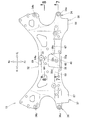
- the vehicle body front structure 10 includes left and right side frames 11, 12 arranged in the longitudinal direction of the vehicle body, and subs attached below the left and right side frames 11, 12.
- the frame 15 includes left and right suspension arms 16 and 17 provided at left and right ends of the subframe 15, and left and right suspensions 21 and 22 connected to the left and right suspension arms 16 and 17.
- the vehicle body front structure 10 further includes a steering gear box 24 attached to the upper portion 15a of the subframe 15 and a torque rod (connecting member) 26 that connects the subframe 15 and the power plant 25.
- a steering wheel 29 is attached to a steering shaft 28 extending from the steering gear box 24.
- the power plant 25 is an engine / transmission unit in which an engine and a transmission are integrally formed and serves as a drive source of the vehicle.
- the power plant 25 is disposed horizontally between the left and right side frames 11 and 12.
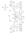
- the subframe 15 is formed into a wall thickness T ⁇ b> 1 by high pressure casting integrally with an aluminum alloy using a core unit 80 (see FIG. 9).
- the subframe 15 includes a main body portion 32 formed in a hollow shape by the core unit 80, a left vehicle body attachment portion 34 and a left suspension support portion 35 provided at the left end portion 32 a of the main body portion 32, and the main body portion 32.
- a right vehicle body attachment portion 36 and a right suspension support portion 37 provided at the right end portion 32 b and a central coupling portion 38 provided at the front center portion of the main body portion 32 are provided.
- the left vehicle body attachment portion 34 includes a left front attachment portion 34a provided at the front portion 32c of the left end portion 32a of the main body portion 32, and a left rear attachment portion 34b provided at the rear portion 32d of the left end portion 32a of the main body portion 32. including.
- the right vehicle body attachment portion 36 includes a right front attachment portion 36 a provided at the front portion 32 e of the right end portion 32 b of the main body portion 32 and a rear portion 32 f of the right end portion 32 b of the main body portion 32. And a right rear mounting portion 36b provided.
- the left front attachment portion 34a and the left rear attachment portion 34b are attached to the left side frame 11 (see FIG. 1) with bolts. Further, the right front attachment portion 36a and the right rear attachment portion 36b are attached to the right side frame 12 (see FIG. 1) with bolts. Thereby, the sub-frame 15 is attached to the left and right side frames 11 and 12.
- the left suspension support portion 35 is connected to the left front connecting portion 81 provided at the front portion 32 c of the left end portion 32 a of the main body portion 32 and the rear portion 32 d of the left end portion 32 a of the main body portion 32. And a left rear connecting portion 82 provided.
- the left front connecting portion 81 is disposed in front of the left front mounting portion 34a by being provided so as to protrude from the front portion 32c to the front of the vehicle.
- the left rear connecting portion 82 is interposed between the left rear mounting portion 34b and the rear portion 32d by being provided on the inner side in the vehicle width direction from the left rear mounting portion 34b (see also FIG. 3).
- a front mounting portion 16 a of the left suspension arm 16 is connected to the left front connection portion 81 via a left front support pin 84.
- the rear attachment portion 16b of the left suspension arm 16 is connected to the left rear connection portion 82 via a left rear support pin.
- a lower end 21 a of the left suspension 21 is connected to the left suspension arm 16, and an upper end 21 b of the left suspension 21 is connected to the left damper housing 13.
- the left damper housing 13 is formed integrally with the left side frame 11. Therefore, the left suspension 21 is supported by the left suspension arm 16. As a result, the left suspension 21 is supported by the left suspension support portion 35 via the left suspension arm 16.
- the right suspension support portion 37 is connected to the right front connection portion 87 provided at the front portion 32 e of the right end portion 32 b of the main body portion 32 and the rear portion 32 f of the right end portion 32 b of the main body portion 32. And a right rear connecting portion 88 provided.
- the right front connecting portion 87 is disposed in front of the vehicle from the right front mounting portion 36a by being provided so as to protrude from the front portion 32e to the front of the vehicle.
- the right rear connecting portion 88 is interposed between the right rear mounting portion 36b and the rear portion 32f by being provided on the inner side in the vehicle width direction from the right rear mounting portion 36b (see also FIG. 3).
- a front mounting portion 17 a of the right suspension arm 17 is connected to the right front connection portion 87 via a right front support pin 91.
- the rear attachment portion 17b of the right suspension arm 17 is connected to the right rear connection portion 88 via a right rear support pin.
- the right suspension arm 17 is a member that is substantially symmetrical with the left suspension arm 16.
- a lower end 22 a of the right suspension 22 is connected to the right suspension arm 17, and an upper end 22 b of the right suspension 22 is connected to the right damper housing 14.
- the right damper housing 14 is formed integrally with the right side frame 11. Therefore, the right suspension 22 is supported by the right suspension arm 17. As a result, the right suspension 22 is supported by the right suspension support portion 37 via the right suspension arm 17.
- a central coupling portion 38 is provided in the vehicle width direction center portion 32 h of the main body portion 32 and in the front half portion (front portion in the vehicle front-rear direction) 32 g.
- the base end portion 26 a of the torque rod 26 is connected to the central connecting portion 38 by a bolt 51 (see FIG. 1) and a nut 52.
- a tip end portion 26 b of the torque rod 26 is connected to the power plant 25 by a bolt 53. Thereby, the power plant 25 is supported by the torque rod 26.
- the main body 32 includes an upper part 41 facing upward, a lower part 42 facing downward, a front wall 43 connecting the front end parts 41a and 42a of the upper part 41 and the lower part 42, and an upper part. 41 and the rear wall 44 which connects each rear-end part 41b of the lower part 42, 42b.
- a hollow portion 45 is formed by an upper portion 41, a lower portion 42, a front wall 43 and a rear wall 44.
- the hollow portion 45 is formed by the core unit 80 (see FIG. 9) when the subframe 15 is cast.
- the upper part 41 and the lower part 42 are provided at a predetermined interval in the vertical direction.
- a central connecting portion 38 is integrally formed at the center of the upper portion 41 in the vehicle width direction and at the front half portion 32g.
- a connecting recess 47 is integrally formed in the center of the lower portion 42 in the vehicle width direction and in a front portion (that is, a portion corresponding to the lower portion 38a of the central connecting portion 38) 42c.
- An upper mounting hole 54 is formed in the upper part 38b of the central coupling part 38, and a lower mounting hole 55 is formed in the lower part 38a (including the front part 42c of the lower part 42) of the central coupling part 38.
- the main body portion 32 includes a partition wall portion 61 provided in the vehicle width direction center portion 32 h.
- the partition wall portion 61 includes a front partition wall 62 provided in front of the center connection portion 38 in the vehicle, a center partition wall 63 provided in the lower portion of the center connection portion 38, and a rear partition wall provided in the rear of the center connection portion 38 ( Partition wall) 64.
- the partition wall 61 will be described in detail later.
- the main body 32 includes left and right upper front horizontal ribs 67 and 68 and an upper rear center horizontal rib 69 which are provided on the inner surface 41 c (see FIG. 4) of the upper portion 41 and reinforce the subframe 15.
- the upper left front horizontal rib 67 extends outward in the vehicle width direction from the left end portion 38c of the central connecting portion 38, and protrudes from the inner surface 41c toward the hollow portion 45 (see FIG. 4).
- the upper right front horizontal rib 68 is a rib symmetrical to the upper left front horizontal rib 67, extends outward in the vehicle width direction from the right end portion 38d of the central coupling portion 38, and protrudes from the inner surface 41c toward the hollow portion 45. ing.
- the upper rear center horizontal rib 69 extends outward in the vehicle width direction from the rear end portion 64a of the rear partition wall 64 in both the left and right directions, and protrudes from the inner surface 41c toward the hollow portion 45 (see FIG. 4). ing.
- the upper portion 41 ie, the subframe 15
- the ribs 67, 68, 69 is reinforced by the ribs 67, 68, 69. .
- the main body 32 includes a lower front center horizontal rib 71 and left and right rear inclined ribs 72 and 73 provided on the inner surface 42d (see FIG. 4) of the lower portion 42 to reinforce the subframe 15.
- the lower front center horizontal rib 71 extends outward in the vehicle width direction from the front partition wall 62 in both the left and right directions, and protrudes from the inner surface 42d toward the hollow portion 45 (see FIG. 4).
- the left rear inclined rib 72 extends from the vicinity of the left side of the rear partition wall 64 so as to spread outward in the vehicle width direction toward the rear of the vehicle, and protrudes toward the hollow portion 45 from the inner surface 42d.
- the right rear inclined rib 73 is symmetrical to the left rear inclined rib 72, extends from the right side of the rear partition wall 64 so as to spread outward in the vehicle width direction toward the rear of the vehicle, and is hollow from the inner surface 42d. It protrudes toward 45.
- the lower front center horizontal rib 71 and the left and right rear inclined ribs 72, 73 are provided on the inner surface 42d of the lower part 42, the lower part 42 (ie, the subframe 15) is reinforced by the ribs 71, 72, 73.
- a partition wall 61 is provided in the vehicle width direction central portion 32 h of the main body 32 (see also FIG. 5).
- the partition wall portion 61 includes a front partition wall 62 provided in front of the center connection portion 38 in the vehicle, a center partition wall 63 provided in the lower portion of the center connection portion 38, and a rear partition wall 64 provided in the rear of the center connection portion 38 in the vehicle. It consists of and.
- the front partition wall 62 is provided in the vehicle width direction center portion 32 h of the main body portion 32 in front of the center connection portion 38 and below the center connection portion 38.
- the front partition wall 62 is connected to the front portion 41d of the upper portion 41, the front wall 43, the front portion 42e of the lower portion 42, and the front portion 47a of the connecting recess 47, and extends in the vehicle front-rear direction.
- the central partition wall 63 is provided in the vehicle width direction central portion 32 h of the main body portion 32 at the lower portion 38 a of the central coupling portion 38 and below the central coupling portion 38. .
- the central partition wall 63 is connected to the lower portion 38 a of the central connection portion 38, the rear portion 47 b of the connection recess 47 and the central portion 42 f of the lower portion 42, and extends in the vehicle front-rear direction on the extension line of the front partition wall 62.
- the rear partition wall 64 is provided on the vehicle rear side of the central connecting portion 38 in the vehicle width direction central portion 32 h of the main body portion 32.
- the rear partition wall 64 is connected to the rear portion 41 e of the upper portion 41, the rear portion 38 e of the central connection portion 38, the rear portion 42 g of the lower portion 42, and the rear wall 44, and extends in the vehicle front-rear direction on the extension line of the central partition wall 63.
- the front end portion 64 b of the rear partition wall 64 is integrally connected to the rear end portion 63 a of the central partition wall 63. Therefore, the upper part 41, the lower part 42, the front wall 43 and the rear wall 44 of the main body part 32 are integrally connected by the partition wall part 61 (that is, the front partition wall 62, the central partition wall 63 and the rear partition wall 64).
- the subframe 15 is formed in a state where the core unit 80 (see FIG. 9) is disposed in the casting mold during casting. As shown in FIG. 9, the core unit 80 is divided into a left core 81 and a right core 82 in a state corresponding to the vehicle width direction central portion 32h of the subframe 15 (see FIG. 3). It is made of sand.
- the partition wall portion 61 can be easily formed in the subframe 15 with a simple configuration in which the core unit 80 is divided into the left core 81 and the right core 82 and the gap S1 is secured. . Thereby, the partition part 61 can be formed in the state which suppressed the cost of the sub-frame 15 (refer FIG. 3).
- the left core 81 is provided with a left half portion of an upper left front lateral groove 85 and an upper rear lateral groove 86 in an upper portion 84.
- the left half of the upper left front horizontal groove 85 and the upper rear horizontal groove 86 the left half of the upper left front horizontal rib 67 and the upper rear central horizontal rib 69 is formed in the left half of the subframe 15 (upper part 41) shown in FIG.
- the left core 81 is provided with a left half portion of the lower rear center lateral groove and a left rear inclined groove in the lower portion.
- the left half of the lower front center horizontal rib 71 and the left rear inclined rib 72 are formed in the left half of the subframe 15 (lower part 42) shown in FIG.
- the left core 81 is provided with a left half portion of an upper left front lateral groove 85 and an upper rear lateral groove 86 in an upper portion 84.
- the left half of the upper left front horizontal rib 67 and the upper rear central horizontal rib 69 is formed in the left half of the
- the right core 82 is a member substantially symmetrical to the left core 81, and the upper half 88 is provided with the right half of the upper right front lateral groove 89 and the upper rear lateral groove 86.
- the right half of the upper right front lateral groove 89 and the upper rear lateral groove 86 the right half of the upper right front lateral rib 68 and the upper rear center lateral rib 69 are formed in the right half of the subframe 15 (upper part 41) shown in FIG.
- the right core 82 is provided with a right half portion of the lower rear center lateral groove and a right rear inclined groove in the lower portion.
- the right half of the lower front center horizontal rib 71 and the right rear inclined rib 73 are formed in the right half of the subframe 15 (lower part 42) shown in FIG.
- a front partition 62 is provided below the center connecting portion 38 in front of the vehicle
- a center partition 63 is provided below the central connecting portion 38
- a rear partition 64 is provided behind the center connecting portion 38 in the vehicle. It has been. That is, the partition wall portion 61 is provided in the vehicle width direction center portion 32 h of the main body portion 32. Further, the upper portion 41, the lower portion 42, the front wall 43 and the rear wall 44 of the main body portion 32 are integrally connected by a partition wall portion 61.
- the rigidity and strength of the subframe 15 (particularly, the lower portion 32i of the central coupling portion 38 and the rear portion 32j behind the vehicle of the central coupling portion 38) can be ensured.
- the vehicle front-rear direction load F1 input to the central coupling portion 38 via the torque rod 26 can be supported by the lower portion 32i and the rear portion 32j.
- the vertical load F2 input to the central coupling portion 38 via the torque rod 26 can be supported by the lower portion 32i and the rear portion 32j.
- loads in other directions can be supported by the lower portion 32i and the rear portion 32j, not limited to the loads F1 and F2 that are input to the central coupling portion 38 via the torque rod 26.
- the loads F1 and F2 and loads in other directions can be supported by the lower part 32i and the rear part 32j.
- the vibration of the power plant 25 (see FIG. 2) is transmitted to the subframe 15 via the torque rod 26, the transmitted vibration can be suitably supported by the subframe 15.
- the rigidity and strength of the subframe 15 (particularly, the lower portion 32i and the rear portion 32j) can be increased by simply connecting the upper portion 41, the lower portion 42, the front wall 43 and the rear wall 44 of the main body portion 32 with the partition wall portion 61. It can be secured. Thereby, the weight reduction of the sub-frame 15 can be achieved compared with the case where the thickness dimension T1 of the sub-frame 15 (especially the thickness dimension of the whole circumference
- the sub-frame of the vehicle according to the present invention is not limited to the above-described embodiment, and can be changed or improved as appropriate.
- the subframe 15 made of aluminum alloy has been described.
- the present invention is not limited to this, and the present invention can be applied to other metals.
- the present invention is not limited to this, and the present invention can be applied to other castings.
- the central connecting portion (connecting portion) 38 is provided in the front center portion of the main body portion 32 and the partition wall portion 61 is provided in the vehicle width direction central portion 32h of the main body portion 32 has been described.
- the central coupling portion 38 and the partition wall portion 61 may be provided in other parts of the main body portion 32.
- subframe left and right suspension arms, left and right suspension, power plant, torque rod, main body, left and right suspension support, central connection, upper, lower, partition, rear partition, etc.
- the shape and configuration are not limited to those illustrated, and can be changed as appropriate.
- the present invention is suitable for application to an automobile provided with a subframe that is provided below the vehicle body and supports the left suspension at the left end and the right suspension at the right end.
- SYMBOLS 10 Vehicle body front part structure, 15 ... Sub-frame (vehicle sub-frame), 16, 17 ... Left and right suspension arm (suspension arm), 21, 22 ... Left and right suspension (suspension), 25 ... Power plant, 26 ... Torque rod (connecting member), 32 ... body part, 32a ... left end part of body part, 32b ... right end part of body part, 32g ... front half part (front part in vehicle longitudinal direction), 32h ... vehicle width direction center of body part 35, 37 ... left and right suspension support parts, 38 ... central connection part (connection part), 41 ... upper part, 42 ... lower part, 61 ... partition wall part, 64 ... rear partition wall (partition wall), 80 ... core unit (medium Child).
- connection part connection part
Abstract
Description
パワープラントは、一例として、エンジンとトランスミッションとが一体に形成されたエンジン/トランスミッションユニットである。 2. Description of the Related Art Some vehicles are known in which a vehicle body frame is provided with a cast sub-frame, and a torque rod is connected to the center of the sub-frame in the vehicle width direction (hereinafter referred to as “connecting portion”). By connecting the torque rod to the subframe, the power plant of the vehicle is supported by the subframe via the torque rod.
As an example, the power plant is an engine / transmission unit in which an engine and a transmission are integrally formed.
このため、サブフレームの肉厚寸法(特に、車幅方向中央の肉厚寸法)を大きくして連結部の剛性・強度を確保する必要があり、そのことがサブフレームの軽量化を図る妨げになっていた。 However, in the subframe of Patent Document 1, a relatively large load is input from the torque rod to the center of the subframe in the vehicle width direction (that is, the connecting portion) when the power plant is supported by the connecting portion via the torque rod. To do.
For this reason, it is necessary to increase the thickness of the subframe (particularly the thickness in the center in the vehicle width direction) to ensure the rigidity and strength of the connecting portion, which hinders the weight reduction of the subframe. It was.
隔壁を上部および下部に連結させることにより、連結部の車両後方において上部および下部を隔壁で一体に連結することができ、サブフレーム(特に、連結部の後方部位)の剛性・強度を確保できる。
これにより、連結部材を経て連結部に入力される車両前後方向や上下方向の荷重を後方部位で支えることができる。 In the invention which concerns on Claim 1, the connection part was provided in the front part of the vehicle front-back direction among the main-body parts. Further, a partition wall was provided at the rear of the connecting portion, and the partition wall was connected to the upper part and the lower part.
By connecting the partition walls to the upper portion and the lower portion, the upper portion and the lower portion can be integrally connected by the partition walls at the rear of the connecting portion, and the rigidity and strength of the subframe (particularly, the rear portion of the connecting portion) can be ensured.
Thereby, the vehicle front-back direction and the load of an up-down direction input into a connection part via a connection member can be supported by a back site | part.
ここで、本体部の中空部を形成する中子を、本体部の車両幅方向中央部に相当する部位で2分割することにより、分割された中子間に溶湯を流して隔壁を形成することができる。
これにより、中子を2分割するだけで、分割された中子間に隔壁を簡単に形成することができる。 In the invention which concerns on Claim 2, a partition was provided in the vehicle width direction center part of the main-body part.
Here, by dividing the core forming the hollow portion of the main body portion into two at the portion corresponding to the center portion in the vehicle width direction of the main body portion, the partition wall is formed by flowing molten metal between the divided cores. Can do.
Thereby, a partition can be easily formed between the divided cores only by dividing the core into two.
図1、図2に示すように、車体前部構造体10は、車体前後方向に向けて配置された左右のサイドフレーム11,12と、左右のサイドフレーム11,12の下方に取り付けられたサブフレーム15と、サブフレーム15の左右の端部に設けられた左右のサスペンションアーム16,17と、左右のサスペンションアーム16,17に連結された左右のサスペンション21,22とを備えている。 The
As shown in FIGS. 1 and 2, the vehicle
ステアリングギヤボックス24から延出されたステアリングシャフト28にステアリングホイール29が取り付けられている。
パワープラント25は、一例として、エンジンとトランスミッションとが一体に形成され、車両の駆動源となるエンジン/トランスミッションユニットである。このパワープラント25は、左右のサイドフレーム11,12間に横向きに配置されている。 The vehicle
A
As an example, the
このサブフレーム15は、中子ユニット80で中空状に形成された本体部32と、本体部32の左端部32aに設けられた左車体取付部34および左サスペンション支持部35と、本体部32の右端部32bに設けられた右車体取付部36および右サスペンション支持部37と、本体部32の前中央部に設けられた中央連結部38とを備えている。 As shown in FIGS. 3 and 4, the
The
右車体取付部36は、左車体取付部34と同様に、本体部32の右端部32bのうち前部32eに設けられた右前取付部36aと、本体部32の右端部32bのうち後部32fに設けられた右後取付部36bとを含む。 The left vehicle
Similarly to the left vehicle
これにより、サブフレーム15が左右のサイドフレーム11,12に取り付けられる。 The left
Thereby, the
左後連結部82は、左後取付部34b(図3も参照)より車幅方向内側に設けられることにより、左後取付部34bおよび後部32d間に介在されている。
左前連結部81に左サスペンションアーム16の前取付部16aが左前支持ピン84を介して連結されている。また、左後連結部82に左サスペンションアーム16の後取付部16bが左後支持ピンを介して連結されている。 The left
The left rear connecting
A
よって、左サスペンション21が左サスペンションアーム16に支持される。これにより、左サスペンション21が左サスペンションアーム16を介して左サスペンション支持部35に支持される。 A
Therefore, the
右後連結部88は、右後取付部36b(図3も参照)より車幅方向内側に設けられることにより、右後取付部36bおよび後部32f間に介在されている。
右前連結部87に右サスペンションアーム17の前取付部17aが右前支持ピン91を介して連結されている。また、右後連結部88に右サスペンションアーム17の後取付部17bが右後支持ピンを介して連結されている。 The right
The right
A front mounting
右サスペンションアーム17に右サスペンション22の下端部22aが連結され、右ダンパハウジング14に右サスペンション22の上端部22bが連結されている。右ダンパハウジング14は右サイドフレーム11に一体に形成されている。
よって、右サスペンション22が右サスペンションアーム17に支持される。これにより、右サスペンション22が右サスペンションアーム17を介して右サスペンション支持部37に支持される。 The
A
Therefore, the
中央連結部38にトルクロッド26の基端部26aがボルト51(図1参照)、ナット52で連結されている。トルクロッド26の先端部26bがパワープラント25にボルト53で連結されている。これにより、パワープラント25がトルクロッド26で支持されている。 As shown in FIGS. 2 and 3, a
The
中空部45は、サブフレーム15を鋳造する際に中子ユニット80(図9参照)で形成される。
さらに、上部41および下部42は、上下方向に所定間隔をおいて設けられている。 As shown in FIGS. 3 and 4, the
The
Furthermore, the
下部42の車幅方向中央で、かつ、前部(すなわち、中央連結部38の下部38aに相当する部位)42cに連結凹部47が一体に形成されている。
中央連結部38の上部38bに上取付孔54が形成され、中央連結部38の下部38a(下部42の前部42cを含む)に下取付孔55が形成されている。上取付孔54および下取付孔55にボルト51が差し込まれることにより、ボルト51にトルクロッド26が連結される。 A central connecting
A connecting
An upper mounting
隔壁部61については後で詳しく説明する。 As shown in FIGS. 5 and 6, the
The
左上前横リブ67は、中央連結部38の左端部38cから車幅方向外方に延出され、内面41cから中空部45(図4参照)に向けて突出されている。
右上前横リブ68は、左上前横リブ67と左右対称のリブであり、中央連結部38の右端部38dから車幅方向外方に延出され、内面41cから中空部45に向けて突出されている。 The
The upper left front
The upper right front
上部41の内面41cに左右の上前横リブ67,68および上後中央横リブ69が設けられることにより、各リブ67,68,69で上部41(すなわち、サブフレーム15)が補強されている。 The upper rear center
By providing left and right upper front
下前中央横リブ71は、前隔壁62から左側および右側の両方向へ向けて車幅方向外方に延出し、内面42dから中空部45(図4参照)に向けて突出されている。
左後傾斜リブ72は、後隔壁64の左側近傍から車両後方に向けて車幅方向外方に広がるように延出され、内面42dから中空部45に向けて突出されている。 Further, the
The lower front center
The left rear
下部42の内面42dに下前中央横リブ71および左右の後傾斜リブ72,73が設けられることにより、各リブ71,72,73で下部42(すなわち、サブフレーム15)が補強されている。 The right rear
By providing the lower front center
図4に戻って、本体部32の車幅方向中央部32hに隔壁部61が設けられている(図5も参照)。隔壁部61は、中央連結部38の車両前方に設けられた前隔壁62と、中央連結部38の下部に設けられた中央隔壁63と、中央連結部38の車両後方に設けられた後隔壁64とで構成されている。 Here, the
Returning to FIG. 4, a
この前隔壁62は、上部41の前部41d、前壁43、下部42の前部42eおよび連結凹部47の前部47aに連結され、車両前後方向に延出されている。 The
The
この中央隔壁63は、中央連結部38の下部38a、連結凹部47の後部47bおよび下部42の中央部42fに連結され、前隔壁62の延長線上において車両前後方向に延出されている。 As shown in FIGS. 4 and 7, the
The
この後隔壁64は、上部41の後部41e、中央連結部38の後部38e、下部42の後部42gおよび後壁44に連結され、中央隔壁63の延長線上において車両前後方向に延出されている。
後隔壁64の前端部64bは中央隔壁63の後端部63aに一体に連結されている。
よって、本体部32の上部41、下部42、前壁43および後壁44が隔壁部61(すなわち、前隔壁62、中央隔壁63および後隔壁64)で一体に連結されている。 As shown in FIGS. 4 and 8, the
The
The
Therefore, the
図9に示すように、中子ユニット80は、サブフレーム15(図3参照)の車両幅方向中央部32hに相当する部位で左中子81および右中子82に2分割した状態に中子用の砂で形成されている。 Here, the
As shown in FIG. 9, the
よって、サブフレーム15(図3参照)を鋳造型で鋳造成形する際に、左中子81および右中子82間の間隔S1にアルミニウム合金の溶湯が充填される。溶湯が間隔S1に充填されることにより、サブフレーム15に隔壁部61(前隔壁62、中央隔壁63および後隔壁64)(図4参照)が形成される。 In a state where the
Therefore, when the subframe 15 (see FIG. 3) is cast with a casting mold, the aluminum alloy melt is filled in the space S1 between the
さらに、左中子81は、下部に下後中央横溝の左半部および左後傾斜溝が設けられている。下後中央横溝の左半部および左後傾斜溝で、図6に示すサブフレーム15(下部42)の左半部に下前中央横リブ71の左半部および左後傾斜リブ72が形成される。 Further, the
Further, the
さらに、右中子82は、下部に下後中央横溝の右半部および右後傾斜溝が設けられている。下後中央横溝の右半部および右後傾斜溝で、図6に示すサブフレーム15(下部42)の右半部に下前中央横リブ71の右半部および右後傾斜リブ73が形成される。 The
Further, the
図10に示すように、中央連結部38の車両前下方に前隔壁62が設けられ、中央連結部38の下方に中央隔壁63が設けられ、中央連結部38の車両後方に後隔壁64が設けられている。すなわち、本体部32の車幅方向中央部32hに隔壁部61が設けられている。
さらに、本体部32の上部41、下部42、前壁43および後壁44が隔壁部61で一体に連結されている。 Next, an example of supporting the load input to the
As shown in FIG. 10, a
Further, the
これにより、トルクロッド26を経て中央連結部38に入力される車両前後方向の荷重F1を下方部位32iや後方部位32jで支えることができる。
さらに、トルクロッド26を経て中央連結部38に入力される上下方向の荷重F2を下方部位32iや後方部位32jで支えることができる。
加えて、トルクロッド26を経て中央連結部38に入力される荷重F1,F2に限らないで、その他の方向の荷重も下方部位32iや後方部位32jで支えることができる。 Therefore, the rigidity and strength of the subframe 15 (particularly, the
Thus, the vehicle front-rear direction load F1 input to the
Furthermore, the vertical load F2 input to the
In addition, loads in other directions can be supported by the
これにより、サブフレーム15の肉厚寸法T1(特に、連結部の周囲全域の肉厚寸法)を大きくする場合と比べて、サブフレーム15の軽量化を図ることができる。 Further, the rigidity and strength of the subframe 15 (particularly, the
Thereby, the weight reduction of the
例えば、前記実施例では、アルミニウム合金製のサブフレーム15について説明したが、これに限らないで、本発明は他の金属に適用することも可能である。 In addition, the sub-frame of the vehicle according to the present invention is not limited to the above-described embodiment, and can be changed or improved as appropriate.
For example, in the above embodiment, the
Claims (2)
- 中子を用いて一体に鋳造形成され、
前記中子で中空状に形成されることにより、上下方向に所定間隔をおいて設けられた上部および下部を有する本体部と、
該本体部の左右端部に設けられ、サスペンションを支持するサスペンションアームが連結される左右のサスペンション支持部と、
前記本体部に設けられ、車両の駆動源となるパワープラントを支持する連結部材が連結される連結部とを備えた車両のサブフレームであって、
前記連結部は、
前記本体部の車両前後方向の前部に設けられ、
前記本体部は、
前記連結部の車両後方において前記上部および前記下部に連結され、車両前後方向に延びる隔壁を含むことを特徴とする車両のサブフレーム。 It is integrally cast using a core,
By forming a hollow shape in the core, a main body having an upper part and a lower part provided at a predetermined interval in the vertical direction,
Left and right suspension support portions provided at left and right end portions of the main body portion to which suspension arms for supporting the suspension are coupled;
A vehicle sub-frame provided with a connecting portion provided to the main body portion and connected to a connecting member that supports a power plant serving as a driving source of the vehicle;
The connecting portion is
Provided at the front of the main body in the longitudinal direction of the vehicle,
The main body is
A vehicle sub-frame comprising a partition wall connected to the upper part and the lower part at a vehicle rear side of the connecting part and extending in a vehicle front-rear direction. - 前記隔壁は、前記本体部の車両幅方向中央部に設けられている、請求項1記載の車両のサブフレーム。 The vehicle subframe according to claim 1, wherein the partition wall is provided at a central portion of the main body portion in the vehicle width direction.
Priority Applications (6)
| Application Number | Priority Date | Filing Date | Title |
|---|---|---|---|
| CN201480030155.8A CN105246767B (en) | 2013-04-26 | 2014-04-25 | The subframe of vehicle |
| JP2015513854A JP6148333B2 (en) | 2013-04-26 | 2014-04-25 | Vehicle subframe |
| BR112015026926A BR112015026926A8 (en) | 2013-04-26 | 2014-04-25 | vehicular substructure |
| US14/786,426 US9434417B2 (en) | 2013-04-26 | 2014-04-25 | Vehicle subframe |
| MX2015014881A MX365995B (en) | 2013-04-26 | 2014-04-25 | Vehicle subframe. |
| EP14788182.5A EP2990305B1 (en) | 2013-04-26 | 2014-04-25 | Vehicle subframe |
Applications Claiming Priority (2)
| Application Number | Priority Date | Filing Date | Title |
|---|---|---|---|
| JP2013093972 | 2013-04-26 | ||
| JP2013-093972 | 2013-04-26 |
Publications (1)
| Publication Number | Publication Date |
|---|---|
| WO2014175431A1 true WO2014175431A1 (en) | 2014-10-30 |
Family
ID=51791996
Family Applications (1)
| Application Number | Title | Priority Date | Filing Date |
|---|---|---|---|
| PCT/JP2014/061719 WO2014175431A1 (en) | 2013-04-26 | 2014-04-25 | Vehicle subframe |
Country Status (7)
| Country | Link |
|---|---|
| US (1) | US9434417B2 (en) |
| EP (1) | EP2990305B1 (en) |
| JP (1) | JP6148333B2 (en) |
| CN (1) | CN105246767B (en) |
| BR (1) | BR112015026926A8 (en) |
| MX (1) | MX365995B (en) |
| WO (1) | WO2014175431A1 (en) |
Cited By (1)
| Publication number | Priority date | Publication date | Assignee | Title |
|---|---|---|---|---|
| US20150075896A1 (en) * | 2013-09-13 | 2015-03-19 | Honda Motor Co., Ltd. | Sub-frame for vehicle |
Families Citing this family (8)
| Publication number | Priority date | Publication date | Assignee | Title |
|---|---|---|---|---|
| WO2014175416A1 (en) * | 2013-04-26 | 2014-10-30 | 本田技研工業株式会社 | Vehicle subframe |
| DE102013108695B4 (en) * | 2013-08-12 | 2022-06-30 | Kirchhoff Automotive Deutschland Gmbh | Subframe for a motor vehicle axle |
| JP6137144B2 (en) * | 2014-11-27 | 2017-05-31 | トヨタ自動車株式会社 | Suspension member |
| CN107971703A (en) * | 2017-11-24 | 2018-05-01 | 芜湖禾田汽车工业有限公司 | The processing method of tower structure Welded subframe |
| JP7056115B2 (en) * | 2017-12-08 | 2022-04-19 | いすゞ自動車株式会社 | Suspension device |
| JP7272928B2 (en) * | 2019-10-18 | 2023-05-12 | トヨタ自動車株式会社 | Vehicle support member |
| JP2022152263A (en) * | 2021-03-29 | 2022-10-12 | 本田技研工業株式会社 | Sub frame |
| JP2022152260A (en) * | 2021-03-29 | 2022-10-12 | 本田技研工業株式会社 | Sub frame |
Citations (4)
| Publication number | Priority date | Publication date | Assignee | Title |
|---|---|---|---|---|
| JP2007253642A (en) * | 2006-03-20 | 2007-10-04 | Daihatsu Motor Co Ltd | Lower structure of automobile |
| JP2012061921A (en) * | 2010-09-15 | 2012-03-29 | Suzuki Motor Corp | Torque rod mounting structure of vehicle |
| JP2012091693A (en) | 2010-10-27 | 2012-05-17 | Daihatsu Motor Co Ltd | Suspension member |
| US8302979B2 (en) * | 2007-11-08 | 2012-11-06 | Ksm Castings Gmbh | Front-axle bracket for motor vehicles |
Family Cites Families (16)
| Publication number | Priority date | Publication date | Assignee | Title |
|---|---|---|---|---|
| JP4138074B2 (en) * | 1998-05-11 | 2008-08-20 | 本田技研工業株式会社 | Vehicle body structure |
| JP2004051066A (en) * | 2002-07-24 | 2004-02-19 | Kobe Steel Ltd | Aluminum alloy hollow structural angle for sub-frame and sub-frame |
| DE502006008675D1 (en) * | 2005-09-13 | 2011-02-17 | Ksm Castings Gmbh | FRONT AXLE CARRIER, ESPECIALLY FOR MOTOR VEHICLES |
| JP4901688B2 (en) * | 2007-10-17 | 2012-03-21 | 本田技研工業株式会社 | Body front structure |
| DE102009043474A1 (en) * | 2008-10-30 | 2010-05-12 | Ksm Castings Gmbh | Front axle for a motor vehicle and method for its production |
| KR101034019B1 (en) * | 2008-11-20 | 2011-05-11 | 현대자동차주식회사 | Dynamic damping apparatus |
| CN102470894B (en) * | 2009-07-06 | 2015-03-11 | Ksm铸造集团有限公司 | Axle support for motor vehicles and method for manufacturing same |
| CN201472467U (en) * | 2009-09-17 | 2010-05-19 | 上海汽车集团股份有限公司 | Sub-frame and strengthening support structure therein |
| DE102011115387A1 (en) * | 2010-11-02 | 2012-05-03 | Ksm Castings Gmbh | Axle carrier, in particular front axle carrier for motor vehicles |
| CN202071883U (en) * | 2011-04-19 | 2011-12-14 | 宁波建新底盘系统有限公司 | Assembling structure of front auxiliary automobile frame |
| JP5910936B2 (en) * | 2012-03-14 | 2016-04-27 | スズキ株式会社 | Vehicle light alloy suspension member |
| JP5879438B2 (en) * | 2012-07-27 | 2016-03-08 | 本田技研工業株式会社 | Subframe for vehicle |
| WO2014175416A1 (en) * | 2013-04-26 | 2014-10-30 | 本田技研工業株式会社 | Vehicle subframe |
| JP5953582B2 (en) * | 2013-09-13 | 2016-07-20 | 本田技研工業株式会社 | Vehicle subframe |
| JP6021769B2 (en) * | 2013-09-13 | 2016-11-09 | 本田技研工業株式会社 | Subframe for vehicle and method for manufacturing the same |
| US9394002B2 (en) * | 2014-03-20 | 2016-07-19 | Ford Global Technologies, Llc | Extruded metal sub-frame for a vehicle |
-
2014
- 2014-04-25 EP EP14788182.5A patent/EP2990305B1/en not_active Not-in-force
- 2014-04-25 US US14/786,426 patent/US9434417B2/en active Active
- 2014-04-25 BR BR112015026926A patent/BR112015026926A8/en active Search and Examination
- 2014-04-25 WO PCT/JP2014/061719 patent/WO2014175431A1/en active Application Filing
- 2014-04-25 CN CN201480030155.8A patent/CN105246767B/en active Active
- 2014-04-25 MX MX2015014881A patent/MX365995B/en active IP Right Grant
- 2014-04-25 JP JP2015513854A patent/JP6148333B2/en active Active
Patent Citations (4)
| Publication number | Priority date | Publication date | Assignee | Title |
|---|---|---|---|---|
| JP2007253642A (en) * | 2006-03-20 | 2007-10-04 | Daihatsu Motor Co Ltd | Lower structure of automobile |
| US8302979B2 (en) * | 2007-11-08 | 2012-11-06 | Ksm Castings Gmbh | Front-axle bracket for motor vehicles |
| JP2012061921A (en) * | 2010-09-15 | 2012-03-29 | Suzuki Motor Corp | Torque rod mounting structure of vehicle |
| JP2012091693A (en) | 2010-10-27 | 2012-05-17 | Daihatsu Motor Co Ltd | Suspension member |
Cited By (2)
| Publication number | Priority date | Publication date | Assignee | Title |
|---|---|---|---|---|
| US20150075896A1 (en) * | 2013-09-13 | 2015-03-19 | Honda Motor Co., Ltd. | Sub-frame for vehicle |
| US9150250B2 (en) * | 2013-09-13 | 2015-10-06 | Honda Motor Co., Ltd. | Sub-frame for vehicle |
Also Published As
| Publication number | Publication date |
|---|---|
| MX2015014881A (en) | 2016-06-21 |
| MX365995B (en) | 2019-06-20 |
| BR112015026926A2 (en) | 2017-07-25 |
| US9434417B2 (en) | 2016-09-06 |
| BR112015026926A8 (en) | 2019-12-31 |
| US20160090125A1 (en) | 2016-03-31 |
| EP2990305B1 (en) | 2018-06-13 |
| EP2990305A1 (en) | 2016-03-02 |
| CN105246767B (en) | 2017-08-08 |
| JPWO2014175431A1 (en) | 2017-02-23 |
| CN105246767A (en) | 2016-01-13 |
| JP6148333B2 (en) | 2017-06-14 |
| EP2990305A4 (en) | 2017-02-15 |
Similar Documents
| Publication | Publication Date | Title |
|---|---|---|
| JP6148333B2 (en) | Vehicle subframe | |
| JP5953582B2 (en) | Vehicle subframe | |
| JP6025972B2 (en) | Vehicle subframe | |
| JP4516497B2 (en) | Motorcycle body frame | |
| JP6021769B2 (en) | Subframe for vehicle and method for manufacturing the same | |
| JP4676257B2 (en) | Sub-frame | |
| JP2007302147A (en) | Sub-frame structure for vehicle | |
| JP2012136195A (en) | Suspension member | |
| JP4418280B2 (en) | Subframe for vehicle | |
| US20190061820A1 (en) | Auxiliary frame for motor vehicles | |
| JP6204089B2 (en) | Motorcycle body frame | |
| JP2010069965A (en) | Front suspension member | |
| JP2011168087A (en) | Torque rod for automobile | |
| US20190337567A1 (en) | Assembly of a vehicle cradle on a body including a casting | |
| JP5157470B2 (en) | Rear swing arm for motorcycle and method for manufacturing the same | |
| JP2015030330A (en) | Vehicle body frame of saddle-riding type vehicle | |
| JP5230551B2 (en) | Front subframe structure for vehicles | |
| JP5911174B2 (en) | Subframe for vehicle | |
| JP2006076552A (en) | Frame connection structure of vehicle | |
| JP2017065336A (en) | Swing arm | |
| JP4486396B2 (en) | Subframe for vehicle | |
| JP5231877B2 (en) | Support structure for vehicle power source | |
| JP2016150626A (en) | Supporting structure of axle | |
| JP2008222076A (en) | Motorcycle | |
| JPWO2020065900A1 (en) | Subframe structure |
Legal Events
| Date | Code | Title | Description |
|---|---|---|---|
| 121 | Ep: the epo has been informed by wipo that ep was designated in this application |
Ref document number: 14788182 Country of ref document: EP Kind code of ref document: A1 |
|
| WWE | Wipo information: entry into national phase |
Ref document number: 14786426 Country of ref document: US |
|
| WWE | Wipo information: entry into national phase |
Ref document number: MX/A/2015/014881 Country of ref document: MX |
|
| NENP | Non-entry into the national phase |
Ref country code: DE |
|
| WWE | Wipo information: entry into national phase |
Ref document number: IDP00201506954 Country of ref document: ID |
|
| WWE | Wipo information: entry into national phase |
Ref document number: 2014788182 Country of ref document: EP |
|
| REG | Reference to national code |
Ref country code: BR Ref legal event code: B01A Ref document number: 112015026926 Country of ref document: BR |
|
| ENP | Entry into the national phase |
Ref document number: 2015513854 Country of ref document: JP Kind code of ref document: A |
|
| ENP | Entry into the national phase |
Ref document number: 112015026926 Country of ref document: BR Kind code of ref document: A2 Effective date: 20151023 |