WO2014175402A1 - 複層ガラスおよびその製造方法 - Google Patents
複層ガラスおよびその製造方法 Download PDFInfo
- Publication number
- WO2014175402A1 WO2014175402A1 PCT/JP2014/061630 JP2014061630W WO2014175402A1 WO 2014175402 A1 WO2014175402 A1 WO 2014175402A1 JP 2014061630 W JP2014061630 W JP 2014061630W WO 2014175402 A1 WO2014175402 A1 WO 2014175402A1
- Authority
- WO
- WIPO (PCT)
- Prior art keywords
- glass
- bonding layer
- metal member
- island
- glass substrate
- Prior art date
- Legal status (The legal status is an assumption and is not a legal conclusion. Google has not performed a legal analysis and makes no representation as to the accuracy of the status listed.)
- Ceased
Links
- SNJSKHUOEZOUSC-UHFFFAOYSA-N CCC(CC(C)(C)CCCN)I Chemical compound CCC(CC(C)(C)CCCN)I SNJSKHUOEZOUSC-UHFFFAOYSA-N 0.000 description 1
Images







Classifications
-
- E—FIXED CONSTRUCTIONS
- E06—DOORS, WINDOWS, SHUTTERS, OR ROLLER BLINDS IN GENERAL; LADDERS
- E06B—FIXED OR MOVABLE CLOSURES FOR OPENINGS IN BUILDINGS, VEHICLES, FENCES OR LIKE ENCLOSURES IN GENERAL, e.g. DOORS, WINDOWS, BLINDS, GATES
- E06B3/00—Window sashes, door leaves, or like elements for closing wall or like openings; Layout of fixed or moving closures, e.g. windows in wall or like openings; Features of rigidly-mounted outer frames relating to the mounting of wing frames
- E06B3/66—Units comprising two or more parallel glass or like panes permanently secured together
- E06B3/663—Elements for spacing panes
- E06B3/66309—Section members positioned at the edges of the glazing unit
- E06B3/66371—Section members positioned at the edges of the glazing unit positioned entirely outside the gap between the panes
-
- E—FIXED CONSTRUCTIONS
- E06—DOORS, WINDOWS, SHUTTERS, OR ROLLER BLINDS IN GENERAL; LADDERS
- E06B—FIXED OR MOVABLE CLOSURES FOR OPENINGS IN BUILDINGS, VEHICLES, FENCES OR LIKE ENCLOSURES IN GENERAL, e.g. DOORS, WINDOWS, BLINDS, GATES
- E06B3/00—Window sashes, door leaves, or like elements for closing wall or like openings; Layout of fixed or moving closures, e.g. windows in wall or like openings; Features of rigidly-mounted outer frames relating to the mounting of wing frames
- E06B3/66—Units comprising two or more parallel glass or like panes permanently secured together
- E06B3/6612—Evacuated glazing units
-
- E—FIXED CONSTRUCTIONS
- E06—DOORS, WINDOWS, SHUTTERS, OR ROLLER BLINDS IN GENERAL; LADDERS
- E06B—FIXED OR MOVABLE CLOSURES FOR OPENINGS IN BUILDINGS, VEHICLES, FENCES OR LIKE ENCLOSURES IN GENERAL, e.g. DOORS, WINDOWS, BLINDS, GATES
- E06B3/00—Window sashes, door leaves, or like elements for closing wall or like openings; Layout of fixed or moving closures, e.g. windows in wall or like openings; Features of rigidly-mounted outer frames relating to the mounting of wing frames
- E06B3/66—Units comprising two or more parallel glass or like panes permanently secured together
- E06B3/6617—Units comprising two or more parallel glass or like panes permanently secured together one of the panes being larger than another
-
- E—FIXED CONSTRUCTIONS
- E06—DOORS, WINDOWS, SHUTTERS, OR ROLLER BLINDS IN GENERAL; LADDERS
- E06B—FIXED OR MOVABLE CLOSURES FOR OPENINGS IN BUILDINGS, VEHICLES, FENCES OR LIKE ENCLOSURES IN GENERAL, e.g. DOORS, WINDOWS, BLINDS, GATES
- E06B3/00—Window sashes, door leaves, or like elements for closing wall or like openings; Layout of fixed or moving closures, e.g. windows in wall or like openings; Features of rigidly-mounted outer frames relating to the mounting of wing frames
- E06B3/66—Units comprising two or more parallel glass or like panes permanently secured together
- E06B3/663—Elements for spacing panes
- E06B3/66304—Discrete spacing elements, e.g. for evacuated glazing units
-
- E—FIXED CONSTRUCTIONS
- E06—DOORS, WINDOWS, SHUTTERS, OR ROLLER BLINDS IN GENERAL; LADDERS
- E06B—FIXED OR MOVABLE CLOSURES FOR OPENINGS IN BUILDINGS, VEHICLES, FENCES OR LIKE ENCLOSURES IN GENERAL, e.g. DOORS, WINDOWS, BLINDS, GATES
- E06B3/00—Window sashes, door leaves, or like elements for closing wall or like openings; Layout of fixed or moving closures, e.g. windows in wall or like openings; Features of rigidly-mounted outer frames relating to the mounting of wing frames
- E06B3/66—Units comprising two or more parallel glass or like panes permanently secured together
- E06B3/663—Elements for spacing panes
- E06B3/66309—Section members positioned at the edges of the glazing unit
- E06B3/66342—Section members positioned at the edges of the glazing unit characterised by their sealed connection to the panes
- E06B3/66357—Soldered connections or the like
-
- Y—GENERAL TAGGING OF NEW TECHNOLOGICAL DEVELOPMENTS; GENERAL TAGGING OF CROSS-SECTIONAL TECHNOLOGIES SPANNING OVER SEVERAL SECTIONS OF THE IPC; TECHNICAL SUBJECTS COVERED BY FORMER USPC CROSS-REFERENCE ART COLLECTIONS [XRACs] AND DIGESTS
- Y02—TECHNOLOGIES OR APPLICATIONS FOR MITIGATION OR ADAPTATION AGAINST CLIMATE CHANGE
- Y02A—TECHNOLOGIES FOR ADAPTATION TO CLIMATE CHANGE
- Y02A30/00—Adapting or protecting infrastructure or their operation
- Y02A30/24—Structural elements or technologies for improving thermal insulation
- Y02A30/249—Glazing, e.g. vacuum glazing
-
- Y—GENERAL TAGGING OF NEW TECHNOLOGICAL DEVELOPMENTS; GENERAL TAGGING OF CROSS-SECTIONAL TECHNOLOGIES SPANNING OVER SEVERAL SECTIONS OF THE IPC; TECHNICAL SUBJECTS COVERED BY FORMER USPC CROSS-REFERENCE ART COLLECTIONS [XRACs] AND DIGESTS
- Y02—TECHNOLOGIES OR APPLICATIONS FOR MITIGATION OR ADAPTATION AGAINST CLIMATE CHANGE
- Y02B—CLIMATE CHANGE MITIGATION TECHNOLOGIES RELATED TO BUILDINGS, e.g. HOUSING, HOUSE APPLIANCES OR RELATED END-USER APPLICATIONS
- Y02B80/00—Architectural or constructional elements improving the thermal performance of buildings
- Y02B80/22—Glazing, e.g. vaccum glazing
Definitions
- the present invention relates to a multilayer glass and a method for producing the same.
- the sealing performance of the sealing member installed around the gap in order to keep the gap in a vacuum state greatly affects the heat insulation of the entire vacuum double-glazed glass. This is because, when the sealing performance of the sealing member is inferior, components such as air and / or water vapor easily enter the gap through the sealing member, thereby reducing the degree of vacuum in the gap. . For this reason, the examination of the sealing member excellent in the sealing performance is advanced.
- Patent Document 1 discloses that in a vacuum multilayer glass, a metal member and a glass frit are combined to form a seal member.
- Patent Document 1 discloses a seal member in which a metal member and a glass frit are combined.
- Patent Document 1 As shown in FIG. 1, a first glass substrate 2, a second glass substrate 3, and a gap 6 configured with a spacer 5 between both glass substrates, A vacuum double-glazed glass 1 including a sealing member 70 formed around the gap 6 is shown.
- the seal member 70 is configured by laminating the first glass frit 25, the U-shaped metal member 71, and the second glass frit 26 in this order.
- each member constituting the sealing member 70 is disposed between the first glass substrate 2 and the second glass substrate 3.
- An assembly is configured.
- the assembly is then heat treated.
- the glass frits 25 and 26 are melted (softened) and solidified to form the seal member 70.
- the glass substrates 2 and 3 are joined through the seal member 70 to form the vacuum multilayer glass 1.
- the present invention has been made in view of such a background, and the present invention provides a multilayer glass capable of significantly suppressing the narrowing of a light-transmitting region by a sealing member and a method for manufacturing the same. Objective.
- the present invention is a multi-layer glass having a gap portion between the first glass substrate and the second glass substrate facing each other, The gap is sealed by a sealing member around the multilayer glass,
- the seal member includes a metal member having a ring shape around the periphery of the multilayer glass, a first bonding layer, and a second bonding layer when the multilayer glass is viewed from the thickness direction.
- the metal member has a first contact region in contact with the first bonding layer and a second contact region in contact with the second bonding layer,
- the first bonding layer is formed around the first glass substrate and bonded to the first contact region;
- the second bonding layer is formed around the second glass substrate and bonded to the second contact region,
- a multi-layer glass characterized in that the first contact region and the second contact region of the metal member are formed with an uneven surface of an island pattern including a plurality of concave or convex island portions. Is done.
- the plurality of islands may be arranged in at least two different directions.
- the plurality of islands may be arranged at a pitch of 300 ⁇ m or more and 24000 ⁇ m or less.
- the plurality of island portions may have a periodic structure.
- the plurality of island portions may have a maximum length L max of 10 ⁇ m or more and 21000 ⁇ m or less.
- the plurality of islands may have a maximum unevenness difference H max of 10 ⁇ m or 300 ⁇ m or less.
- the sealing member is disposed on the inner side of the end surface of the first glass substrate or the second glass substrate when the multilayer glass is viewed from the thickness direction. Also good.
- the metal member has a third surface and a fourth surface which are front and back surfaces, Both the first contact region and the second contact region may be disposed on the third surface side.
- the metal member has a third surface and a fourth surface which are front and back surfaces, The first contact region and the second contact region may be disposed on the third surface and the fourth surface side, respectively.
- the metal member is a metal plate or a metal foil, and may contain aluminum and / or copper.
- the first bonding layer and / or the second bonding layer may be a glass solidified layer.
- the metal member may be formed as an integrated product without a joint.
- a method for producing a multilayer glass comprising a gap between the first glass substrate and the second glass substrate, Forming a first bonding layer around the first glass substrate and forming a second bonding layer around the second glass substrate; Providing an annular metal member having an annular shape around the periphery of the first glass substrate or the second glass substrate; The first glass layer and the second glass substrate are combined with the first glass substrate and the second glass layer in such a manner that the first bonding layer and the second bonding layer are in contact with the first contact region and the second contact region of the metal member, respectively.
- the step of preparing the metal member includes preparing the metal member in which an uneven surface having an island pattern including a plurality of concave or convex island portions is formed in the first contact region and the second contact region.
- a method for producing a double-glazed glass characterized in that it is a step.
- the bonding step includes the step of heating the first bonding layer and the second bonding layer while applying pressure in the thickness direction of the assembly. You may have.
- the first bonding layer and / or the second bonding layer may have a glass solidified layer.
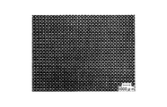
- FIG. 1 It is the figure which showed the form of the island-like pattern of the surface of the metal member used in Example 3.
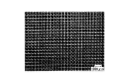
- FIG. It is the figure which showed the form of the island-like pattern of the surface of the metal member used in Example 4.
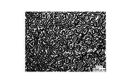
- FIG. It is the figure which showed the form of the island-like pattern of the surface of the metal member used in Example 5.
- FIG. It is the figure which showed the form of the island-like pattern of the surface of the metal member used in Example 6.
- FIG. 1 It is the figure which showed the form of the island-like pattern of the surface of the metal member used in Example 3.
- vacuum double-glazed glass First vacuum double-glazed glass
- FIG. 2 the multilayer glass by 1st Embodiment of this invention is demonstrated.
- vacuum double-glazed glass will be described as an example of double-glazed glass, and the configuration and characteristics thereof will be described.
- the present invention is not limited to “vacuum double-glazed glass”, and can be similarly provided to “non-vacuum” double-glazed glass.
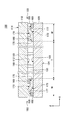
- FIG. 2 schematically shows an example of the structure of the vacuum double-glazed glass (first vacuum double-glazed glass).
- the first vacuum multi-layer glass 100 according to the first embodiment of the present invention includes a first glass substrate 110, a second glass substrate 120, and both glass substrates 110, 120.
- the gap 130 is configured, a plurality of spacers 190 for holding the gap 130, and a seal member 150 for holding the gap 130 in a sealed state.
- the seal member 150 is configured by laminating a first bonding layer 160, a metal member 155, and a second bonding layer 165 in this order.
- the first glass substrate 110 has a first inner surface 112 and a first outer surface 114.
- the first glass substrate 110 is disposed such that the first outer surface 114 side is the outside.
- the second glass substrate 120 has a second inner surface 122 and a second outer surface 124.
- the second glass substrate 120 is disposed so that the second outer surface 124 side is the outside. Accordingly, the gap 130 is formed between the first inner surface 112 of the first glass substrate 110 and the second inner surface 122 of the second glass substrate 120.
- the gap 130 is maintained in a vacuum state.
- the degree of vacuum of the gap 130 is not particularly limited, and may be any pressure lower than atmospheric pressure. In general, the pressure in the gap 130 is about 0.2 Pa to 0.001 Pa.
- the gap 130 may be filled with an inert gas such as argon at a pressure lower than atmospheric pressure. That is, in the present application, the “vacuum multilayer glass” is not limited to the one in which the pressure in the gap is in a vacuum state, and the term “vacuum multilayer glass” means that the pressure in the gap is less than atmospheric pressure. It shall mean all double-glazed glass.
- the vacuum multilayer glass 100 may have one or more spacers 190 in the gap 130.
- the spacer 190 has a role of holding the gap 130 in a desired shape.
- the gap 130 can be maintained in a desired shape without the spacer 190, for example, when the degree of vacuum of the gap 130 is low, or when an inert gas or the like is applied to the gap 130 at a certain pressure.
- the spacer 190 may be omitted.
- the seal member 150 is a member for holding the gap portion 130 in a hermetically sealed state, and the seal member 150 is configured over the entire periphery of the gap portion 130, that is, around the vacuum multilayer glass 100.
- the first bonding layer 160 of the seal member 150 is formed in an annular shape on the first inner surface 112 side of the first glass substrate 110 over the periphery of the first glass substrate 110.
- the second bonding layer 165 is formed in an annular shape on the second inner surface 122 side of the second glass substrate 120 over the periphery of the second glass substrate 120.
- the metal member 155 has a third surface 170 and a fourth surface 172 and has an annular shape around the periphery of the vacuum double-glazed glass 100.
- the metal member having an annular shape has a plate-shaped interior removed when the vacuum multilayer glass is viewed from the thickness direction (Z direction in FIG. 2), that is, in plan view, and has an outer contour and an inner side. It is a frame shape composed of a “frame” having an outline.
- the outer contour and / or inner contour of the metal member is not necessarily limited to a substantially rectangular parallelepiped shape such as a forehead, and may be, for example, a substantially trapezoidal shape, a substantially circular shape, or a substantially elliptical shape.
- the outer contour and the inner contour of the metal member do not necessarily have a similar shape, and both may have different shapes, for example.
- the third surface 170 of the metal member 155 is partially bonded to the first bonding layer 160, and the fourth surface 172 of the metal member 155 is partially bonded to the second bonding layer 165.
- the first bonding layer 160 is bonded to the third surface 170 of the metal member 155, and the second bonding layer 165 is bonded to the fourth surface 172 of the metal member 155.
- the region in contact with the first bonding layer 160 of the metal member 155 is referred to as a first contact region 175, and the region in contact with the second bonding layer 165 of the metal member 155 is referred to as the second contact region 175. This is referred to as a contact area 177.
- the gap 130 can be sealed.
- the first bonding layer 160 and the second bonding layer 165 do not overlap each other.
- the installation position is shifted. That is, in the example of FIG. 2, the first bonding layer 160 is disposed inside the second bonding layer 165.
- this is not always necessary, and the first bonding layer 160 and the second bonding layer 165 may partially or entirely overlap when viewed from above.
- the sealing member 150 is disposed on the inner side of the end surface of the first glass substrate or the second glass substrate when the vacuum multilayer glass 100 is viewed from the thickness direction. Since such a sealing member has a configuration in which the light-transmitting region of the vacuum double-glazed glass tends to be narrowed, the effect of the present invention is great.
- the seal member 150 of the vacuum double-glazed glass 100 includes a metal member 155 having a “step”. More specifically, when the metal member 155 is viewed in cross section, the third surface 170 of the metal member 155 has a height substantially equal to that of the first inner surface 112 of the first glass substrate 110, so that It has a contour that changes to a contact region 175 with one bonding layer 160. Similarly, the fourth surface 172 of the metal member 155 has a contour that changes from the contact region 177 with the second bonding layer 165 to a height that is substantially the same level as the second inner surface 122 of the second glass substrate 120.
- both surfaces 170 and 172 of the metal member 155 are shown by the outline bent linearly, the shape of the metal member 155 is not restricted to this. That is, both surfaces 170 and 172 of the metal member 155 may have a flat shape, a curved shape, or a contour composed of a combination of a straight line and a curved line.
- each member constituting the sealing member 150 is disposed between the first glass substrate 110 and the second glass substrate 120.
- the assembled assembly is configured.
- the assembly is then heat treated.
- the first and second bonding layers 160 and 165 are melted (softened) and solidified to form the seal member 150.
- both glass substrates 110 and 120 are joined through the seal member 150, and the vacuum double-glazed glass 100 is manufactured.
- the first contact region 175 and the second contact region 177 of the metal member 155 have island-shaped patterns having a plurality of concave or convex island portions. (Hereinafter, simply referred to as “island pattern”) has an uneven surface. Such an uneven surface can be prevented from flowing and spreading when the first and second bonding layers 160 and 165 are softened.
- first and second bonding layers 160 and 165 it is necessary to heat the seal member 150 partially or the entire assembly during the heat treatment. In order to obtain a bonding layer that provides reliable sealing, it is desirable to apply pressure in the thickness direction (Z direction in FIG. 2) of the vacuum double-glazed glass during the heat treatment.
- the first and second bonding layers pressed at the time of softening are not in the longitudinal direction of the metal member 155 (the direction along the periphery of the vacuum double-glazed glass; the direction toward the paper surface of FIG. 2) but in the width direction (vacuum compound). It is easy to spread in the direction perpendicular to the direction along the periphery of the layer glass (X direction in FIG. 2).
- the first and second bonding layers 160 and 165 are heated by the heat treatment of the seal member.
- the material melts (softens) the first and second bonding layers 160 and 165 are significantly suppressed from spreading beyond a predetermined range in the width direction of the metal member 155 (X direction in FIG. 2). Can do.
- the uneven surface of the island pattern is necessary at least in the first and second contact regions of the metal member, and the island pattern is not necessarily formed in a region away from the first and second contact regions. Absent.
- the thermal expansion of the metal member 155 is significantly larger than that of other members, wrinkles are generated in the metal member 155 when the sealing member is heat-treated when there is no uneven surface with an island pattern.
- This wrinkle forms a wrinkle that undulates mainly in the longitudinal direction of the metal member 155. That is, it becomes a ridge that forms a plurality of grooves in the width direction of the metal member 155.
- the melted (softened) first and second bonding layers (160, 165) are in contact with such wavy wrinkles, the molten (softened) bonding layers are wrinkled according to the strength of the contact pressure on the contact surface.
- the metal member 155 is spread so as to be pushed out into the groove in the width direction.
- the uneven surface of the island pattern it is considered that the wrinkled wrinkles are not formed, so that the spread of the molten (softened) bonding layers (160, 165) can be suppressed.
- the island pattern described below is a state before the metal member and the bonding layer are bonded. That is, it is a state of an island pattern before the bonding layer is heated and bonded to the metal member. Therefore, in the present invention, the island pattern after the bonding with the bonding layer is allowed to be deformed from the shape before the bonding.
- FIG. 3 shows a schematic enlarged top view of the first island pattern 200 formed in the first contact region 175 (or the second contact region 177; the same applies hereinafter) of the metal member 155.
- FIG. FIG. 4 is a schematic enlarged cross-sectional view of the first island pattern 200 formed in the first contact region 175 of the metal member 155.
- the first island pattern 200 includes a plurality of “island” portions that are concave or convex. More specifically, as shown in FIGS. 3 and 4, the first island pattern 200 includes a plurality of island portions 210 (210a, 210b, 210c) and an isolation portion 220 that separates the island portions from each other.
- the first island pattern 200 includes a plurality of island portions 210 (210a, 210b, 210c) and an isolation portion 220 that separates the island portions from each other.
- the isolation part 220 may exist in a continuous form as shown in FIG. 3, but may exist in a state of being separated into a plurality of small sections (that is, one of the adjacent island parts 210). Part may be substantially in contact).
- each of the island portions 210a, 210b, and 210c has a convex shape, and thus protrudes compared to the isolation portion 220 adjacent to each of the island portions 210a, 210b, and 210c. (That is, the island part 210 becomes a “mountain” and the separation part 220 becomes a “valley”).
- each of the island portions 210a, 210b, and 210c has a concave shape, and therefore may be recessed as compared with the isolation portion 220 adjacent to each of the island portions 210a, 210b, and 210c. (That is, the island part 210 becomes a “valley” and the separation part 220 becomes a “mountain”).
- each island part 210a, 210b, 210c may differ.
- each island part 210 may be arrange
- the form of the island pattern is not limited to this. For example, a plurality of islands may be regularly arranged along each of at least two different directions, or irregularly in various directions of two or more different directions as shown in FIG. May be arranged.
- each island part has a pitch of 300 ⁇ m or more and 24000 ⁇ m or less regardless of regular or irregular.
- the pitch By setting the pitch to 24000 ⁇ m or less, the spread of the bonding layer can be suppressed. Manufacturing is facilitated by setting the pitch to 300 ⁇ m or more.
- the islands may be arranged at a pitch of 300 ⁇ m or more and 15000 ⁇ m or less, preferably a pitch of 300 ⁇ m or more and 10000 ⁇ m or less, more preferably a pitch of 300 ⁇ m or more and 5000 ⁇ m or less.
- each island part 210 has a pitch of 300 ⁇ m or more and 10,000 ⁇ m or less, and preferably a pitch of 400 ⁇ m or more and 4000 ⁇ m or less.
- the island portion 210 having a largest dimension in each island 210 (e.g., the island portion 210 b) is referred to as a top-Oshima unit 210 max, bear any two points on the contour of the island portion 210 max
- the length of the straight line having the maximum length among the straight lines that can be arranged in the island part 210 max is referred to as “maximum length L max ”.
- the maximum length L max of the plurality of island portions is preferably 10 ⁇ m or more and 21000 ⁇ m or less. By setting the pitch to 21000 ⁇ m or less, the bonding layer can be prevented from spreading.
- the maximum length L max is preferably 100 ⁇ m or more and 10,000 ⁇ m or less, and more preferably 300 ⁇ m or more and 5000 ⁇ m or less.
- the maximum length L max is, for example, in the range of 700 ⁇ m to 21000 ⁇ m, and preferably in the range of 700 ⁇ m to 4000 ⁇ m.
- the height level of the separation portion 220 is different in each place. Also good. Similarly, the height level of each island part 210a, 210b, 210c may be different. Therefore, the unevenness difference H between the island part 210 and the separation part 220 may be different in each place.
- the “concave / convex difference H” means a difference in height H between the island part 210 and the separation part 220 adjacent to the island part 210 as shown in FIG. Particularly, in the island pattern, the largest unevenness difference H is referred to as “maximum unevenness difference H max ”.
- the maximum unevenness difference H max of the plurality of island portions is 10 ⁇ m or more and 300 ⁇ m or less.
- the maximum unevenness difference H max is preferably 30 ⁇ m or more and 270 ⁇ m or less, and more preferably 40 ⁇ m or more and 250 ⁇ m or less.
- the maximum unevenness difference H max is, for example, in the range of 50 ⁇ m to 270 ⁇ m, and preferably in the range of 90 ⁇ m to 230 ⁇ m.
- the maximum unevenness difference Hmax / average pitch which is the ratio of the maximum unevenness difference Hmax and the average pitch (average value of the maximum pitch and the minimum pitch) of the arrangement of the islands, is 0.02 or more, for example. Is preferred.
- the ratio of the maximum unevenness difference H max / average pitch is 0.02 or more, the first contact region of the metal member 155 is caused by the difference in thermal expansion between the metal member 155 and the bonding layers 160 and 165 during the heat treatment. It is considered that wrinkles generated so as to wave in the longitudinal direction of the metal member 155 are less likely to occur between the 175 and the first bonding layer 160 and between the second contact region 177 and the second bonding layer 165. That is, it is a shape that can ease the difference in thermal expansion. For this reason, the effect of suppressing the horizontal expansion of the molten (softened) bonding layer (160, 165) is increased.
- the ratio of the maximum unevenness difference H max / average pitch is preferably 0.05 or more.
- the island pattern may be configured by two-dimensionally regularly arranging a plurality of island portions having substantially the same shape.
- an example of an island pattern having such a periodic structure of island portions will be described with reference to FIGS. 5 and 6.
- FIG. 5 shows a schematic enlarged top view of the second island pattern.
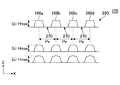
- FIG. 6 is a schematic enlarged sectional view of the second island pattern.
- the second island pattern 250 is formed between a plurality of island portions 260 (260a, 260b, 260c, 260d) having a substantially circular shape in plan view and between the adjacent island portions 260. And an isolation part 270 arranged.
- the second island pattern 250 is configured by regularly arranging the island portions 260 in two different directions which are two different directions, that is, the X direction and the Y direction in FIG.
- each island part 260a, 260b, 260c, 260d has a convex form, Therefore, it protrudes compared with the isolation
- each of the islands 260a, 260b, 260c, 260d has a concave shape, and therefore may be recessed as compared to the isolation part 270 (ie, the island 260 is a “valley”. And the separation part 270 becomes a “mountain”).
- first direction In each of the island portions 260, two different directions are a first direction (X direction in FIG. 5) and a second direction (Y direction in FIG. 5), and each along the first direction and the second direction. , Regularly arranged.
- the arrangement pitch of the island portions 260 in the first direction is constant at Px.
- the arrangement pitch of the island portions 260 in the second direction is constant at Py.
- Px and / or Py are, for example, in the range of 300 ⁇ m to 20000 ⁇ m, and preferably in the range of 400 ⁇ m to 4000 ⁇ m.
- the arrangement pitch Px in the first direction and the arrangement pitch Py in the second direction may be different.
- Each island 260 is substantially the same in size and shape, and the diameter of the island 260 is the maximum length L max . Further, the unevenness difference H is the same at any location, and the unevenness difference H is the maximum unevenness difference Hmax .
- the cross-sectional shape of the island part of the second island pattern is not limited to this.
- a form as shown in FIG. 6B and FIG. 6C may be used.
- the island part of FIG.6 (b) and FIG.6 (c) is formed in mountain shape, and the ridgeline has a curve.
- the top of the island is arcuate.
- the top part of the island part has an arc shape close to a plane, and the shape of FIG. 6B is slightly crushed.
- the maximum length L max of the island portion 260 is, for example, in the range of 10 ⁇ m to 4000 ⁇ m, and preferably in the range of 30 ⁇ m to 1000 ⁇ m.
- the maximum unevenness difference H max of the island part 260 is, for example, in the range of 10 ⁇ m to 250 ⁇ m, and preferably in the range of 90 ⁇ m to 230 ⁇ m.
- the maximum unevenness difference Hmax / average pitch which is the ratio between the maximum unevenness difference Hmax and the average pitch (average value of Px and Py), is, for example, 0.05 or more. It is preferable.
- each island 260 has a substantially circular shape in plan view.
- each island part 260 may have a shape such as an ellipse, a triangle, a quadrangle, or a pentagon or more polygon in plan view.
- the cross section of each island part 260 may have a shape such as a triangle, a square, or a rectangle in addition to a trapezoid.
- the island pattern may be configured by an array pattern of island portions 260 different from those in FIGS. 5 and 6.
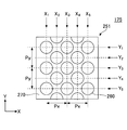
- the island pattern may have an array pattern of island portions 260 as shown in FIG.
- the island pattern (third island pattern) 251 is regularly arranged along the first direction (X direction in FIG. 7) and the second direction (Y direction in FIG. 7).
- the island portion 260 is formed.
- this third island pattern 251 when the columns X 1 to X 5 of the island portion 260 at the same X coordinate are defined along the first direction (X direction), In X1, X3, and X5 and rows X2, X4, and X6, the position of the island portion 260 in the second direction (that is, the Y coordinate) is shifted by 1/2 Py.
- the rows Y1 to Y5 of the island portion 260 at the same Y coordinate are defined along the second direction (Y direction)
- the rows Y1, Y3 and Y5 and the rows Y2, Y4 and Y6 are: The position of the island portion 260 in the first direction (that is, the X coordinate) is shifted by 1/2 Px.
- the island pattern may be configured by any arrangement pattern of the island portions 260.
- various modes can be assumed as the configuration of the island pattern. This will be apparent to those skilled in the art.
- the second vacuum multilayer glass 300 basically has the same configuration as the first vacuum multilayer glass 100 shown in FIG. Therefore, in FIG. 8, the same reference numerals as those in FIG. 2 plus 200 are used for the same members as in FIG. However, the second vacuum multilayer glass 300 shown in FIG. 8 is different from the first vacuum multilayer glass 100 shown in FIG. 2 in the sealing member.
- the second vacuum double-glazed glass 300 has a seal member 350 disposed over the entire periphery of the gap portion 330, and the cross-section of the seal member 350 is substantially “Z-shaped”. More specifically, the seal member 350 joins a metal member 355 having a Z-shaped cross section to the first outer surface 314 of the first glass substrate 310 via the first joining layer 360, and It is configured by bonding to the second inner surface 322 of the second glass substrate 320 via the two bonding layers 365.
- the second vacuum double-glazed glass 300 a region in contact with the first bonding layer 360 of the metal member 355, that is, a region in contact with the first contact region 375 and the second bonding layer 365, That is, it should be noted that the second contact region 377 is present on the third surface 370 side of the metal member 355.
- island-like patterns are formed in the first contact region 375 and the second contact region 377 of the metal member 355.
- the second vacuum multilayer glass 300 the same effect as the first vacuum multilayer glass 100 is obtained, that is, the first and second bonding layers 360 and 365 are melted (softened) by the heat treatment. In this case, it is possible to significantly suppress the first and second bonding layers 360 and 365 from spreading in the width direction of the metal member 355 (X direction in FIG. 8). Therefore, also in the second vacuum multilayer glass 300, it is possible to significantly suppress the narrowing of the light transmission region in the central portion.
- the third vacuum multilayer glass 400 basically has the same configuration as the first vacuum multilayer glass 100 shown in FIG. Therefore, in FIG. 9, the same reference numerals as those in FIG. 2 plus 300 are used for the same members as in FIG. However, the third vacuum multilayer glass 400 shown in FIG. 9 is different from the first vacuum multilayer glass 100 shown in FIG. 2 in the sealing member.
- the third vacuum double-glazed glass 400 includes a seal member 450 disposed over the entire periphery of the gap portion 430, and the seal member 450 is configured to have a substantially “bracket” shape in cross section. . More specifically, the seal member 450 joins the metal member 455 having a square bracket cross section to the first outer surface 414 of the first glass substrate 410 via the first joining layer 460, and It is configured by bonding to the second outer surface 424 of the second glass substrate 420 via the two bonding layers 465.
- island-like patterns are formed in the first contact region 475 and the second contact region 477 of the metal member 455.
- the effect similar to the 1st vacuum multilayer glass 100 is acquired, ie, the 1st and 2nd joining layers 460 and 465 are fuse
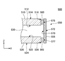
- FIG. 10 an example of the structure of the vacuum double-glazing (4th vacuum double-glazing) by 4th Embodiment of this invention is shown roughly.
- the fourth vacuum multilayer glass 500 basically has the same configuration as the first vacuum multilayer glass 100 shown in FIG. Accordingly, in FIG. 10, the same reference numerals as those in FIG. 2 plus 400 are used for the same members as in FIG. However, the fourth vacuum double-glazed glass 500 shown in FIG. 10 is different from the first vacuum double-glazed glass 100 shown in FIG.
- the fourth vacuum double-glazed glass 500 has a seal member 550 disposed over the entire periphery of the gap portion 530, and the cross-section of the seal member 550 is substantially “I”. More specifically, the seal member 550 joins a metal member 555 having an I-shaped cross section to the end surface 516 of the first glass substrate 510 via the first joining layer 560 and the second joining layer 565. It is comprised by joining to the end surface 526 of the 2nd glass substrate 520 via.
- a region in contact with the first bonding layer 560 of the metal member 555 that is, a region in contact with the first contact region 575 and the second bonding layer 565, That is, it should be noted that the second contact region 577 is present on the third surface 570 side of the metal member 555.
- island-like patterns are formed in the first contact region 575 and the second contact region 577 of the metal member 555.
- the effect similar to the 1st vacuum multilayer glass 100 is acquired, ie, the 1st and 2nd joining layers 560 and 565 are fuse
- the first and second bonding layers 560 and 565 are respectively connected to the first and second bonding layers 560 and 565 without protruding from the end surfaces of the first and second glass substrates 510 and 520. It becomes possible to install in the range of the width of the end surface of the 1st and 2nd glass substrate 510,520.
- Glass substrate 110, 120 The composition of the glass constituting the glass substrates 110 and 120 is not particularly limited.
- the glass of the glass substrates 110 and 120 may be, for example, soda lime glass and / or alkali-free glass.
- the compositions of the first glass substrate 110 and the second glass substrate 120 may be the same or different.
- the spacer 190 may have the same material, shape, and / or dimensions as the spacer used in conventional vacuum double glazing.
- the height of the spacer 190 that is, the thickness of the gap 130 is preferably in the range of 0.015 mm to 1 mm, and 0.05 mm to 0 mm when the gap 130 is in a pressure state below atmospheric pressure. More preferably, it is in the range of 5 mm.
- the thickness of the gap 130 is preferably in the range of 0.015 mm to 15.7 mm, and in the range of 3 mm to 13 mm. It is more preferable that
- the seal member 150 includes the first and second bonding layers 160 and 165 and the metal member 155.
- the seal width W of the seal member 150 is not particularly limited. However, it should be noted that in one embodiment of the present invention, as described above, the seal width W of the seal member 150 can be significantly shortened.
- the seal width W of the seal member 150 is, for example, in the range of 3 mm to 50 mm.
- the bonding layers 160 and 165 constituting the seal member 150 may be made of any material as long as the bonding layers 160 and 165 have bonding properties to the glass substrates 110 and 120 and the metal member 155. Further, the first bonding layer 160 and the second bonding layer 165 may be the same or different.
- the bonding layers 160 and 165 may be vitrified layers.
- the vitrified layer is formed by firing a paste containing glass frit.
- the vitrified layer contains a glass component, but may further contain ceramic particles.
- the composition of the glass component contained in the vitrified layer is not particularly limited.
- the glass component contained in the vitrified layer may be, for example, ZnO—Bi 2 O 3 —B 2 O 3 or ZnO—SnO—P 2 O 5 glass.
- Table 1 shows an example of the composition of a ZnO—Bi 2 O 3 —B 2 O 3 -based glass that can be used as a glass component contained in the vitrified layer.
- Table 2 shows an example of the composition of ZnO—SnO—P 2 O 5 based glass that can be used for the glass component contained in the vitrified layer.
- At least one of the bonding layers 160 or 165 may include a metal spray film on the surface.
- the metal spray film is formed on the surface of the first glass substrate, and the first bonding is performed on the metal spray film by, for example, brazing or soldering.
- Layer 160 may be formed.
- the metal sprayed film may be formed in an annular shape on one surface of the glass substrate by, for example, an arc spraying method or a plasma spraying method.
- the material of the metal sprayed film is not limited to this, but may be, for example, copper (and copper alloy), aluminum (and aluminum alloy), zinc (and zinc alloy), and the like.
- the bonding layers 160 and 165 may include any material such as ceramics, glass, and metal as long as they can be bonded to the metal member 155.
- the bonding layers 160 and 165 are not necessarily formed of a single layer, and may be formed of a plurality of layers.
- the thickness of the bonding layer is not limited to this.
- the thickness when the gap 130 is in a pressure state below atmospheric pressure, the thickness is in the range of 10 ⁇ m to 1000 ⁇ m, and the gap 130 has a certain amount of inert gas. In the case of filling at a pressure of 10 ⁇ m to 15000 ⁇ m, it may be in the range.
- the maximum width (length in the X direction) of the first bonding layer 160 and / or the second bonding layer 165 is not limited to this, but is, for example, in the range of 0.1 mm to 15 mm. This width may be in the range of 1 mm to 7 mm.
- the cross sections of the first bonding layer 160 and the second bonding layer 165 are both shown in a substantially rectangular shape with rounded corners.
- the cross sections of the first bonding layer 160 and the second bonding layer 165 may have other shapes such as a substantially elliptical shape and a substantially trapezoidal shape, for example.
- the shapes of the first bonding layer 160 and the second bonding layer 165 may be different.
- Metal member 155 The kind of metal material that constitutes the metal member 155 is not particularly limited.
- the metal member 155 may be selected from, for example, aluminum and aluminum alloy, copper and copper alloy, titanium and titanium alloy, and stainless steel.
- the metal member 155 is preferably made of a relatively soft material. Thereby, it becomes easy to form an island pattern.
- the widths of the first and second contact regions 175 and 177 are substantially equal to the widths of the first and second bonding layers 160 and 165, respectively. That is, the widths of the first and second contact regions 175 and 177 may be, for example, in the range of 0.1 mm or more and 15 mm or less.
- the metal member 155 is a foil or a plate, and when the gap 130 is in a pressure state less than atmospheric pressure, the metal member 155 has a thickness in the range of 5 ⁇ m to 500 ⁇ m, preferably in the range of 50 ⁇ m to 200 ⁇ m.
- the gap 130 When the gap 130 is filled with an inert gas or the like at a certain pressure, it has a thickness in the range of 5 ⁇ m to 700 ⁇ m, preferably in the range of 50 ⁇ m to 500 ⁇ m. May be.
- the shape of the metal member 155 in the preparatory stage is not particularly limited as long as the final provided shape is an annular shape around the vacuum double-glazed glass. Therefore, for example, the annular metal member 155 may be configured by joining a plurality of elongated plate-like members. Alternatively, the annular metal member 155 may be provided as an integrated product (seamless member) by cutting the plate-like member into an annular shape or punching the plate-like member into an annular shape. Further, the metal member 155 may be configured by laminating and bonding a plurality of metal members in the thickness direction of the vacuum multilayer glass.
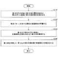
- FIG. 11 the flowchart of an example of the manufacturing method of the vacuum multilayer glass by one Embodiment of this invention is shown.
- the manufacturing method of the vacuum multilayer glass by one Embodiment of this invention is the following. Forming a first bonding layer around the first glass substrate and forming a second bonding layer around the second glass substrate (S110); Preparing a metal member having an annular shape along the periphery of the first or second glass substrate having an irregular surface of an island pattern in the first and second contact regions (S120); The first glass is formed by combining the metal members such that the first bonding layer of the first glass substrate and the second bonding layer of the second glass substrate are in contact with the first and second contact regions of the metal member, respectively. Laminating the substrate and the second glass substrate to form an assembly (S130); Heating at least the first and second bonding layers of the assembly to bond the first and second bonding layers and the metal member (S140); Have
- vacuum multilayer glass manufacturing method described below can be used for manufacturing vacuum multilayer glass having the structure shown in FIGS. 1 and 8 to 10 by simple modifications. It is clear to the contractor.
- Step S110 First, the first and second glass substrates 110 and 120 are prepared.
- first bonding layer 160 is formed on the first inner surface 112 of the first glass substrate 110
- second bonding layer 165 is formed on the second inner surface 122 of the second glass substrate 120. Is done.
- the first glass solidified layer is formed around the first surface 112 of the first glass substrate 110 by taking the case where the first bonding layer 160 is a glass solidified layer as an example.
- the paste includes glass frit, ceramic particles, a polymer, an organic binder, and the like.
- the ceramic particles may be omitted.
- the glass frit eventually becomes a glass component constituting the first vitrified layer.
- the prepared paste is applied around the first surface 112 of the first glass substrate 110.
- the first glass substrate 110 containing the paste is dried.
- the conditions for the drying treatment are not particularly limited as long as the solvent in the paste is removed.
- the drying process may be performed, for example, by holding the first glass substrate 110 at a temperature of 100 ° C. to 200 ° C. for about 30 minutes to 1 hour.
- the first glass substrate 110 is heat-treated at a high temperature.
- the conditions for the heat treatment are not particularly limited as long as the organic binder contained in the paste is removed.
- the heat treatment may be performed by, for example, holding the first glass substrate 110 in the temperature range of 300 ° C. to 470 ° C. for about 30 minutes to 1 hour in the atmosphere. Thereby, a paste is baked and a 1st glass solidified layer is formed. At this time, the thickness of the solidified layer is 10 ⁇ m to 1000 ⁇ m.
- a second glass solidified layer is formed around the third surface 122 of the second glass substrate 120.
- Step S120 Next, an annular metal member 155 is prepared along the periphery of the vacuum multilayer glass.
- the annular metal member 155 may be an integrated product (seamless member) without a joint portion or a combination of a plurality of members.
- Integral product (seamless member) annular metal member 155 can be easily manufactured, for example, by preparing a plate-like metal member and press cutting so as to cut out the inside of the plate-like metal member.
- the metal member 155 may have a substantially flat shape without the “step” as shown in FIG.
- first and second contact regions 175 and 177 of the metal member 155 corresponds to a region where the metal member 155 is in contact with the first bonding layer 160 in the subsequent steps
- second contact region 177 is the second bonding region where the metal member 155 is the second bonding. This corresponds to the region in contact with the layer 165.
- the uneven surface of the island pattern does not necessarily need to be formed only in the first and second contact regions 175 and 177.
- the uneven surface of the island pattern may be formed on the entire first surface 170 and second surface 172 of the metal member 155.
- the method for forming the island pattern is not particularly limited.
- the island pattern may be formed by embossing the first and second contact regions 175 and 177 of the metal member 155, for example.
- the island pattern may be formed by applying dimple processing or press processing to a predetermined region of the metal member 155.
- the island pattern may be formed in a predetermined region of the metal member 155 by performing stamping, knurling, corrugating, or groove processing.
- an island pattern can be formed in a predetermined region of the metal member 155 by various methods.
- Step S130 an assembly is configured by combining the first and second glass substrates 110 and 120 and the annular metal member 155.
- the metal member 155 is arranged such that the third surface 170 is on the first glass substrate 110 side and the fourth surface 172 is on the second glass substrate 120 side. In addition, the metal member 155 is disposed such that the first contact region 175 is in contact with the first bonding layer 160 and the second contact region 177 is in contact with the second bonding layer 165.
- one or more spacers 190 may be disposed between the first glass substrate 110 and the second glass substrate 120 as necessary.
- a pressing force may be applied to the assembly from the first glass substrate 110 and / or the second glass substrate 120 side.
- the metal member 155 may be formed with a “step” as shown in FIG.
- Step S140 Next, the assembly is heated.
- the heating temperature and the heating time vary depending on the softening point of the vitrified layer.
- the assembly is placed in a chamber at a temperature of about 350 ° C. to about 600 ° C., preferably 470 ° C. to 560 ° C. (eg 490 ° C.) for about 5 seconds to 180 minutes, preferably about 15 seconds to 30 minutes (eg 20 Min)), after holding, it may be removed from the chamber and cooled to room temperature.
- the first and second vitrified layers 160 and 165 may be pressurized by pressurizing the third surface 170 and the fourth surface 172 of the metal member 155 during the heat treatment of the assembly.
- the bonding strength with the metal member 155 is increased.
- a “step” as shown in FIG. 2 can be formed in the metal member 155.
- the uneven surface of an island-like pattern is comprised in the metal member 155, it is thought that it can suppress that the glass solidification layers 160 and 165 fuse
- the first and second vitrified layers 160 and 165 are melted (softened) by heating the assembly. For this reason, the metal member 155 is bonded to the first vitrified layer 160 in the first contact region 175, and is bonded to the second vitrified layer 165 in the second contact region 177. Therefore, after the heat treatment of the assembly, a gap 130 surrounded by the seal member 150 is formed between the first and second glass substrates 110 and 120.
- the inside of the gap 130 is subjected to a decompression process using the openings provided in advance in the first and / or second glass substrates 110 and 120.
- the gas in the gap 130 may be replaced with an inert gas.
- the opening used for the decompression process is sealed. Thereby, the vacuum multilayer glass 100 is manufactured.
- island-shaped patterns are formed in the first contact region 175 and the second contact region 177 of the metal member 155. For this reason, the first and second vitrified layers 160 and 165 melted (softened) by heating are difficult to spread in the horizontal direction (X direction in FIG. 2), and the first and second contact regions 175 and 177 Stay.
- the seal member 150 finally manufactured has a significantly short seal width W.
- this makes it possible to suppress the narrowing of the light-transmitting region due to the provision of the seal member 150 and to manufacture the vacuum double-glazed glass 100 having a significantly wide light-transmitting region.
- Example 1 Multi-layer glass was produced by the method shown in FIG. 11 described above, and the spread state of the bonding layer in the seal member was evaluated. In addition, what has the sealing member shown in FIG. 2 was employ
- first glass substrate and a second glass substrate were prepared.
- the dimensions of each glass substrate are 600 mm long ⁇ 600 mm wide ⁇ 6 mm thick.
- the paste was applied on one surface (first surface) of the first glass substrate in a ring shape along the periphery of the first glass substrate.
- the paste was prepared by mixing glass frit and an organic binder.
- the glass frit having the composition shown in Table 1 was used.
- the first glass substrate was heat-treated at 490 ° C. for 30 minutes in the atmosphere to form a circular first glass solidified layer.
- the external dimension of the first vitrified layer was 598 mm long ⁇ 598 mm wide. In each side, the width of the first vitrified layer (that is, the difference between the outer shape and the inner shape) was about 1.8 mm.
- annular second bonding layer was formed on one surface (third surface) of the second glass substrate along the periphery of the second glass substrate.
- the external dimensions of the second bonding layer were 572 mm long ⁇ 572 mm wide.
- the width of the second bonding layer was about 1.8 mm.
- annular metal member was prepared.
- the external dimensions of the metal member are 600 mm long ⁇ 600 mm wide ⁇ 50 ⁇ m thick.
- the annular metal member has a frame shape, and the width of each side of the frame is 15 mm.
- annular metal member an aluminum foil having an island-like convex pattern embossed on both sides was used.
- FIG. 12 shows an aspect of the island pattern.
- each island part is constituted by a convex part, has a substantially square shape in plan view, and has a maximum length L max of 550 ⁇ m.
- the minimum pitch of the islands is 500 ⁇ m
- the maximum pitch is 720 ⁇ m
- the average pitch is 610 ⁇ m.
- the ratio of maximum unevenness difference H max / average pitch is 0.151.
- the minimum pitch is a measured value of the period when the period is measured in the direction in which the uneven period of the island pattern is minimized, for example, from the top of a certain island (or the center when the top is a plane), It means the minimum value of the distance to the top of the nearest island part, and the maximum pitch means the measured value of the period when the period is measured in the direction where the uneven period becomes the maximum, and the average pitch means both Means the average.
- first glass substrate and the second glass substrate were laminated through the above-described metal members to form an assembly.
- each member was laminated such that the first glass solidified layer of the first glass substrate and the second glass solidified layer of the second glass substrate were in contact with the metal member.
- the assembly was heat-treated at 490 ° C. for 30 minutes in the atmosphere to produce a multilayer glass.
- the widths of the first and second vitrified layers were observed.
- the width of the first and second glass solidified layers was about 3.3 mm at the maximum, and it was confirmed that the first and second glass solidified layers did not spread much in the horizontal direction.
- Example 2 By the same method as in Example 1, a multi-layer glass was produced, and the spread state of the bonding layer in the sealing member was evaluated.
- Example 2 an aluminum foil (thickness: 50 ⁇ m) having an island pattern in the form shown in FIG. 13 was used as the metal member on both surfaces.
- the island portions are regularly arranged two-dimensionally.
- Each island portion includes a convex portion has the shape of a plan view a square, the maximum length L max is 710 .mu.m.
- the minimum pitch of the island part is 620 ⁇ m, the maximum pitch is 870 ⁇ m, and the average pitch is 750 ⁇ m.
- the ratio of the maximum unevenness difference H max / average pitch is 0.202. Other conditions are the same as in the first embodiment.
- the width of the 1st and 2nd glass solidification layer of the multilayer glass after preparation was observed.
- the width of the first and second vitrified layers was about 3.0 mm at the maximum. Since the widths of the first and second vitrified layers before the heat treatment were about 1.8 mm, the first and second vitrified layers may not spread much in the horizontal direction even after the heat treatment. confirmed.
- Example 3 Multilayer glass was produced by the same method as in Example 1, and the spread state of the glass solidified layer in the sealing member was evaluated.
- Example 3 an aluminum foil (thickness: 50 ⁇ m) having an island pattern in the form shown in FIG. 14 was used as the metal member on both surfaces.
- the island portions are irregularly arranged, and each island portion is formed in a convex shape.
- the maximum length L max of the island part is 2000 ⁇ m.
- the minimum pitch of the islands is 400 ⁇ m, the maximum pitch is 2400 ⁇ m, and the average pitch is 1400 ⁇ m.
- the ratio of the maximum unevenness difference H max / average pitch is 0.102. Other conditions are the same as in the first embodiment.
- the width of the 1st and 2nd glass solidification layer of the multilayer glass after preparation was observed.
- the width of the first and second vitrified layers was about 3.9 mm at the maximum. Since the widths of the first and second vitrified layers before the heat treatment were about 1.8 mm, the first and second vitrified layers may not spread much in the horizontal direction even after the heat treatment. confirmed.
- Example 4 Multilayer glass was produced by the same method as in Example 1, and the spread state of the glass solidified layer in the sealing member was evaluated.
- Example 4 an aluminum foil (thickness: 80 ⁇ m) having an island pattern in the form shown in FIG. 15 was used as the metal member on both surfaces.
- the island portions are irregularly arranged, and each island portion is formed in a convex shape.
- the maximum length L max of the island is 1800 ⁇ m.
- the minimum pitch of the island is 400 ⁇ m, the maximum pitch is 3600 ⁇ m, and the average pitch is 2000 ⁇ m.
- the ratio of maximum unevenness difference H max / average pitch is 0.051. Other conditions are the same as in the first embodiment.
- the width of the 1st and 2nd glass solidification layer of the multilayer glass after preparation was observed.
- the maximum width of the first and second vitrified layers was about 3.3 mm. Since the widths of the first and second vitrified layers before the heat treatment were about 1.8 mm, the first and second vitrified layers may not spread much in the horizontal direction even after the heat treatment. confirmed.
- Example 5 Multilayer glass was produced by the same method as in Example 1, and the spread state of the glass solidified layer in the sealing member was evaluated.
- Example 5 an aluminum foil (thickness: 50 ⁇ m) having an island pattern in the form shown in FIG. 16 was used as the metal member on both surfaces.
- the island portions are regularly arranged in a two-dimensional manner, and each island portion is constituted by a convex portion and has a substantially rhombus shape in plan view.
- the maximum length L max is 2000 ⁇ m.
- the minimum pitch of the island portion is 2700 ⁇ m, the maximum pitch is 3700 ⁇ m, and the average pitch is 3200 ⁇ m.
- the ratio of the maximum unevenness difference H max / average pitch is 0.070.
- Other conditions are the same as in the first embodiment.
- the width of the 1st and 2nd glass solidification layer of the multilayer glass after preparation was observed.
- the maximum width of the first and second vitrified layers was about 2.3 mm. Since the widths of the first and second vitrified layers before the heat treatment were about 1.8 mm, the first and second vitrified layers may not spread much in the horizontal direction even after the heat treatment. confirmed.
- Example 6 Multilayer glass was produced by the same method as in Example 1, and the spread state of the glass solidified layer in the sealing member was evaluated.
- Example 6 an aluminum foil having island-like patterns in the form shown in FIG. 17 was used on both surfaces as the metal member.
- the island portions are irregularly arranged, and each island portion is formed in a convex shape.
- the maximum length L max of the island is 21000 ⁇ m.
- the minimum pitch of the island is 2000 ⁇ m, the maximum pitch is 24000 ⁇ m, and the average pitch is 13000 ⁇ m.
- the ratio of the maximum unevenness difference H max / average pitch is 0.020. Other conditions are the same as in the first embodiment.
- the width of the 1st and 2nd glass solidification layer of the multilayer glass after preparation was observed.
- the maximum width of the first and second vitrified layers was about 8.6 mm. Since the width of the first and second vitrified layers before the heat treatment was about 1.8 mm, the effect of suppressing the spread of the first and second vitrified layers by the metal member used in Example 6 is It was found that it was not as remarkable as the other examples.
- Multilayer glass was produced by the same method as in Example 1, and the spread state of the glass solidified layer in the sealing member was evaluated.
- Comparative Example 1 aluminum foil having no island pattern on both surfaces, that is, smooth surfaces, was used as the metal member.
- the thickness of the aluminum foil is 50 ⁇ m.
- Other conditions are the same as in the first embodiment.
- the width of the 1st and 2nd glass solidification layer of the multilayer glass after preparation was observed.
- the width of the first and second vitrified layers was about 9.8 mm. Since the widths of the first and second vitrified layers before the heat treatment were about 1.5 mm, the first and second vitrified layers tend to spread greatly in the horizontal direction after the heat treatment. Was confirmed.
- Table 3 below collectively shows the specifications of the metal members used in Examples 1 to 6 and Comparative Example 1, the values of the width of the vitrified layer before and after the heat treatment, and the like.
- the present invention can be used for vacuum double glazing and the like used for window glass of buildings.
Landscapes
- Engineering & Computer Science (AREA)
- Civil Engineering (AREA)
- Structural Engineering (AREA)
- Joining Of Glass To Other Materials (AREA)
- Securing Of Glass Panes Or The Like (AREA)
Abstract
相互に対向する第1のガラス基板と第2のガラス基板との間に間隙部を備える複層ガラスであって、前記間隙部は、当該複層ガラスの周囲でシール部材によって密閉され、前記シール部材は、当該複層ガラスを厚さ方向から見たとき、当該複層ガラスの周囲に沿った環状を有する金属部材と、第1の接合層と、第2の接合層とを有し、前記金属部材は、前記第1の接合層と接触する第1の接触領域と、前記第2の接合層と接触する第2の接触領域とを有し、前記第1の接合層は、前記第1のガラス基板の周囲に形成され、前記第1の接触領域に結合され、前記第2の接合層は、前記第2のガラス基板の周囲に形成され、前記第2の接触領域に結合され、前記金属部材の第1の接触領域および第2の接触領域には、凹状または凸状の複数の島部を含む島状パターンの凹凸表面が形成されていることを特徴とする複層ガラス。
Description
本発明は、複層ガラスおよびその製造方法に関する。
一対のガラス基板を間隙部を介して積層し、該間隙部を低圧または真空状態に保持して構成される、いわゆる「真空複層ガラス」は、優れた断熱効果を有するため、例えばビルおよび住宅等の建築物用の窓ガラス用途に広く利用されている。
真空複層ガラスにおいては、間隙部を真空状態に保持するために該間隙部の周囲に設置されるシール部材のシール性能が、真空複層ガラス全体の断熱性に大きな影響を及ぼす。シール部材のシール性が劣る場合、シール部材を介して、大気中の空気および/または水蒸気等の成分が間隙部に容易に侵入し、これにより間隙部の真空度が低下してしまうからである。このため、よりシール性に優れたシール部材の検討が進められている。
特に、最近では、金属部材と接合層とで構成されたシール部材が開発されている。例えば、特許文献1には、真空複層ガラスにおいて、金属部材とガラスフリットとを組み合わせてシール部材を形成することが開示されている。
前述のように、特許文献1には、金属部材とガラスフリットとを組み合わせたシール部材が開示されている。
例えば、特許文献1には、図1に示すように、第1のガラス基板2と、第2のガラス基板3と、両ガラス基板の間にスペーサ5を介して構成された間隙部6と、該間隙部6の周囲に構成されたシール部材70とを備える真空複層ガラス1が示されている。シール部材70は、第1のガラスフリット25、U字型金属部材71、および第2のガラスフリット26を、この順に積層することにより構成される。
なお、図1に示すような真空複層ガラス1を製造する際には、まず、第1のガラス基板2と第2のガラス基板3の間に、シール部材70を構成する各部材を配置した組立体が構成される。次に、この組立体が加熱処理される。加熱処理によって、ガラスフリット25、26が溶融(軟化)、固化し、シール部材70が構成される。また、このシール部材70を介して、両ガラス基板2、3が接合され、真空複層ガラス1が構成される。
ここで、組立体の加熱処理の際に、溶融(軟化)したガラスフリット25、26は、初期の位置から、図の水平方向(X方向)に広がる可能性がある。このため、従来のシール部材70では、シール幅(図の符号W)を短くすることが難しいという問題がある。換言すれば、従来の真空複層ガラス1では、加熱処理の際のガラスフリット25、26の水平方向の広がりを考慮して、シール部材70のシール幅Wを設計する必要がある。
しかしながら、そのようなシール幅Wの広いシール部材を適用した場合、製造される真空複層ガラスの中央の透明な部分、すなわち透光領域Tが狭小化されてしまうという問題が生じる。
このため、シール部材による透光領域Tの狭小化が抑制され、広い透光領域Tを確保することの可能な複層ガラスが要望されている。
本発明は、このような背景に鑑みなされたものであり、本発明では、シール部材による透光領域の狭小化を有意に抑制することが可能な複層ガラスおよびその製造方法を提供することを目的とする。
本発明では、相互に対向する第1のガラス基板と第2のガラス基板との間に間隙部を備える複層ガラスであって、
前記間隙部は、当該複層ガラスの周囲でシール部材によって密閉され、
前記シール部材は、当該複層ガラスを厚さ方向から見たとき、当該複層ガラスの周囲に沿った環状を有する金属部材と、第1の接合層と、第2の接合層とを有し、
前記金属部材は、前記第1の接合層と接触する第1の接触領域と、前記第2の接合層と接触する第2の接触領域とを有し、
前記第1の接合層は、前記第1のガラス基板の周囲に形成され、前記第1の接触領域に結合され、
前記第2の接合層は、前記第2のガラス基板の周囲に形成され、前記第2の接触領域に結合され、
前記金属部材の第1の接触領域および第2の接触領域には、凹状または凸状の複数の島部を含む島状パターンの凹凸表面が形成されていることを特徴とする複層ガラスが提供される。
前記間隙部は、当該複層ガラスの周囲でシール部材によって密閉され、
前記シール部材は、当該複層ガラスを厚さ方向から見たとき、当該複層ガラスの周囲に沿った環状を有する金属部材と、第1の接合層と、第2の接合層とを有し、
前記金属部材は、前記第1の接合層と接触する第1の接触領域と、前記第2の接合層と接触する第2の接触領域とを有し、
前記第1の接合層は、前記第1のガラス基板の周囲に形成され、前記第1の接触領域に結合され、
前記第2の接合層は、前記第2のガラス基板の周囲に形成され、前記第2の接触領域に結合され、
前記金属部材の第1の接触領域および第2の接触領域には、凹状または凸状の複数の島部を含む島状パターンの凹凸表面が形成されていることを特徴とする複層ガラスが提供される。
ここで、本発明による複層ガラスにおいて、前記複数の島部は、少なくとも異なる2つの方向に配列されても良い。
また、本発明による複層ガラスにおいて、前記複数の島部は、300μm以上24000μm以下のピッチで配列されても良い。
また、本発明による複層ガラスにおいて、前記島状パターンは、前記複数の島部が、周期構造を有しても良い。
また、本発明による複層ガラスにおいて、前記複数の島部は、10μm以上21000μm以下の最大長さLmaxを有しても良い。
また、本発明による複層ガラスにおいて、前記複数の島部は、10μm以上300μm以下の最大凹凸差Hmaxを有しても良い。
また、本発明による複層ガラスにおいて、前記シール部材は、当該複層ガラスを厚さ方向から見たとき、前記第1のガラス基板または前記第2のガラス基板の端面よりも内側に配置されても良い。
また、本発明による複層ガラスにおいて、前記金属部材は、表裏となる第3の表面と第4の表面とを有し、
前記第1の接触領域と前記第2の接触領域とは、いずれも前記第3の表面側に配置されても良い。
前記第1の接触領域と前記第2の接触領域とは、いずれも前記第3の表面側に配置されても良い。
また、本発明による複層ガラスにおいて、前記金属部材は、表裏となる第3の表面と第4の表面とを有し、
前記第1の接触領域と第2の接触領域とは、それぞれ、前記第3の表面と前記第4の表面側とに配置されても良い。
前記第1の接触領域と第2の接触領域とは、それぞれ、前記第3の表面と前記第4の表面側とに配置されても良い。
また、本発明による複層ガラスにおいて、前記金属部材は、金属板または金属箔であり、アルミニウムおよび/または銅を含んでも良い。
また、本発明による複層ガラスにおいて、前記第1の接合層および/または前記第2の接合層は、ガラス固化層であっても良い。
また、本発明による複層ガラスにおいて、前記金属部材は、接合部のない一体品で構成されても良い。
さらに、本発明では、第1のガラス基板と第2のガラス基板との間に間隙部を備える複層ガラスの製造方法であって、
前記第1のガラス基板の周囲に第1の接合層を、前記第2のガラス基板の周囲に第2の接合層を形成するステップと、
前記第1のガラス基板または前記第2のガラス基板の周囲に沿った環状を有する環状の金属部材を準備するステップと、
前記第1の接合層および前記第2の接合層が、それぞれ、前記金属部材の第1の接触領域および第2の接触領域と接するよう金属部材を組み合わせて、第1のガラス基板と第2のガラス基板を積層し、組立体を構成するステップと
前記組立体の少なくとも前記第1の接合層および前記第2の接合層を加熱して、前記第1の接合層および前記第2の接合層と前記金属部材とを結合させるステップと、
を有し、
前記金属部材を準備するステップは、前記第1の接触領域および前記第2の接触領域に凹状または凸状の複数の島部を含む島状パターンの凹凸表面が形成された前記金属部材を準備するステップであることを特徴とする複層ガラスの製造方法が提供される。
前記第1のガラス基板の周囲に第1の接合層を、前記第2のガラス基板の周囲に第2の接合層を形成するステップと、
前記第1のガラス基板または前記第2のガラス基板の周囲に沿った環状を有する環状の金属部材を準備するステップと、
前記第1の接合層および前記第2の接合層が、それぞれ、前記金属部材の第1の接触領域および第2の接触領域と接するよう金属部材を組み合わせて、第1のガラス基板と第2のガラス基板を積層し、組立体を構成するステップと
前記組立体の少なくとも前記第1の接合層および前記第2の接合層を加熱して、前記第1の接合層および前記第2の接合層と前記金属部材とを結合させるステップと、
を有し、
前記金属部材を準備するステップは、前記第1の接触領域および前記第2の接触領域に凹状または凸状の複数の島部を含む島状パターンの凹凸表面が形成された前記金属部材を準備するステップであることを特徴とする複層ガラスの製造方法が提供される。
ここで、本発明による複層ガラスの製造方法において、前記結合させるステップは、前記組立体を厚さ方向に圧力を加えながら前記第1の接合層および前記第2の接合層を加熱するステップを有しても良い。
また、本発明による複層ガラスの製造方法において、前記第1の接合層および/または前記第2の接合層は、ガラス固化層を有しても良い。
本発明では、シール部材による透光領域の狭小化を有意に抑制することが可能な複層ガラスを提供することができる。
以下、図面を参照して、本発明の実施形態について説明する。
(第1の真空複層ガラス)
以下、図2を参照して、本発明の第1実施形態による複層ガラスについて説明する。なお、以下の説明では、複層ガラスの一例として、「真空複層ガラス」を例に、その構成および特徴について説明する。ただし、本発明は、「真空複層ガラス」に限られるものではなく、「非真空」の複層ガラスにも同様に提供することができることは当業者には明らかである。
以下、図2を参照して、本発明の第1実施形態による複層ガラスについて説明する。なお、以下の説明では、複層ガラスの一例として、「真空複層ガラス」を例に、その構成および特徴について説明する。ただし、本発明は、「真空複層ガラス」に限られるものではなく、「非真空」の複層ガラスにも同様に提供することができることは当業者には明らかである。
図2には、真空複層ガラス(第1の真空複層ガラス)の構成の一例を概略的に示す。図2に示すように、本発明の第1実施形態による第1の真空複層ガラス100は、第1のガラス基板110と、第2のガラス基板120と、両ガラス基板110、120の間に構成された間隙部130と、該間隙部130を保持するための複数のスペーサ190と、間隙部130を密閉状態に保持するシール部材150とを有する。シール部材150は、第1の接合層160、金属部材155、および第2の接合層165を、この順に積層することにより構成される。
第1のガラス基板110は、第1の内表面112および第1の外表面114を有する。真空複層ガラス100において、第1のガラス基板110は、第1の外表面114の側が外側となるようにして配置される。同様に、第2のガラス基板120は、第2の内表面122および第2の外表面124を有する。真空複層ガラス100において、第2のガラス基板120は、第2の外表面124の側が外側となるようにして配置される。従って、間隙部130は、第1のガラス基板110の第1の内表面112と、第2のガラス基板120の第2の内表面122との間に形成される。
通常の場合、間隙部130内は、真空状態に維持される。ここで、間隙部130の真空度は、特に限られず、大気圧よりも低いいかなる圧力であっても良い。一般に、間隙部130の圧力は、0.2Pa~0.001Pa程度である。
なお、間隙部130内には、アルゴンなどの不活性ガスが、大気圧未満の圧力で充填されても良い。すなわち、本願において、「真空複層ガラス」は、間隙部内の圧力が必ずしも真空状態になっているものに限られず、「真空複層ガラス」という用語は、間隙部内の圧力が大気圧未満となっている全ての複層ガラスを意味するものとする。
必要な場合、真空複層ガラス100は、間隙部130内に、1または2以上のスペーサ190を有しても良い。スペーサ190は、間隙部130を所望の形状に保持する役割を有する。ただし、スペーサ190がなくても、間隙部130を所望の形状に維持することができる場合、例えば、間隙部130の真空度が低い場合、または間隙部130に不活性ガスなどがある程度の圧力で充填される場合には、スペーサ190は、省略しても良い。
シール部材150は、間隙部130を密閉状態に保持するための部材であり、シール部材150は、間隙部130の周囲全体にわたって、すなわち真空複層ガラス100の周囲に構成されている。シール部材150の第1の接合層160は、第1のガラス基板110の第1の内表面112側に、第1のガラス基板110の周囲にわたって、環状に形成されている。同様に、第2の接合層165は、第2のガラス基板120の第2の内表面122側に、第2のガラス基板120の周囲にわたって、環状に形成されている。
また、金属部材155は、第3の表面170および第4の表面172を有し、真空複層ガラス100の周囲に沿った環状を有する。第1実施形態において、環状を有する金属部材は、真空複層ガラスを厚さ方向(図2のZ方向)から見たとき、すなわち平面視において、平板形状の内部が取り除かれ、外側輪郭および内側輪郭を有する「枠」で構成された額縁状である。ただし、金属部材の外側輪郭および/または内側輪郭は、必ずしも額のような略直方体の形状に限られず、例えば、略台形、略円形、または略楕円形の形状であっても良い。また、金属部材の外側輪郭と内側輪郭は、必ずしも相似形である必要はなく、両者は、例えば、異なる形状であっても良い。
金属部材155の第3の表面170は、一部が第1の接合層160と結合されており、金属部材155の第4の表面172は、一部が第2の接合層165と結合されている。換言すれば、第1の接合層160は、金属部材155の第3の表面170に結合されており、第2の接合層165は、金属部材155の第4の表面172に結合されている。以降、金属部材155の第1の接合層160と接触している領域を、第1の接触領域175と称し、金属部材155の第2の接合層165と接触している領域を、第2の接触領域177と称する。
このようなシール部材150を間隙部130の周囲に配置することにより、間隙部130を密閉することができる。なお、図2の例では、真空複層ガラス100を上部(厚さ方向:図2のZ方向)から見たとき、第1の接合層160と第2の接合層165とは、重なり合っておらず、設置位置がずれている。すなわち、図2の例では、第1の接合層160は、第2の接合層165よりも内側に設置されている。しかしながら、これは必ずしも必要ではなく、第1の接合層160と第2の接合層165は、上部から見たとき、一部または全部が重なり合っていても良い。
またシール部材150は、真空複層ガラス100を厚さ方向から見たとき、第1のガラス基板または第2のガラス基板の端面よりも内側に配置されている。このようなシール部材は、真空複層ガラスの透光領域が狭小化させがちな構成であるので、本発明による効果が大きい構成である。
また、図2の例では、真空複層ガラス100のシール部材150は、「段差」を有する金属部材155を備える。より具体的には、金属部材155を断面で見たとき、金属部材155の第3の表面170は、第1のガラス基板110の第1の内表面112とほぼ同レベルの高さから、第1の接合層160との接触領域175まで変化する輪郭を有する。同様に、金属部材155の第4の表面172は、第2の接合層165との接触領域177から、第2のガラス基板120の第2の内表面122とほぼ同レベルの高さまで変化する輪郭を有する。
なお、図2の例では、金属部材155の両表面170、172は、直線的に折れ曲がった輪郭で示されているが、金属部材155の形状は、これに限られるものではない。すなわち、金属部材155の両表面170、172は、平坦な形状、曲線的に湾曲した形状、または直線と曲線の組み合わせで構成された輪郭を有しても良い。
このような構成を有する第1の真空複層ガラス100を製造する際には、例えば、第1のガラス基板110と第2のガラス基板120の間に、シール部材150を構成する各部材を配置した組立体が構成される。次に、この組立体が加熱処理される。加熱処理によって、第1および第2の接合層160、165が溶融(軟化)、固化し、シール部材150が構成される。また、このシール部材150を介して、両ガラス基板110、120が接合され、真空複層ガラス100が製造される。
ここで、本発明による第1の真空複層ガラス100において、金属部材155の第1の接触領域175および第2の接触領域177には、凹状または凸状の複数の島部を有する島状パターン(以下、単に「島状パターン」と称する)の凹凸表面が形成されているという特徴を有する。このような凹凸表面は、第1および第2の接合層160、165が軟化したときに流動して広がることを抑制することができる。
第1および第2の接合層160、165を形成するにあたり、加熱処理の際にシール部材150を部分的に、または組立体全体を加熱する必要がある。確実な封止となるような接合層とするためには、加熱処理の際に真空複層ガラスの厚さ方向(図2のZ方向)に圧力を加えることが望ましい。しかしながら、軟化時に加圧された第1および第2の接合層は、金属部材155の長手方向(真空複層ガラスの周囲に沿う方向。図2の紙面に向かう方向)ではなく幅方向(真空複層ガラスの周囲に沿う方向に直交する方向。図2のX方向)に広がりやすい。金属部材155の第1の接触領域175および第2の接触領域177に、このような島状パターンの凹凸表面を設けることにより、シール部材の加熱処理によって第1および第2の接合層160、165が溶融(軟化)した際に、第1および第2の接合層160、165が金属部材155の幅方向(図2のX方向)に所定の範囲を超えて広がることを、有意に抑制することができる。
これにより、第1の真空複層ガラス100では、シール部材150のシール幅(図2の符号W)を有意に短くすることが可能となる。またこれにより、第1の真空複層ガラス100では、シール部材150による、第1の真空複層ガラス100の透光領域の狭小化を有意に抑制することが可能となる。
島状パターンの凹凸表面は、少なくとも金属部材の第1および第2の接触領域に必要であり、第1および第2の接触領域から離れた領域には必ずしも島状パターンが形成されている必要はない。
なお、金属部材155の第1の接触領域175に、このような島状パターンの凹凸表面を構成することにより、溶融(軟化)した接合層(160、165)の広がりを抑制することができるのは、以下の理由によるものと考えられる。
金属部材155の熱膨張が他部材に比べて著しく大きいため、島状パターンの凹凸表面がない場合、シール部材を加熱処理した際に金属部材155に皺が発生する。この皺は、主に金属部材155の長手方向に波打つような皺を形成する。すわなち、金属部材155の幅方向に複数の溝を形成するような皺となる。溶融(軟化)した第1および第2の接合層(160、165)は、このような波打った皺と接触するため、接触面の接触圧の強弱に従って、溶融(軟化)した接合層が皺によって形成された金属部材155の幅方向の溝へ押し出されるように広がることになる。島状パターンの凹凸表面を構成することにより、波打つような皺が形成されないため溶融(軟化)した接合層(160、165)の広がりを抑制することができると考えられる。
以下に説明する島状パターンは、金属部材と接合層との結合前の状態である。すなわち、接合層を加熱して金属部材と結合する前の島状パターンの状態である。よって、本発明では、接合層との結合後の島状パターンは、結合前の形状から変形していることを許容する。
(第1の島状パターンについて)
図3および図4を参照して、前述のような効果を発揮する島状パターンの態様について、詳しく説明する。
図3および図4を参照して、前述のような効果を発揮する島状パターンの態様について、詳しく説明する。
図3には、金属部材155の第1の接触領域175(または第2の接触領域177。以下同じ)に形成された第1の島状パターン200の模式的な拡大上面図を示す。また、図4には、金属部材155の第1の接触領域175に形成された第1の島状パターン200の模式的な拡大断面図を示す。
第1の島状パターン200は、凹状または凸状の複数の「島」部で構成される。より具体的には、図3および図4に示すように、第1の島状パターン200は、複数の島部210(210a、210b、210c)と、各島部同士を離間する隔離部220とを有する。
なお、隔離部220は、図3のような連続的な形態で存在しても良いが、複数の小区画に分離された状態で、存在しても良い(すなわち、隣接する島部210の一部は、実質的に接触していても良い)。
また、図3および図4において、各島部210a、210b、210cは、凸状の形態を有し、従って、それぞれの島部210a、210b、210cと隣接する隔離部220に比べて突出している(すなわち、島部210が「山」となり、離間部220が「谷」となる形態)。しかしながら、これとは逆に、各島部210a、210b、210cは、凹状の形態を有し、従って、それぞれの島部210a、210b、210cと隣接する隔離部220に比べて窪んでいても良い(すなわち、島部210が「谷」となり、離間部220が「山」となる形態)。
なお、図3に示すように、各島部210a、210b、210cの寸法および形状は、異なっていても良い。また、各島部210は、図3のように不規則に配置されても、規則的に配置されても良い。すなわち、第1の島状パターン200は、複数の不揃いの島部210が不規則に配置されて構成される。しかしながら、島状パターンの態様は、これに限られるものではない。例えば、複数の島部が、少なくとも異なる2つの方向それぞれに沿って規則的に配列されても良いし、図3のように、規則的ではないが、異なる2方向以上の様々な方向に不規則に配列されても良い。
また、規則的または不規則に関わらず、各島部を、300μm以上24000μm以下のピッチで配置することが好ましい。24000μm以下のピッチとすることで接合層の広がりを抑制することができる。300μm以上のピッチとすることで製造が容易になる。各島部を、300μm以上15000μm以下のピッチ、好ましくは、300μm以上10000μm以下のピッチ、より好ましくは300μm以上5000μm以下のピッチで配置するとよい。第1の島状パターン200においては、各島部210を、例えば、300μm以上10000μm以下のピッチであり、400μm以上4000μm以下のピッチであることが好ましい。
また、本願において、各島部210の中で最も大きな寸法を有する島部210(例えば島部210b)を最大島部210maxと称し、この島部210maxの輪郭線上の任意の2点を結びかつ島部210max内に配置可能な直線のうち長さが最大となる直線の長さを「最大長さLmax」と称する。
このような複数の島部の最大長さLmaxは、10μm以上21000μm以下であることが好ましい。21000μm以下のピッチとすることで接合層の広がりを抑制することができる。最大長さLmaxは、100μm以上10000μm以下、さらには、300μm以上5000μm以下であることが好ましい。第1の島状パターン200においては、最大長さLmaxは、例えば、700μm以上21000μm以下の範囲であり、700μm以上4000μm以下の範囲であることが好ましい。
さらに、図4に示すように、第1の島状パターン200において、金属部材155の第1の接触領域175を断面から見たとき、離間部220の高さレベルは、各場所で異なっていても良い。同様に、各島部210a、210b、210cの高さレベルは、異なっていても良い。従って、島部210と離間部220の凹凸差Hは、各場所で異なっていても良い。
なお、本願において、「凹凸差H」とは、図4に示すように、島部210と該島部210に隣接する離間部220との高さの差Hを意味する。特に、島状パターンにおいて、最も大きな凹凸差Hを、「最大凹凸差Hmax」と称する。
このような複数の島部の最大凹凸差Hmaxは、10μm以上300μm以下であることが好ましい。10μm以上の最大凹凸差Hmaxとすることで接合層の広がりを好適に抑制することができる。また、300μm以下の最大凹凸差Hmaxとすることで金属部材の加工が容易になり、さらに接合層の密着性も高くなる。最大凹凸差Hmaxは、30μm以上270μm以下、さらには、40μm以上250μm以下であることが好ましい。第1の島状パターン200においては、最大凹凸差Hmaxは、例えば、50μm以上270μm以下の範囲であり、90μm以上230μm以下の範囲であることが好ましい。
また、最大凹凸差Hmaxと各島部の配置の平均ピッチ(最大ピッチと最小ピッチの平均値)との比である最大凹凸差Hmax/平均ピッチは、例えば、0.02以上であることが好ましい。最大凹凸差Hmax/平均ピッチの比が0.02以上の場合、加熱処理の際に、金属部材155と接合層160、165の間の熱膨張差によって、金属部材155の第1の接触領域175と第1の接合層160の間、および第2の接触領域177と第2の接合層165の間に、金属部材155の長手方向に波打つように発生する皺が生じ難くなると考えられる。すなわち、熱膨張差を緩和しやすい形状である。このため、溶融(軟化)した接合層(160、165)の水平方向の広がりを抑制する効果が大きくなる。さらには、最大凹凸差Hmax/平均ピッチの比が0.05以上であることが好ましい。
(第2の島状パターンについて)
島状パターンは、略同一形状の複数の島部が2次元的に規則的に配置されて構成されても良い。以下、図5および図6を参照して、そのような島部の周期構造を有する島状パターンの一例について説明する。
島状パターンは、略同一形状の複数の島部が2次元的に規則的に配置されて構成されても良い。以下、図5および図6を参照して、そのような島部の周期構造を有する島状パターンの一例について説明する。
図5には、第2の島状パターンの模式的な拡大上面図を示す。また、図6には、この第2の島状パターンの模式的な拡大断面図を示す。
図5および図6に示すように、第2の島状パターン250は、平面視略円形状の複数の島部260(260a、260b、260c、260d)と、隣接する島部260同士の間に配置された隔離部270とを有する。
第2の島状パターン250は、各島部260を、異なる2つの方向である直交する2方向、すなわち図5のX方向およびY方向に規則的に配列することにより構成される。なお、図6(a)に示すように、各島部260a、260b、260c、260dは、凸状の形態を有し、従って、隔離部270に比べて突出している(すなわち、島部260が「山」となり、離間部270が「谷」となる)。しかしながら、これとは逆に、各島部260a、260b、260c、260dは、凹状の形態を有し、従って、隔離部270に比べて窪んでいても良い(すなわち、島部260が「谷」となり、離間部270が「山」となる)。
各島部260は、異なる2つの方向が第1の方向(図5のX方向)および第2の方向(図5のY方向)であり、第1の方向および第2の方向それぞれに沿って、規則的に配列されている。島部260の第1の方向における配置ピッチは、Pxで一定である。また、島部260の第2の方向における配置ピッチは、Pyで一定である。Pxおよび/またはPyは、例えば、300μm以上20000μm以下の範囲であり、400μm以上4000μm以下の範囲であることが好ましい。なお、第1の方向における配置ピッチPxと第2の方向における配置ピッチPyは、異なっていても良い。
各島部260は、いずれも寸法および形状が実質的に等しく、島部260の直径は、いずれも最大長さLmaxとなる。また、いずれの場所でも凹凸差Hは等しく、凹凸差Hは、いずれも最大凹凸差Hmaxとなる。
また、第2の島状パターンの島部の断面形状はこれに限られるものではない。図6(b)および図6(c)に示すような形態であってもよい。図6(b)および図6(c)の島部は山状に形成されて、その稜線が曲線を有している。図6(b)は、島部の頂部が弧状になっている。図6(c)は、島部の頂部が平面に近い弧状になっており、図6(b)の形態を少し押しつぶした形状を有している。
第2の島状パターン250において、島部260の最大長さLmaxは、例えば、10μm以上4000μm以下の範囲であり、30μm以上1000μm以下の範囲であることが好ましい。島部260の最大凹凸差Hmaxは、例えば、10μm以上250μm以下の範囲であり、90μm以上230μm以下の範囲であることが好ましい。
また、第2の島状パターン250において、最大凹凸差Hmaxと平均ピッチ(PxとPyの平均値)との比である最大凹凸差Hmax/平均ピッチは、例えば、0.05以上であることが好ましい。
なお、図5および図6の例では、各島部260は、平面視略円形の形状を有する。しかしながら、これは単なる一例に過ぎず、各島部260は、平面視が例えば、楕円、三角形、四角形、または五角形以上の多角形等の形状を有しても良い。同様に、各島部260の断面は、台形の他、三角形、正方形、または長方形等の形状を有しても良い。
また、島状パターンは、図5および図6とは異なる島部260の配列パターンで構成されても良い。例えば、島状パターンは、図7に示すような島部260の配列パターンを有しても良い。
この図7においても、島状パターン(第3の島状パターン)251は、第1の方向(図7のX方向)および第2の方向(図7のY方向)に沿って規則的に配列された島部260を有する。
ただし、この第3の島状パターン251では、図7に示すように、第1の方向(X方向)に沿って、同一X座標にある島部260の列X1~X5を定めたとき、列X1、X3およびX5と、列X2、X4およびX6とでは、島部260の第2の方向の位置(すなわちY座標)は、1/2Pyだけずれている。同様に、第2の方向(Y方向)に沿って、同一Y座標にある島部260の行Y1~Y5を定めたとき、行Y1、Y3およびY5と、行Y2、Y4およびY6とでは、島部260の第1の方向の位置(すなわちX座標)は、1/2Pxだけずれている。
このように、島状パターンは、島部260のいかなる配列パターンで構成されても良く、図5~図7に示した配列の他にも、島状パターンの構成として様々な態様が想定され得ることは、当業者には明らかであろう。
(第2の真空複層ガラス)
次に、図8を参照して、本発明の第2実施形態による真空複層ガラスについて説明する。図8には、本発明の第2実施形態による真空複層ガラス(第2の真空複層ガラス)の構成の一例を概略的に示す。
次に、図8を参照して、本発明の第2実施形態による真空複層ガラスについて説明する。図8には、本発明の第2実施形態による真空複層ガラス(第2の真空複層ガラス)の構成の一例を概略的に示す。
図8に示すように、第2の真空複層ガラス300は、基本的に、前述の図2に示した第1の真空複層ガラス100と同様の構成を有する。従って、図8において、図2と同様の部材には、図2の参照符号に200を加えた参照符号が使用されている。ただし、図8に示す第2の真空複層ガラス300は、図2に示した第1の真空複層ガラス100とは、シール部材が異なっている。
すなわち、第2の真空複層ガラス300は、間隙部330の周囲全体にわたって配置されたシール部材350を有し、該シール部材350は、断面が略「Z字」状に構成される。より具体的には、シール部材350は、断面がZ字状の金属部材355を、第1の接合層360を介して第1のガラス基板310の第1の外表面314に接合するとともに、第2の接合層365を介して第2のガラス基板320の第2の内表面322に接合することにより構成される。
この第2の真空複層ガラス300では、金属部材355の第1の接合層360と接触している領域、すなわち第1の接触領域375、および第2の接合層365と接触している領域、すなわち第2の接触領域377は、いずれも金属部材355の第3の表面370側に存在することに留意する必要がある。
この第2の真空複層ガラス300においても、金属部材355の第1の接触領域375および第2の接触領域377には、島状パターンが形成されている。
このため、第2の真空複層ガラス300においても、第1の真空複層ガラス100と同様の効果が得られ、すなわち加熱処理によって第1および第2の接合層360、365が溶融(軟化)した際に、第1および第2の接合層360、365が金属部材355の幅方向(図8のX方向)に広がることを、有意に抑制することができる。従って、第2の真空複層ガラス300においても、中央部分の透光領域の狭小化を有意に抑制することが可能となる。
(第3の真空複層ガラス)
次に、図9を参照して、本発明の第3実施形態による真空複層ガラスについて説明する。図9には、本発明の第3実施形態による真空複層ガラス(第3の真空複層ガラス)の構成の一例を概略的に示す。
次に、図9を参照して、本発明の第3実施形態による真空複層ガラスについて説明する。図9には、本発明の第3実施形態による真空複層ガラス(第3の真空複層ガラス)の構成の一例を概略的に示す。
図9に示すように、第3の真空複層ガラス400は、基本的に、前述の図2に示した第1の真空複層ガラス100と同様の構成を有する。従って、図9において、図2と同様の部材には、図2の参照符号に300を加えた参照符号が使用されている。ただし、図9に示す第3の真空複層ガラス400は、図2に示した第1の真空複層ガラス100とは、シール部材が異なっている。
すなわち、第3の真空複層ガラス400は、間隙部430の周囲全体にわたって配置されたシール部材450を有し、該シール部材450は、断面が略「角括弧(bracket)」状に構成される。より具体的には、シール部材450は、断面が角括弧状の金属部材455を、第1の接合層460を介して第1のガラス基板410の第1の外表面414に接合するとともに、第2の接合層465を介して第2のガラス基板420の第2の外表面424に接合することにより構成される。
この第3の真空複層ガラス400では、金属部材455の第1の接合層460と接触している領域、すなわち第1の接触領域475、および第2の接合層465と接触している領域、すなわち第2の接触領域477は、いずれも金属部材455の第3の表面470側に存在することに留意する必要がある。
この第3の真空複層ガラス400においても、金属部材455の第1の接触領域475および第2の接触領域477には、島状パターンが形成されている。
このため、第3の真空複層ガラス400においても、第1の真空複層ガラス100と同様の効果が得られ、すなわち加熱処理によって第1および第2の接合層460、465が溶融(軟化)した際に、第1および第2の接合層460、465が金属部材455の幅方向(図9のX方向)に広がることを、有意に抑制することができる。従って、第3の真空複層ガラス400においても、中央部分の透光領域の狭小化を有意に抑制することが可能となる。
(第4の真空複層ガラス)
次に、図10を参照して、本発明の第4実施形態による真空複層ガラスについて説明する。図10には、本発明の第4実施形態による真空複層ガラス(第4の真空複層ガラス)の構成の一例を概略的に示す。
次に、図10を参照して、本発明の第4実施形態による真空複層ガラスについて説明する。図10には、本発明の第4実施形態による真空複層ガラス(第4の真空複層ガラス)の構成の一例を概略的に示す。
図10に示すように、第4の真空複層ガラス500は、基本的に、前述の図2に示した第1の真空複層ガラス100と同様の構成を有する。従って、図10において、図2と同様の部材には、図2の参照符号に400を加えた参照符号が使用されている。ただし、図10に示す第4の真空複層ガラス500は、図2に示した第1の真空複層ガラス100とは、シール部材が異なっている。
すなわち、第4の真空複層ガラス500は、間隙部530の周囲全体にわたって配置されたシール部材550を有し、該シール部材550は、断面が略「I」状に構成される。より具体的には、シール部材550は、断面がI状の金属部材555を、第1の接合層560を介して第1のガラス基板510の端面516に接合するとともに、第2の接合層565を介して第2のガラス基板520の端面526に接合することにより構成される。
この第4の真空複層ガラス500では、金属部材555の第1の接合層560と接触している領域、すなわち第1の接触領域575、および第2の接合層565と接触している領域、すなわち第2の接触領域577は、いずれも金属部材555の第3の表面570側に存在することに留意する必要がある。
この第4の真空複層ガラス500においても、金属部材555の第1の接触領域575および第2の接触領域577には、島状パターンが形成されている。
このため、第4の真空複層ガラス500においても、第1の真空複層ガラス100と同様の効果が得られ、すなわち加熱処理によって第1および第2の接合層560、565が溶融(軟化)した際に、第1および第2の接合層560、565が金属部材555の幅方向(図10のZ方向)に広がることを、有意に抑制することができる。
従って、第4の真空複層ガラス500の場合、第1および第2のガラス基板510、520の端面から接合層がはみ出すことなく、第1および第2の接合層560、565を、それぞれ、第1および第2のガラス基板510、520の端面の幅の範囲に設置することが可能となる。
(真空複層ガラスの構成部材について)
次に、以上説明した本発明の一実施形態による真空複層ガラスを構成する、各構成部材について、より詳しく説明する。なお、以下の説明では、前述の第1の真空複層ガラス100を例に、その構成部材について説明する。従って、各部材の参照符号は、図2に使用した参照符号に対応する。
次に、以上説明した本発明の一実施形態による真空複層ガラスを構成する、各構成部材について、より詳しく説明する。なお、以下の説明では、前述の第1の真空複層ガラス100を例に、その構成部材について説明する。従って、各部材の参照符号は、図2に使用した参照符号に対応する。
(ガラス基板110、120)
ガラス基板110、120を構成するガラスの組成は、特に限られない。ガラス基板110、120のガラスは、例えば、ソーダライムガラスおよび/または無アルカリガラス等であっても良い。また、第1のガラス基板110と第2のガラス基板120の組成は、同一であっても異なっていても良い。
ガラス基板110、120を構成するガラスの組成は、特に限られない。ガラス基板110、120のガラスは、例えば、ソーダライムガラスおよび/または無アルカリガラス等であっても良い。また、第1のガラス基板110と第2のガラス基板120の組成は、同一であっても異なっていても良い。
(スペーサ190)
スペーサ190は、従来の真空複層ガラスにおいて使用されるスペーサと同様の材料、形状、および/または寸法を有しても良い。
スペーサ190は、従来の真空複層ガラスにおいて使用されるスペーサと同様の材料、形状、および/または寸法を有しても良い。
スペーサ190の高さ、すなわち間隙部130の厚さは、該間隙部130が大気圧未満の圧力状態である場合には、0.015mm~1mmの範囲であることが好ましく、0.05mm~0.5mmの範囲であることがより好ましい。また、間隙部130に不活性ガスなどがある程度の圧力で充填される場合には、間隙部130の厚さは、0.015mm~15.7mmの範囲であることが好ましく、3mm~13mmの範囲であることがより好ましい。
(シール部材150)
前述のように、シール部材150は、第1および第2の接合層160、165、および金属部材155により構成される。シール部材150のシール幅Wは、特に限られない。ただし、本発明の一実施例では、前述のように、シール部材150のシール幅Wを有意に短くすることができることに留意する必要がある。シール部材150のシール幅Wは、例えば、3mm以上50mm以下の範囲である。
前述のように、シール部材150は、第1および第2の接合層160、165、および金属部材155により構成される。シール部材150のシール幅Wは、特に限られない。ただし、本発明の一実施例では、前述のように、シール部材150のシール幅Wを有意に短くすることができることに留意する必要がある。シール部材150のシール幅Wは、例えば、3mm以上50mm以下の範囲である。
(接合層160、165)
シール部材150を構成する接合層160、165は、ガラス基板110、120および金属部材155に対して結合性を有する限り、いかなる材料で構成されても良い。また、第1の接合層160と第2の接合層165は、同じものであっても、異なるもので構成されても良い。
シール部材150を構成する接合層160、165は、ガラス基板110、120および金属部材155に対して結合性を有する限り、いかなる材料で構成されても良い。また、第1の接合層160と第2の接合層165は、同じものであっても、異なるもので構成されても良い。
例えば、接合層160、165は、ガラス固化層であっても良い。ガラス固化層は、ガラスフリットを含むペーストを焼成することにより形成される。ガラス固化層は、ガラス成分を含むが、さらにセラミック粒子を含んでも良い。
ガラス固化層に含まれるガラス成分の組成は、特に限られない。ガラス固化層に含まれるガラス成分は、例えば、ZnO-Bi2O3-B2O3系またはZnO-SnO-P2O5系のガラスであっても良い。
表1には、ガラス固化層に含まれるガラス成分に使用され得る、ZnO-Bi2O3-B2O3系のガラスの組成の一例を示す。また、表2には、ガラス固化層に含まれるガラス成分に使用され得る、ZnO-SnO-P2O5系のガラスの組成の一例を示す。


あるいは、接合層160または165の少なくとも一方は、表面に金属溶射膜を含んでも良い。例えば、第1の接合層160が金属溶射膜を有する場合、第1のガラス基板の表面に金属溶射膜を形成させ、金属溶射膜上に、例えばろう付けまたははんだ付け等により、第1の接合層160を形成させても良い。
金属溶射膜は、例えば、アーク溶射方法またはプラズマ溶射方法等により、ガラス基板の一方の表面に、環状に形成されても良い。金属溶射膜の材料は、これに限られるものではないが、例えば、銅(および銅合金)、アルミニウム(およびアルミニウム合金)、ならびに亜鉛(および亜鉛合金)等であっても良い。
このように、接合層160、165は、金属部材155と結合することができる限り、セラミックス、ガラス、金属など、いかなる材料を含んでも良い。また、接合層160、165は、必ずしも単一の層で構成される必要はなく、複数の層で構成されても良い。
接合層の厚さは、これに限られるものではないが、例えば、間隙部130が大気圧未満の圧力状態である場合には、10μm~1000μmの範囲、間隙部130に不活性ガスなどがある程度の圧力で充填される場合には、10μm~15000μmの範囲であっても良い。
また、第1の接合層160および/または第2の接合層165の最大幅(X方向の長さ)は、これに限られるものではないが、例えば、0.1mm~15mmの範囲である。この幅は、1mm~7mmの範囲であっても良い。
さらに、図2の例では、第1の接合層160および第2の接合層165の断面は、いずれも、コーナー部が丸みを帯びた略矩形状の形状で示されている。しかしながら、これは、単なる一例に過ぎず、第1の接合層160および第2の接合層165の断面は、例えば、略楕円形、略台形など、その他の形状を有しても良い。また、第1の接合層160と第2の接合層165の形状は、異なっていても良い。
(金属部材155)
金属部材155を構成する金属材料の種類は、特に限られない。金属部材155は、例えば、アルミニウムおよびアルミニウム合金、銅および銅合金、チタンおよびチタン合金、ならびにステンレス鋼等から選定されても良い。
金属部材155を構成する金属材料の種類は、特に限られない。金属部材155は、例えば、アルミニウムおよびアルミニウム合金、銅および銅合金、チタンおよびチタン合金、ならびにステンレス鋼等から選定されても良い。
ただし、金属部材155の少なくとも第1および第2の接触領域175、177には、島状パターンの凹凸表面が形成される必要がある。従って、金属部材155は、比較的軟性の材料で構成されることが好ましい。これにより、島状パターンを形成することが容易となる。
第1および第2の接触領域175、177の幅(図2のX方向の長さ)は、それぞれ、実質的に、第1および第2の接合層160、165の幅と等しい。すなわち、第1および第2の接触領域175、177の幅は、例えば、0.1mm以上15mm以下の範囲であっても良い。
金属部材155は、箔または板状であり、間隙部130が大気圧未満の圧力状態である場合には、5μm以上500μm以下の範囲の厚さ、好ましくは50μm以上200μm以下の範囲の厚さを有しても良く、間隙部130に不活性ガスなどがある程度の圧力で充填される場合には、5μm以上700μm以下の範囲の厚さ、好ましくは50μm以上500μm以下の範囲の厚さを有しても良い。
また、金属部材155は、最終提供形状が真空複層ガラスの周囲に沿った環状になっていれば、途中の準備段階での形状は、特に限られない。従って、例えば、細長い板状の複数の部材を接合して、環状の金属部材155を構成しても良い。あるいは、板状の部材から環状に切断し、または板状の部材を環状に打ち抜いて、一体品(シームレス部材)として、環状の金属部材155を提供しても良い。さらに、金属部材155は、真空複層ガラスの厚さ方向に、複数の金属部材を積層、接合して構成しても良い。
(本発明の一実施形態による真空複層ガラスの製造方法)
次に、本発明の一実施形態による真空複層ガラスの製造方法の一例について説明する。
次に、本発明の一実施形態による真空複層ガラスの製造方法の一例について説明する。
図11には、本発明の一実施形態による真空複層ガラスの製造方法の一例のフロー図を示す。図11に示すように、本発明の一実施形態による真空複層ガラスの製造方法は、
第1のガラス基板の周囲に第1の接合層を形成し、第2のガラス基板の周囲に第2の接合層を形成するステップ(S110)と、
第1および第2の接触領域に島状パターンの凹凸表面を有する、第1または第2のガラス基板の周囲に沿った環状を有する金属部材を準備するステップ(S120)と、
第1のガラス基板の第1の接合層および第2のガラス基板の第2の接合層が、それぞれ、金属部材の第1および第2の接触領域と接するよう金属部材を組み合わせて第1のガラス基板と第2のガラス基板を積層し、組立体を構成するステップと(S130)と、
前記組立体の少なくとも第1および第2の接合層を加熱して、第1および第2の接合層と金属部材とを結合させるステップ(S140)と、
を有する。
第1のガラス基板の周囲に第1の接合層を形成し、第2のガラス基板の周囲に第2の接合層を形成するステップ(S110)と、
第1および第2の接触領域に島状パターンの凹凸表面を有する、第1または第2のガラス基板の周囲に沿った環状を有する金属部材を準備するステップ(S120)と、
第1のガラス基板の第1の接合層および第2のガラス基板の第2の接合層が、それぞれ、金属部材の第1および第2の接触領域と接するよう金属部材を組み合わせて第1のガラス基板と第2のガラス基板を積層し、組立体を構成するステップと(S130)と、
前記組立体の少なくとも第1および第2の接合層を加熱して、第1および第2の接合層と金属部材とを結合させるステップ(S140)と、
を有する。
以下、各ステップについて詳しく説明する。なお、以下の記載では、一例として、図2に示したような第1の真空複層ガラス100を例に、真空複層ガラスの製造方法について説明する。従って、各部材を説明する際には、図2に示した参照符号を使用する。
ただし、以下に記載される真空複層ガラスの製造方法は、簡単な変更により、図1、図8~図10のような構成を有する真空複層ガラスを製造する際にも利用できることは、当業者には明らかである。
(ステップS110)
まず、第1および第2のガラス基板110、120が準備される。
まず、第1および第2のガラス基板110、120が準備される。
また、第1のガラス基板110の第1の内表面112に、第1の接合層160が形成され、第2のガラス基板120の第2の内表面122に、第2の接合層165が形成される。
以下、第1の接合層160がガラス固化層である場合を例に、第1のガラス基板110の第1の表面112の周囲に、第1のガラス固化層を形成する場合について説明する。
第1のガラス基板110上の周囲に、第1のガラス固化層を形成する場合、まず、第1のガラス固化層用のペーストが調製される。通常、ペーストは、ガラスフリット、セラミック粒子、ポリマー、および有機バインダ等を含む。ただし、セラミック粒子は、省略しても良い。ガラスフリットは、最終的に、第1のガラス固化層を構成するガラス成分となる。
調製されたペーストは、第1のガラス基板110の第1の表面112の周囲に塗布される。
次に、ペーストを含む第1のガラス基板110が乾燥処理される。乾燥処理の条件は、ペースト中の溶剤が除去される条件である限り、特に限られない。乾燥処理は、例えば、第1のガラス基板110を、100℃~200℃の温度に、30分~1時間程度保持することにより実施されても良い。
次に、ペーストを仮焼成するため、第1のガラス基板110が高温で熱処理される。熱処理の条件は、ペースト中に含まれる有機バインダ等が除去される条件である限り、特に限られない。熱処理は、例えば大気中で300℃~470℃の温度範囲に、第1のガラス基板110を30分~1時間程度保持することにより実施しても良い。これにより、ペーストが焼成され、第1のガラス固化層が形成される。このときの固化層の厚さは10μm~1000μmとなる。
同様に、第2のガラス基板120の第3の表面122の周囲に、第2のガラス固化層が形成される。
(ステップS120)
次に、真空複層ガラスの周囲に沿った環状の金属部材155が準備される。
次に、真空複層ガラスの周囲に沿った環状の金属部材155が準備される。
前述のように、環状の金属部材155は、接合部のない一体品(シームレス部材)であっても、複数の部材を組み合わせて構成しても良い。
一体品(シームレス部材)の環状の金属部材155は、例えば、板状金属部材を準備し、この板状金属部材の内側を切り取るようにプレス裁断すれば、容易に製造することができる。
なお、この段階では、金属部材155は、図2に示したような「段差」を有さない、略平坦な形状を有しても良い。
次に、金属部材155の第1および第2の接触領域175、177に、島状パターンの凹凸表面が形成される。ここで、第1の接触領域175は、以降の工程において、金属部材155が第1の接合層160と接触する領域に相当し、第2の接触領域177は、金属部材155が第2の接合層165と接触する領域に相当する。
なお、島状パターンの凹凸表面は、必ずしも、第1および第2の接触領域175、177にのみ、形成する必要はない。例えば、島状パターンの凹凸表面は、金属部材155の第1の表面170および第2の表面172の全体に形成されても良い。また、環状の金属部材が作成される前の板状金属部材に島状パターンの凹凸表面を形成させておいても良い。
島状パターンの形成方法は、特に限られない。
島状パターンは、例えば、金属部材155の第1および第2の接触領域175、177にエンボス加工を実施することにより、形成されても良い。あるいは、島状パターンは、金属部材155の所定の領域にディンプル加工またはプレス加工を適用することにより、形成されても良い。さらに、島状パターンは、金属部材155の所定の領域に、スタンプ加工、ローレット加工、コルゲート加工、またはグルーブ加工を実施することにより形成されても良い。その他にも、様々な方法で、金属部材155の所定の領域に島状パターンを形成することができる。
(ステップS130)
次に、第1および第2のガラス基板110、120と、環状の金属部材155とを組み合わせることにより、組立体が構成される。
次に、第1および第2のガラス基板110、120と、環状の金属部材155とを組み合わせることにより、組立体が構成される。
この際には、金属部材155は、第3の表面170が第1のガラス基板110の側となり、第4の表面172が第2のガラス基板120の側となるように配置される。また、金属部材155は、第1の接触領域175が第1の接合層160と接触し、第2の接触領域177が第2の接合層165と接触するようにして配置される。
また、この際には、必要に応じて、第1のガラス基板110と第2のガラス基板120の間に、1または2以上のスペーサ190を配置しても良い。
組立体には、必要に応じて、第1のガラス基板110および/または第2のガラス基板120の側から、押し圧を加えても良い。これにより、金属部材155には、図2に示したような「段差」が形成されても良い。
(ステップS140)
次に、組立体が加熱される。加熱温度および加熱時間は、ガラス固化層の軟化点等によっても変化する。例えば、約350℃~約600℃、好ましくは470℃~560℃(例えば490℃)の温度のチャンバー内に、組立体を5秒~180分間ほど、好ましくは15秒~30分間ほど(例えば20分)保持した後、チャンバーより取り出して室温まで冷却を実施しても良い。なお、加熱処理は、組立体全体に対してではなく、例えば、第1および第2のガラス固化層160、165を局部的に加熱することにより、実施しても良い。その場合、レーザー等が利用できる。
次に、組立体が加熱される。加熱温度および加熱時間は、ガラス固化層の軟化点等によっても変化する。例えば、約350℃~約600℃、好ましくは470℃~560℃(例えば490℃)の温度のチャンバー内に、組立体を5秒~180分間ほど、好ましくは15秒~30分間ほど(例えば20分)保持した後、チャンバーより取り出して室温まで冷却を実施しても良い。なお、加熱処理は、組立体全体に対してではなく、例えば、第1および第2のガラス固化層160、165を局部的に加熱することにより、実施しても良い。その場合、レーザー等が利用できる。
また、組立体の熱処理中に、金属部材155の第3の表面170および第4の表面172を加圧することで、第1および第2のガラス固化層160、165を加圧しても良い。このようにガラス固化層160、165を加圧した場合、金属部材155との接合強度が高くなる。また、これにより、金属部材155に、図2に示したような「段差」が形成され得る。なお、金属部材155に島状パターンの凹凸表面を構成されているため、加圧により溶融(軟化)したガラス固化層160、165が広がることを抑制することができると考えられる。
組立体の加熱によって、第1および第2のガラス固化層160、165が溶融(軟化)する。このため、金属部材155は、第1の接触領域175において、第1のガラス固化層160と結合され、第2の接触領域177において、第2のガラス固化層165と結合される。従って、組立体の加熱処理後には、第1および第2のガラス基板110、120の間に、シール部材150で囲まれた間隙部130が形成される。
その後、第1および/または第2のガラス基板110、120に予め設けられていた開口を利用して、間隙部130内が減圧処理される。また、例えば、間隙部130内のガスが不活性ガスで置換されても良い。さらに、減圧処理に利用された開口が封止される。これにより、真空複層ガラス100が製造される。
ここで、前述のように、金属部材155の第1の接触領域175および第2の接触領域177には、島状パターンが形成されている。このため、加熱によって溶融(軟化)した第1および第2のガラス固化層160、165は、水平方向(図2のX方向)に広がり難くなり、第1および第2の接触領域175、177に留まるようになる。
このため、最終的に製造されるシール部材150は、有意に短いシール幅Wを有する。また、これにより、シール部材150を設けることによる透光領域の狭小化が抑制され、有意に広い透光領域を有する真空複層ガラス100を製造することが可能となる。
次に、本発明の実施例について説明する。
(実施例1)
前述の図11に示したような方法で、複層ガラスを作製し、シール部材における接合層の広がり状態を評価した。なお、ここでは、複層ガラスとして、図2に示したシール部材を有するものを採用した。
前述の図11に示したような方法で、複層ガラスを作製し、シール部材における接合層の広がり状態を評価した。なお、ここでは、複層ガラスとして、図2に示したシール部材を有するものを採用した。
まず、第1のガラス基板および第2のガラス基板を準備した。各ガラス基板の寸法は、縦600mm×横600mm×厚さ6mmである。
第1のガラス基板の一方の表面(第1の表面)に、第1のガラス基板の周囲に沿って環状にペーストを塗布した。ペーストは、ガラスフリットと有機バインダとを混合して調製した。ガラスフリットには、前述の表1に示した組成のものを使用した。
ペースト乾燥後、第1のガラス基板を、大気中 490℃で30分間熱処理して、環状の第1のガラス固化層を形成した。第1のガラス固化層の外形寸法は、縦598mm×横598mmとした。各辺において、第1のガラス固化層の幅(すなわち、外形と内形の差)は、約1.8mmとした。
同様の方法により、第2のガラス基板の一方の表面(第3の表面)に、第2のガラス基板の周囲に沿って環状の第2の接合層を形成した。第2の接合層の外形寸法は、縦572mm×横572mmとした。第2の接合層の幅は、約1.8mmとした。
次に、環状に形成された金属部材を準備した。金属部材の外形寸法は、縦600mm×横600mm×厚さ50μmである。また、環状の金属部材は額縁状を有し、額縁の各辺の幅は、15mmである。
環状の金属部材として、両面に、島状の凸状パターンがエンボス加工されているアルミ箔を使用した。図12には、島状パターンの態様を示す。
図12に示すように、この島状パターンでは、島部は、縦方向および横方向に2次元的に規則的に配列されている。各島部は、凸部で構成され、平面視略正方形の形状を有し、最大長さLmaxは、550μmである。
島部の最小ピッチは500μmであり、最大ピッチは720μmであり、平均ピッチは610μmである。また、凹凸差Hは、いずれの島部においても約92μmである(従って、Hmax=92μm)。また、最大凹凸差Hmax/平均ピッチの比は、0.151である。なお、最小ピッチとは、島状パターンの凹凸周期が最小になる方向で周期を測定した場合の周期の測定値、例えば、ある島部の頂部(頂部が平面である場合はその中心)から、最近接の島部の頂部までの距離の最小値を意味し、最大ピッチとは、凹凸周期が最大になる方向で周期を測定した場合の周期の測定値を意味し、平均ピッチとは、両者の平均を意味する。
次に、第1のガラス基板と第2のガラス基板を、前述の金属部材を介して積層し、組立体を構成した。この際には、第1のガラス基板の第1のガラス固化層と、第2のガラス基板の第2のガラス固化層とが金属部材と接するようにして、各部材を積層した。
次に、組立体を大気中、490℃で30分間加熱処理し、複層ガラスを作製した。
得られた複層ガラスにおいて、第1および第2のガラス固化層の幅を観察した。その結果、第1および第2のガラス固化層の幅は、最大でも3.3mm程度であり、第1および第2の接ガラス固化層は、水平方向にあまり広がっていないことが確認された。
(実施例2)
実施例1と同様の方法により、複層ガラスを作製し、シール部材における接合層の広がり状態を評価した。
実施例1と同様の方法により、複層ガラスを作製し、シール部材における接合層の広がり状態を評価した。
ただし、この実施例2では、金属部材として、両表面に、図13に示す形態の島状パターンを有するアルミ箔(厚さ50μm)を使用した。
図13に示すように、この金属部材の島状パターンでは、島部は、2次元的に規則的に配列されている。各島部は、凸部で構成され、平面視略正方形の形状を有し、最大長さLmaxは、710μmである。島部の最小ピッチは620μmであり、最大ピッチは870μmであり、平均ピッチは750μmである。また、凹凸差Hは、いずれの島部においても約150μmである(従って、Hmax=150μm)。また、最大凹凸差Hmax/平均ピッチの比は、0.202である。その他の条件は、実施例1と同様である。
作製後の複層ガラスの第1および第2のガラス固化層の幅を観察した。その結果、第1および第2のガラス固化層の幅は、最大でも3.0mm程度であった。熱処理前の第1および第2のガラス固化層の幅は、1.8mm程度であったことから、第1および第2のガラス固化層は、熱処理後にも、水平方向にあまり広がっていないことが確認された。
(実施例3)
実施例1と同様の方法により、複層ガラスを作製し、シール部材におけるガラス固化層の広がり状態を評価した。
実施例1と同様の方法により、複層ガラスを作製し、シール部材におけるガラス固化層の広がり状態を評価した。
ただし、この実施例3では、金属部材として、両表面に、図14に示す形態の島状パターンを有するアルミ箔(厚さ50μm)を使用した。
図14に示すように、この金属部材の島状パターンでは、島部は、不規則に配列されており、各島部は、凸状に構成される。島部の最大長さLmaxは、2000μmである。島部の最小ピッチは400μmであり、最大ピッチは2400μmであり、平均ピッチは1400μmである。また、凹凸差Hは、いずれの島部においても約143μmである(従って、Hmax=143μm)。また、最大凹凸差Hmax/平均ピッチの比は、0.102である。その他の条件は、実施例1と同様である。
作製後の複層ガラスの第1および第2のガラス固化層の幅を観察した。その結果、第1および第2のガラス固化層の幅は、最大でも3.9mm程度であった。熱処理前の第1および第2のガラス固化層の幅は、1.8mm程度であったことから、第1および第2のガラス固化層は、熱処理後にも、水平方向にあまり広がっていないことが確認された。
(実施例4)
実施例1と同様の方法により、複層ガラスを作製し、シール部材におけるガラス固化層の広がり状態を評価した。
実施例1と同様の方法により、複層ガラスを作製し、シール部材におけるガラス固化層の広がり状態を評価した。
ただし、この実施例4では、金属部材として、両表面に、図15に示す形態の島状パターンを有するアルミ箔(厚さ80μm)を使用した。
図15に示すように、この金属部材の島状パターンでは、島部は、不規則に配列されており、各島部は、凸状に構成される。島部の最大長さLmaxは、1800μmである。島部の最小ピッチは400μmであり、最大ピッチは3600μmであり、平均ピッチは2000μmである。また、凹凸差Hは、いずれの島部においても約102μmである(従って、Hmax=102μm)。また、最大凹凸差Hmax/平均ピッチの比は、0.051である。その他の条件は、実施例1と同様である。
作製後の複層ガラスの第1および第2のガラス固化層の幅を観察した。その結果、第1および第2のガラス固化層の幅は、最大でも3.3mm程度であった。熱処理前の第1および第2のガラス固化層の幅は、1.8mm程度であったことから、第1および第2のガラス固化層は、熱処理後にも、水平方向にあまり広がっていないことが確認された。
(実施例5)
実施例1と同様の方法により、複層ガラスを作製し、シール部材におけるガラス固化層の広がり状態を評価した。
実施例1と同様の方法により、複層ガラスを作製し、シール部材におけるガラス固化層の広がり状態を評価した。
ただし、この実施例5では、金属部材として、両表面に、図16に示す形態の島状パターンを有するアルミ箔(厚さ50μm)を使用した。
図16に示すように、この金属部材の島状パターンでは、島部は、2次元的に規則的に配列されており、各島部は、凸部で構成され、平面視略菱形の形状を有し、最大長さLmaxは、2000μmである。島部の最小ピッチは2700μmであり、最大ピッチは3700μmであり、平均ピッチは3200μmである。また、凹凸差Hは、いずれの島部においても約223μmである(従って、Hmax=223μm)。また、最大凹凸差Hmax/平均ピッチの比は、0.070である。その他の条件は、実施例1と同様である。
作製後の複層ガラスの第1および第2のガラス固化層の幅を観察した。その結果、第1および第2のガラス固化層の幅は、最大でも2.3mm程度であった。熱処理前の第1および第2のガラス固化層の幅は、1.8mm程度であったことから、第1および第2のガラス固化層は、熱処理後にも、水平方向にあまり広がっていないことが確認された。
(実施例6)
実施例1と同様の方法により、複層ガラスを作製し、シール部材におけるガラス固化層の広がり状態を評価した。
実施例1と同様の方法により、複層ガラスを作製し、シール部材におけるガラス固化層の広がり状態を評価した。
ただし、この実施例6では、金属部材として、両表面に、図17に示す形態の島状パターンを有するアルミ箔を使用した。
図17に示すように、この金属部材の島状パターンでは、島部は、不規則に配列されており、各島部は、凸状に構成される。島部の最大長さLmaxは、21000μmである。島部の最小ピッチは2000μmであり、最大ピッチは24000μmであり、平均ピッチは13000μmである。また、凹凸差Hは、いずれの島部においても約256μmである(従って、Hmax=256μm)。また、最大凹凸差Hmax/平均ピッチの比は、0.020である。その他の条件は、実施例1と同様である。
作製後の複層ガラスの第1および第2のガラス固化層の幅を観察した。その結果、第1および第2のガラス固化層の幅は、最大8.6mm程度であった。熱処理前の第1および第2のガラス固化層の幅は、1.8mm程度であったことから、実施例6で使用した金属部材による第1および第2のガラス固化層の広がりの抑制効果は、他の実施例ほど顕著ではないことがわかった。
しかしながら、後述の比較例1の結果に比べると、第1および第2のガラス固化層の広がりは、有意に抑制されていることが確認された。
(比較例1)
実施例1と同様の方法により、複層ガラスを作製し、シール部材におけるガラス固化層の広がり状態を評価した。
実施例1と同様の方法により、複層ガラスを作製し、シール部材におけるガラス固化層の広がり状態を評価した。
ただし、この比較例1では、金属部材として、両表面に島状パターンを有さない、すなわち平滑な表面のアルミ箔を使用した。アルミ箔の厚さは、50μmである。その他の条件は、実施例1と同様である。
作製後の複層ガラスの第1および第2のガラス固化層の幅を観察した。その結果、第1および第2のガラス固化層の幅は、約9.8mmであった。熱処理前の第1および第2のガラス固化層の幅は、1.5mm程度であったことから、第1および第2のガラス固化層は、熱処理後によって、水平方向に大きく広がる傾向にあることが確認された。
以下の表3には、実施例1~実施例6および比較例1において使用した金属部材の仕様、および加熱処理前後のガラス固化層の幅の値等をまとめて示した。

以上のように、接合層と接する表面部分に、島状のパターンを有する金属部材を使用することにより、製造後の複層ガラスのシール部材における接合層の広がりを、有意に抑制できることがわかった。
本発明は、建築物の窓ガラス等に使用される真空複層ガラス等に利用することができる。
また、本願は、2013年4月26日に出願した日本国特許出願2013-094332号に基づく優先権を主張するものであり、同日本国出願の全内容を本願に参照により援用する。
1 真空複層ガラス
2、110、310、410、510 第1のガラス基板
3、120、320、420、520 第2のガラス基板
5、190 スペーサ
6、130、330、430、530 間隙部
25 第1のガラスフリット
26 第2のガラスフリット
70、150、350、450、550 シール部材
71 U字型金属部材
100 第1の真空複層ガラス
112 第1の内表面
114、314、414 第1の外表面
122、322 第2の内表面
124、424 第2の外表面
155、355、455、555 金属部材
160、360、460、560 第1の接合層
165、365、465、565 第2の接合層
170、370、470、570 第3の表面
172 第4の表面
175、375、475、575 第1の接触領域
177、377、477、577 第2の接触領域
200 第1の島状パターン
210、210a、210b、210c、260、260a、260b、260c、260d 島部
220、270 隔離部
250 第2の島状パターン
251 第3の島状パターン
300 第2の真空複層ガラス
400 第3の真空複層ガラス
500 第4の真空複層ガラス
516、526 端面
2、110、310、410、510 第1のガラス基板
3、120、320、420、520 第2のガラス基板
5、190 スペーサ
6、130、330、430、530 間隙部
25 第1のガラスフリット
26 第2のガラスフリット
70、150、350、450、550 シール部材
71 U字型金属部材
100 第1の真空複層ガラス
112 第1の内表面
114、314、414 第1の外表面
122、322 第2の内表面
124、424 第2の外表面
155、355、455、555 金属部材
160、360、460、560 第1の接合層
165、365、465、565 第2の接合層
170、370、470、570 第3の表面
172 第4の表面
175、375、475、575 第1の接触領域
177、377、477、577 第2の接触領域
200 第1の島状パターン
210、210a、210b、210c、260、260a、260b、260c、260d 島部
220、270 隔離部
250 第2の島状パターン
251 第3の島状パターン
300 第2の真空複層ガラス
400 第3の真空複層ガラス
500 第4の真空複層ガラス
516、526 端面
Claims (15)
- 相互に対向する第1のガラス基板と第2のガラス基板との間に間隙部を備える複層ガラスであって、
前記間隙部は、当該複層ガラスの周囲でシール部材によって密閉され、
前記シール部材は、当該複層ガラスを厚さ方向から見たとき、当該複層ガラスの周囲に沿った環状を有する金属部材と、第1の接合層と、第2の接合層とを有し、
前記金属部材は、前記第1の接合層と接触する第1の接触領域と、前記第2の接合層と接触する第2の接触領域とを有し、
前記第1の接合層は、前記第1のガラス基板の周囲に形成され、前記第1の接触領域に結合され、
前記第2の接合層は、前記第2のガラス基板の周囲に形成され、前記第2の接触領域に結合され、
前記金属部材の第1の接触領域および第2の接触領域には、凹状または凸状の複数の島部を含む島状パターンの凹凸表面が形成されていることを特徴とする複層ガラス。 - 前記複数の島部は、少なくとも異なる2つの方向に配列される請求項1に記載の複層ガラス。
- 前記複数の島部は、300μm以上24000μm以下のピッチで配列される請求項1または2に記載の複層ガラス。
- 前記島状パターンは、前記複数の島部が、周期構造を有する請求項1から3のいずれかに記載の複層ガラス。
- 前記複数の島部は、10μm以上21000μm以下の最大長さLmaxを有する請求項1から4のいずれかに記載の複層ガラス。
- 前記複数の島部は、10μm以上300μm以下の最大凹凸差Hmaxを有する請求項1から5のいずれかに記載の複層ガラス。
- 前記シール部材は、当該複層ガラスを厚さ方向から見たとき、前記第1のガラス基板または前記第2のガラス基板の端面よりも内側に配置される請求項1から6のいずれかに記載の複層ガラス。
- 前記金属部材は、表裏となる第3の表面と第4の表面とを有し、
前記第1の接触領域と前記第2の接触領域とは、いずれも前記第3の表面側に配置される請求項1から7のいずれかに記載の複層ガラス。 - 前記金属部材は、表裏となる第3の表面と第4の表面とを有し、
前記第1の接触領域と第2の接触領域とは、それぞれ、前記第3の表面と前記第4の表面側とに配置される請求項1から7のいずれかに記載の複層ガラス。 - 前記金属部材は、金属板または金属箔であり、アルミニウムおよび/または銅を含む請求項1から9のいずれかに記載の複層ガラス。
- 前記第1の接合層および/または前記第2の接合層は、ガラス固化層を有する請求項1から10のいずれかに記載の複層ガラス。
- 前記金属部材は、接合部のない一体品で構成される請求項1から11のいずれかに記載の複層ガラス。
- 第1のガラス基板と第2のガラス基板との間に間隙部を備える複層ガラスの製造方法であって、
前記第1のガラス基板の周囲に第1の接合層を、前記第2のガラス基板の周囲に第2の接合層を形成するステップと、
前記第1のガラス基板または前記第2のガラス基板の周囲に沿った環状を有する環状の金属部材を準備するステップと、
前記第1の接合層および前記第2の接合層が、それぞれ、前記金属部材の第1の接触領域および第2の接触領域と接するよう金属部材を組み合わせて、第1のガラス基板と第2のガラス基板を積層し、組立体を構成するステップと
前記組立体の少なくとも前記第1の接合層および前記第2の接合層を加熱して、前記第1の接合層および前記第2の接合層と前記金属部材とを結合させるステップと、
を有し、
前記金属部材を準備するステップは、前記第1の接触領域および前記第2の接触領域に凹状または凸状の複数の島部を含む島状パターンの凹凸表面が形成された前記金属部材を準備するステップであることを特徴とする複層ガラスの製造方法。 - 前記結合させるステップは、前記組立体を厚さ方向に圧力を加えながら前記第1の接合層および前記第2の接合層を加熱するステップを有する請求項13に記載の複層ガラスの製造方法。
- 前記第1の接合層および/または前記第2の接合層は、ガラス固化層を有する請求項13または14に記載の複層ガラスの製造方法。
Applications Claiming Priority (2)
| Application Number | Priority Date | Filing Date | Title |
|---|---|---|---|
| JP2013-094332 | 2013-04-26 | ||
| JP2013094332A JP2016128366A (ja) | 2013-04-26 | 2013-04-26 | 複層ガラスおよびその製造方法 |
Publications (1)
| Publication Number | Publication Date |
|---|---|
| WO2014175402A1 true WO2014175402A1 (ja) | 2014-10-30 |
Family
ID=51791968
Family Applications (1)
| Application Number | Title | Priority Date | Filing Date |
|---|---|---|---|
| PCT/JP2014/061630 Ceased WO2014175402A1 (ja) | 2013-04-26 | 2014-04-24 | 複層ガラスおよびその製造方法 |
Country Status (2)
| Country | Link |
|---|---|
| JP (1) | JP2016128366A (ja) |
| WO (1) | WO2014175402A1 (ja) |
Cited By (1)
| Publication number | Priority date | Publication date | Assignee | Title |
|---|---|---|---|---|
| US20240167322A1 (en) * | 2022-11-23 | 2024-05-23 | LuxWall, Inc. | Vacuum insulated panel with optimized seal width(s) |
Citations (4)
| Publication number | Priority date | Publication date | Assignee | Title |
|---|---|---|---|---|
| JPH09295838A (ja) * | 1996-05-02 | 1997-11-18 | Kanegafuchi Chem Ind Co Ltd | 複層ガラス及びその製造方法 |
| JP2000086305A (ja) * | 1998-09-17 | 2000-03-28 | Nippon Sheet Glass Co Ltd | ガラスパネル |
| US20120308746A1 (en) * | 2011-05-31 | 2012-12-06 | Guardian Industries Corp. | Insulated glass (IG) units including spacer systems, and/or methods of making the same |
| WO2014061639A1 (ja) * | 2012-10-15 | 2014-04-24 | 旭硝子株式会社 | 複層ガラスおよび複層ガラスの製造方法 |
-
2013
- 2013-04-26 JP JP2013094332A patent/JP2016128366A/ja active Pending
-
2014
- 2014-04-24 WO PCT/JP2014/061630 patent/WO2014175402A1/ja not_active Ceased
Patent Citations (4)
| Publication number | Priority date | Publication date | Assignee | Title |
|---|---|---|---|---|
| JPH09295838A (ja) * | 1996-05-02 | 1997-11-18 | Kanegafuchi Chem Ind Co Ltd | 複層ガラス及びその製造方法 |
| JP2000086305A (ja) * | 1998-09-17 | 2000-03-28 | Nippon Sheet Glass Co Ltd | ガラスパネル |
| US20120308746A1 (en) * | 2011-05-31 | 2012-12-06 | Guardian Industries Corp. | Insulated glass (IG) units including spacer systems, and/or methods of making the same |
| WO2014061639A1 (ja) * | 2012-10-15 | 2014-04-24 | 旭硝子株式会社 | 複層ガラスおよび複層ガラスの製造方法 |
Cited By (2)
| Publication number | Priority date | Publication date | Assignee | Title |
|---|---|---|---|---|
| US20240167322A1 (en) * | 2022-11-23 | 2024-05-23 | LuxWall, Inc. | Vacuum insulated panel with optimized seal width(s) |
| US12442243B2 (en) * | 2022-11-23 | 2025-10-14 | LuxWall, Inc. | Vacuum insulated panel with optimized seal width(s) |
Also Published As
| Publication number | Publication date |
|---|---|
| JP2016128366A (ja) | 2016-07-14 |
Similar Documents
| Publication | Publication Date | Title |
|---|---|---|
| JP6187470B2 (ja) | 複層ガラスおよび複層ガラスの製造方法 | |
| CN104302592B (zh) | 多层玻璃的制备方法 | |
| JP5590935B2 (ja) | 気密容器の製造方法 | |
| US20120248950A1 (en) | Hermetically sealed container, image display apparatus, and their manufacturing methods | |
| WO2016009949A1 (ja) | 真空複層ガラスおよび真空複層ガラスの製造方法 | |
| RU2007145200A (ru) | Стеклопакеты и методика | |
| WO2014123220A1 (ja) | 複層ガラスおよびその製造方法 | |
| CN104220394A (zh) | 真空复层玻璃和密封构件以及真空复层玻璃的制造方法 | |
| WO2017056419A1 (ja) | ガラスパネルユニットの製造方法およびガラス窓の製造方法 | |
| WO2016009948A1 (ja) | 真空複層ガラス | |
| JP2017535696A (ja) | 断熱性窓ガラスを製造する方法 | |
| WO2004022898A1 (en) | Evacuated glass panel and method of fixing support means, disposed therein | |
| JP2016128366A (ja) | 複層ガラスおよびその製造方法 | |
| JP2014162701A (ja) | 複層ガラスおよび複層ガラスの製造方法 | |
| JP2014080313A (ja) | 複層ガラスおよび複層ガラスの製造方法 | |
| JP7492709B2 (ja) | ガラスパネルユニットの製造方法、ガラスパネルユニット、ガラスパネルユニット用の積層ポリイミド系フィルムの製造方法及びガラスパネルユニット用の積層ポリイミド系フィルム | |
| JP2015202992A (ja) | 真空複層ガラス | |
| JP2016153364A (ja) | 複層ガラスおよび複層ガラスの製造方法 | |
| WO2018062124A1 (ja) | ガラスパネルユニットの製造方法およびガラス窓の製造方法 | |
| WO2015064458A1 (ja) | 真空複層ガラスの製造方法 | |
| CN103848557A (zh) | 真空玻璃的支撑物以及使用该支撑物的真空玻璃 | |
| JP6365980B2 (ja) | ガラスパネルユニットの製造方法 | |
| KR101407318B1 (ko) | 진공 유리 패널 모듈 및 그 제조 방법 | |
| JP2015202993A (ja) | 真空複層ガラスの製造方法および真空複層ガラス | |
| JP2016210626A (ja) | 真空複層ガラスの製造方法 |
Legal Events
| Date | Code | Title | Description |
|---|---|---|---|
| 121 | Ep: the epo has been informed by wipo that ep was designated in this application |
Ref document number: 14788040 Country of ref document: EP Kind code of ref document: A1 |
|
| NENP | Non-entry into the national phase |
Ref country code: DE |
|
| 122 | Ep: pct application non-entry in european phase |
Ref document number: 14788040 Country of ref document: EP Kind code of ref document: A1 |
|
| NENP | Non-entry into the national phase |
Ref country code: JP |