WO2014175286A1 - 空気入りタイヤ - Google Patents
空気入りタイヤ Download PDFInfo
- Publication number
- WO2014175286A1 WO2014175286A1 PCT/JP2014/061332 JP2014061332W WO2014175286A1 WO 2014175286 A1 WO2014175286 A1 WO 2014175286A1 JP 2014061332 W JP2014061332 W JP 2014061332W WO 2014175286 A1 WO2014175286 A1 WO 2014175286A1
- Authority
- WO
- WIPO (PCT)
- Prior art keywords
- belt
- reinforcing layer
- tire
- circumferential reinforcing
- layer
- Prior art date
- Legal status (The legal status is an assumption and is not a legal conclusion. Google has not performed a legal analysis and makes no representation as to the accuracy of the status listed.)
- Ceased
Links
Images



Classifications
-
- B—PERFORMING OPERATIONS; TRANSPORTING
- B60—VEHICLES IN GENERAL
- B60C—VEHICLE TYRES; TYRE INFLATION; TYRE CHANGING; CONNECTING VALVES TO INFLATABLE ELASTIC BODIES IN GENERAL; DEVICES OR ARRANGEMENTS RELATED TO TYRES
- B60C3/00—Tyres characterised by the transverse section
- B60C3/04—Tyres characterised by the transverse section characterised by the relative dimensions of the section, e.g. low profile
-
- B—PERFORMING OPERATIONS; TRANSPORTING
- B60—VEHICLES IN GENERAL
- B60C—VEHICLE TYRES; TYRE INFLATION; TYRE CHANGING; CONNECTING VALVES TO INFLATABLE ELASTIC BODIES IN GENERAL; DEVICES OR ARRANGEMENTS RELATED TO TYRES
- B60C9/00—Reinforcements or ply arrangement of pneumatic tyres
- B60C9/18—Structure or arrangement of belts or breakers, crown-reinforcing or cushioning layers
-
- B—PERFORMING OPERATIONS; TRANSPORTING
- B60—VEHICLES IN GENERAL
- B60C—VEHICLE TYRES; TYRE INFLATION; TYRE CHANGING; CONNECTING VALVES TO INFLATABLE ELASTIC BODIES IN GENERAL; DEVICES OR ARRANGEMENTS RELATED TO TYRES
- B60C9/00—Reinforcements or ply arrangement of pneumatic tyres
- B60C9/18—Structure or arrangement of belts or breakers, crown-reinforcing or cushioning layers
- B60C9/20—Structure or arrangement of belts or breakers, crown-reinforcing or cushioning layers built-up from rubberised plies each having all cords arranged substantially parallel
- B60C9/2003—Structure or arrangement of belts or breakers, crown-reinforcing or cushioning layers built-up from rubberised plies each having all cords arranged substantially parallel characterised by the materials of the belt cords
- B60C9/2006—Structure or arrangement of belts or breakers, crown-reinforcing or cushioning layers built-up from rubberised plies each having all cords arranged substantially parallel characterised by the materials of the belt cords consisting of steel cord plies only
-
- B—PERFORMING OPERATIONS; TRANSPORTING
- B60—VEHICLES IN GENERAL
- B60C—VEHICLE TYRES; TYRE INFLATION; TYRE CHANGING; CONNECTING VALVES TO INFLATABLE ELASTIC BODIES IN GENERAL; DEVICES OR ARRANGEMENTS RELATED TO TYRES
- B60C9/00—Reinforcements or ply arrangement of pneumatic tyres
- B60C9/18—Structure or arrangement of belts or breakers, crown-reinforcing or cushioning layers
- B60C9/28—Structure or arrangement of belts or breakers, crown-reinforcing or cushioning layers characterised by the belt or breaker dimensions or curvature relative to carcass
-
- B—PERFORMING OPERATIONS; TRANSPORTING
- B60—VEHICLES IN GENERAL
- B60C—VEHICLE TYRES; TYRE INFLATION; TYRE CHANGING; CONNECTING VALVES TO INFLATABLE ELASTIC BODIES IN GENERAL; DEVICES OR ARRANGEMENTS RELATED TO TYRES
- B60C9/00—Reinforcements or ply arrangement of pneumatic tyres
- B60C9/18—Structure or arrangement of belts or breakers, crown-reinforcing or cushioning layers
- B60C2009/1828—Structure or arrangement of belts or breakers, crown-reinforcing or cushioning layers characterised by special physical properties of the belt ply
-
- B—PERFORMING OPERATIONS; TRANSPORTING
- B60—VEHICLES IN GENERAL
- B60C—VEHICLE TYRES; TYRE INFLATION; TYRE CHANGING; CONNECTING VALVES TO INFLATABLE ELASTIC BODIES IN GENERAL; DEVICES OR ARRANGEMENTS RELATED TO TYRES
- B60C9/00—Reinforcements or ply arrangement of pneumatic tyres
- B60C9/18—Structure or arrangement of belts or breakers, crown-reinforcing or cushioning layers
- B60C9/20—Structure or arrangement of belts or breakers, crown-reinforcing or cushioning layers built-up from rubberised plies each having all cords arranged substantially parallel
- B60C2009/2061—Physical properties or dimensions of the belt coating rubber
- B60C2009/2067—Thickness
-
- B—PERFORMING OPERATIONS; TRANSPORTING
- B60—VEHICLES IN GENERAL
- B60C—VEHICLE TYRES; TYRE INFLATION; TYRE CHANGING; CONNECTING VALVES TO INFLATABLE ELASTIC BODIES IN GENERAL; DEVICES OR ARRANGEMENTS RELATED TO TYRES
- B60C9/00—Reinforcements or ply arrangement of pneumatic tyres
- B60C9/18—Structure or arrangement of belts or breakers, crown-reinforcing or cushioning layers
- B60C9/20—Structure or arrangement of belts or breakers, crown-reinforcing or cushioning layers built-up from rubberised plies each having all cords arranged substantially parallel
- B60C2009/2074—Physical properties or dimension of the belt cord
- B60C2009/2077—Diameters of the cords; Linear density thereof
-
- B—PERFORMING OPERATIONS; TRANSPORTING
- B60—VEHICLES IN GENERAL
- B60C—VEHICLE TYRES; TYRE INFLATION; TYRE CHANGING; CONNECTING VALVES TO INFLATABLE ELASTIC BODIES IN GENERAL; DEVICES OR ARRANGEMENTS RELATED TO TYRES
- B60C9/00—Reinforcements or ply arrangement of pneumatic tyres
- B60C9/18—Structure or arrangement of belts or breakers, crown-reinforcing or cushioning layers
- B60C9/20—Structure or arrangement of belts or breakers, crown-reinforcing or cushioning layers built-up from rubberised plies each having all cords arranged substantially parallel
- B60C2009/2074—Physical properties or dimension of the belt cord
- B60C2009/2083—Density in width direction
-
- B—PERFORMING OPERATIONS; TRANSPORTING
- B60—VEHICLES IN GENERAL
- B60C—VEHICLE TYRES; TYRE INFLATION; TYRE CHANGING; CONNECTING VALVES TO INFLATABLE ELASTIC BODIES IN GENERAL; DEVICES OR ARRANGEMENTS RELATED TO TYRES
- B60C9/00—Reinforcements or ply arrangement of pneumatic tyres
- B60C9/18—Structure or arrangement of belts or breakers, crown-reinforcing or cushioning layers
- B60C9/28—Structure or arrangement of belts or breakers, crown-reinforcing or cushioning layers characterised by the belt or breaker dimensions or curvature relative to carcass
- B60C2009/283—Structure or arrangement of belts or breakers, crown-reinforcing or cushioning layers characterised by the belt or breaker dimensions or curvature relative to carcass characterised by belt curvature
-
- B—PERFORMING OPERATIONS; TRANSPORTING
- B60—VEHICLES IN GENERAL
- B60C—VEHICLE TYRES; TYRE INFLATION; TYRE CHANGING; CONNECTING VALVES TO INFLATABLE ELASTIC BODIES IN GENERAL; DEVICES OR ARRANGEMENTS RELATED TO TYRES
- B60C2200/00—Tyres specially adapted for particular applications
- B60C2200/06—Tyres specially adapted for particular applications for heavy duty vehicles
Definitions
- the present invention relates to a pneumatic tire, and more particularly to a pneumatic tire capable of improving the outer diameter uniform growth performance.
- An object of the present invention is to provide a pneumatic tire capable of improving the outer diameter uniform growth performance.
- a pneumatic tire according to the present invention includes a carcass layer, a belt layer disposed on the outer side in the tire radial direction of the carcass layer, and a tread rubber disposed on the outer side in the tire radial direction of the belt layer.
- a circumferential reinforcing layer having a belt angle within a range of ⁇ 5 [deg] with respect to the tire circumferential direction, and an absolute value of 70 [deg] or more.
- [Deg] includes an inner belt ply and an outer belt ply that have the following belt angle and are laminated respectively on the tire radial inner side and the tire radial outer side of the circumferential reinforcing layer and adjacent to the circumferential reinforcing layer; A distance Gcl between cords between the circumferential reinforcing layer and the inner belt ply on the tire equator, and the circumferential reinforcing layer and the outer belt ply on the tire equator.
- the cord distance Gsu between the layer and the outer belt ply has a relationship of 1.20 ⁇ (Gcl + Gcu) / (Gsl + Gsu) ⁇ 9.20.
- the sum (Gcl + Gcu) of the distance between the cords inside and outside the circumferential reinforcing layer on the tire equatorial plane is the distance between the cords inside and outside the circumferential reinforcing layer in the end region of the circumferential reinforcing layer. It is set larger than the sum (Gsl + Gsu). Then, the shear stress acting between the belt plies when the tire rolls is relatively small at the tire equatorial plane and relatively large at the end region of the circumferential reinforcing layer. Thereby, the outer diameter growth difference of the tread part between the center part area
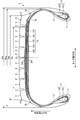
- FIG. 1 is a sectional view in the tire meridian direction showing a pneumatic tire according to an embodiment of the present invention.
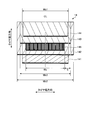
- FIG. 2 is an explanatory view showing a belt layer of the pneumatic tire shown in FIG.
- FIG. 3 is an explanatory view showing a belt layer of the pneumatic tire shown in FIG. 1.
- FIG. 4 is an explanatory diagram illustrating a belt layer of the pneumatic tire illustrated in FIG. 1.
- FIG. 5 is an explanatory view showing a belt layer of the pneumatic tire shown in FIG. 1.
- FIG. 6 is a chart showing the results of the performance test of the pneumatic tire according to the embodiment of the present invention.
- FIG. 7 is a chart showing the results of the performance test of the pneumatic tire according to the embodiment of the present invention.
- FIG. 1 is a sectional view in the tire meridian direction showing a pneumatic tire according to an embodiment of the present invention.
- FIG. 1 shows a heavy-duty radial tire mounted on a truck, a bus, etc. for long-distance transportation.
- Reference sign CL is a tire equator plane.
- the tread end P and the tire ground contact end T coincide.
- the circumferential reinforcing layer 145 is hatched.
- the pneumatic tire 1 includes a pair of bead cores 11, 11, a pair of bead fillers 12, 12, a carcass layer 13, a belt layer 14, a tread rubber 15, and a pair of sidewall rubbers 16, 16. (See FIG. 1).
- the pair of bead cores 11 and 11 has an annular structure and constitutes the core of the left and right bead portions.
- the pair of bead fillers 12 and 12 includes a lower filler 121 and an upper filler 122, which are disposed on the tire radial direction outer periphery of the pair of bead cores 11 and 11, respectively, to reinforce the bead portion.
- the carcass layer 13 is bridged in a toroidal shape between the left and right bead cores 11 and 11 to form a tire skeleton. Further, both ends of the carcass layer 13 are wound and locked from the inner side in the tire width direction to the outer side in the tire width direction so as to wrap the bead core 11 and the bead filler 12.
- the carcass layer 13 is formed by coating a plurality of carcass cords made of steel or an organic fiber material (for example, nylon, polyester, rayon, etc.) with a coating rubber and rolling them, and has an absolute value of 85 [deg] or more and 95. [Deg] The following carcass angle (inclination angle in the fiber direction of the carcass cord with respect to the tire circumferential direction).
- the belt layer 14 is formed by laminating a plurality of belt plies 141 to 145, and is arranged around the outer periphery of the carcass layer 13. A specific configuration of the belt layer 14 will be described later.
- the tread rubber 15 is disposed on the outer circumference in the tire radial direction of the carcass layer 13 and the belt layer 14 to constitute a tread portion of the tire.
- the pair of side wall rubbers 16 and 16 are respectively arranged on the outer side in the tire width direction of the carcass layer 13 to constitute left and right side wall portions.
- the pneumatic tire 1 includes seven circumferential main grooves 2 extending in the tire circumferential direction and eight land portions 3 that are partitioned by these circumferential main grooves 2. I have.
- Each land portion 3 is a block that is divided in the tire circumferential direction by ribs that are continuous in the tire circumferential direction or lug grooves (not shown).
- the circumferential main groove refers to a circumferential groove having a groove width of 5.0 [mm] or more.
- the groove width of the circumferential main groove is measured excluding notches and chamfers formed in the groove openings.
- the left and right circumferential main grooves 2 and 2 on the outermost side in the tire width direction are called outermost circumferential main grooves.
- the left and right land portions 3 and 3 on the outer side in the tire width direction defined by the left and right outermost circumferential main grooves 2 and 2 are referred to as shoulder land portions.
- FIG. 2 and 3 are explanatory views showing a belt layer of the pneumatic tire shown in FIG.
- FIG. 2 shows one side region of the tread portion with the tire equatorial plane CL as a boundary
- FIG. 3 shows a laminated structure of the belt layer 14.
- the thin lines in the belt plies 141 to 145 schematically show the belt cords of the belt plies 141 to 145.
- the belt layer 14 is formed by laminating a high-angle belt 141, a pair of cross belts 142 and 143, a belt cover 144, and a circumferential reinforcing layer 145, and is arranged around the outer periphery of the carcass layer 13. (See FIG. 2).
- the high-angle belt 141 is formed by coating a plurality of belt cords made of steel or organic fiber material with a coat rubber and rolling the belt, and an absolute value of a belt angle of 45 [deg] or more and 70 [deg] or less (tire circumferential direction). The inclination angle of the belt cord in the fiber direction). Further, the high-angle belt 141 is laminated and disposed on the outer side in the tire radial direction of the carcass layer 13.
- the pair of cross belts 142 and 143 is formed by rolling a plurality of belt cords made of steel or organic fiber material covered with a coat rubber, and has an absolute value of a belt angle of 10 [deg] or more and 45 [deg] or less. Have. Further, the pair of cross belts 142 and 143 have belt angles with different signs from each other, and are laminated so that the fiber directions of the belt cords cross each other (cross-ply structure).
- the cross belt 142 located on the inner side in the tire radial direction is called an inner diameter side cross belt
- the cross belt 143 located on the outer side in the tire radial direction is called an outer diameter side cross belt. Note that three or more cross belts may be laminated (not shown). Further, in this embodiment, the pair of cross belts 142 and 143 are stacked on the outer side in the tire radial direction of the high-angle belt 141.
- the belt cover 144 is formed by rolling a plurality of belt cords made of steel or organic fiber material with a coating rubber, and has a belt angle of 10 [deg] or more and 45 [deg] or less in absolute value. Further, the belt cover 144 is disposed so as to be laminated on the outer side in the tire radial direction of the pair of cross belts 142 and 143. In this embodiment, the belt cover 144 has the same belt angle as the outer diameter side crossing belt 143 and is disposed in the outermost layer of the belt layer 14.
- the circumferential reinforcing layer 145 is formed by winding a steel belt cord covered with a coat rubber in a spiral manner while inclining within a range of ⁇ 5 [deg] with respect to the tire circumferential direction. Further, in this embodiment, the circumferential reinforcing layer 145 is disposed between the pair of cross belts 142 and 143. Further, the circumferential reinforcing layer 145 is disposed on the inner side in the tire width direction with respect to the left and right edge portions of the pair of cross belts 142 and 143. Specifically, one or more wires are spirally wound around the outer circumference of the inner diameter side crossing belt 142 to form the circumferential reinforcing layer 145. The circumferential reinforcing layer 145 reinforces the rigidity in the tire circumferential direction, so that the durability performance of the tire is improved.
- the belt layer 14 may have an edge cover (not shown).
- the edge cover is formed by rolling a plurality of belt cords made of steel or organic fiber material with a coating rubber, and has an absolute value of a belt angle of 0 [deg] or more and 5 [deg] or less.
- the edge covers are respectively disposed on the outer sides in the tire radial direction of the left and right edge portions of the outer diameter side cross belt 143 (or the inner diameter side cross belt 142). When these edge covers exhibit a tagging effect, the difference in diameter growth between the center region of the tread portion and the shoulder region is alleviated, and the uneven wear resistance performance of the tire is improved.
- this pneumatic tire 1 employs the following configuration in order to make the outer diameter growth of the tread portion uniform (see FIGS. 1 to 3).
- FIG. 4 and 5 are explanatory views showing a belt layer of the pneumatic tire shown in FIG.
- FIG. 4 shows a laminated structure of the belt plies 141 to 145 on the tire equatorial plane CL
- FIG. 5 shows a laminated structure of the belt plies 141 to 145 at the end of the circumferential reinforcing layer 145. .
- the belt ply laminated on the inner side in the tire radial direction of the circumferential reinforcing layer 145 and adjacent to the circumferential reinforcing layer 145 is referred to as an inner belt ply (inner diameter side cross belt 142 in FIG. 2).
- the belt ply laminated on the outer side in the tire radial direction of the circumferential reinforcing layer 145 and adjacent to the circumferential reinforcing layer 145 is referred to as an outer belt ply (in FIG. 2, the outer diameter side crossing belt 143).
- the inner belt ply and the outer belt ply have a belt angle of 10 [deg] or more and 70 [deg] or less in absolute value.
- the circumferential reinforcing layer 145 is disposed between the pair of cross belts 142 and 143.
- the inner diameter side cross belt 142 is an inner belt ply
- the outer diameter side cross belt 143 is an outer belt ply.
- the inner belt ply and the outer belt ply have a belt angle of 10 [deg] or more and 45 [deg] or less in absolute value, and have mutually different belt angles.
- the invention is not limited to this, and the circumferential reinforcing layer 145 may be disposed on the outer side in the tire radial direction of the pair of cross belts 142 and 143 (not shown). Further, the circumferential reinforcing layer 145 may be disposed inside the pair of cross belts 142 and 143, that is, between the high angle belt 141 and the inner diameter side cross belt 142 (not shown). Also in these cases, the inner belt ply and the outer belt ply are respectively defined according to the positional relationship with the circumferential reinforcing layer 145 described above.
- the inter-cord distance Gcl between the circumferential reinforcing layer 145 and the inner belt ply on the tire equator plane CL, and the cord between the circumferential reinforcing layer 145 and the outer belt ply on the tire equator plane CL. Define the distance Gcu.
- An intercord distance Gsu between the layer 145 and the outer belt ply 143 is defined.
- the inter-cord distances Gcl, Gcu, Gsl, and Gsu are the thicknesses of rubber materials between belt cords in adjacent belt plies, and are measured in a no-load state in which a tire is mounted on a specified rim and filled with a specified internal pressure. . Specifically, for example, a single tire is applied to a virtual line of a tire profile measured by a laser profiler and fixed with a tape or the like.
- the distance in the tire radial direction between the lower end position of the belt cord of the belt ply on the inner side in the tire radial direction and the upper end position of the belt cord of the belt ply on the outer side in the tire radial direction is Etc., and the numerical value is taken as the distance between codes.
- a tire profile measuring device manufactured by Matsuo Corporation
- the end region of the circumferential reinforcing layer 145 is a region from the outer end of the circumferential reinforcing layer 145 in the tire width direction to a position of 20% of the width Ws of the circumferential reinforcing layer 145. They are respectively defined at the left and right ends of the direction reinforcing layer 145.
- the width Ws of the circumferential reinforcing layer 145 is a distance in the tire rotation axis direction between the left and right ends of the circumferential reinforcing layer 145, and is measured as a no-load state while applying a specified internal pressure by attaching the tire to a specified rim.
- the inter-cord distances Gcl, Gcu, Gsl, and Gsu between the circumferential reinforcing layer 145 and the inner belt ply 142 and the outer belt ply 143 satisfy the relationship of 1.20 ⁇ (Gcl + Gcu) / (Gsl + Gsu) ⁇ 9.20. (See FIG. 4 and FIG. 5). That is, the sum of the distances between cords (Gcl + Gcu) between the circumferential reinforcing layer 145 and the inner belt ply 142 and the outer belt ply 143 in the tire equatorial plane CL is the same as the circumferential reinforcing layer 145 in the end region of the circumferential reinforcing layer 145.
- the distance between the inner belt ply 142 and the outer belt ply 143 is set larger than the sum (Gsl + Gsu) of the distance between cords.
- the circumferential reinforcing layer 145 is disposed between the pair of cross belts 142 and 143.
- the inner diameter side cross belt 142 is an inner belt ply
- the outer diameter side cross belt 143 is an outer belt ply.
- a pair of cross belts 142 and 143 are configured by rolling a plurality of belt cords 1421 and 1431 covered with coat rubbers 1422 and 1432.
- the circumferential reinforcing layer 145 is formed by spirally winding a belt cord 1451 covered with a coat rubber 1452 in the tire circumferential direction.
- intermediate rubbers 201 and 202 are disposed between the circumferential reinforcing layer 145 and the inner belt ply 142 and between the circumferential reinforcing layer 145 and the outer belt ply 143, respectively.
- the intermediate rubbers 201 and 202 are made of the same rubber material as the coating rubbers 1452, 1422, and 1432 of the circumferential reinforcing layer 145, the inner belt ply 142, and the outer belt ply 143.
- these intermediate rubbers 201 and 202 have a width narrower than the width Ws of the circumferential reinforcing layer 145 and are arranged in the central region of the circumferential reinforcing layer 145 in the tire width direction.
- these intermediate rubbers 201 and 202 have a thin arc shape in a cross-sectional view in the tire meridian direction, thereby having a maximum gauge on the tire equatorial plane CL and a gauge toward the outer side in the tire width direction. Is gradually reduced. Therefore, as shown in FIG. 4, in the central region of the circumferential reinforcing layer 145 including the tire equatorial plane CL, the sum of the inter-cord distances between the circumferential reinforcing layer 145 and the inner belt ply 142 and the outer belt ply 143 ( Gcl + Gcu) is increased by the intermediate rubbers 201 and 202. Further, as shown in FIG.
- the sum of the distances between the cords inside and outside the circumferential reinforcing layer 145 monotonously decreases from the tire equatorial plane CL toward the end region of the circumferential reinforcing layer 145.
- the sum of the inter-cord distances (Gsl + Gsu) is the tire width. Monotonously decreasing (constant or decreasing) toward the outside in the direction.
- the sum (Gcl + Gcu) of the distance between the cords inside and outside the circumferential reinforcing layer 145 on the tire equatorial plane CL is the distance between the cords inside and outside the circumferential reinforcing layer 145 in the end region of the circumferential reinforcing layer 145. It is set larger than the sum (Gsl + Gsu). Then, the shear stress acting between the belt plies 142, 143, and 145 when the tire rolls is relatively small at the tire equatorial plane CL and relatively large at the end region of the circumferential reinforcing layer 145. . Thereby, the outer diameter growth difference of the tread part between the center part area
- the inter-code distances Gcl, Gcu, Gsl, and Gsu have a relationship of Gsl ⁇ Gcl and Gsu ⁇ Gcu. That is, both the inter-cord distances Gcl and Gsl between the circumferential reinforcing layer 145 and the inner belt ply 142 and the inter-cord distances Gcu and Gsu between the circumferential reinforcing layer 145 and the outer belt ply 143 are related to the tire equatorial plane CL and the circumferential direction. There is a difference in gauge between the end region of the reinforcing layer 145 and the end region. Thereby, the outer diameter growth difference of the tread portion between the central region and the end region of the circumferential reinforcing layer 145 is effectively equalized.
- the present invention is not limited to this, and it is sufficient that the inter-code distances Gcl, Gcu, Gsl, and Gsu satisfy one of the conditions of Gsl ⁇ Gcl and Gsu ⁇ Gcu (not shown). That is, only the inter-cord distances Gcl and Gsl between the circumferential reinforcing layer 145 and the inner belt ply 142, or only the inter-cord distances Gcu and Gsu between the circumferential reinforcing layer 145 and the outer belt ply 143, and the tire equatorial plane CL. There may be a difference in gauge between the end region of the circumferential reinforcing layer 145 and the end region.
- the inter-cord distances Gcl and Gsl between the circumferential reinforcing layer 145 and the inner belt ply 142 have a relationship of Gsl ⁇ Gcl
- the inter-code distances Gcl, Gcu, Gsl, and Gsu are all in the range of 0.10 [mm] or more.
- the upper limit of the inter-cord distances Gcl, Gcu, Gsl, and Gsu is not particularly limited, but is restricted by the specification of the tire and the relationship with the sub-groove gauge of the circumferential main groove 2.
- intermediate rubbers 201 and 202 are used to adjust inter-cord distances Gcl, Gcu, Gsl, and Gsu between the circumferential reinforcing layer 145 and the inner belt ply 142 and the outer belt ply 143. ing.
- Such a configuration is preferable in that the existing circumferential reinforcing layer 145, inner belt ply 142, and outer belt ply 143 having a constant gauge can be employed.
- the present invention is not limited to this, and the distances between cords Gcl, Gcu, Gsl, Gsu are adjusted by adjusting the gauges of the coating rubber 1452 of the circumferential reinforcing layer 145, the coating rubber 1422 of the inner belt ply 142, or the coating rubber 1432 of the outer belt ply 143. May be adjusted.
- the coat rubber 1422 of the inner belt ply 142 or the coat rubber 1432 of the outer belt ply 143 has a large gauge on the tire equatorial plane CL, and gradually decreases the gauge toward the outer side in the tire width direction.
- Gcl, Gcu, Gsl, Gsu can be adjusted. Thereby, the intermediate rubbers 201 and 202 can be omitted.
- the tread width TW and the width Ws of the circumferential reinforcing layer 145 have a relationship of 0.70 ⁇ Ws / TW ⁇ 0.90.
- the tread width TW is the distance between the left and right tread ends P, P in the tire rotation axis direction, and is measured as a no-load state while attaching a tire to a specified rim and applying a specified internal pressure.
- a general pneumatic tire has a bilaterally symmetric structure with the tire equatorial plane CL as the center. For this reason, the distance from the tire equatorial plane CL to the tread end P is TW / 2, and the distance from the tire equatorial plane CL to the circumferential reinforcing layer 145 is Ws / 2.
- the range of the ratio Ws / TW between the tread width TW and the circumferential reinforcing layer width Ws is based on the tire equatorial plane CL. It is regulated by converting to half width. Specifically, the distance TW ′ (not shown) from the tire equatorial plane CL to the tread end P and the distance Ws ′ (not shown) from the tire equatorial plane CL to the end of the circumferential reinforcing layer 145 are 0. .70 ⁇ Ws ′ / TW ′ ⁇ 0.90 is set.
- the tread width TW and the tire total width SW have a relationship of 0.79 ⁇ TW / SW ⁇ 0.89.
- the total tire width SW is the linear distance between the sidewalls (including all parts of the tire side pattern, characters, etc.) when the tire is mounted on the specified rim to provide the specified internal pressure and is in an unloaded state.
- the width Wb2 of the wide cross belt 142 and the cross-sectional width Wca of the carcass layer 13 preferably have a relationship of 0.74 ⁇ Wb2 / Wca ⁇ 0.89, and 0.78 More preferably, it is within the range of ⁇ Wb2 / Wca ⁇ 0.83.
- width Ws of the circumferential reinforcing layer 145 and the cross-sectional width Wca of the carcass layer 13 have a relationship of 0.60 ⁇ Ws / Wca ⁇ 0.70.
- the tread width TW and the cross-sectional width Wca of the carcass layer 13 have a relationship of 0.82 ⁇ TW / Wca ⁇ 0.92.
- the cross-sectional width Wca of the carcass layer 13 refers to a linear distance between the left and right maximum width positions of the carcass layer 13 when a tire is mounted on a specified rim to apply a specified internal pressure and is in an unloaded state.
- the width Wb3 of the narrow cross belt 143 and the width Ws of the circumferential reinforcing layer 145 have a relationship of 0.75 ⁇ Ws / Wb3 ⁇ 0.90. Thereby, the width Ws of the circumferential reinforcing layer 145 is appropriately secured.
- the circumferential reinforcing layer 145 is disposed on the inner side in the tire width direction from the left and right edge portions of the narrow cross belt 143 of the pair of cross belts 142 and 143.
- the width Wb3 of the narrow cross belt 143 and the distance S from the edge portion of the circumferential reinforcing layer 145 to the edge portion of the narrow cross belt 143 are 0.03 ⁇ S / Wb3 ⁇ 0.12. It is preferable that it exists in the range. Thereby, the distance of the edge part of the width Wb3 of the cross belt 143 and the edge part of the circumferential direction reinforcement layer 145 is ensured appropriately.
- the distance S of the circumferential reinforcing layer 145 is measured as a distance in the tire width direction when the tire is mounted on a specified rim to apply a specified internal pressure and is in a no-load state.
- the circumferential reinforcing layer 145 is formed by winding a single steel wire in a spiral shape.
- the present invention is not limited to this, and the circumferential reinforcing layer 145 may be formed by spirally winding a plurality of wires while running parallel to each other (multiple winding structure).
- the number of wires is preferably 5 or less.
- the winding width per unit when multiple windings of five wires are 12 [mm] or less. Thereby, a plurality of wires (2 or more and 5 or less) can be properly wound while being inclined within a range of ⁇ 5 [deg] with respect to the tire circumferential direction.
- the width Wb1 of the high-angle belt 141 and the width Wb3 of the narrower cross belt 143 of the pair of cross belts 142 and 143 are 0.85 ⁇ Wb1 / Wb3 ⁇ 1.05. It is preferable to have the relationship (see FIG. 3). Thereby, the ratio Wb1 / Wb3 is optimized.
- the width Wb1 of the high-angle belt 141 and the width Wb3 of the crossing belt 143 are measured as the distance in the tire width direction when the tire is mounted on the specified rim to apply the specified internal pressure and the load is not loaded.
- the belt layer 14 has a bilaterally symmetric structure centered on the tire equatorial plane CL, and the cross belt is narrower than the width Wb ⁇ b> 1 of the high-angle belt 141.
- the width Wb3 of 143 has a relationship of Wb1 ⁇ Wb3.
- the edge part of the high angle belt 141 is arrange
- the present invention is not limited to this, and the width Wb1 of the high-angle belt 141 and the width Wb3 of the narrow cross belt 143 may have a relationship of Wb1 ⁇ Wb3 (not shown).
- the belt cord of the high-angle belt 141 is a steel wire and the high-angle belt has an end number of 15 [lines / 50 mm] or more and 25 [lines / 50 mm] or less.
- the belt cords of the pair of cross belts 142 and 143 are preferably steel wires, and the pair of cross belts 142 and 143 preferably have an end number of 18 [lines / 50 mm] or more and 28 [lines / 50 mm] or less. It is more preferable to have an end number of [lines / 50 mm] or more and 25 [lines / 50 mm] or less.
- the belt cord of the circumferential reinforcing layer 145 is preferably a steel wire and has an end number of 17 [pieces / 50 mm] or more and 30 [pieces / 50 mm] or less. Thereby, the strength of each belt ply 141, 142, 143, 145 is ensured appropriately.
- the modulus E1 when the coated rubber of the high-angle belt 141 is 100% stretched and the modulus Es when the coated rubber of the circumferential reinforcing layer 145 is stretched 100% have a relationship of 0.90 ⁇ Es / E1 ⁇ 1.10. Is preferred.
- the modulus E2 and E3 when the coat rubber of the pair of cross belts 142 and 143 is 100% stretched and the modulus Es when the coat rubber of the circumferential reinforcing layer 145 is 100% stretched are 0.90 ⁇ Es / E2 ⁇ 1.10. And it is preferable to have a relationship of 0.90 ⁇ Es / E3 ⁇ 1.10.
- the modulus Es when the coated rubber of the circumferential reinforcing layer 145 is 100% stretched is preferably in the range of 4.5 [MPa] ⁇ Es ⁇ 7.5 [MPa]. Thereby, the modulus of each belt ply 141, 142, 143, 145 is optimized.
- the modulus at 100% elongation is measured by a tensile test at room temperature according to JIS-K6251 (using No. 3 dumbbell).
- the breaking elongation ⁇ 1 of the coated rubber of the high-angle belt 141 is preferably in the range of ⁇ 1 ⁇ 200 [%]. Further, it is preferable that the breaking elongations ⁇ 2 and ⁇ 3 of the coat rubber of the pair of cross belts 142 and 143 are in the range of ⁇ 2 ⁇ 200 [%] and ⁇ 3 ⁇ 200 [%]. In addition, the elongation at break ⁇ s of the coated rubber of the circumferential reinforcing layer 145 is preferably in the range of ⁇ s ⁇ 200 [%]. Thereby, durability of each belt ply 141, 142, 143, 145 is ensured appropriately.
- Elongation at break is 2 [mm] using a tensile tester (INSTRON 5585H, manufactured by Instron) in accordance with JIS-K7161 for test pieces of JIS-K7162 standard type 1B (dumbbell type with a thickness of 3 mm). / Min].
- the elongation at a tensile load of 100 [N] to 300 [N] is 1.0 [%] or more and 2.5 [%] or less.
- the elongation at a tensile load of 500 [N] to 1000 [N] is preferably 0.5 [%] or more and 2.0 [%] or less.
- Such a belt cord (high elongation steel wire) has a better elongation at low load than normal steel wire, and can withstand the load applied to the circumferential reinforcing layer 145 from the time of manufacture to the time of tire use. This is preferable in that damage to the circumferential reinforcing layer 145 can be suppressed.
- the elongation of the belt cord is measured according to JIS-G3510.
- the elongation at break of the tread rubber 15 is in a range of 350 [%] or more. Thereby, the strength of the tread rubber 15 is ensured, and the occurrence of tears in the outermost circumferential main groove 2 is suppressed.
- the upper limit of the elongation at break of the tread rubber 15 is not particularly limited, but is restricted by the type of rubber compound of the tread rubber 15.
- the tread rubber 15 preferably has a hardness of 60 or more. Thereby, the strength of the tread rubber 15 is ensured appropriately.
- the upper limit of the hardness of the tread rubber 15 is not particularly limited, but is restricted by the type of rubber compound of the tread rubber 15.
- Rubber hardness means JIS-A hardness according to JIS-K6263.
- the loss tangent tan ⁇ of the tread rubber 15 is preferably in the range of 0.10 ⁇ tan ⁇ .
- the loss tangent tan ⁇ is measured using a viscoelastic spectrometer under conditions of a temperature of 20 [° C.], a shear strain of 10 [%], and a frequency of 20 [Hz].
- the circumferential reinforcing layer 145 is disposed on the inner side in the tire width direction from the left and right edge portions of the narrow cross belt 143 of the pair of cross belts 142 and 143. Further, the belt edge cushion 19 is sandwiched and disposed at a position between the pair of cross belts 142 and 143 and corresponding to the edge portions of the pair of cross belts 142 and 143.
- the belt edge cushion 19 is disposed on the outer side in the tire width direction of the circumferential reinforcing layer 145 and is adjacent to the circumferential reinforcing layer 145, and a pair of ends from the outer end of the circumferential reinforcing layer 145 in the tire width direction.
- the cross belts 142 and 143 are arranged so as to extend to the outer ends in the tire width direction.
- the belt edge cushion 19 has a structure thicker than the circumferential reinforcing layer 145 as a whole by increasing the thickness toward the outer side in the tire width direction. .
- the belt edge cushion 19 has a modulus E at 100% extension lower than the coat rubber of each cross belt 142, 143.
- the modulus E at 100% extension of the belt edge cushion 19 and the modulus Eco of the coat rubber have a relationship of 0.60 ⁇ E / Eco ⁇ 0.95.
- the modulus E at the time of 100% extension of the belt edge cushion 19 is in the range of 4.0 [MPa] ⁇ E ⁇ 5.5 [MPa].
- the pneumatic tire 1 includes the carcass layer 13, the belt layer 14 disposed outside the carcass layer 13 in the tire radial direction, and the tread rubber 15 disposed outside the belt layer 14 in the tire radial direction. (See FIG. 1 and FIG. 2).
- the belt layer 14 has a circumferential reinforcing layer 145 having a belt angle within a range of ⁇ 5 [deg] with respect to the tire circumferential direction, and a belt angle of 10 [deg] to 70 [deg] in absolute value.
- an inner belt ply inner diameter side cross belt 142 in FIG. 2
- an outer belt ply in FIG.
- an outer diameter side crossing belt 143) is provided. Further, a cord distance Gcl between the circumferential reinforcing layer 145 and the inner belt ply 142 on the tire equator plane CL, a cord distance Gcu between the circumferential reinforcing layer 145 and the outer belt ply 143 on the tire equator plane CL, and a circumferential reinforcing layer.
- the inter-cord distance Gsl between the circumferential reinforcing layer 145 and the inner belt ply 142 in the end region of 145, and the inter-cord distance between the circumferential reinforcing layer 145 and the outer belt ply 143 in the end region of the circumferential reinforcing layer 145 Gsu has a relationship of 1.20 ⁇ (Gcl + Gcu) / (Gsl + Gsu) ⁇ 9.20 (see FIGS. 4 and 5).
- the sum of the distances between the cords inside and outside the circumferential reinforcing layer 145 on the tire equatorial plane CL (Gcl + Gcu) is the sum of the distances between the cords inside and outside the circumferential reinforcing layer 145 in the end region of the circumferential reinforcing layer 145. It is set larger than (Gsl + Gsu). Then, the shear stress acting between the belt plies 142, 143, and 145 when the tire rolls is relatively small at the tire equatorial plane CL and relatively large at the end region of the circumferential reinforcing layer 145. .
- region of the circumferential direction reinforcement layer 145 is equalized, and there exists an advantage which the outer diameter uniform growth performance of a tire improves. That is, when 1.20 ⁇ (Gcl + Gcu) / (Gsl + Gsu), the diameter growth of the shoulder region of the tread portion is effectively suppressed, and when (Gcl + Gcu) / (Gsl + Gsu) ⁇ 9.20, the tread portion The diameter growth of the center region is effectively suppressed.
- the width Ws of the circumferential reinforcing layer 145 and the cross-sectional width Wca of the carcass layer 13 have a relationship of 0.60 ⁇ Ws / Wca ⁇ 0.70 (see FIG. 1).
- the ratio Ws / Wca between the width Ws of the circumferential reinforcing layer 145 and the width Wca of the carcass layer 13 is optimized. That is, by satisfying 0.60 ⁇ Ws / Wca, the tire diameter growth suppressing function (tagged effect) by the circumferential reinforcing layer 145 is appropriately ensured. Further, when Ws / Wca ⁇ 0.70, fatigue rupture of the belt cord at the edge portion of the circumferential reinforcing layer 145 is suppressed.
- the inter-cord distances Gcl, Gcu, Gsl, and Gsu are all in the range of 0.10 [mm] or more.
- the inter-cord distances Gcl, Gcu, Gsl, and Gsu are appropriately secured, and the distortion of the rubber material between the belt plies 142, 143, and 145 is reduced.
- the cross-sectional width Wca of the carcass layer 13 and the width Wb2 of the inner belt ply 142 have a relationship of 0.74 ⁇ Wb2 / Wca ⁇ 0.89 (see FIG. 1).
- the width Wb2 of the inner belt ply 142 is optimized, and there is an advantage that the durability performance of the tire is improved.
- the width Wb3 of the outer belt ply 143 and the width Ws of the circumferential reinforcing layer 145 have a relationship of 0.75 ⁇ Ws / Wb3 ⁇ 0.90. Thereby, the width Ws of the circumferential reinforcing layer 145 is optimized, and there is an advantage that the durability performance of the tire is improved.
- the inner belt ply and the outer belt ply each have a belt angle of 15 [deg] or more and 60 [deg] or less in absolute value.
- the belt angle of the belt ply adjacent to the circumferential reinforcing layer is optimized, and there is an advantage that the durability performance and steering stability performance of the tire are improved.
- the diameters of the belt cords 1451, 1421, and 1431 of the circumferential reinforcing layer 145, the inner belt ply 142, and the outer belt ply 143 are 1.20 [mm] or more and 2.20 [mm], respectively.
- the difference in rigidity between the belt plies 145, 142, and 143 can be reduced, there is an advantage that the durability performance of the tire is improved.
- the number of ends of the belt cords 1451, 1421, and 1431 of the circumferential reinforcing layer 145, the inner belt ply 142, and the outer belt ply 143 is 18 [lines / 50mm] or more and 28 [lines / 50mm]. It is in the following range. Thereby, since the difference in rigidity between the belt plies 145, 142, and 143 can be reduced, there is an advantage that the durability performance of the tire is improved.
- the inter-cord distances Gcl, Gcu, Gsl, and Gsu have a relationship of Gsl ⁇ Gcl and Gsu ⁇ Gcu.
- the inter-cord distances Gcl and Gsl between the circumferential reinforcing layer 145 and the inner belt ply 142 and the inter-cord distances Gcu and Gsu between the circumferential reinforcing layer 145 and the outer belt ply 143 are both determined from the tire equatorial plane CL. Since there is a gauge difference between the end region of the circumferential reinforcing layer 145 and the outer diameter growth difference of the tread portion between the central region and the end region of the circumferential reinforcing layer 145 is effectively equalized. There are advantages.
- the sum of the inter-cord distances Gsl and Gsu monotonously decreases (constant or decreases) toward the outer side in the tire width direction in the end region of the circumferential reinforcing layer 145 (FIG. 2).
- the shear stress acting between the belt plies 142, 143, and 145 in the end region of the circumferential reinforcing layer 145 becomes relatively large, and there is an advantage that the diameter growth of the tread shoulder region is effectively suppressed. .
- the inner belt ply 142 and the outer belt ply 143 have a belt angle of 10 [deg] or more and 45 [deg] or less in absolute value, and have mutually different belt angles. (See FIG. 3). Thereby, there exists an advantage which the durable performance of a tire improves.
- the tread width TW and the tire total width SW have a relationship of 0.79 ⁇ TW / SW ⁇ 0.89 (see FIG. 1).
- the ratio TW / SW is within the above range, the radial growth of the left and right shoulder portions is suppressed. Then, the diameter growth difference between the center region and the shoulder region is relaxed, and the contact pressure distribution of the tire is made uniform. Thereby, there is an advantage that the uneven wear resistance of the tire is improved. Specifically, when 0.79 ⁇ TW / SW, the average contact pressure decreases. Further, when TW / SW ⁇ 0.89, the rise of the shoulder portion is suppressed, and the bending at the time of the ground contact shape is suppressed.
- the tread width TW and the cross-sectional width Wca of the carcass layer 13 have a relationship of 0.82 ⁇ TW / Wca ⁇ 0.92 (see FIG. 1).
- the belt layer 14 includes the circumferential reinforcing layer 145, thereby suppressing the radial growth of the center region.
- the ratio TW / Wca is within the above range, the difference in diameter growth between the center region and the shoulder region is alleviated, and the contact pressure distribution in the tire width direction is made uniform. Thereby, there exists an advantage by which the contact pressure distribution of a tire is equalized.
- 6 and 7 are charts showing the results of the performance test of the pneumatic tire according to the embodiment of the present invention.
- the outer diameter change amount of the center area of the tread portion and the outer diameter change of the shoulder area when the filling inner pressure of the test tire is increased from 100 [kPa] to 900 [kPa].
- the quantity is measured.
- the ratio outer diameter change amount of the shoulder region / outer diameter change amount of the center region
- index evaluation is performed. In this evaluation, if the numerical value is in the range of 95 or more and 105 or less, it can be said that the uniform outer diameter growth performance of the tire is appropriately secured.
- the test tire is filled with an internal pressure of 900 [kPa].
- a low-pressure durability test using an indoor drum tester is performed. The running speed was set to 45 [km / h], and the load was increased by 5 [%] (1.74 [kN]) every 12 hours from the load 34.81 [kN], and the tire broke down. The distance traveled is measured. Then, based on this measurement result, index evaluation using the conventional example as a reference (100) is performed. This evaluation is preferable as the numerical value increases.
Landscapes
- Engineering & Computer Science (AREA)
- Mechanical Engineering (AREA)
- Tires In General (AREA)
Abstract
Description
図1は、この発明の実施の形態にかかる空気入りタイヤを示すタイヤ子午線方向の断面図である。同図は、空気入りタイヤ1の一例として、長距離輸送用のトラック、バスなどに装着される重荷重用ラジアルタイヤを示している。なお、符号CLは、タイヤ赤道面である。また、同図では、トレッド端Pとタイヤ接地端Tとが、一致している。また、同図では、周方向補強層145にハッチングを付してある。
図2および図3は、図1に記載した空気入りタイヤのベルト層を示す説明図である。これらの図において、図2は、タイヤ赤道面CLを境界としたトレッド部の片側領域を示し、図3は、ベルト層14の積層構造を示している。なお、図3では、各ベルトプライ141~145中の細線が各ベルトプライ141~145のベルトコードを模式的に示している。
トラック・バスなどに装着される近年の重荷重用タイヤは、低い偏平率を有する一方で、ベルト層に周方向補強層を配置することにより、トレッド部の形状を保持している。具体的には、周方向補強層が、トレッド部センター領域に配置されてタガ効果を発揮することにより、トレッド部の外径成長を抑制してトレッド部の形状を保持している。
また、この空気入りタイヤ1では、図1において、トレッド幅TWと、周方向補強層145の幅Wsとが、0.70≦Ws/TW≦0.90の関係を有することが好ましい。
図1および図2の構成では、周方向補強層145が、一対の交差ベルト142、143のうち幅狭な交差ベルト143の左右のエッジ部よりもタイヤ幅方向内側に配置されている。また、一対の交差ベルト142、143の間であって一対の交差ベルト142、143のエッジ部に対応する位置に、ベルトエッジクッション19が挟み込まれて配置されている。具体的には、ベルトエッジクッション19が、周方向補強層145のタイヤ幅方向外側に配置されて周方向補強層145に隣接し、周方向補強層145のタイヤ幅方向外側の端部から一対の交差ベルト142、143のタイヤ幅方向外側の端部まで延在して配置されている。
以上説明したように、この空気入りタイヤ1は、カーカス層13と、カーカス層13のタイヤ径方向外側に配置されるベルト層14と、ベルト層14のタイヤ径方向外側に配置されるトレッドゴム15とを備える(図1および図2参照)。また、ベルト層14が、タイヤ周方向に対して±5[deg]の範囲内にあるベルト角度を有する周方向補強層145と、絶対値で10[deg]以上70[deg]以下のベルト角度を有すると共に周方向補強層145のタイヤ径方向内側およびタイヤ径方向外側にそれぞれ積層されて周方向補強層145に隣接する内側ベルトプライ(図2では、内径側交差ベルト142)および外側ベルトプライ(図2では、外径側交差ベルト143)とを備える。また、タイヤ赤道面CLにおける周方向補強層145と内側ベルトプライ142とのコード間距離Gcl、タイヤ赤道面CLにおける周方向補強層145と外側ベルトプライ143とのコード間距離Gcu、周方向補強層145の端部領域における周方向補強層145と内側ベルトプライ142とのコード間距離Gsl、および、周方向補強層145の端部領域における周方向補強層145と外側ベルトプライ143とのコード間距離Gsuが、1.20≦(Gcl+Gcu)/(Gsl+Gsu)≦9.20の関係を有する(図4および図5参照)。
Claims (13)
- カーカス層と、前記カーカス層のタイヤ径方向外側に配置されるベルト層と、前記ベルト層のタイヤ径方向外側に配置されるトレッドゴムとを備える空気入りタイヤであって、
前記ベルト層が、タイヤ周方向に対して±5[deg]の範囲内にあるベルト角度を有する周方向補強層と、絶対値で10[deg]以上70[deg]以下のベルト角度を有すると共に前記周方向補強層のタイヤ径方向内側およびタイヤ径方向外側にそれぞれ積層されて前記周方向補強層に隣接する内側ベルトプライおよび外側ベルトプライとを備え、且つ、
タイヤ赤道面における前記周方向補強層と前記内側ベルトプライとのコード間距離Gcl、タイヤ赤道面における前記周方向補強層と前記外側ベルトプライとのコード間距離Gcu、前記周方向補強層の端部領域における前記周方向補強層と前記内側ベルトプライとのコード間距離Gsl、および、前記周方向補強層の端部領域における前記周方向補強層と前記外側ベルトプライとのコード間距離Gsuが、1.20≦(Gcl+Gcu)/(Gsl+Gsu)≦9.20の関係を有することを特徴とする空気入りタイヤ。 - 前記周方向補強層の幅Wsと、前記カーカス層の断面幅Wcaとが、0.60≦Ws/Wca≦0.70の関係を有する請求項1に記載の空気入りタイヤ。
- コード間距離Gcl、Gcu、Gsl、Gsuが、いずれも0.10[mm]以上の範囲にある請求項1または2に記載の空気入りタイヤ。
- 前記カーカス層の断面幅Wcaと、前記内側ベルトプライの幅Wb2とが、0.74≦Wb2/Wca≦0.89の関係を有する請求項1~3のいずれか一つに記載の空気入りタイヤ。
- 前記外側ベルトプライの幅Wb3と、前記周方向補強層の幅Wsとが、0.75≦Ws/Wb3≦0.90の関係を有する請求項1~4のいずれか一つに記載の空気入りタイヤ。
- 前記内側ベルトプライおよび前記外側ベルトプライが、絶対値で15[deg]以上60[deg]以下のベルト角度をそれぞれ有する請求項1~5のいずれか一つに記載の空気入りタイヤ。
- 前記周方向補強層、前記内側ベルトプライおよび前記外側ベルトプライのベルトコードの径が、それぞれ1.20[mm]以上2.20[mm]以下の範囲内にある請求項1~6のいずれか一つに記載の空気入りタイヤ。
- 前記周方向補強層、前記内側ベルトプライおよび前記外側ベルトプライのベルトコードのエンド数が、18[本/50mm]以上28[本/50mm]以下の範囲にある請求項1~7のいずれか一つに記載の空気入りタイヤ。
- コード間距離Gcl、Gcu、Gsl、Gsuが、Gsl<GclかつGsu<Gcuの関係を有する請求項1~8のいずれか一つに記載の空気入りタイヤ。
- コード間距離Gsl、Gsuの和(Gsl+Gsu)が、前記周方向補強層の端部領域にてタイヤ幅方向外側に向かって単調減少する請求項1~9のいずれか一つに記載の空気入りタイヤ。
- 前記内側ベルトプライおよび前記外側ベルトプライが、絶対値で10[deg]以上45[deg]以下のベルト角度を有すると共に相互に異符号のベルト角度を有する交差ベルトである請求項1~10のいずれか一つに記載の空気入りタイヤ。
- トレッド幅TWと、タイヤ総幅SWとが、0.79≦TW/SW≦0.89の関係を有する請求項1~11のいずれか一つに記載の空気入りタイヤ。
- トレッド幅TWと、前記カーカス層の断面幅Wcaとが、0.82≦TW/Wca≦0.92の関係を有する請求項1~12のいずれか一つに記載の空気入りタイヤ。
Priority Applications (4)
| Application Number | Priority Date | Filing Date | Title |
|---|---|---|---|
| CN201480021211.1A CN105121182B (zh) | 2013-04-23 | 2014-04-22 | 充气轮胎 |
| US14/786,529 US10377179B2 (en) | 2013-04-23 | 2014-04-22 | Pneumatic tire |
| DE112014002101.6T DE112014002101B4 (de) | 2013-04-23 | 2014-04-22 | Luftreifen |
| KR1020157015090A KR101729144B1 (ko) | 2013-04-23 | 2014-04-22 | 공기입 타이어 |
Applications Claiming Priority (2)
| Application Number | Priority Date | Filing Date | Title |
|---|---|---|---|
| JP2013090697A JP5831491B2 (ja) | 2013-04-23 | 2013-04-23 | 空気入りタイヤ |
| JP2013-090697 | 2013-04-23 |
Publications (1)
| Publication Number | Publication Date |
|---|---|
| WO2014175286A1 true WO2014175286A1 (ja) | 2014-10-30 |
Family
ID=51791857
Family Applications (1)
| Application Number | Title | Priority Date | Filing Date |
|---|---|---|---|
| PCT/JP2014/061332 Ceased WO2014175286A1 (ja) | 2013-04-23 | 2014-04-22 | 空気入りタイヤ |
Country Status (6)
| Country | Link |
|---|---|
| US (1) | US10377179B2 (ja) |
| JP (1) | JP5831491B2 (ja) |
| KR (1) | KR101729144B1 (ja) |
| CN (1) | CN105121182B (ja) |
| DE (1) | DE112014002101B4 (ja) |
| WO (1) | WO2014175286A1 (ja) |
Cited By (1)
| Publication number | Priority date | Publication date | Assignee | Title |
|---|---|---|---|---|
| US11014409B2 (en) | 2015-10-06 | 2021-05-25 | The Yokohama Rubber Co., Ltd. | Pneumatic tire |
Families Citing this family (3)
| Publication number | Priority date | Publication date | Assignee | Title |
|---|---|---|---|---|
| JP6720539B2 (ja) * | 2016-01-13 | 2020-07-08 | 住友ゴム工業株式会社 | 空気入りタイヤ |
| JP6860712B2 (ja) * | 2020-01-29 | 2021-04-21 | 株式会社ブリヂストン | 重荷重用空気入りタイヤ |
| DE102021205282A1 (de) * | 2021-05-25 | 2022-12-01 | Continental Reifen Deutschland Gmbh | Fahrzeugluftreifen mit einer Bandage |
Citations (3)
| Publication number | Priority date | Publication date | Assignee | Title |
|---|---|---|---|---|
| JPH06171309A (ja) * | 1992-12-11 | 1994-06-21 | Sumitomo Rubber Ind Ltd | 重荷重用タイヤ |
| WO2013031021A1 (ja) * | 2011-09-02 | 2013-03-07 | 横浜ゴム株式会社 | 空気入りタイヤ |
| JP5182454B1 (ja) * | 2012-07-13 | 2013-04-17 | 横浜ゴム株式会社 | 空気入りタイヤ |
Family Cites Families (3)
| Publication number | Priority date | Publication date | Assignee | Title |
|---|---|---|---|---|
| JPS5182454A (ja) | 1975-01-16 | 1976-07-20 | Masami Matsuki | Hyomenekishushuki |
| JP2009255619A (ja) * | 2008-04-11 | 2009-11-05 | Bridgestone Corp | 空気入りタイヤ |
| JP5527003B2 (ja) * | 2010-05-11 | 2014-06-18 | 横浜ゴム株式会社 | 空気入りタイヤ |
-
2013
- 2013-04-23 JP JP2013090697A patent/JP5831491B2/ja active Active
-
2014
- 2014-04-22 CN CN201480021211.1A patent/CN105121182B/zh active Active
- 2014-04-22 DE DE112014002101.6T patent/DE112014002101B4/de active Active
- 2014-04-22 WO PCT/JP2014/061332 patent/WO2014175286A1/ja not_active Ceased
- 2014-04-22 KR KR1020157015090A patent/KR101729144B1/ko active Active
- 2014-04-22 US US14/786,529 patent/US10377179B2/en active Active
Patent Citations (3)
| Publication number | Priority date | Publication date | Assignee | Title |
|---|---|---|---|---|
| JPH06171309A (ja) * | 1992-12-11 | 1994-06-21 | Sumitomo Rubber Ind Ltd | 重荷重用タイヤ |
| WO2013031021A1 (ja) * | 2011-09-02 | 2013-03-07 | 横浜ゴム株式会社 | 空気入りタイヤ |
| JP5182454B1 (ja) * | 2012-07-13 | 2013-04-17 | 横浜ゴム株式会社 | 空気入りタイヤ |
Cited By (1)
| Publication number | Priority date | Publication date | Assignee | Title |
|---|---|---|---|---|
| US11014409B2 (en) | 2015-10-06 | 2021-05-25 | The Yokohama Rubber Co., Ltd. | Pneumatic tire |
Also Published As
| Publication number | Publication date |
|---|---|
| DE112014002101T5 (de) | 2015-12-31 |
| KR20150083118A (ko) | 2015-07-16 |
| US10377179B2 (en) | 2019-08-13 |
| CN105121182B (zh) | 2017-04-19 |
| US20160068018A1 (en) | 2016-03-10 |
| DE112014002101B4 (de) | 2022-02-03 |
| CN105121182A (zh) | 2015-12-02 |
| JP2014213648A (ja) | 2014-11-17 |
| KR101729144B1 (ko) | 2017-04-21 |
| JP5831491B2 (ja) | 2015-12-09 |
Similar Documents
| Publication | Publication Date | Title |
|---|---|---|
| JP6299216B2 (ja) | 空気入りタイヤ | |
| JP5182453B1 (ja) | 空気入りタイヤ | |
| US10166819B2 (en) | Pneumatic tire | |
| JP5974896B2 (ja) | 空気入りタイヤ | |
| WO2014010092A1 (ja) | 空気入りタイヤ | |
| JPWO2014103069A1 (ja) | 空気入りタイヤ | |
| JP6079622B2 (ja) | 空気入りタイヤ | |
| JP6015450B2 (ja) | 空気入りタイヤ | |
| JP6079237B2 (ja) | 空気入りタイヤ | |
| JP5831491B2 (ja) | 空気入りタイヤ | |
| WO2014103062A1 (ja) | 空気入りタイヤ | |
| JP6107649B2 (ja) | 空気入りタイヤ |
Legal Events
| Date | Code | Title | Description |
|---|---|---|---|
| WWE | Wipo information: entry into national phase |
Ref document number: 201480021211.1 Country of ref document: CN |
|
| 121 | Ep: the epo has been informed by wipo that ep was designated in this application |
Ref document number: 14788885 Country of ref document: EP Kind code of ref document: A1 |
|
| ENP | Entry into the national phase |
Ref document number: 20157015090 Country of ref document: KR Kind code of ref document: A |
|
| WWE | Wipo information: entry into national phase |
Ref document number: 14786529 Country of ref document: US |
|
| WWE | Wipo information: entry into national phase |
Ref document number: 1120140021016 Country of ref document: DE Ref document number: 112014002101 Country of ref document: DE |
|
| 122 | Ep: pct application non-entry in european phase |
Ref document number: 14788885 Country of ref document: EP Kind code of ref document: A1 |