WO2014174702A1 - 特徴量算出装置、特徴量算出方法および記録媒体 - Google Patents
特徴量算出装置、特徴量算出方法および記録媒体 Download PDFInfo
- Publication number
- WO2014174702A1 WO2014174702A1 PCT/JP2013/076641 JP2013076641W WO2014174702A1 WO 2014174702 A1 WO2014174702 A1 WO 2014174702A1 JP 2013076641 W JP2013076641 W JP 2013076641W WO 2014174702 A1 WO2014174702 A1 WO 2014174702A1
- Authority
- WO
- WIPO (PCT)
- Prior art keywords
- unit
- signal
- feature amount
- doppler
- amount calculation
- Prior art date
- Legal status (The legal status is an assumption and is not a legal conclusion. Google has not performed a legal analysis and makes no representation as to the accuracy of the status listed.)
- Ceased
Links
Images



Classifications
-
- A—HUMAN NECESSITIES
- A61—MEDICAL OR VETERINARY SCIENCE; HYGIENE
- A61B—DIAGNOSIS; SURGERY; IDENTIFICATION
- A61B8/00—Diagnosis using ultrasonic, sonic or infrasonic waves
- A61B8/48—Diagnostic techniques
- A61B8/488—Diagnostic techniques involving Doppler signals
-
- A—HUMAN NECESSITIES
- A61—MEDICAL OR VETERINARY SCIENCE; HYGIENE
- A61B—DIAGNOSIS; SURGERY; IDENTIFICATION
- A61B8/00—Diagnosis using ultrasonic, sonic or infrasonic waves
- A61B8/52—Devices using data or image processing specially adapted for diagnosis using ultrasonic, sonic or infrasonic waves
- A61B8/5215—Devices using data or image processing specially adapted for diagnosis using ultrasonic, sonic or infrasonic waves involving processing of medical diagnostic data
- A61B8/5223—Devices using data or image processing specially adapted for diagnosis using ultrasonic, sonic or infrasonic waves involving processing of medical diagnostic data for extracting a diagnostic or physiological parameter from medical diagnostic data
-
- G—PHYSICS
- G01—MEASURING; TESTING
- G01S—RADIO DIRECTION-FINDING; RADIO NAVIGATION; DETERMINING DISTANCE OR VELOCITY BY USE OF RADIO WAVES; LOCATING OR PRESENCE-DETECTING BY USE OF THE REFLECTION OR RERADIATION OF RADIO WAVES; ANALOGOUS ARRANGEMENTS USING OTHER WAVES
- G01S13/00—Systems using the reflection or reradiation of radio waves, e.g. radar systems; Analogous systems using reflection or reradiation of waves whose nature or wavelength is irrelevant or unspecified
- G01S13/02—Systems using reflection of radio waves, e.g. primary radar systems; Analogous systems
- G01S13/50—Systems of measurement based on relative movement of target
- G01S13/52—Discriminating between fixed and moving objects or between objects moving at different speeds
- G01S13/56—Discriminating between fixed and moving objects or between objects moving at different speeds for presence detection
-
- G—PHYSICS
- G01—MEASURING; TESTING
- G01S—RADIO DIRECTION-FINDING; RADIO NAVIGATION; DETERMINING DISTANCE OR VELOCITY BY USE OF RADIO WAVES; LOCATING OR PRESENCE-DETECTING BY USE OF THE REFLECTION OR RERADIATION OF RADIO WAVES; ANALOGOUS ARRANGEMENTS USING OTHER WAVES
- G01S15/00—Systems using the reflection or reradiation of acoustic waves, e.g. sonar systems
- G01S15/02—Systems using the reflection or reradiation of acoustic waves, e.g. sonar systems using reflection of acoustic waves
- G01S15/50—Systems of measurement, based on relative movement of the target
- G01S15/52—Discriminating between fixed and moving objects or between objects moving at different speeds
- G01S15/523—Discriminating between fixed and moving objects or between objects moving at different speeds for presence detection
-
- G—PHYSICS
- G01—MEASURING; TESTING
- G01S—RADIO DIRECTION-FINDING; RADIO NAVIGATION; DETERMINING DISTANCE OR VELOCITY BY USE OF RADIO WAVES; LOCATING OR PRESENCE-DETECTING BY USE OF THE REFLECTION OR RERADIATION OF RADIO WAVES; ANALOGOUS ARRANGEMENTS USING OTHER WAVES
- G01S15/00—Systems using the reflection or reradiation of acoustic waves, e.g. sonar systems
- G01S15/02—Systems using the reflection or reradiation of acoustic waves, e.g. sonar systems using reflection of acoustic waves
- G01S15/50—Systems of measurement, based on relative movement of the target
- G01S15/58—Velocity or trajectory determination systems; Sense-of-movement determination systems
-
- G—PHYSICS
- G01—MEASURING; TESTING
- G01S—RADIO DIRECTION-FINDING; RADIO NAVIGATION; DETERMINING DISTANCE OR VELOCITY BY USE OF RADIO WAVES; LOCATING OR PRESENCE-DETECTING BY USE OF THE REFLECTION OR RERADIATION OF RADIO WAVES; ANALOGOUS ARRANGEMENTS USING OTHER WAVES
- G01S15/00—Systems using the reflection or reradiation of acoustic waves, e.g. sonar systems
- G01S15/88—Sonar systems specially adapted for specific applications
-
- G—PHYSICS
- G01—MEASURING; TESTING
- G01S—RADIO DIRECTION-FINDING; RADIO NAVIGATION; DETERMINING DISTANCE OR VELOCITY BY USE OF RADIO WAVES; LOCATING OR PRESENCE-DETECTING BY USE OF THE REFLECTION OR RERADIATION OF RADIO WAVES; ANALOGOUS ARRANGEMENTS USING OTHER WAVES
- G01S17/00—Systems using the reflection or reradiation of electromagnetic waves other than radio waves, e.g. lidar systems
- G01S17/02—Systems using the reflection of electromagnetic waves other than radio waves
- G01S17/50—Systems of measurement based on relative movement of target
- G01S17/58—Velocity or trajectory determination systems; Sense-of-movement determination systems
-
- G—PHYSICS
- G01—MEASURING; TESTING
- G01S—RADIO DIRECTION-FINDING; RADIO NAVIGATION; DETERMINING DISTANCE OR VELOCITY BY USE OF RADIO WAVES; LOCATING OR PRESENCE-DETECTING BY USE OF THE REFLECTION OR RERADIATION OF RADIO WAVES; ANALOGOUS ARRANGEMENTS USING OTHER WAVES
- G01S17/00—Systems using the reflection or reradiation of electromagnetic waves other than radio waves, e.g. lidar systems
- G01S17/88—Lidar systems specially adapted for specific applications
-
- G—PHYSICS
- G01—MEASURING; TESTING
- G01S—RADIO DIRECTION-FINDING; RADIO NAVIGATION; DETERMINING DISTANCE OR VELOCITY BY USE OF RADIO WAVES; LOCATING OR PRESENCE-DETECTING BY USE OF THE REFLECTION OR RERADIATION OF RADIO WAVES; ANALOGOUS ARRANGEMENTS USING OTHER WAVES
- G01S7/00—Details of systems according to groups G01S13/00, G01S15/00, G01S17/00
- G01S7/48—Details of systems according to groups G01S13/00, G01S15/00, G01S17/00 of systems according to group G01S17/00
- G01S7/4802—Details of systems according to groups G01S13/00, G01S15/00, G01S17/00 of systems according to group G01S17/00 using analysis of echo signal for target characterisation; Target signature; Target cross-section
-
- G—PHYSICS
- G01—MEASURING; TESTING
- G01S—RADIO DIRECTION-FINDING; RADIO NAVIGATION; DETERMINING DISTANCE OR VELOCITY BY USE OF RADIO WAVES; LOCATING OR PRESENCE-DETECTING BY USE OF THE REFLECTION OR RERADIATION OF RADIO WAVES; ANALOGOUS ARRANGEMENTS USING OTHER WAVES
- G01S7/00—Details of systems according to groups G01S13/00, G01S15/00, G01S17/00
- G01S7/52—Details of systems according to groups G01S13/00, G01S15/00, G01S17/00 of systems according to group G01S15/00
- G01S7/539—Details of systems according to groups G01S13/00, G01S15/00, G01S17/00 of systems according to group G01S15/00 using analysis of echo signal for target characterisation; Target signature; Target cross-section
-
- G—PHYSICS
- G08—SIGNALLING
- G08B—SIGNALLING SYSTEMS, e.g. PERSONAL CALLING SYSTEMS; ORDER TELEGRAPHS; ALARM SYSTEMS
- G08B13/00—Burglar, theft or intruder alarms
- G08B13/16—Actuation by interference with mechanical vibrations in air or other fluid
-
- G—PHYSICS
- G16—INFORMATION AND COMMUNICATION TECHNOLOGY [ICT] SPECIALLY ADAPTED FOR SPECIFIC APPLICATION FIELDS
- G16H—HEALTHCARE INFORMATICS, i.e. INFORMATION AND COMMUNICATION TECHNOLOGY [ICT] SPECIALLY ADAPTED FOR THE HANDLING OR PROCESSING OF MEDICAL OR HEALTHCARE DATA
- G16H50/00—ICT specially adapted for medical diagnosis, medical simulation or medical data mining; ICT specially adapted for detecting, monitoring or modelling epidemics or pandemics
- G16H50/30—ICT specially adapted for medical diagnosis, medical simulation or medical data mining; ICT specially adapted for detecting, monitoring or modelling epidemics or pandemics for calculating health indices; for individual health risk assessment
-
- G—PHYSICS
- G01—MEASURING; TESTING
- G01S—RADIO DIRECTION-FINDING; RADIO NAVIGATION; DETERMINING DISTANCE OR VELOCITY BY USE OF RADIO WAVES; LOCATING OR PRESENCE-DETECTING BY USE OF THE REFLECTION OR RERADIATION OF RADIO WAVES; ANALOGOUS ARRANGEMENTS USING OTHER WAVES
- G01S7/00—Details of systems according to groups G01S13/00, G01S15/00, G01S17/00
- G01S7/02—Details of systems according to groups G01S13/00, G01S15/00, G01S17/00 of systems according to group G01S13/00
- G01S7/41—Details of systems according to groups G01S13/00, G01S15/00, G01S17/00 of systems according to group G01S13/00 using analysis of echo signal for target characterisation; Target signature; Target cross-section
- G01S7/415—Identification of targets based on measurements of movement associated with the target
Definitions
- the present invention relates to a feature amount calculation device, a feature amount calculation method, and a recording medium.
- Patent Documents 1 and 2 below detect a person's indoor occupancy based on body movement and biological information obtained from a sensor. More specifically, Patent Document 1 discloses a technique for performing threshold determination from the intensity and dispersion value of a signal of a Doppler sensor irradiated indoors and estimating the indoor state in three states of absence, rest, and activity. Yes. Moreover, in patent document 2, a respiratory component, a heart rate component, and a body motion component are extracted by frequency-converting and filtering the signal of the pressure sensor mounted on the daily equipment, and whether or not it is absent from these components, Further, a technique for performing emergency detection is disclosed.
- Patent Document 3 performs sleep state classification and abnormality detection for the purpose of watching over sleep. More specifically, Patent Document 3 irradiates a signal from a Doppler sensor toward a person sleeping in a bed, performs threshold determination from information such as operation time, speed, and direction obtained from the Doppler signal, Techniques for detecting turning over, falling from a bed, and the like are disclosed.
- Patent Documents 1 to 3 described above use only a part of the human biological information such as signal intensity, dispersion, frequency component, and speed with respect to the sensor, they are not included in the area. When there is a disturbance similar to the information of, there is a problem that false detection may occur.
- Patent Document 1 when there are small animals such as pets and pests, it is difficult to distinguish them from humans only by the signal intensity and its dispersion. Moreover, in the technique disclosed in Patent Document 2, when there is a home appliance that operates with a frequency component similar to a human respiratory cycle, accurate biological information cannot be detected. Furthermore, since the technique disclosed in Patent Document 3 specializes in watching people on the bed, it can extract human breathing and body movements in a limited space on the bed, but it can be used in a wide range such as the whole indoor area. When considering application, there is a problem that distinction from disturbance is not considered.
- an object of the present invention is to extract a feature amount for more accurately recognizing the state of a moving object such as a human from a Doppler signal. It is an object of the present invention to provide a new and improved feature quantity calculation device, a feature quantity calculation method, and a recording medium.
- an acquisition unit that acquires a Doppler signal, and an extraction that extracts a time-series signal composed of a predetermined frequency component from the Doppler signal acquired by the acquisition unit
- a selection unit that selects a signal value at predetermined intervals from the time-series signal extracted by the extraction unit, and a calculation that calculates a higher-order local autocorrelation feature based on the signal value selected by the selection unit
- a feature amount calculating apparatus
- the feature amount calculation apparatus further includes a vector normalization unit that performs vector normalization on the signal value selected by the selection unit, and the calculation unit includes the signal normalized by the vector normalization unit.
- the higher-order local autocorrelation feature may be calculated based on the value.
- the feature amount calculation apparatus may further include a dimension compression unit that performs dimension compression on the higher-order local autocorrelation feature calculated by the calculation unit.
- the feature amount calculation apparatus further includes a preprocessing unit that performs predetermined signal processing on the Doppler signal acquired by the acquisition unit, and the extraction unit performs the Doppler signal that has been signal-processed by the preprocessing unit.
- the time series signal may be extracted from
- the preprocessing unit may perform offset adjustment on the Doppler signal acquired by the acquisition unit.
- the extraction unit may extract the time-series signal composed of frequency components caused by human motion from the Doppler signal acquired by the acquisition unit.
- the feature amount calculation apparatus further includes a recognition unit that recognizes the state of the observation target space of the Doppler signal acquired by the acquisition unit, based on the higher-order local autocorrelation features calculated by the calculation unit. May be.
- the recognition unit may recognize at least one of unattended, rest, and activity as the state of the space.
- the feature amount calculation apparatus may further include an observation unit that observes the Doppler signal and outputs the observed signal to the acquisition unit.
- a step of acquiring a Doppler signal a step of extracting a time-series signal composed of a predetermined frequency component from the acquired Doppler signal,
- a feature amount calculation method comprising: selecting a signal value at a predetermined interval from the extracted time-series signal; and calculating a high-order local autocorrelation feature based on the selected signal value.
- a computer acquires a Doppler signal and extracts a time-series signal composed of a predetermined frequency component from the acquired Doppler signal.
- a program for executing a step, a step of selecting a signal value at a predetermined interval from the extracted time-series signal, and a step of calculating a higher-order local autocorrelation feature based on the selected signal value A recorded recording medium is provided.
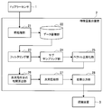
- FIG. 1 is an explanatory diagram showing an overview of a state recognition system according to an embodiment of the present invention.
- the state recognition system includes a Doppler sensor 1, a feature amount calculation device 2, and a recognition device 3.
- the Doppler sensor 1 is installed in, for example, a corner of a room, and transmits light, electromagnetic waves, or transmitted waves by sound waves toward the indoor area, which is a detection area, and is indoors such as a person or an animal.
- a reflected wave (received wave) reflected by a moving object (reflecting object) is received.
- FIG. 1 shows an example in which one person exists indoors, a plurality of persons or other animals than humans may be used.
- the Doppler sensor 1 generates a Doppler signal based on the transmission wave and the reception wave and outputs the Doppler signal to the feature amount calculation device 2. Then, the feature quantity calculation device 2 extracts a feature quantity for more accurately recognizing the state of the indoor moving body from the Doppler signal and outputs the feature quantity to the recognition device 3.
- the feature amount calculation apparatus 2 extracts a high-order local autocorrelation feature (HLAC: Higher-order Local AutoCorrelation) as such a feature amount.
- HLAC Higher-order Local AutoCorrelation
- a high-order local autocorrelation feature is a feature amount that represents a correlation amount of one signal or a plurality of signals in local time.
- a higher-order local autocorrelation feature by applying a higher-order local autocorrelation feature to a Doppler signal as a target, changes in periodicity and phase difference of motion (human body motion or biological signal) within the target area are detected. It becomes possible to extract.
- the recognition device 3 is in an “unmanned” state or a manned state indoors. Recognize whether there is. “Unmanned” means a state in which there is no person in the target area. “Rest” means that there is a person in the target area, but is not actively moving but is only breathing (for example, sitting on a chair or floor, standing, sleeping State, etc.). “Activity” means a state where a person is in the target area and is actively moving by moving a limb (moving, stepping, etc.). .
- FIG. 2 is a block diagram showing a configuration of a state recognition system according to an embodiment of the present invention.
- the state recognition system includes a Doppler sensor 1, a feature amount calculation device 2, and a recognition device 3.
- the Doppler sensor 1 has a function as an observation unit that observes a Doppler signal indicating the movement of a moving object in a space (detection area) to be observed.
- the Doppler sensor 1 has a configuration in which an output signal from a local oscillator is emitted from a transmission antenna and a reflected wave from an object is received by a reception antenna.
- the Doppler sensor 1 distributes the received signal into two by a distributor, and delays one signal by 90 degrees using a phase shifter. Since the reflected wave from the moving body is frequency-modulated by the Doppler effect, a phase difference is generated in each signal.
- V I (t) and V Q (t) two waves obtained by the Doppler sensor 1 and having a phase difference of 90 degrees are defined as V I (t) and V Q (t) as shown in the following formula 1. Note that the subscript I represents In-phase (in-phase), and Q represents Quadrature (quadrature phase).
- Equation 1 A is the amplitude of each signal, ⁇ is the wavelength, R (t) is the distance between the Doppler sensor 1 and the object at time t, ⁇ 0 is the initial phase, O is the DC offset, and w is the noise. It is an ingredient.
- Equation 1 see “Droitcour, AD et al.“ Range correlation and I / Q performance. benefits in single-chip silicon Doppler radars for noncontact cardiopulmonary monitoring ”Microwave Theory and Techniques, IEEE Transactions, Vol. 52, No. 3, pp. 838-848, March 2004. ”.
- the Doppler sensor 1 outputs the signals V I (t) and V Q (t) to the feature amount calculation device 2.
- the signals V I (t) and V Q (t) are also referred to as Doppler signals.
- the feature amount calculation device 2 extracts a feature amount indicating the state of the object in the detection area from the Doppler signal output by the Doppler sensor 1.
- the feature amount calculation apparatus 2 includes a preprocessing unit 21, a data storage unit 22, a filtering unit 23, a subsampling unit 24, a vector normalization unit 25, a higher-order local autocorrelation calculation unit 26, a dimension compression unit 27, and a result output unit. It functions as 28.
- the preprocessing unit 21 has a function as an acquisition unit that acquires a Doppler signal from the Doppler sensor 1 and a function of performing predetermined signal processing (preprocessing) on the Doppler signal.
- the preprocessing performed by the preprocessing unit 21 may include, for example, conversion to a digital signal by sampling signal intensity, signal offset adjustment, removal of a direct current component by applying a high-pass filter, and the like. Note that the feature amount calculation apparatus 2 can also cope with a case where different types of Doppler sensors 1 are connected by offset adjustment performed by the preprocessing unit 21.
- the Doppler sensor 1 and the preprocessing unit 21 are realized as separate hardware, but they may be realized as the same hardware.
- the preprocessing unit 21 may be included in the HMD 1, and the feature amount calculation device 2 may include the Doppler sensor 1. Further, the pre-processing unit 21 can sub-sample the acquired Doppler signal to remove a noise component superimposed by the power supply voltage and a redundant high-frequency region, thereby reducing the processing amount in the subsequent block. it can.
- the pre-processing unit 21 outputs the pre-processed Doppler signal to the data storage unit 22.
- the data storage unit 22 has a function of storing the Doppler signal output from the preprocessing unit 21.
- the data storage unit 22 is realized by, for example, a hard disk drive (HDD), a solid-state memory such as a flash memory, a memory card incorporating a fixed memory, an optical disk, a magneto-optical disk, or a hologram memory.
- the data storage unit 22 outputs the accumulated Doppler signal to the filtering unit 23.
- the present invention may be real-time or non-real-time.
- the data accumulation unit 22 may output the Doppler signal output from the preprocessing unit 21 to the filtering unit 23 in real time, or may output the accumulated Doppler signal in non-real time.
- the preprocessing unit 21 and the data storage unit 22 may be separated from the feature amount calculation device 2 and configured integrally with the Doppler sensor 1.
- the data storage unit 22 stores the signal observed by the Doppler sensor 1 and preprocessed by the preprocessing unit 21, and performs the subsequent processing separately by a personal computer having a general-purpose function.
- the sensing device can be reduced in size.
- the filtering unit 23 has a function as an extraction unit that extracts a time-series signal including a predetermined frequency component from the Doppler signal preprocessed by the preprocessing unit 21. Specifically, the filtering unit 23 performs frequency filtering on the Doppler signal output from the data storage unit 22.
- the sampling rate of the Doppler sensor is several kHz, but the human motion is about 0.1 to several tens of frequency components.
- the filtering unit 23 sets a cut-off frequency according to a frequency band that can be taken into account, for example, respiration, pulse, body motion, etc., and applies a bandpass filter or a lowpass filter to Only signal components resulting from the operation are extracted.
- the filtering in the filtering unit 23 is not limited to a specific method. As long as the digital signal can be filtered, the filtering unit 23 can select a method using a transform into the frequency domain by Fourier transform, an infinite impulse response (IIR) filter, a finite impulse response (FIR) filter, or the like. Can be selected.
- IIR infinite impulse response
- FIR finite impulse response
- the filtering unit 23 outputs the extracted signal to the subsampling unit 24.
- Sub-sampling unit 24 has a function as a selection unit that selects a signal value at a predetermined interval from the signal extracted by the filtering unit 23. More specifically, the sub-sampling unit 24 selects (sub-samples) a signal used by the higher-order local autocorrelation calculation unit 26 described later from the signal sequence output from the filtering unit 23.
- Equation 2 a higher-order local autocorrelation feature calculated by a later-described higher-order local autocorrelation calculation unit 26 is defined by Equation 2 below.
- ⁇ is the correlation width.
- the sub-sampling unit 24 selects a plurality of signals used when calculating the higher-order local autocorrelation feature expressed by Equation 2 above at intervals of the correlation width ⁇ .
- the sub-sampling unit 24 uses V I (t), V I (t + ⁇ ) used to calculate the second-order higher-order local autocorrelation features of the signals V I (t) and V Q (t). ), V I (t + 2 ⁇ ), V Q (t), V Q (t + ⁇ ), and V Q (t + 2 ⁇ ).
- the sub-sampling unit 24 may use a point ahead of V I (t) by the correlation width ⁇ , for example, if the signal V I (t + ⁇ ) as the selection method, or before and after ⁇ / 2 minutes A smoothed signal may be used by taking the average of.
- the sub-sampling unit 24 outputs the selected 6-point signals to the vector normalization unit 25.
- Vector normalization unit 25 The vector normalization unit 25 has a function of performing vector normalization on the signal selected by the sub-sampling unit 24. Specifically, the vector normalization unit 25 performs vector normalization defined by Equation 3 below to unify the size of the six-point vector to 1.
- the vector normalization unit 25 can relieve the difference in signal intensity based on the difference in the distance between the Doppler sensor 1 and the person to be detected by the vector normalization shown in Equation 3 above.
- the vector normalization unit 25 performs vector normalization on the six-point signals V I ′ (t), V I ′ (t + ⁇ ), V I ′ (t + 2 ⁇ ), V Q ′ (t), V Q ′ (t + ⁇ ), V Q ′ (t + 2 ⁇ ) is output to the higher-order local autocorrelation calculation unit 26.
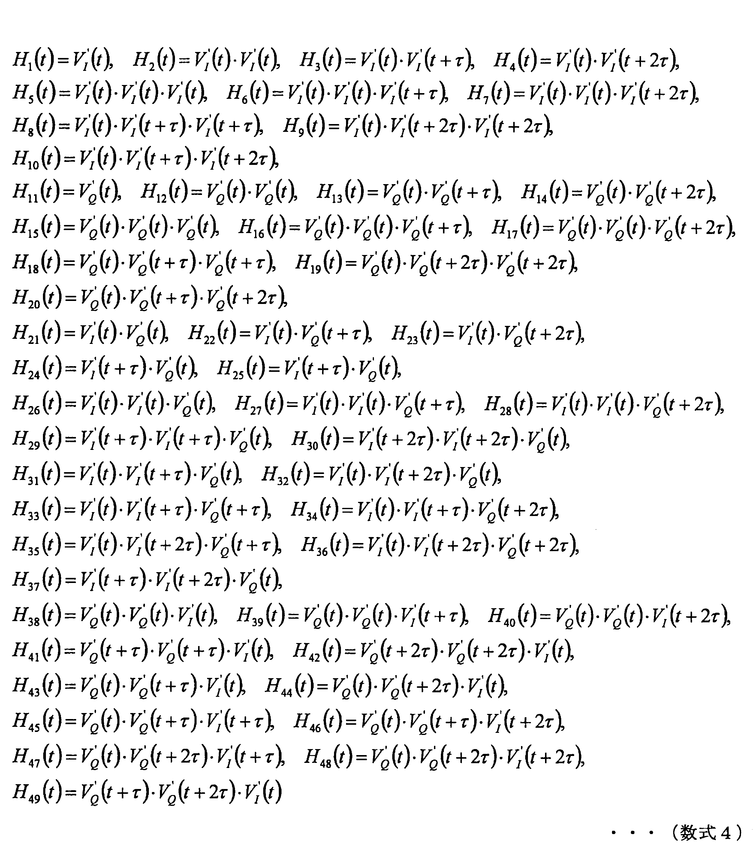
- the high-order local autocorrelation calculation unit 26 has a function as a calculation unit that calculates a high-order local autocorrelation feature based on the signal output from the vector normalization unit 25. More specifically, the high-order local autocorrelation calculation unit 26 is based on the 6-point signal output from the vector normalization unit 25, and has 49 patterns of high-order local autocorrelation features defined by the following Equation 4. Is calculated.
- the higher-order local autocorrelation calculation unit 26 outputs the calculated 49-pattern higher-order local autocorrelation features to the dimension compression unit 27.
- the dimension compression unit 27 has a function of performing dimension compression on the higher-order local autocorrelation features output from the higher-order local autocorrelation calculation unit 26.
- the dimension compression unit 27 performs dimension compression using a dimension compression technique such as principal component analysis. For this reason, the dimension compression part 27 can limit an efficient feature-value for the state recognition by the recognition apparatus 3 mentioned later.
- Dimension compression unit 27 outputs the result of dimension compression to result output unit 28.
- the result output unit 28 outputs the result output from the dimension compression unit 27 to the recognition device 3 as a feature amount indicating the state in the detection area. Note that the result output unit 28 may output the 49-pattern high-order local autocorrelation feature calculated by the high-order local autocorrelation calculation unit 26 as it is as a feature quantity indicating the state in the detection area.
- the recognition device 3 has a function as a recognition unit that recognizes the state of the detection area of the Doppler sensor 1 based on the feature amount (higher-order local autocorrelation feature) output from the result output unit 28.
- the recognition device 3 recognizes at least one of unattended, rest, and activity as the state of the space.
- the recognition apparatus 3 clusters and accumulates the feature values output from the result output unit 28 together with annotations such as “unmanned”, “rest”, and “activity”.
- the recognition device 3 calculates the similarity between the feature amount output from the result output unit 28 and the clustered state vector set, and recognizes the similar annotation as the state of the detection area.
- the recognition device 3 may use a support vector machine, a recognizer based on a hidden Markov model, or the like for calculating the similarity.
- the recognition device 3 may simply recognize one of the two states of “unmanned” and “manned” by collectively referring to “rest” and “activity” as “manned”.
- the recognition device 3 may be configured integrally with the feature amount calculation device 2.
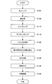
- FIG. 3 is a flowchart showing the operation of the state recognition system according to the embodiment of the present invention.
- the Doppler sensor 1 performs sensing of a detection area. Specifically, the Doppler sensor 1 emits an output signal from the local oscillator from the transmission antenna, receives a reflected wave from the object by the receiving antenna, and represents the above-described Expression 1 based on the reflected wave and the received wave. Two wave Doppler signals V I (t) and V Q (t) are obtained.
- step S ⁇ b> 108 the preprocessing unit 21 performs preprocessing on the two-wave Doppler signals V I (t) and V Q (t) output from the Doppler sensor 1.
- the preprocessing unit 21 performs conversion to a digital signal by sampling signal strength, signal offset adjustment, removal of a direct current component by applying a high-pass filter, and the like as preprocessing.
- the Doppler signal that has been preprocessed by the preprocessing unit 21 is accumulated by the data accumulation unit 22.
- the data storage unit 22 may output the Doppler signal output from the preprocessing unit 21 to the filtering unit 23 in real time, or may output the stored Doppler signal in non-real time.
- the filtering unit 23 performs filtering for extracting a frequency component resulting from human motion from the Doppler signal output from the data storage unit 22.
- the filtering unit 23 applies a band-pass filter or a low-pass filter so as to extract a frequency component of 0.1 to several tens Hz as a frequency band that can be taken into account, for example, respiration, pulse, body motion, and the like. .
- step S116 the sub-sampling unit 24 performs sub-sampling from the signal sequence filtered by the filtering unit 23. Specifically, the sub-sampling unit 24 performs V I (t), V I (t + ⁇ ), V I (t + 2 ⁇ ), V Q (t), V Q (t + ⁇ ), and V Q ( 6 points of t + 2 ⁇ ) are selected.
- step S120 the vector normalization unit 25 performs vector normalization on the signal output from the sub-sampling unit 24. Specifically, the vector normalization unit 25 performs the vector normalization represented by Equation 3 on the six-point signal, thereby obtaining a signal based on the difference in distance between the Doppler sensor 1 and the person to be detected. Reduce the difference in strength.
- step S124 the high-order local autocorrelation calculation unit 26 calculates a high-order local autocorrelation feature based on the signal output from the vector normalization unit 25. Specifically, the high-order local autocorrelation calculation unit 26 calculates the 49-order high-order local autocorrelation feature expressed by the above Equation 4 from the six signal values.
- the dimension compression unit 27 performs dimension compression on the higher-order local autocorrelation features output from the higher-order local autocorrelation calculation unit 26. Specifically, the dimension compression unit 27 uses the 49-pattern high-order local autocorrelation features output from the high-order local autocorrelation calculation unit 26 to perform efficient feature recognition for state recognition by principal component analysis or the like. Limit.
- step S132 the result output unit 28 outputs the feature amount output from the dimension compression unit 27.
- the result output unit 28 can output the result of the dimension compression processing in the dimension compression unit 27 in the form of data, characters, sounds, images, and the like.
- step S136 the recognition device 3 recognizes the state of the detection area of the Doppler sensor 1 based on the feature amount output from the result output unit 28. Specifically, the recognition device 3 applies a support vector machine, a recognizer based on a hidden Markov model, or the like to confirm that the state of the space is “unattended”, “rest”, or “activity”. recognize.
- the feature amount calculation apparatus 2 uses a higher-order local autocorrelation feature to obtain a signal indicating periodicity and change in phase difference of movement (human body movement or biological signal) in a target area. It is possible to extract a feature quantity different from the amplitude and frequency of the. For this reason, the recognition device 3 has a case where a signal intensity similar to a Doppler signal obtained from human biological information is observed, such as when there is a small animal, or a home appliance that operates in a cycle similar to the human respiratory cycle. But we can distinguish humans from other disturbances. Therefore, the recognition device 3 can more accurately detect the state in the detection area based on the feature amount calculated by the feature amount calculation device 2.
- a Doppler signal in a predetermined section is converted into a frequency domain by FFT, and an average frequency in the same frequency band as that of the feature amount calculation device 2 is calculated as a feature amount.
- FFT short-time Fourier transform
- FIG. 4 is a diagram showing a frequency distribution of an average frequency by 1-second section FFT.
- FIG. 5 is a diagram showing the frequency distribution of the average frequency by 10-second section FFT.
- FIG. 4 it is difficult to determine the difference in feature amount depending on the presence or absence of a person in the 1-second FFT.
- FIG. 5 it can be seen that in the FFT in the 10 second section, the manned feature amount distribution is distributed with a value larger than the unattended feature amount distribution. That is, it is considered that the feature quantity by FFT in the 10-second section is useful for the discrimination of manned / unmanned.
- the feature quantity by FFT is useful for discrimination of manned / unmanned only when there is data of a long section of about 10 seconds.
- the high-order local autocorrelation feature is useful for discrimination of manned / unmanned even for data of a short interval of about 1 second.
- the correlation width ⁇ is 0.5 seconds (250 samples when the sampling frequency is 500 Hz), and the first of the higher-order local autocorrelation features calculated by the feature amount calculation device 2 with respect to the Doppler signal of 1 second interval.
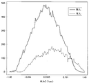
- the distribution of manned and unmanned one main component is shown in FIG.
- FIG. 6 is a diagram showing the frequency distribution of the first principal component of the high-order local autocorrelation feature in the 1-second interval according to an embodiment of the present invention. As shown in FIG. 6, it can be seen that the manned feature amount distribution is distributed with a value larger than the unattended feature amount distribution even in the 1 second section. As described above, the feature amount calculation apparatus 2 according to the embodiment of the present invention is useful for discrimination of manned / unmanned even if it is data of a short section in which it is difficult to calculate a useful feature amount in the comparative example. The amount can be calculated.
- the sampling frequency is 500 Hz
- the number of samples to be subjected to FFT calculation in a 1-second section is 500.
- V I (t), V I (t + ⁇ ), V I (t + 2 ⁇ ), V Q (t) , V Q (t + ⁇ ), and V Q (t + 2 ⁇ ) are the calculation targets. That is, the feature amount calculation apparatus 2 according to an embodiment of the present invention can significantly reduce the number of samples to be calculated as compared with the comparative example, and as a result, a calculation for calculating the feature amount. The amount can be reduced.
- the feature value calculation apparatus 2 can extract a feature value for more accurately recognizing the state of a moving object such as a human from a Doppler signal.
- the feature quantity calculation device 2 can calculate a useful feature quantity using data in a shorter section than the conventional method.
- the feature amount calculation apparatus 2 can reduce the amount of calculation for calculating the feature amount as compared with the conventional method.
- the state of the detection area is recognized for a human, but the present invention is not limited to such an example.
- the feature quantity calculation device 2 targets any moving object other than a human by setting the component filtered by the filtering unit 23 to a frequency band resulting from biological information such as breathing and heart motion of an animal other than a human. be able to.
- Doppler sensor 1 feature quantity calculation device 2
- Pre-processing unit 21 Pre-processing unit 21
- Data storage unit 22 Filtering unit 23
- Subsampling unit 24 25
- Vector normalization unit 25 Higher-order local autocorrelation calculation unit 26
- 27-dimensional compression unit 27 28
- Result Output Unit 28 Recognition device 3
Landscapes
- Engineering & Computer Science (AREA)
- Physics & Mathematics (AREA)
- Remote Sensing (AREA)
- Radar, Positioning & Navigation (AREA)
- Health & Medical Sciences (AREA)
- General Physics & Mathematics (AREA)
- Computer Networks & Wireless Communication (AREA)
- Life Sciences & Earth Sciences (AREA)
- Public Health (AREA)
- Medical Informatics (AREA)
- Biomedical Technology (AREA)
- General Health & Medical Sciences (AREA)
- Pathology (AREA)
- Acoustics & Sound (AREA)
- Electromagnetism (AREA)
- Radiology & Medical Imaging (AREA)
- Molecular Biology (AREA)
- Surgery (AREA)
- Animal Behavior & Ethology (AREA)
- Nuclear Medicine, Radiotherapy & Molecular Imaging (AREA)
- Biophysics (AREA)
- Veterinary Medicine (AREA)
- Heart & Thoracic Surgery (AREA)
- Physiology (AREA)
- Computer Vision & Pattern Recognition (AREA)
- Data Mining & Analysis (AREA)
- Databases & Information Systems (AREA)
- Epidemiology (AREA)
- Primary Health Care (AREA)
- Radar Systems Or Details Thereof (AREA)
- Measurement Of The Respiration, Hearing Ability, Form, And Blood Characteristics Of Living Organisms (AREA)
- Optical Radar Systems And Details Thereof (AREA)
- Measurement Of Velocity Or Position Using Acoustic Or Ultrasonic Waves (AREA)
Abstract
【課題】人間などの動体の状態をより正確に認識するための特徴量をドップラー信号から抽出することが可能な特徴量算出装置、特徴量算出方法および記録媒体を提供する。 【解決手段】 ドップラー信号を取得する取得部と、前記取得部により取得された前記ドップラー信号から所定の周波数成分から成る時系列信号を抽出する抽出部と、前記抽出部により抽出された前記時系列信号から所定間隔で信号値を選択する選択部と、前記選択部により選択された前記信号値に基づいて高次局所自己相関特徴を算出する算出部と、を備える特徴量算出装置。
Description
本発明は、特徴量算出装置、特徴量算出方法および記録媒体に関する。
近年、屋内などの特定エリアにセンサを設置して、その場所にいる人間の状態などを検知する技術が開発されている。
例えば、下記特許文献1および2で開示された技術は、センサから得られる体動や生体情報に基づき、人間の屋内での在室等を検知している。より詳しくは、特許文献1では、屋内に照射したドップラーセンサの信号の強度と分散値とから閾値判定を行い、屋内の状態を不在、休息、活動の3つの状態で推定する技術が開示されている。また、特許文献2では、生活機器に装着された圧力センサの信号を、周波数変換及びフィルタリング処理することで、呼吸成分、心拍成分、体動成分を抽出し、これらの成分から不在か否か、また緊急時の検出を行う技術が開示されている。
また、下記特許文献3で開示された技術は、睡眠時の見守りを目的とした、睡眠状態の分別や異常の検知を行っている。より詳しくは、特許文献3には、ベッドで寝ている人間に向けてドップラーセンサから信号を照射し、ドップラー信号から得られる動作時間、速度、方向などの情報から閾値判定を行なって、呼吸、寝返り、ベッドからの落下等を検知する技術が開示されている。
しかし、上記特許文献1~3で開示された技術では、人間の生体情報のうち、信号強度や分散、周波数成分、センサに対する速度など一部の情報のみを利用しているため、エリア内にそれらの情報と似た外乱がある場合、誤検知が生じ得るという問題があった。
例えば、上記特許文献1で開示された技術では、ペットや害虫など小動物がいる場合、信号強度とその分散だけでは人間との識別が困難である。また、上記特許文献2で開示された技術では、人の呼吸周期と似た周波数成分で動作する家電機器があった場合、正確な生体情報を検出することができない。さらに、特許文献3に開示された技術では、ベッド上での人間の見守りに特化しているため、ベッド上という限られた空間では人間の呼吸や体動を抽出できるが、屋内全体など広範囲への適用を考えた場合に、外乱との区別が考慮されていないという問題がある。
そこで、本発明は、上記問題に鑑みてなされたものであり、本発明の目的とするところは、人間などの動体の状態をより正確に認識するための特徴量をドップラー信号から抽出することが可能な、新規かつ改良された特徴量算出装置、特徴量算出方法および記録媒体を提供することにある。
上記課題を解決するために、本発明のある観点によれば、ドップラー信号を取得する取得部と、前記取得部により取得された前記ドップラー信号から所定の周波数成分から成る時系列信号を抽出する抽出部と、前記抽出部により抽出された前記時系列信号から所定間隔で信号値を選択する選択部と、前記選択部により選択された前記信号値に基づいて高次局所自己相関特徴を算出する算出部と、を備える特徴量算出装置が提供される。
前記特徴量算出装置は、前記選択部により選択された前記信号値に対してベクトル正規化を行うベクトル正規化部をさらに備え、前記算出部は、前記ベクトル正規化部により正規化された前記信号値に基づいて前記高次局所自己相関特徴を算出してもよい。
前記特徴量算出装置は、前記算出部により算出された前記高次局所自己相関特徴に対して次元圧縮を行う次元圧縮部をさらに備えてもよい。
前記特徴量算出装置は、前記取得部により取得された前記ドップラー信号に対して所定の信号処理を行う前処理部をさらに備え、前記抽出部は、前記前処理部により信号処理された前記ドップラー信号から前記時系列信号を抽出してもよい。
前記前処理部は、前記取得部により取得された前記ドップラー信号に対してオフセット調整を行ってもよい。
前記抽出部は、前記取得部により取得された前記ドップラー信号から、人間の動作に起因する周波数成分から成る前記時系列信号を抽出してもよい。
前記特徴量算出装置は、前記算出部により算出された前記高次局所自己相関特徴に基づいて、前記取得部により取得された前記ドップラー信号の観測対象の空間の状態を認識する認識部をさらに備えてもよい。
前記認識部は、前記空間の状態として、無人、安静、活動のうちの少なくともいずれか1つを認識してもよい。
前記特徴量算出装置は、前記ドップラー信号を観測して前記取得部に出力する観測部をさらに備えてもよい。
また、上記課題を解決するために、本発明の別の観点によれば、ドップラー信号を取得するステップと、取得された前記ドップラー信号から所定の周波数成分から成る時系列信号を抽出するステップと、抽出された前記時系列信号から所定間隔で信号値を選択するステップと、選択された前記信号値に基づいて高次局所自己相関特徴を算出するステップと、を備える特徴量算出方法が提供される。
また、上記課題を解決するために、本発明の別の観点によれば、コンピュータに、ドップラー信号を取得するステップと、取得された前記ドップラー信号から所定の周波数成分から成る時系列信号を抽出するステップと、抽出された前記時系列信号から所定間隔で信号値を選択するステップと、選択された前記信号値に基づいて高次局所自己相関特徴を算出するステップと、を実行させるためのプログラムを記録した記録媒体が提供される。
以上説明したように本発明によれば、人間などの動体の状態をより正確に認識するための特徴量をドップラー信号から抽出することが可能である。
以下に添付図面を参照しながら、本発明の好適な実施の形態について詳細に説明する。なお、本明細書及び図面において、実質的に同一の機能構成を有する構成要素については、同一の符号を付することにより重複説明を省略する。
<1.本発明の一実施形態に係る状態認識システムの概要>
まず、本発明の一実施形態に係る状態認識システムの概要について、図1を参照して説明する。
まず、本発明の一実施形態に係る状態認識システムの概要について、図1を参照して説明する。
図1は、本発明の一実施形態に係る状態認識システムの概要を示す説明図である。図1に示すように、本発明の一実施形態に係る状態認識システムは、ドップラーセンサ1、特徴量算出装置2、および認識装置3を有する。図1に示すように、ドップラーセンサ1は例えば部屋の一角に設置され、検知エリアである屋内に向けて、光、電磁波、または音波による送信波を送信して、人や動物など、屋内にいる動体(反射物体)により反射された反射波(受信波)を受信している。なお、図1では屋内に人間が一人存在する例を示しているが、複数人であってもよいし、人間以外の他の動物であってもよい。
ドップラーセンサ1は、送信波と受信波に基づいてドップラー信号を生成して、特徴量算出装置2に出力する。そして、特徴量算出装置2は、ドップラー信号から屋内の動体の状態をより正確に認識するための特徴量を抽出して、認識装置3に出力する。
本発明の一実施形態に係る特徴量算出装置2は、このような特徴量として、高次局所自己相関特徴(HLAC:Higher-order Local AutoCorrelation)を抽出する。高次局所自己相関特徴とは、局所時間における一信号または複数信号の相関量を表す特徴量である。本発明の一実施形態では、ドップラー信号を対象として高次局所自己相関特徴を適用することにより、対象とするエリア内の動き(人間の体動や生体信号)の周期性および位相差の変化を抽出することが可能となる。
認識装置3は、特徴量算出装置2により抽出された特徴量に基づいて、屋内が「無人」状態であるか有人であるか、有人の場合は「活動」状態であるか「安静」状態であるか、を認識する。なお、「無人」とは、対象とするエリア内に人間がいない状態を意味するものとする。「安静」とは、対象とするエリア内に人間はいるが、能動的に動かずに呼吸のみをしている状態(例えば、椅子や床に座っている状態、立っている状態、寝ている状態等)を意味するものとする。「活動」とは、対象とするエリア内に人間がいて、手足を動かすなどして能動的に動作をしている状態(移動している、足踏みをしている等)を意味するものとする。
以上、状態認識システムの概要について説明した。以下では、図2~図6を参照して、本発明の一実施形態に係る状態認識システムについて詳細に説明する。
<2.本発明の一実施形態>
[2-1.構成]
図2は、本発明の一実施形態に係る状態認識システムの構成を示すブロック図である。図2に示すように、状態認識システムは、ドップラーセンサ1、特徴量算出装置2、および認識装置3を有する。
[2-1.構成]
図2は、本発明の一実施形態に係る状態認識システムの構成を示すブロック図である。図2に示すように、状態認識システムは、ドップラーセンサ1、特徴量算出装置2、および認識装置3を有する。
(ドップラーセンサ1)
ドップラーセンサ1は、観測対象とする空間(検知エリア)内の動体の動きを示すドップラー信号を観測する観測部としての機能を有する。ドップラーセンサ1は、局部発振器からの出力信号を送信アンテナから出射し、対象物からの反射波を受信アンテナで受信する構成を備える。ドップラーセンサ1は、対象物からの反射波を受信アンテナで受信すると、受信信号を分配器で2つに分配させ、位相器を用いて片方の信号を90度遅らせる。動体からの反射波は、ドップラー効果により周波数変調されるので、各々の信号に位相差が発生する。
ドップラーセンサ1は、観測対象とする空間(検知エリア)内の動体の動きを示すドップラー信号を観測する観測部としての機能を有する。ドップラーセンサ1は、局部発振器からの出力信号を送信アンテナから出射し、対象物からの反射波を受信アンテナで受信する構成を備える。ドップラーセンサ1は、対象物からの反射波を受信アンテナで受信すると、受信信号を分配器で2つに分配させ、位相器を用いて片方の信号を90度遅らせる。動体からの反射波は、ドップラー効果により周波数変調されるので、各々の信号に位相差が発生する。
本実施形態では、ドップラーセンサ1によって得られる、位相が90度異なる2波を、下記の数式1に示すようにVI(t),VQ(t)とする。なお、添字のIはIn-phase(同相)、QはQuadratute(直角位相)を表す。

ここで、数式1において、Aは各信号の振幅、λは波長、R(t)は時刻tにおけるドップラーセンサ1と対象物との距離、φ0は初期位相、Oは直流オフセット、wはノイズ成分である。なお、数式1の導出については、「Droitcour, A.D. et al. “Range correlation and I/Q performance
benefits in single-chip silicon Doppler radars for noncontact cardiopulmonary
monitoring” Microwave Theory and Techniques, IEEE Transactions, Vol. 52, No. 3,
pp. 838-848, March 2004.」に開示されている。
benefits in single-chip silicon Doppler radars for noncontact cardiopulmonary
monitoring” Microwave Theory and Techniques, IEEE Transactions, Vol. 52, No. 3,
pp. 838-848, March 2004.」に開示されている。
ドップラーセンサ1は、信号VI(t)およびVQ(t)を、特徴量算出装置2に出力する。以下では、信号VI(t)およびVQ(t)を、ドップラー信号とも称する。
(特徴量算出装置2)
特徴量算出装置2は、ドップラーセンサ1により出力されたドップラー信号から、検知エリア内の対象物の状態を示す特徴量を抽出する。特徴量算出装置2は、前処理部21、データ蓄積部22、フィルタリング部23、サブサンプリング部24、ベクトル正規化部25、高次局所自己相関算出部26、次元圧縮部27、および結果出力部28として機能する。
特徴量算出装置2は、ドップラーセンサ1により出力されたドップラー信号から、検知エリア内の対象物の状態を示す特徴量を抽出する。特徴量算出装置2は、前処理部21、データ蓄積部22、フィルタリング部23、サブサンプリング部24、ベクトル正規化部25、高次局所自己相関算出部26、次元圧縮部27、および結果出力部28として機能する。
・前処理部21
前処理部21は、ドップラーセンサ1からドップラー信号を取得する取得部としての機能と、ドップラー信号に対して所定の信号処理(前処理)を行う機能とを有する。前処理部21が行う前処理には、例えば信号強度のサンプリングによるデジタル信号への変換、信号のオフセット調整、ハイパスフィルタを適用することによる直流成分の除去等が含まれ得る。なお、特徴量算出装置2は、前処理部21が行うオフセット調整により、異なる種類のドップラーセンサ1が接続された場合にも対応することができる。
前処理部21は、ドップラーセンサ1からドップラー信号を取得する取得部としての機能と、ドップラー信号に対して所定の信号処理(前処理)を行う機能とを有する。前処理部21が行う前処理には、例えば信号強度のサンプリングによるデジタル信号への変換、信号のオフセット調整、ハイパスフィルタを適用することによる直流成分の除去等が含まれ得る。なお、特徴量算出装置2は、前処理部21が行うオフセット調整により、異なる種類のドップラーセンサ1が接続された場合にも対応することができる。
図2に示した構成では、ドップラーセンサ1と前処理部21とが別々のハードウェアとして実現される例を示したが、同一のハードウェアとして実現されてもよい。具体的には、HMD1に前処理部21が含まれていてもよいし、特徴量算出装置2がドップラーセンサ1を含んでもよい。また、前処理部21は、取得したドップラー信号をサブサンプリングすることで、電源電圧によって重畳されるノイズ成分や、冗長な高周波領域を除去して、後段のブロックでの処理量を低減させることができる。
前処理部21は、前処理を行ったドップラー信号を、データ蓄積部22に出力する。
・データ蓄積部22
データ蓄積部22は、前処理部21から出力されたドップラー信号を蓄積する機能を有する。データ蓄積部22は、例えばHDD(Hard Disc Drive)、フラッシュメモリ等の固体メモリ、固定メモリを内蔵したメモリカード、光ディスク、光磁気ディスク、ホログラムメモリにより実現される。
データ蓄積部22は、前処理部21から出力されたドップラー信号を蓄積する機能を有する。データ蓄積部22は、例えばHDD(Hard Disc Drive)、フラッシュメモリ等の固体メモリ、固定メモリを内蔵したメモリカード、光ディスク、光磁気ディスク、ホログラムメモリにより実現される。
データ蓄積部22は、蓄積したドップラー信号をフィルタリング部23に出力する。
なお、本発明は、リアルタイム、非リアルタイムを問わない。このため、データ蓄積部22は、前処理部21から出力されたドップラー信号をリアルタイムにフィルタリング部23に出力してもよいし、蓄積したドップラー信号を非リアルタイムに出力してもよい。また、前処理部21およびデータ蓄積部22は、特徴量算出装置2から分離してドップラーセンサ1と一体的に構成されてもよい。この場合、データ蓄積部22は、ドップラーセンサ1により観測され、前処理部21により前処理された信号を保存しておき、その後の処理を別途、汎用の機能をもつパーソナルコンピュータ等により行うことで、センシングを行う装置を小型化することができる。
・フィルタリング部23
フィルタリング部23は、前処理部21により前処理されたドップラー信号から、所定の周波数成分から成る時系列信号を抽出する抽出部としての機能を有する。具体的には、フィルタリング部23は、データ蓄積部22から出力されたドップラー信号に対して周波数フィルタリングを行う。
フィルタリング部23は、前処理部21により前処理されたドップラー信号から、所定の周波数成分から成る時系列信号を抽出する抽出部としての機能を有する。具体的には、フィルタリング部23は、データ蓄積部22から出力されたドップラー信号に対して周波数フィルタリングを行う。
ここで、一般的に、ドップラーセンサのサンプリングレートは数kHzであるが、人間の動作は0.1~数十Hzの周波数成分程度である。このため、フィルタリング部23は、着目すべき成分、例えば呼吸、脈拍、体動などが取りうる周波数帯に応じてカットオフ周波数を設定し、バンドパスフィルタもしくはローパスフィルタを適用することで、人間の動作に起因する信号成分のみを抽出する。
なお、フィルタリング部23でのフィルタリングは特定の方法に限定されるものではない。デジタル信号をフィルタリングすることができるものであれば、フィルタリング部23は、フーリエ変換による周波数領域への変換を用いた方法、無限インパルス応答(IIR)フィルタ、有限インパルス応答(FIR)フィルタ等の中から選択され得る。
フィルタリング部23は、抽出した信号をサブサンプリング部24に出力する。
・サブサンプリング部24
サブサンプリング部24は、フィルタリング部23により抽出された信号から所定間隔で信号値を選択する選択部としての機能を有する。より具体的には、サブサンプリング部24は、フィルタリング部23から出力された信号系列から、後述の高次局所自己相関算出部26により使用される信号を選定(サブサンプリング)する。
サブサンプリング部24は、フィルタリング部23により抽出された信号から所定間隔で信号値を選択する選択部としての機能を有する。より具体的には、サブサンプリング部24は、フィルタリング部23から出力された信号系列から、後述の高次局所自己相関算出部26により使用される信号を選定(サブサンプリング)する。
ここで、後述の高次局所自己相関算出部26が算出する高次局所自己相関特徴を、下記の数式2で定義する。

なお、上記数式2において、τは相関幅である。サブサンプリング部24は、上記数式2で示した高次局所自己相関特徴を算出する際に使用される複数の信号を、相関幅τの間隔で選定する。本実施形態では、サブサンプリング部24は、信号VI(t)およびVQ(t)の2次の高次局所自己相関特徴の算出に使用される、VI(t)、VI(t+τ)、VI(t+2τ)、VQ(t)、VQ(t+τ)、VQ(t+2τ)の6点を選定する。なお、サブサンプリング部24は、選定の方法として例えば、信号VI(t+τ)であればVI(t)から相関幅τ分だけ先の点を使用してもよいし、前後τ/2分の平均を取って平滑化した信号を用いてもよい。
サブサンプリング部24は、選択した6点の信号をベクトル正規化部25に出力する。
・ベクトル正規化部25
ベクトル正規化部25は、サブサンプリング部24により選択された信号に対してベクトル正規化を行う機能を有する。具体的には、ベクトル正規化部25は、下記の数式3で定義するベクトル正規化を行って、6点のベクトルの大きさを1に統一する。
ベクトル正規化部25は、サブサンプリング部24により選択された信号に対してベクトル正規化を行う機能を有する。具体的には、ベクトル正規化部25は、下記の数式3で定義するベクトル正規化を行って、6点のベクトルの大きさを1に統一する。

ベクトル正規化部25は、上記の数式3で示したベクトル正規化により、ドップラーセンサ1と検知対象の人間との距離の違いに基づく信号強度の差を緩和することができる。
ベクトル正規化部25は、ベクトル正規化した6点の信号VI´(t)、VI´(t+τ)、VI´(t+2τ)、VQ´(t)、VQ´(t+τ)、VQ´(t+2τ)を、高次局所自己相関算出部26に出力する。
・高次局所自己相関算出部26
高次局所自己相関算出部26は、ベクトル正規化部25から出力された信号に基づいて高次局所自己相関特徴を算出する算出部としての機能を有する。より具体的には、高次局所自己相関算出部26は、ベクトル正規化部25から出力された6点の信号に基づいて、下記の数式4で定義する全49パタンの高次局所自己相関特徴を算出する。
高次局所自己相関算出部26は、ベクトル正規化部25から出力された信号に基づいて高次局所自己相関特徴を算出する算出部としての機能を有する。より具体的には、高次局所自己相関算出部26は、ベクトル正規化部25から出力された6点の信号に基づいて、下記の数式4で定義する全49パタンの高次局所自己相関特徴を算出する。
高次局所自己相関算出部26は、算出した49パタンの高次局所自己相関特徴を次元圧縮部27に出力する。
・次元圧縮部27
次元圧縮部27は、高次局所自己相関算出部26から出力された高次局所自己相関特徴に対して次元圧縮を行う機能を有する。例えば、次元圧縮部27は、主成分分析などの次元圧縮手法を用いて次元圧縮を行う。このため、次元圧縮部27は、後述する認識装置3による状態認識のために効率のよい特徴量を限定することができる。
次元圧縮部27は、高次局所自己相関算出部26から出力された高次局所自己相関特徴に対して次元圧縮を行う機能を有する。例えば、次元圧縮部27は、主成分分析などの次元圧縮手法を用いて次元圧縮を行う。このため、次元圧縮部27は、後述する認識装置3による状態認識のために効率のよい特徴量を限定することができる。
次元圧縮部27は、次元圧縮した結果を、結果出力部28に出力する。
・結果出力部28
結果出力部28は、次元圧縮部27から出力された結果を、検知エリア内の状態を示す特徴量として認識装置3に出力する。なお、結果出力部28は、高次局所自己相関算出部26により算出された49パタンの高次局所自己相関特徴を、検知エリア内の状態を示す特徴量としてそのまま出力してもよい。
結果出力部28は、次元圧縮部27から出力された結果を、検知エリア内の状態を示す特徴量として認識装置3に出力する。なお、結果出力部28は、高次局所自己相関算出部26により算出された49パタンの高次局所自己相関特徴を、検知エリア内の状態を示す特徴量としてそのまま出力してもよい。
(認識装置3)
認識装置3は、結果出力部28から出力された特徴量(高次局所自己相関特徴)に基づいて、ドップラーセンサ1の検知エリアの状態を認識する認識部としての機能を有する。認識装置3は、空間の状態として、無人、安静、活動のうちの少なくともいずれか1つを認識する。
認識装置3は、結果出力部28から出力された特徴量(高次局所自己相関特徴)に基づいて、ドップラーセンサ1の検知エリアの状態を認識する認識部としての機能を有する。認識装置3は、空間の状態として、無人、安静、活動のうちの少なくともいずれか1つを認識する。
具体的には、まず、認識装置3は、結果出力部28から出力された特徴量を、「無人」、「安静」、「活動」などのアノテーションとともにクラスタリングして蓄積しておく。そして、認識装置3は、結果出力部28から出力された特徴量と、クラスタリングされた状態ベクトルの集合との類似度を算出して、類似するアノテーションを検知エリアの状態として認識する。認識装置3は、類似度の算出にサポートベクタマシンや隠れマルコフモデルに基づく認識器等を使用してもよい。
なお、認識装置3は、「安静」および「活動」を「有人」と総称することで、単に「無人」と「有人」の2つの状態のいずれかを認識してもよい。また、認識装置3は、特徴量算出装置2と一体的に構成されていてもよい。
以上、本実施形態に係る状態システムの構成について説明した。続いて、図3を参照して、本実施形態に係る状態システムの動作処理について説明する。
[2-2.動作処理]
図3は、本発明の一実施形態に係る状態認識システムの動作を示すフローチャートである。図3に示すように、まず、ステップS104で、ドップラーセンサ1は、検知エリアのセンシングを行う。具体的には、ドップラーセンサ1は、局部発振器からの出力信号を送信アンテナから出射し、対象物からの反射波を受信アンテナで受信して、反射波と受信波に基づいて上記数式1で示した2波のドップラー信号VI(t)、VQ(t)を得る。
図3は、本発明の一実施形態に係る状態認識システムの動作を示すフローチャートである。図3に示すように、まず、ステップS104で、ドップラーセンサ1は、検知エリアのセンシングを行う。具体的には、ドップラーセンサ1は、局部発振器からの出力信号を送信アンテナから出射し、対象物からの反射波を受信アンテナで受信して、反射波と受信波に基づいて上記数式1で示した2波のドップラー信号VI(t)、VQ(t)を得る。
次いで、ステップS108で、前処理部21は、ドップラーセンサ1から出力された2波のドップラー信号VI(t),VQ(t)に対して、前処理を行う。例えば、前処理部21は、前処理として、信号強度のサンプリングによるデジタル信号への変換、信号のオフセット調整、ハイパスフィルタを適用することによる直流成分の除去等を行う。
前処理部21により前処理が行われたドップラー信号は、データ蓄積部22により蓄積される。ここで、データ蓄積部22は、前処理部21から出力されたドップラー信号をリアルタイムにフィルタリング部23に出力してもよいし、蓄積したドップラー信号を非リアルタイムに出力してもよい。
次に、ステップS112で、フィルタリング部23は、データ蓄積部22から出力されたドップラー信号から、人間の動作に起因する周波数成分を抽出するためのフィルタリングを行う。例えば、フィルタリング部23は、着目すべき成分、例えば呼吸、脈拍、体動などが取りうる周波数帯として、0.1~数十Hzの周波数成分を抽出するようバンドパスフィルタもしくはローパスフィルタを適用する。
次いで、ステップS116で、サブサンプリング部24は、フィルタリング部23によりフィルタリングされた信号系列からサブサンプリングを行う。具体的には、サブサンプリング部24は、上記数式3で示したVI(t)、VI(t+τ)、VI(t+2τ)、VQ(t)、VQ(t+τ)、VQ(t+2τ)の6点を選定する。
次に、ステップS120で、ベクトル正規化部25は、サブサンプリング部24から出力された信号に対してベクトル正規化を行う。具体的には、ベクトル正規化部25は、6点の信号に対して、上記数式3で示したベクトル正規化を行うことで、ドップラーセンサ1と検知対象の人間との距離の違いに基づく信号強度の差を緩和する。
そして、ステップS124で、高次局所自己相関算出部26は、ベクトル正規化部25から出力された信号に基づいて、高次局所自己相関特徴を算出する。具体的には、高次局所自己相関算出部26は、6点の信号値から、上記数式4で示した49パタンの高次局所自己相関特徴を算出する。
次いで、ステップS128で、次元圧縮部27は、高次局所自己相関算出部26から出力された高次局所自己相関特徴に対して次元圧縮を行う。具体的には、次元圧縮部27は、高次局所自己相関算出部26から出力された49パタンの高次局所自己相関特徴から、主成分分析などにより、状態認識のために効率のよい特徴量を限定する。
次に、ステップS132で、結果出力部28は、次元圧縮部27から出力された特徴量を出力する。このとき、結果出力部28は、次元圧縮部27での次元圧縮処理の結果を、データ、文字、音声、画像等の形態で出力し得る。
そして、ステップS136で、認識装置3は、結果出力部28から出力された特徴量に基づいて、ドップラーセンサ1の検知エリアの状態を認識する。具体的には、認識装置3は、サポートベクタマシンや隠れマルコフモデルに基づく認識器等を適用することにより、空間の状態が「無人」、「安静」、「活動」のいずれかであることを認識する。
以上、本実施形態に係る状態システムの動作処理について説明した。続いて、図4~図6を参照して、本実施形態に係る状態システムが奏する効果について説明する。
[2-3.効果]
本実施形態にかかる特徴量算出装置2は、高次局所自己相関特徴を用いることで、対象とするエリア内の動き(人間の体動や生体信号)の周期性および位相差の変化という、信号の振幅や周波数と異なる特徴量を抽出することができる。このため、認識装置3は、小動物がいる場合など人間の生体情報から得られるドップラー信号と同様の信号強度が観測される場合や、人の呼吸周期と似た周期で動作する家電機器がある場合でも、人間とその他の外乱とを識別することができる。よって、認識装置3は、特徴量算出装置2により算出された特徴量により、検知エリア内の状態をより正確に検出することができる。
本実施形態にかかる特徴量算出装置2は、高次局所自己相関特徴を用いることで、対象とするエリア内の動き(人間の体動や生体信号)の周期性および位相差の変化という、信号の振幅や周波数と異なる特徴量を抽出することができる。このため、認識装置3は、小動物がいる場合など人間の生体情報から得られるドップラー信号と同様の信号強度が観測される場合や、人の呼吸周期と似た周期で動作する家電機器がある場合でも、人間とその他の外乱とを識別することができる。よって、認識装置3は、特徴量算出装置2により算出された特徴量により、検知エリア内の状態をより正確に検出することができる。
以下では、従来手法のひとつである、短時間フーリエ変換(FFT:Fast Fourier Transform)により特徴量を抽出する手法を比較例として、本実施形態に係る状態システムが奏する効果を説明する。比較例は、所定区間のドップラー信号をFFTにより周波数領域に変換して、特徴量算出装置2と同一周波数帯の平均周波数を特徴量として算出する。以下、比較例により算出された平均周波数の有人と無人の分布を、図4および図5に示す。
図4は、1秒区間FFTによる平均周波数の度数分布を示す図である。図5は、10秒区間FFTによる平均周波数の度数分布を示す図である。図4に示すように、1秒区間のFFTでは、人の有無による特徴量の違いを判断することが難しい。一方で、図5に示すように、10秒区間のFFTでは、有人の特徴量分布の方が無人の特徴量分布より大きい値で分布していることが分かる。つまり、10秒区間のFFTによる特徴量は、有人/無人の判別に有用であると考えられる。しかしながら、図4および図5に示した例からは、FFTによる特徴量は、10秒程度の長い区間のデータがあって初めて、有人/無人の判別に有用となる、とも言える。
これに対し、本発明の一実施形態による高次局所自己相関特徴は、1秒程度の短い区間のデータであっても、有人/無人の判別に有用である。以下、相関幅τを0.5秒(サンプリング周波数が500Hzの場合は250サンプル)として、1秒区間のドップラー信号に対して特徴量算出装置2により算出された、高次局所自己相関特徴の第1主成分の有人と無人の分布を図6に示す。
図6は、本発明の一実施形態による1秒区間の高次局所自己相関特徴の第1主成分の度数分布を示す図である。図6に示すように、1秒区間であっても、有人の特徴量分布の方が無人の特徴量分布より大きい値で分布していることが分かる。このように、本発明の一実施形態による特徴量算出装置2は、比較例では有用な特徴量を算出することが困難な短い区間のデータであっても、有人/無人の判別に有用な特徴量を算出することができる。
また、例えばサンプリング周波数を500Hzとした場合、比較例において、1秒区間のFFTの計算対象となるサンプル数は500である。これに対し、本発明の一実施形態に係る特徴量算出装置2では、1秒区間であっても、VI(t)、VI(t+τ)、VI(t+2τ)、VQ(t)、VQ(t+τ)、VQ(t+2τ)の6点が計算対象となる。
つまり、本発明の一実施形態に係る特徴量算出装置2は、比較例と比較して、計算対象とするサンプル数を大幅に削減することができ、その結果、特徴量を算出するための計算量を削減することができる。
つまり、本発明の一実施形態に係る特徴量算出装置2は、比較例と比較して、計算対象とするサンプル数を大幅に削減することができ、その結果、特徴量を算出するための計算量を削減することができる。
以上、本実施形態に係る状態システムが奏する効果について説明した。
<3.まとめ>
以上説明したように、本実施形態に係る特徴量算出装置2は、人間などの動体の状態をより正確に認識するための特徴量をドップラー信号から抽出することができる。また、特徴量算出装置2は、従来手法と比較して短い区間のデータで有用な特徴量を算出することができる。また、特徴量算出装置2は、従来手法と比較して、特徴量を算出するための計算量を削減することができる。
以上説明したように、本実施形態に係る特徴量算出装置2は、人間などの動体の状態をより正確に認識するための特徴量をドップラー信号から抽出することができる。また、特徴量算出装置2は、従来手法と比較して短い区間のデータで有用な特徴量を算出することができる。また、特徴量算出装置2は、従来手法と比較して、特徴量を算出するための計算量を削減することができる。
以上、添付図面を参照しながら本発明の好適な実施形態について詳細に説明したが、本発明はかかる例に限定されない。本発明の属する技術の分野における通常の知識を有する者であれば、請求の範囲に記載された技術的思想の範疇内において、各種の変更例または修正例に想到し得ることは明らかであり、これらについても、当然に本発明の技術的範囲に属するものと了解される。
例えば、上記実施形態では、人間を対象として検知エリアの状態を認識したが、本発明はかかる例に限定されない。例えば、特徴量算出装置2は、フィルタリング部23がフィルタリングする成分を、人間以外の動物の呼吸や心動等の生体情報に起因する周波数帯とすることで、人間以外の任意の動体を対象とすることができる。
また、情報処理装置に内蔵されるCPU、ROMおよびRAMなどのハードウェアを、上述した状態認識システムの各構成と同等の機能を発揮させるためのコンピュータプログラムも作成可能である。また、該コンピュータプログラムを記録した記録媒体も提供される。
1 ドップラーセンサ1
2 特徴量算出装置2
21 前処理部21
22 データ蓄積部22
23 フィルタリング部23
24 サブサンプリング部24
25 ベクトル正規化部25
26 高次局所自己相関算出部26
27 次元圧縮部27
28 結果出力部28
3 認識装置3
2 特徴量算出装置2
21 前処理部21
22 データ蓄積部22
23 フィルタリング部23
24 サブサンプリング部24
25 ベクトル正規化部25
26 高次局所自己相関算出部26
27 次元圧縮部27
28 結果出力部28
3 認識装置3
Claims (11)
- ドップラー信号を取得する取得部と、
前記取得部により取得された前記ドップラー信号から所定の周波数成分から成る時系列信号を抽出する抽出部と、
前記抽出部により抽出された前記時系列信号から所定間隔で信号値を選択する選択部と、
前記選択部により選択された前記信号値に基づいて高次局所自己相関特徴を算出する算出部と、
を備える特徴量算出装置。 - 前記特徴量算出装置は、前記選択部により選択された前記信号値に対してベクトル正規化を行うベクトル正規化部をさらに備え、
前記算出部は、前記ベクトル正規化部により正規化された前記信号値に基づいて前記高次局所自己相関特徴を算出する、請求項1に記載の特徴量算出装置。 - 前記特徴量算出装置は、前記算出部により算出された前記高次局所自己相関特徴に対して次元圧縮を行う次元圧縮部をさらに備える、請求項1に記載の特徴量算出装置。
- 前記特徴量算出装置は、前記取得部により取得された前記ドップラー信号に対して所定の信号処理を行う前処理部をさらに備え、
前記抽出部は、前記前処理部により信号処理された前記ドップラー信号から前記時系列信号を抽出する、請求項1に記載の特徴量算出装置。 - 前記前処理部は、前記取得部により取得された前記ドップラー信号に対してオフセット調整を行う、請求項4に記載の特徴量算出装置。
- 前記抽出部は、前記取得部により取得された前記ドップラー信号から、人間の動作に起因する周波数成分から成る前記時系列信号を抽出する、請求項1に記載の特徴量算出装置。
- 前記特徴量算出装置は、前記算出部により算出された前記高次局所自己相関特徴に基づいて、前記取得部により取得された前記ドップラー信号の観測対象の空間の状態を認識する認識部をさらに備える、請求項1に記載の特徴量算出装置。
- 前記認識部は、前記空間の状態として、無人、安静、活動のうちの少なくともいずれか1つを認識する、請求項7に記載の特徴量算出装置。
- 前記特徴量算出装置は、前記ドップラー信号を観測して前記取得部に出力する観測部をさらに備える、請求項1に記載の特徴量算出装置。
- ドップラー信号を取得するステップと、
取得された前記ドップラー信号から所定の周波数成分から成る時系列信号を抽出するステップと、
抽出された前記時系列信号から所定間隔で信号値を選択するステップと、
選択された前記信号値に基づいて高次局所自己相関特徴を算出するステップと、
を備える特徴量算出方法。 - コンピュータに、
ドップラー信号を取得するステップと、
取得された前記ドップラー信号から所定の周波数成分から成る時系列信号を抽出するステップと、
抽出された前記時系列信号から所定間隔で信号値を選択するステップと、
選択された前記信号値に基づいて高次局所自己相関特徴を算出するステップと、
を実行させるためのプログラムを記録した記録媒体。
Priority Applications (1)
| Application Number | Priority Date | Filing Date | Title |
|---|---|---|---|
| US14/776,735 US20160030006A1 (en) | 2013-04-26 | 2013-10-01 | Characteristic-value calculating device, characteristic-value calculating method, and recording medium |
Applications Claiming Priority (2)
| Application Number | Priority Date | Filing Date | Title |
|---|---|---|---|
| JP2013-093529 | 2013-04-26 | ||
| JP2013093529A JP6135280B2 (ja) | 2013-04-26 | 2013-04-26 | 特徴量算出装置、特徴量算出方法およびプログラム |
Publications (1)
| Publication Number | Publication Date |
|---|---|
| WO2014174702A1 true WO2014174702A1 (ja) | 2014-10-30 |
Family
ID=51791300
Family Applications (1)
| Application Number | Title | Priority Date | Filing Date |
|---|---|---|---|
| PCT/JP2013/076641 Ceased WO2014174702A1 (ja) | 2013-04-26 | 2013-10-01 | 特徴量算出装置、特徴量算出方法および記録媒体 |
Country Status (3)
| Country | Link |
|---|---|
| US (1) | US20160030006A1 (ja) |
| JP (1) | JP6135280B2 (ja) |
| WO (1) | WO2014174702A1 (ja) |
Cited By (1)
| Publication number | Priority date | Publication date | Assignee | Title |
|---|---|---|---|---|
| CN111145240A (zh) * | 2019-11-18 | 2020-05-12 | 西宁市动物疫病预防控制中心(挂西宁市畜牧兽医站牌子) | 一种基于3d相机的活体西门塔尔牛体尺在线测量方法 |
Families Citing this family (13)
| Publication number | Priority date | Publication date | Assignee | Title |
|---|---|---|---|---|
| WO2015168093A1 (en) * | 2014-04-28 | 2015-11-05 | Massachusetts Institute Of Technology | Vital signs monitoring via radio reflections |
| US20150351700A1 (en) * | 2014-06-05 | 2015-12-10 | Morphy Inc. | Methods and systems for monitoring of human biological signals |
| CN106999105B (zh) | 2014-11-28 | 2019-10-18 | 夏普株式会社 | 高频装置 |
| JP6477199B2 (ja) * | 2015-04-23 | 2019-03-06 | 沖電気工業株式会社 | 振動状態推定装置、振動状態推定方法、およびプログラム |
| US10241187B2 (en) | 2015-12-24 | 2019-03-26 | Panasonic Intellectual Property Management Co., Ltd. | Position sensor, direction estimation method, and system |
| US10371808B2 (en) | 2016-01-15 | 2019-08-06 | Panasonic Intellectual Property Management Co., Ltd. | Positioning sensor and direction estimation method |
| JP6396363B2 (ja) * | 2016-05-19 | 2018-09-26 | セコム株式会社 | 信号解析システム |
| JP6291538B2 (ja) * | 2016-08-12 | 2018-03-14 | 日本無線株式会社 | ドプラレーダ検出装置、プログラム及び方法 |
| US10914829B2 (en) | 2017-01-27 | 2021-02-09 | Panasonic Intellectual Property Management Co., Ltd. | Positioning sensor, sensor, and method |
| US10989803B1 (en) | 2017-08-21 | 2021-04-27 | Massachusetts Institute Of Technology | Security protocol for motion tracking systems |
| CN111751814A (zh) * | 2019-03-29 | 2020-10-09 | 富士通株式会社 | 基于无线信号的运动状态检测装置、方法及系统 |
| US11240579B2 (en) | 2020-05-08 | 2022-02-01 | Level 42 Ai | Sensor systems and methods for characterizing health conditions |
| CN112767579B (zh) * | 2020-12-30 | 2022-06-03 | 山东沃尔德生物技术有限公司 | 室内人员确认系统及确认方法 |
Citations (5)
| Publication number | Priority date | Publication date | Assignee | Title |
|---|---|---|---|---|
| JP2008287478A (ja) * | 2007-05-17 | 2008-11-27 | National Institute Of Advanced Industrial & Technology | 異常検出装置および異常検出方法 |
| JP2011015887A (ja) * | 2009-07-10 | 2011-01-27 | Mitsubishi Electric Corp | 生体状態取得装置、生体状態取得プログラム、生体状態取得装置を備えた機器及び空気調和機 |
| JP2012075861A (ja) * | 2010-09-09 | 2012-04-19 | Citizen Holdings Co Ltd | 安否監視装置 |
| JP2012202659A (ja) * | 2011-03-28 | 2012-10-22 | Mitsubishi Electric Corp | 睡眠状態検出装置およびこれを用いた空気調和機、ならびに、睡眠状態検出方法および空気調和機制御方法 |
| JP2013072865A (ja) * | 2011-09-29 | 2013-04-22 | Oki Electric Ind Co Ltd | 検出装置、検出方法、およびプログラム |
Family Cites Families (3)
| Publication number | Priority date | Publication date | Assignee | Title |
|---|---|---|---|---|
| FR2745093B1 (fr) * | 1996-02-21 | 1998-04-24 | Legrand Sa | Procede et dispositif de detection de presence d'un etre vivant d'espece particuliere dans un espace surveille par un capteur doppler |
| WO2009124297A1 (en) * | 2008-04-03 | 2009-10-08 | Kai Sensors, Inc. | Non-contact physiologic motion sensors and methods for use |
| JP5131863B2 (ja) * | 2009-10-30 | 2013-01-30 | 独立行政法人産業技術総合研究所 | Hlac特徴量抽出方法、異常検出方法及び装置 |
-
2013
- 2013-04-26 JP JP2013093529A patent/JP6135280B2/ja not_active Expired - Fee Related
- 2013-10-01 US US14/776,735 patent/US20160030006A1/en not_active Abandoned
- 2013-10-01 WO PCT/JP2013/076641 patent/WO2014174702A1/ja not_active Ceased
Patent Citations (5)
| Publication number | Priority date | Publication date | Assignee | Title |
|---|---|---|---|---|
| JP2008287478A (ja) * | 2007-05-17 | 2008-11-27 | National Institute Of Advanced Industrial & Technology | 異常検出装置および異常検出方法 |
| JP2011015887A (ja) * | 2009-07-10 | 2011-01-27 | Mitsubishi Electric Corp | 生体状態取得装置、生体状態取得プログラム、生体状態取得装置を備えた機器及び空気調和機 |
| JP2012075861A (ja) * | 2010-09-09 | 2012-04-19 | Citizen Holdings Co Ltd | 安否監視装置 |
| JP2012202659A (ja) * | 2011-03-28 | 2012-10-22 | Mitsubishi Electric Corp | 睡眠状態検出装置およびこれを用いた空気調和機、ならびに、睡眠状態検出方法および空気調和機制御方法 |
| JP2013072865A (ja) * | 2011-09-29 | 2013-04-22 | Oki Electric Ind Co Ltd | 検出装置、検出方法、およびプログラム |
Cited By (1)
| Publication number | Priority date | Publication date | Assignee | Title |
|---|---|---|---|---|
| CN111145240A (zh) * | 2019-11-18 | 2020-05-12 | 西宁市动物疫病预防控制中心(挂西宁市畜牧兽医站牌子) | 一种基于3d相机的活体西门塔尔牛体尺在线测量方法 |
Also Published As
| Publication number | Publication date |
|---|---|
| US20160030006A1 (en) | 2016-02-04 |
| JP2014215200A (ja) | 2014-11-17 |
| JP6135280B2 (ja) | 2017-05-31 |
Similar Documents
| Publication | Publication Date | Title |
|---|---|---|
| JP6135280B2 (ja) | 特徴量算出装置、特徴量算出方法およびプログラム | |
| JP6127602B2 (ja) | 状態認識装置、状態認識方法及びコンピュータプログラム | |
| CN112401856B (zh) | 一种基于毫米波雷达的疗养院监护方法及系统 | |
| Ismail et al. | Localization and classification of heart beats in phonocardiography signals—a comprehensive review | |
| CN111510665B (zh) | 毫米波雷达与摄像机联合的监控系统、监控方法及装置 | |
| Faisal et al. | Human activity recognition from FMCW radar signals utilizing cross-terms free WVD | |
| JP6716466B2 (ja) | 無線反射によるバイタルサインの監視 | |
| US10037671B2 (en) | Human respiration feature extraction in personal emergency response systems and methods | |
| US9576468B2 (en) | Human motion feature extraction in personal emergency response systems and methods | |
| EP3270775B1 (en) | Systems, apparatuses and methods for sensing fetal activity | |
| JP6828813B2 (ja) | 情報処理装置、及び検出装置 | |
| CN112806975A (zh) | 基于毫米波雷达的睡眠监测装置、方法及介质 | |
| US10213120B2 (en) | Systems, apparatuses and methods for sensing fetal activity | |
| Wang et al. | Radar-based soft fall detection using pattern contour vector | |
| JP7199673B2 (ja) | レーダ心拍検知方法及びそのシステム | |
| CN113616188B (zh) | 一种基于不可听声音调频连续波的呼吸监测方法 | |
| KR101916591B1 (ko) | 레이더 신호의 주성분 분석을 이용한 생체 정보 결정 장치 및 방법 | |
| CN114814832A (zh) | 基于毫米波雷达的人体跌倒行为实时监测系统及监测方法 | |
| Rissacher et al. | Cardiac radar for biometric identification using nearest neighbour of continuous wavelet transform peaks | |
| JP2016206033A (ja) | 振動状態推定装置、振動状態推定方法、およびプログラム | |
| JP7174921B2 (ja) | センサ、推定装置、推定方法、および、プログラム | |
| Hua et al. | Direct arrhythmia classification from compressive ECG signals in wearable health monitoring system | |
| CN115015867A (zh) | 一种基于超宽带雷达的身份识别和跌倒检测方法 | |
| Imbeault-Nepton et al. | Filtering data bins of UWB radars for activity recognition with random forest | |
| CN114660594B (zh) | 基于无人机搭载的雷达式生命探测方法、系统及介质 |
Legal Events
| Date | Code | Title | Description |
|---|---|---|---|
| 121 | Ep: the epo has been informed by wipo that ep was designated in this application |
Ref document number: 13883206 Country of ref document: EP Kind code of ref document: A1 |
|
| WWE | Wipo information: entry into national phase |
Ref document number: 14776735 Country of ref document: US |
|
| NENP | Non-entry into the national phase |
Ref country code: DE |
|
| 122 | Ep: pct application non-entry in european phase |
Ref document number: 13883206 Country of ref document: EP Kind code of ref document: A1 |