WO2014171252A1 - 小便器 - Google Patents
小便器 Download PDFInfo
- Publication number
- WO2014171252A1 WO2014171252A1 PCT/JP2014/057398 JP2014057398W WO2014171252A1 WO 2014171252 A1 WO2014171252 A1 WO 2014171252A1 JP 2014057398 W JP2014057398 W JP 2014057398W WO 2014171252 A1 WO2014171252 A1 WO 2014171252A1
- Authority
- WO
- WIPO (PCT)
- Prior art keywords
- water
- toilet bowl
- urine
- urinal
- mixed liquid
- Prior art date
- Legal status (The legal status is an assumption and is not a legal conclusion. Google has not performed a legal analysis and makes no representation as to the accuracy of the status listed.)
- Ceased
Links
Images




Classifications
-
- E—FIXED CONSTRUCTIONS
- E03—WATER SUPPLY; SEWERAGE
- E03D—WATER-CLOSETS OR URINALS WITH FLUSHING DEVICES; FLUSHING VALVES THEREFOR
- E03D13/00—Urinals ; Means for connecting the urinal to the flushing pipe and the wastepipe; Splashing shields for urinals
- E03D13/007—Waterless or low-flush urinals; Accessories therefor
-
- E—FIXED CONSTRUCTIONS
- E03—WATER SUPPLY; SEWERAGE
- E03C—DOMESTIC PLUMBING INSTALLATIONS FOR FRESH WATER OR WASTE WATER; SINKS
- E03C1/00—Domestic plumbing installations for fresh water or waste water; Sinks
- E03C1/12—Plumbing installations for waste water; Basins or fountains connected thereto; Sinks
- E03C1/28—Odour seals
- E03C1/281—Odour seals using other sealants than water
-
- E—FIXED CONSTRUCTIONS
- E03—WATER SUPPLY; SEWERAGE
- E03C—DOMESTIC PLUMBING INSTALLATIONS FOR FRESH WATER OR WASTE WATER; SINKS
- E03C1/00—Domestic plumbing installations for fresh water or waste water; Sinks
- E03C1/12—Plumbing installations for waste water; Basins or fountains connected thereto; Sinks
- E03C1/28—Odour seals
- E03C1/294—Odour seals with provisions against loss of water lock
Definitions
- the present invention relates to a urinal.
- Patent Document 1 discloses a conventional urinal.
- This urinal includes a urinal body having a stool portion and a drain trap provided at the lower end of the stool portion.
- the drain trap has an inflow port for urine flowing from the toilet bowl, urine flowing from the inflow port is stored therein, an internal channel having a water seal part that forms a water seal, and urine overflowing from the water seal part It has an outlet that flows out.
- This drain trap injects a seal liquid having a specific gravity smaller than that of urine into the water seal portion.
- “the specific gravity is small” means “the density is low” because it is the ratio of the density of the substance with specific gravity (mass per unit volume) to the density of the reference standard substance ( same as below.). That is, the drain trap injects a sealing liquid having a lower density than urine into the water seal portion.
- a seal layer in which the seal liquid stays is formed so as to cover the upper surface of urine on the upstream side of the water seal portion.
- This urinal can prevent odors, insects and the like from entering the toilet bowl side from the downstream side of the drain trap by a water seal formed by storing urine in the drain trap. Moreover, the odor generated from the urine stored in the drain trap can be prevented from diffusing to the toilet bowl side by the seal layer. As described above, this urinal can prevent odors, insects, and the like from entering the toilet bowl side without using the washing water, and thus can provide a great water-saving effect.
- a drain trap having a float member that floats by buoyancy exerted by urine stored in an outlet and a water seal, and closes the inlet by contacting the periphery of the inlet from below. That is, a urinal with this drain trap provided at the lower end of the toilet bowl is also known.
- This urinal can also prevent odors, insects and the like from entering the toilet bowl side from the downstream side of the drain trap by the water seal formed by storing urine in the drain trap. Further, the odor generated from the urine stored in the drain trap can be prevented from diffusing to the toilet bowl side because the float member closes the inflow port. As described above, this urinal can also prevent odors, insects, and the like from entering the toilet bowl without using the washing water, so that a great water saving effect can be obtained.
- the conventional urinal described above does not have a function of actively flowing urine adhering to the surface of the toilet bowl part from the inlet to the drain trap. For this reason, urine remains on the surface of the toilet bowl.
- the urine remaining on the surface of the stool may cause odor or may form urine stones on the surface of the stool as time passes. That is, urine does not generate an odor immediately after excretion, but the components in the urine are decomposed by the action of bacteria over time to produce ammonia, generating an odor.
- the pH rises due to the generation of ammonia calcium ions and the like in urine are precipitated as carbonates and phosphates to form uroliths.
- urinary stones are porous and become a hotbed of various bacteria and organic matter, releasing a more intense odor.
- the present invention has been made in view of the above-described conventional situation, and an object to be solved is to provide a urinal capable of preventing the generation of odor and urine stone with a small amount of washing water.
- the urinal of the first invention comprises a urinal body having a toilet bowl part, An inflow port through which urine and washing water flow from the toilet bowl, a mixed liquid obtained by mixing urine and washing water flowing in from the inflow port, an internal flow path having a water sealing portion that forms a water seal, and It has an outlet through which the mixed liquid overflowing from the water seal portion flows out, and a sealing liquid having a specific gravity smaller than that of the mixed liquid is injected into the water seal portion so as to cover the upper surface on the upstream side of the mixed liquid.
- a water discharging device that discharges washing water having a volume less than the capacity of the water sealing portion to the surface of the toilet bowl, and causes urine adhering to the surface of the toilet bowl to flow into the drain trap from the inlet. It is characterized by having.
- This urinal can prevent the odor from diffusing to the toilet bowl portion side by the sealing layer even if urine stays in the water seal portion to generate odor.
- the washing water discharged into the stool portion may be an amount of water that allows the urine attached to the surface of the stool portion to flow into the drain trap from the inflow port with a smaller amount of water than the capacity of the water seal portion.
- this urinal will leave urine on the surface of the toilet bowl if the minimum amount of washing water that allows the urine adhering to the surface of the toilet bowl to flow into the drain trap from the inflow port is discharged. It is possible to prevent urine components from being decomposed by the action of bacteria on the surface of the stool portion and producing ammonia. Moreover, since ammonia is not produced
- the urinal of the first invention can prevent the generation of odor and urine stone with a small amount of washing water.
- the urinal of the second invention is a urinal body having a toilet bowl, An inflow port through which urine and wash water flow from the toilet bowl, an internal flow path having a water seal portion that stores a mixed liquid obtained by mixing urine and wash water flowing in from the inflow port, and forms a water seal; An outlet through which the mixed liquid overflowed from the sealing portion flows out, and a float member that floats by buoyancy exerted by the stored mixed liquid and that contacts the periphery of the inlet from below to close the inlet; A drain trap provided at the lower end of the toilet bowl, A water discharging device that discharges washing water having a volume less than the capacity of the water sealing portion to the surface of the toilet bowl, and causes urine adhering to the surface of the toilet bowl to flow into the drain trap from the inlet. It is characterized by having.
- This urinal can prevent the odor from diffusing to the toilet bowl side because the float member closes the inflow port even if urine stays in the water seal and generates odor.
- the washing water discharged into the stool portion may be an amount of water that allows the urine attached to the surface of the stool portion to flow into the drain trap from the inflow port with a smaller amount of water than the capacity of the water seal portion.
- this urinal will leave urine on the surface of the toilet bowl if the minimum amount of washing water that allows the urine adhering to the surface of the toilet bowl to flow into the drain trap from the inflow port is discharged. It is possible to prevent urine components from being decomposed by the action of bacteria on the surface of the stool portion and producing ammonia. Moreover, since ammonia is not produced
- this urinal is a flow that is closed by a float member when the water discharge device discharges wash water onto the surface of the toilet bowl and allows urine adhering to the surface of the toilet bowl to flow into the drain trap from the inflow port.
- the urine remaining in the upper periphery of the inlet also flows into the drain trap. For this reason, urine does not remain in the upper periphery of the inlet closed by the float member.
- the urinal of the second invention can prevent the generation of odor and urine stone with a small amount of washing water.
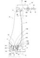
- FIG. It is sectional drawing which shows the urinal of Example 1.
- FIG. It is a perspective view which shows the urinal of Example 1.
- FIG. It is sectional drawing which shows the urinal of Example 2.
- FIG. The water discharge pattern of the urinal of Example 1 and 2 is shown, (A) is a graph based on a seasonal change, (B) is a graph based on the time change of a day.
- the water discharge device includes a spray nozzle for discharging spray-like washing water toward a first surface which is a predetermined surface of the toilet bowl, and other than the first surface And a rectifying nozzle for discharging rectified washing water toward the second surface, which is the surface of the toilet bowl portion.
- a spray nozzle for discharging spray-like washing water toward a first surface which is a predetermined surface of the toilet bowl, and other than the first surface
- a rectifying nozzle for discharging rectified washing water toward the second surface, which is the surface of the toilet bowl portion.
- the spray nozzle for example, the left and right edges of the surface of the toilet bowl that protrudes outside the toilet bowl when sprayed with washing water
- the rectified cleaning water is discharged from the rectifying nozzle. If it does in this way, wash water can be flowed satisfactorily on the whole surface of a stool part, and urine adhering to the surface of a stool part can be made to surely flow into a drain trap from an inflow port.
- the water discharging device discharges the cleaning water every time it is used, and the first mode in which the cleaning water is not discharged, the second mode in which the cleaning water is discharged every predetermined time.
- the frequency of flushing the wash water from the water spouting device is changed according to the frequency of use of the urinal and the odor that changes depending on the environment such as temperature, etc. You can plan.
- Example 1 The urinal of Example 1 is provided with the urinal main body 10, the drain trap 30, and the water discharging apparatus 50, as shown in FIG.1 and FIG.2.
- the urinal body 10 has a toilet bowl 11 and is fixed to the wall W by being locked by a hanging metal fitting (not shown).
- the urinal body 10 has an opening 12 in which the lower end of the toilet bowl 11 is opened.
- the opening 12 is connected to a drainage connection pipe 13.
- the drainage connection pipe 13 includes a storage part 14 that houses a cartridge-type drain trap 30 that is detachable continuously from the opening 12, and a drainage pipe that extends from the storage part 14 in the wall W direction and is drawn out from the wall part W. And a connecting portion 15 connected to D.
- the drain trap 30 is in the form of a cartridge and is detachably accommodated in the accommodating portion 14 of the drain connecting pipe 13 from the opening 12 of the urinal body 10. For this reason, the drain trap 30 is easily replaced when the urinal is used and the seal liquid forming the seal layer S to be described later decreases, or when urine stone accumulates too much in the drain trap 30. can do.
- the drain trap 30 has an inflow port 31, an internal flow path 32, and an outflow port 33.
- the inflow port 31 opens to the upper surface portion 34 of the drain trap 30 that is continuous with the lower surface of the toilet bowl 11.
- the internal flow path 32 is partitioned by a partition wall 35 that hangs down from the upper surface portion 34, and has a first chamber 36 ⁇ / b> A and a second chamber 36 ⁇ / b> B that communicate with each other below the lower end of the partition wall 35.
- the first chamber 36A and the second chamber 36B constitute a water seal portion 36.
- the first chamber 36 ⁇ / b> A communicates with the inflow port 31, and urine and washing water flow from the inflow port 31.
- a mixed liquid obtained by mixing urine and washing water is stored in the first chamber 36A and the second chamber 36B.
- the drain trap 30 communicates with the downstream side of the second chamber 36B and has an outflow path 37 through which the mixed liquid overflowing from the second chamber 36B flows down.
- the outflow port 33 is formed at the downstream end of the outflow passage 37 and opens at the edge of the lower surface portion 38 of the drain trap 30.
- the drain trap 30 is insoluble in water and injects a sealing liquid having a specific gravity smaller than that of the mixed liquid into the first chamber 36A, and the sealing liquid is retained so as to cover the upper surface on the upstream side of the stored mixed liquid.
- a seal layer S is formed. The sealing layer S can prevent the odor generated from the mixed liquid from diffusing to the toilet bowl 11 side.
- the water discharge device 50 includes one spray nozzle 51 that discharges spray-like washing water toward a first surface that is a central surface on the left and right sides of the toilet bowl 11, and a surface of the toilet bowl 11 other than the first surface. And two rectifying nozzles 52 for discharging rectified washing water toward the left and right second surfaces of the first surface, that is, the left and right edges of the surface of the toilet bowl 11.
- the water discharge device 50 is connected to the main water supply channel 53 via the main water supply channel 53, the open / close valve 54 provided in the main water supply channel 53, the three-way valve 55 provided at the downstream end of the main water supply channel 53, and the three-way valve 55.
- the on-off valve 54 and the three-way valve 55 are controlled to open and close by a control device (not shown).
- the spray nozzle 51 is connected to the downstream end of the first branch water channel 56A.
- the second branch water channel 56B is branched into two, and a rectifying nozzle 52 is connected to each downstream end.
- the urinal formed in this way switches the three-way valve 55 to discharge the washing water from the spray nozzle 51, and opens and closes the urinal.
- the valve 54 is opened for a set time, and pre-cleaning is performed.
- pre-cleaning since the washing water is discharged in a spray form, the first surface of the toilet bowl 11 can be wetted with a small amount of washing water, and urine is placed on the first surface of the toilet bowl 11 when the user urinates. becomes difficult to adhere.
- the three-way valve 55 is switched to discharge the washing water from the spray nozzle 51 and the rectifying nozzle 52, and the on-off valve 54 is switched. Is opened for the set time and the main cleaning is executed.
- the washing water discharged from the spray nozzle 51 and the rectifying nozzle 52 in the main washing causes the urine adhering to the surface of the toilet bowl 11 to flow into the drain trap 30 from the inflow port 31. It is less than the capacity of the water seal 36 and the water force may be weak.
- the seal layer S in the drain trap 30 is discharged downstream. hard. For this reason, the seal layer S in the drain trap 30 can be satisfactorily present for a long period of time, and odor can be prevented from diffusing to the toilet bowl 11 side.
- the washing water discharged to the toilet bowl 11 is an amount of water that allows the urine adhering to the surface of the toilet bowl 11 to flow into the drain trap 30 from the inlet 31 with a smaller amount of water than the capacity of the water seal 36. It's okay.
- the urinal adhered to the surface of the toilet bowl 11 is discharged from the inflow port 31 into the drain trap 30, the urinal discharges urine on the surface of the toilet bowl 11. Can be prevented, and urine components can be prevented from being decomposed by the action of bacteria on the surface of the stool portion 11 to generate ammonia. Moreover, since ammonia is not produced
- Example 1 can prevent the generation of odor and urine stone with a small amount of washing water.
- this urinal discharges the washing water from the spray nozzle 51 in the form of a spray
- the washing water can be sprayed on a wide range (first surface) of the toilet bowl 11 with a little washing water. 11 can flow into the drain trap 30 from the inlet 31.
- rectified washing water is discharged from the rectifying nozzle 52 toward the left and right edge portions (second surface) of the surface of the toilet bowl 11 that is difficult to spray with the spray nozzle 51. For this reason, washing water can be satisfactorily flowed over the entire surface of the toilet bowl 11, and urine adhering to the surface of the toilet bowl 11 can be reliably introduced into the drain trap 30 from the inlet 31.
- the water discharging apparatus 50 is the 1st mode which does not perform pre-cleaning and main cleaning (does not discharge cleaning water), and the 2nd mode which performs main cleaning (for example, every 30 minutes) at regular intervals (discharges cleaning water). , And every time the urinal is used, it has a third mode in which pre-cleaning and main cleaning are performed (washing water is discharged). Then, as shown in FIG. 5A, the water discharge device 50 is driven in the third mode from March to September in the year, and is driven in the first mode from October to February. Can be.
- the water discharge device 50 drives in the third mode from 6:00 in the morning to midnight in the day, and starts at midnight in the morning. Up to 6:00 can be driven in the second mode. That is, from 6:00 in the morning to midnight in the morning, since the frequency of using the urinal is high, it is easy to generate odor, such as urine often attaching to the surface of the toilet bowl 11. Driven in the third mode, from midnight in the morning to 6:00 in the morning, since the frequency of using the urinal is low, there is less chance of urine adhering to the surface of the toilet bowl 11, etc. Since it is difficult to derive, it is driven in the second mode.
- Example 2 The urinal of Example 2 is different from Example 1 in the form of a drain trap 130 as shown in FIGS. 3 and 4.
- Other configurations are the same as those of the first embodiment, and the same configurations are denoted by the same reference numerals, and detailed description thereof is omitted.
- the drain trap 130 is also in the form of a cartridge and is detachably accommodated in the accommodating portion 14 of the drain connecting pipe 13 from the opening 12 of the urinal body 10. For this reason, the drain trap 130 can be easily replaced when a float member 134 (to be described later) is damaged, or when urine stone accumulates too much in the drain trap 130.
- the drain trap 130 has an inlet 131, an internal channel 132, an outlet 133, and a float member 134.
- the inflow port 131 opens at the center of the upper surface portion 135 of the drain trap 130.
- the upper surface portion 135 of the drain trap 130 is formed with an inclined surface in which the peripheral edge portion of the inlet 131 is inclined downward toward the inlet 131.
- the internal channel 132 has a first chamber 137A and a second chamber 137B that are partitioned by a cylindrical partition wall 136 that hangs from the upper surface portion 135 around the inflow port 131 and communicates below the lower end of the partition wall 136. Yes.
- the first chamber 137A and the second chamber 137B constitute a water seal 137.
- the first chamber 137 ⁇ / b> A communicates with the inlet 131, and urine and washing water flow from the inlet 131.
- a mixed liquid obtained by mixing urine and washing water is stored in the first chamber 137A and the second chamber 137B.
- the drain trap 130 communicates with the downstream side of the second chamber 137B and has an outflow path 138 through which the mixed liquid overflowing from the second chamber 137B flows down.
- the outflow port 133 is formed at the downstream end of the outflow passage 138 and opens at the edge of the lower surface portion 139 of the drain trap 130.
- the float member 134 is housed in the first chamber 137A and has a cylindrical body 137A and a spherical upper end 134B.
- the float member 134 floats due to the buoyancy exerted by the liquid mixture stored in the water seal portion 137, and the spherical upper end portion 137 ⁇ / b> B contacts the peripheral edge of the inflow port 131 to close the inflow port 131. For this reason, it is possible to prevent the odor generated from the mixed liquid stored in the sealing part 137 from diffusing to the toilet bowl 11 side.
- the urinal formed in this way switches the three-way valve 55 to discharge the washing water from the spray nozzle 51, and opens and closes the urinal.
- the valve 54 is opened for a set time, and pre-cleaning is performed.
- pre-cleaning since the washing water is discharged in a spray form, the first surface of the toilet bowl 11 can be wetted with a small amount of washing water, and urine is placed on the first surface of the toilet bowl 11 when the user urinates. becomes difficult to adhere.
- the three-way valve 55 is switched to discharge the washing water from the spray nozzle 51 and the rectifying nozzle 52, and the on-off valve 54 is switched. Is opened for the set time and the main cleaning is executed.
- the washing water discharged from the spray nozzle 51 and the rectifying nozzle 52 in the main washing causes the urine adhering to the surface of the toilet bowl 11 to flow into the drain trap 130 from the inflow port 131. It is less than the capacity of the water seal part 137 and the water force may be weak.
- This urinal prevents the odor from diffusing to the toilet bowl 11 side because the float member 134 closes the inlet 131 even if urine stays in the water seal 137 and generates odor. be able to.
- the washing water discharged to the toilet bowl 11 is an amount of water that allows the urine adhering to the surface of the toilet bowl 11 to flow into the drain trap 130 from the inlet 131 with a smaller amount of water than the capacity of the water seal 137. It's okay.
- the urinal adhered to the surface of the toilet bowl 11 is discharged from the inflow port 131 into the drain trap 130, the urinal discharges urine on the surface of the toilet bowl 11.
- the urinal floats when the water discharging device 50 discharges washing water to the surface of the toilet bowl 11 and causes the urine adhering to the surface of the toilet bowl 11 to flow into the drain trap 130 from the inlet 131.
- the urine remaining in the upper periphery of the inlet 131 closed by the member 134 also flows into the drain trap 130 together. For this reason, urine does not remain in the upper periphery of the inlet 131 closed by the float member 134.
- the urinal of Example 2 can also prevent the generation of odor and urine stone with a small amount of washing water.
- this urinal discharges washing water from the spray nozzle 51 in the form of a spray
- the washing water can be sprayed over a wide range (first surface) of the toilet bowl 11 with a small amount of washing water. 11 can flow into the drainage trap 130 from the inlet 131.
- rectified washing water is discharged from the rectifying nozzle 52 toward the left and right edge portions (second surface) of the surface of the toilet bowl 11 that is difficult to spray with the spray nozzle 51. For this reason, washing water can be satisfactorily flowed over the entire surface of the toilet bowl 11, and urine adhering to the surface of the toilet bowl 11 can be reliably introduced into the drain trap 130 from the inlet 131.
- the present invention is not limited to the first and second embodiments described with reference to the above description and drawings.
- the following embodiments are also included in the technical scope of the present invention.
- one spray nozzle and two rectifying nozzles are provided, but it is sufficient that each of them has at least one or more.
- the pre-cleaning is executed, but the pre-cleaning may not be executed.
- the cleaning mode of the water discharger was changed from March to September and from October to February, but the period can be changed as appropriate.
- the cleaning mode of the water discharger was changed from 6:00 in the morning to 0:00 in the evening and from 0:00 in the evening to 6:00 in the morning. Can be appropriately changed.
- the water discharging device selects the third mode and the first mode to discharge the cleaning water, or selects the third mode and the second mode to discharge the cleaning water.
- the washing water may be discharged by combining three types of the first to third modes.
Landscapes
- Engineering & Computer Science (AREA)
- Health & Medical Sciences (AREA)
- Life Sciences & Earth Sciences (AREA)
- Hydrology & Water Resources (AREA)
- Public Health (AREA)
- Water Supply & Treatment (AREA)
- Environmental & Geological Engineering (AREA)
- Sanitary Device For Flush Toilet (AREA)
Abstract
臭気及び尿石の発生を少量の洗浄水によって防止することができる小便器を提供する。 小便器は、便鉢部(11)を有する小便器本体(10)と、尿及び洗浄水が流入する流入口(31)、この流入口(31)から流入した尿及び洗浄水を混合した混合液体が貯留され、水封を形成する水封部(36)を有する内部流路(32)、及び混合液体が流出する流出口(33)を有し、混合液体よりも比重が小さいシール液を水封部(36)に注入して混合液体の上流側で上面を覆うように滞留させ、混合液体から発生する臭気が便鉢部(11)側へ拡散することを防止するシール層(S)を形成しており、便鉢部(11)の下端に設けられた排水トラップ(30)と、水封部(36)の容量よりも少ない水量の洗浄水を便鉢部(11)の表面に吐水し、便鉢部(11)の表面に付着した尿を流入口(31)から排水トラップ(30)内へ流入させる吐水装置(50)とを備えている。
Description
本発明は、小便器に関するものである。
特許文献1は従来の小便器を開示している。この小便器は、便鉢部を有する小便器本体と、便鉢部の下端に設けられた排水トラップとを備えている。排水トラップは、便鉢部から尿が流入する流入口、この流入口から流入した尿が貯留され、水封を形成する水封部を有する内部流路、及び水封部から溢流した尿が流出する流出口を有している。この排水トラップは尿よりも比重が小さいシール液を水封部に注入している。ここで、「比重が小さい」とは、比重がある物質の密度(単位体積当たりの質量)と基準となる標準物質との密度との比であることから、「密度が低い」ことを言う(以下、同じ。)。つまり、排水トラップは尿よりも密度が低いシール液を水封部に注入している。これによって、水封部の上流側で尿の上面を覆うようにシール液が滞留するシール層が形成される。
この小便器は、排水トラップに尿を貯留して形成した水封によって、排水トラップより下流側から臭気や虫等が便鉢部側へ侵入することを防止することができる。また、排水トラップに貯留した尿から発生する臭気はシール層によって便鉢部側へ拡散することを防止することができる。このように、この小便器は、洗浄水を利用せずに便鉢部側へ臭気や虫等が侵入することを防止することができるため、大きな節水効果を得ることができる。
また、便鉢部から尿が流入する流入口、この流入口から流入した尿が貯留され、水封を形成する水封部を有する内部流路、水封部から溢流した尿が流出する流出口、及び水封部に貯留した尿が及ぼす浮力によって浮上し、下方から流入口の周縁に当接して流入口を閉鎖するフロート部材を有した排水トラップが知られている。つまり、この排水トラップを便鉢部の下端に設けた小便器も知られている。
この小便器も、排水トラップに尿を貯留して形成した水封によって、排水トラップより下流側から臭気や虫等が便鉢部側へ侵入することを防止することができる。また、排水トラップに貯留した尿から発生する臭気はフロート部材が流入口を閉鎖しているため便鉢部側へ拡散することを防止することができる。このように、この小便器も、洗浄水を利用せずに便鉢部側へ臭気や虫等が侵入することを防止することができるため、大きな節水効果を得ることができる。
しかし、上記した従来の小便器では、便鉢部の表面に付着した尿を能動的に流入口から排水トラップ内へ流入させる機能を有していない。このため、便鉢部の表面に尿が残留する。便鉢部の表面に残留した尿は、時間の経過とともに、臭気が発生したり、便鉢部の表面に尿石を形成したりするおそれがある。つまり、尿は、排泄された直後には臭気が発生せず、時間の経過と共にバクテリアの作用によって尿中の成分が分解してアンモニアを生成し、臭気を発生する。また、アンモニアの生成によって、pHが上昇すると尿中のカルシウムイオン等が炭酸塩、リン酸塩として析出し、尿石を形成する。尿石が形成されると、尿石が多孔質のため、様々なバクテリアや有機物の温床となり、さらに強烈な臭気を放出することになる。
また、排水トラップの水封部の容量よりも多い水量の洗浄水を便鉢部の表面に吐水する一般的な水洗式小便器が存在する。これは、使用者が排尿した後に尿が滞留する水封部内を新たな洗浄水に置換するものである。このため、この水洗式小便器は、便鉢部の表面に尿が残留することが無いが、1回の便器洗浄に2~3Lの洗浄水を消費してしまう。
本発明は、上記従来の実情に鑑みてなされたものであって、臭気及び尿石の発生を少量の洗浄水によって防止することができる小便器を提供することを解決すべき課題としている。
第1発明の小便器は、便鉢部を有する小便器本体と、
前記便鉢部から尿及び洗浄水が流入する流入口、この流入口から流入した尿及び洗浄水を混合した混合液体が貯留され、水封を形成する水封部を有する内部流路、及び前記水封部から溢流した前記混合液体が流出する流出口を有し、前記混合液体よりも比重が小さいシール液を前記水封部に注入して前記混合液体の上流側で上面を覆うように滞留させ、前記混合液体から発生する臭気が便鉢部側へ拡散することを防止するシール層を形成しており、前記便鉢部の下端に設けられた排水トラップと、
前記水封部の容量よりも少ない水量の洗浄水を前記便鉢部の表面に吐水し、前記便鉢部の表面に付着した尿を前記流入口から前記排水トラップ内へ流入させる吐水装置とを備えていることを特徴とする。
前記便鉢部から尿及び洗浄水が流入する流入口、この流入口から流入した尿及び洗浄水を混合した混合液体が貯留され、水封を形成する水封部を有する内部流路、及び前記水封部から溢流した前記混合液体が流出する流出口を有し、前記混合液体よりも比重が小さいシール液を前記水封部に注入して前記混合液体の上流側で上面を覆うように滞留させ、前記混合液体から発生する臭気が便鉢部側へ拡散することを防止するシール層を形成しており、前記便鉢部の下端に設けられた排水トラップと、
前記水封部の容量よりも少ない水量の洗浄水を前記便鉢部の表面に吐水し、前記便鉢部の表面に付着した尿を前記流入口から前記排水トラップ内へ流入させる吐水装置とを備えていることを特徴とする。
この小便器は、水封部に尿が滞留して臭気を発生しても、シール層によって臭気が便鉢部側へ拡散することを防止することができる。このため、便鉢部に吐水する洗浄水は、水封部の容量よりも少ない水量で便鉢部の表面に付着した尿を流入口から排水トラップ内へ流入させるだけの水量でよい。このように、この小便器は、便鉢部の表面に付着した尿を流入口から排水トラップ内へ流入させる必要最小限の洗浄水を吐水すれば、便鉢部の表面に尿が残留することを防止することができ、便鉢部の表面で尿の成分がバクテリアの作用によって分解され、アンモニアが生成されることを防止することができる。また、アンモニアが生成されないため、便鉢部の表面のpHの上昇も防止することができる。
したがって、第1発明の小便器は臭い及び尿石の発生を少量の洗浄水によって防止することができる。
第2発明の小便器は、便鉢部を有する小便器本体と、
前記便鉢部から尿及び洗浄水が流入する流入口、この流入口から流入した尿及び洗浄水を混合した混合液体が貯留され、水封を形成する水封部を有する内部流路、前記水封部から溢流した前記混合液体が流出する流出口、及び貯留した前記混合液体が及ぼす浮力によって浮上し、下方から前記流入口の周縁に当接して前記流入口を閉鎖するフロート部材を有しており、前記便鉢部の下端部に設けられた排水トラップと、
前記水封部の容量よりも少ない水量の洗浄水を前記便鉢部の表面に吐水し、前記便鉢部の表面に付着した尿を前記流入口から前記排水トラップ内へ流入させる吐水装置とを備えていることを特徴とする。
前記便鉢部から尿及び洗浄水が流入する流入口、この流入口から流入した尿及び洗浄水を混合した混合液体が貯留され、水封を形成する水封部を有する内部流路、前記水封部から溢流した前記混合液体が流出する流出口、及び貯留した前記混合液体が及ぼす浮力によって浮上し、下方から前記流入口の周縁に当接して前記流入口を閉鎖するフロート部材を有しており、前記便鉢部の下端部に設けられた排水トラップと、
前記水封部の容量よりも少ない水量の洗浄水を前記便鉢部の表面に吐水し、前記便鉢部の表面に付着した尿を前記流入口から前記排水トラップ内へ流入させる吐水装置とを備えていることを特徴とする。
この小便器は、水封部に尿が滞留して臭気を発生しても、フロート部材が流入口を閉鎖しているため、臭気が便鉢部側へ拡散することを防止することができる。このため、便鉢部に吐水する洗浄水は、水封部の容量よりも少ない水量で便鉢部の表面に付着した尿を流入口から排水トラップ内へ流入させるだけの水量でよい。このように、この小便器は、便鉢部の表面に付着した尿を流入口から排水トラップ内へ流入させる必要最小限の洗浄水を吐水すれば、便鉢部の表面に尿が残留することを防止することができ、便鉢部の表面で尿の成分がバクテリアの作用によって分解され、アンモニアが生成されることを防止することができる。また、アンモニアが生成されないため、便鉢部の表面のpHの上昇も防止することができる。
また、この小便器は、吐水装置が洗浄水を便鉢部の表面に吐水し、便鉢部の表面に付着した尿を流入口から排水トラップ内へ流入させる際に、フロート部材によって閉鎖した流入口の上方周辺に残留した尿も一緒に排水トラップ内へ流入する。このため、フロート部材によって閉鎖した流入口の上方周辺に尿が残留しない。
したがって、第2発明の小便器は臭い及び尿石の発生を少量の洗浄水によって防止することができる。
第1発明及び第2発明における好ましい実施の形態を説明する。
第1発明及び第2発明の小便器において、前記吐水装置は、前記便鉢部の所定の表面である第1表面に向けて噴霧状の洗浄水を吐水する噴霧ノズルと、前記第1表面以外の前記便鉢部の表面である第2表面に向けて整流状の洗浄水を吐水する整流ノズルとを有し得る。この場合、噴霧ノズルから洗浄水を噴霧状に吐水するため、少ない洗浄水で便鉢部の広い範囲に洗浄水を噴霧することができ、表面に付着した尿を流入口から排水トラップ内へ流入させることができる。また、噴霧ノズルでは噴霧し難い便鉢部の表面(例えば、噴霧ノズルで洗浄水を噴霧すると便鉢部の外側にはみ出してしまうような便鉢部の表面の左右縁部等の表面)に向けて整流ノズルから整流状の洗浄水を吐水する。このようにすれば、便鉢部の表面全体に洗浄水を良好に流すことができ、便鉢部の表面に付着した尿を確実に流入口から排水トラップ内へ流入させることができる。
第1発明及び第2発明の小便器において、前記吐水装置は、洗浄水を吐水しない第1モード、一定時間ごとに洗浄水を吐水する第2モード、及び使用される毎に洗浄水を吐水する第3モードを有し、少なくともこれら各モードの内、2つのモードを選択して洗浄水を吐水し得る。この場合、小便器の使用頻度や、温度等の環境等によって変化する臭気の発生具合に応じて吐水装置から洗浄水を吐水する頻度を変更し、臭気の発生を効率的に抑制し、節水を図ることができる。
次に、第1発明の小便器を具体化した実施例1、及び第2発明の小便器を具体化した実施例2について、図面を参照しつつ説明する。
<実施例1>
実施例1の小便器は、図1及び図2に示すように、小便器本体10と、排水トラップ30と、吐水装置50とを備えている。小便器本体10は、便鉢部11を有しており、壁部Wに図示しない吊下げ金具に係止されて固定されている。小便器本体10は、便鉢部11の下端が開口した開口部12を有している。開口部12は排水連結管13に連結されている。排水連結管13は、開口部12に連続して着脱自在なカートリッジ形態の排水トラップ30を収納する収納部14と、収納部14から壁部W方向に延びて壁部Wから引き出された排水管Dに連結する連結部15とを有している。
実施例1の小便器は、図1及び図2に示すように、小便器本体10と、排水トラップ30と、吐水装置50とを備えている。小便器本体10は、便鉢部11を有しており、壁部Wに図示しない吊下げ金具に係止されて固定されている。小便器本体10は、便鉢部11の下端が開口した開口部12を有している。開口部12は排水連結管13に連結されている。排水連結管13は、開口部12に連続して着脱自在なカートリッジ形態の排水トラップ30を収納する収納部14と、収納部14から壁部W方向に延びて壁部Wから引き出された排水管Dに連結する連結部15とを有している。
排水トラップ30は、カートリッジ形態であり、小便器本体10の開口部12から排水連結管13の収納部14に着脱自在に収納されている。このため、排水トラップ30は、小便器が使用されることによって後述するシール層Sを形成するシール液が減少したり、尿石が排水トラップ30内に堆積しすぎたりした場合に、容易に交換することができる。排水トラップ30は、流入口31、内部流路32、及び流出口33を有している。流入口31は便鉢部11の下部表面に連続した排水トラップ30の上面部34に開口している。内部流路32は、上面部34から垂下した隔壁35によって仕切られ、隔壁35の下端より下方で連通した第1室36Aと第2室36Bとを有している。第1室36Aと第2室36Bとで水封部36を構成している。第1室36Aは、流入口31に連通しており、流入口31から尿及び洗浄水が流入する。第1室36Aと第2室36Bに尿及び洗浄水を混合した混合液体が貯留される。排水トラップ30は、第2室36Bの下流側に連通し、第2室36Bから溢流した混合液体が流下する流出路37を有している。流出口33は、流出路37の下流端に形成され、排水トラップ30の下面部38の縁部に開口している。
排水トラップ30は、非溶水性であり、混合液体よりも比重が小さいシール液を第1室36Aに注入して、貯留された混合液体の上流側で上面を覆うようにシール液を滞留させてシール層Sを形成している。シール層Sは混合液体から発生する臭気が便鉢部11側へ拡散することを防止することができる。
吐水装置50は、便鉢部11の左右中央の表面である第1表面に向けて噴霧状の洗浄水を吐水する1個の噴霧ノズル51と、(第1表面以外の便鉢部11の表面である)第1表面の左右の第2表面、つまり便鉢部11の表面の左右縁部に向けて整流状の洗浄水を吐水する2個の整流ノズル52とを有している。
吐水装置50は、給水源に連通した主給水路53と、主給水路53に設けた開閉弁54と、主給水路53の下流端に設けた三方弁55と、三方弁55を介して主給水路53に連通した第1分岐水路56A及び第2分岐水路56Bとを有している。開閉弁54と三方弁55は、図示しない制御装置によって開閉制御されている。第1分岐水路56Aの下流端に噴霧ノズル51が連結している。第2分岐水路56Bは2つに分岐されており、夫々の下流端に整流ノズル52が連結している。
このように形成された小便器は、使用者が小便器の前に近づいたことを図示しない人体検知センサーが検知すると、噴霧ノズル51から洗浄水を吐水するように三方弁55を切り替えて、開閉弁54を設定時間の間、開弁し、前洗浄を実行する。前洗浄時において、噴霧状に洗浄水を吐水するため、少ない洗浄水で便鉢部11の第1表面を濡らすことができ、使用者が排尿した際に便鉢部11の第1表面に尿が付着し難くなる。
そして、使用者が排尿した後に小便器の前から立ち去ったことを人体検知センサーが検知すると、噴霧ノズル51と整流ノズル52とから洗浄水を吐水するように三方弁55を切り替えて、開閉弁54を設定時間の間、開弁し、本洗浄を実行する。本洗浄で噴霧ノズル51と整流ノズル52とから吐水する洗浄水は、便鉢部11の表面に付着した尿を流入口31から排水トラップ30内へ流入させるものであり、水量は排水トラップ30の水封部36の容量よりも少なく、水勢が弱くてよい。このように、本洗浄の際に排水トラップ30の流入口31から第1室36Aに流入する洗浄水の水量が少なく、水勢も弱いため、排水トラップ30内のシール層Sが下流側に排出され難い。このため、排水トラップ30内のシール層Sが長期間、良好に存在し、臭気が便鉢部11側へ拡散することを防止することができる。
この小便器は、水封部36に尿が滞留して臭気を発生しても、シール層Sによって臭気が便鉢部11側へ拡散することを防止することができる。このため、便鉢部11に吐水する洗浄水は、水封部36の容量よりも少ない水量で便鉢部11の表面に付着した尿を流入口31から排水トラップ30内へ流入させるだけの水量でよい。このように、この小便器は、便鉢部11の表面に付着した尿を流入口31から排水トラップ30内へ流入させる必要最小限の洗浄水を吐水すれば、便鉢部11の表面に尿が残留することを防止することができ、便鉢部11の表面で尿の成分がバクテリアの作用によって分解され、アンモニアが生成されることを防止することができる。また、アンモニアが生成されないため、便鉢部11の表面のpHの上昇も防止することができる。
したがって、実施例1の小便器は臭い及び尿石の発生を少量の洗浄水によって防止することができる。
また、この小便器は、噴霧ノズル51から洗浄水を噴霧状に吐水するため、少ない洗浄水で便鉢部11の広い範囲(第1表面)に洗浄水を噴霧することができ、便鉢部11の表面に付着した尿を流入口31から排水トラップ30内へ流入させることができる。また、噴霧ノズル51では噴霧し難い便鉢部11の表面の左右縁部(第2表面)に向けて整流ノズル52から整流状の洗浄水を吐水する。このため、便鉢部11の表面全体に洗浄水を良好に流すことができ、便鉢部11の表面に付着した尿を確実に流入口31から排水トラップ30内へ流入させることができる。
また、吐水装置50は、前洗浄及び本洗浄をしない(洗浄水を吐水しない)第1モード、一定時間ごと(例えば、30分ごと)に本洗浄を行う(洗浄水を吐水する)第2モード、及び小便器が使用される毎に前洗浄及び本洗浄を行う(洗浄水を吐水する)第3モードを有している。そして、吐水装置50は、図5(A)に示すように、1年の内、3月から9月までを第3モードで駆動し、10月から2月までを第1モードで駆動するようにすることができる。つまり、3月から9月までは、比較的、気温が高いため、便鉢部11の表面に付着した尿の乾燥が早くなる等、臭気が発生し易くなることから、第3モードで駆動し、10月から2月までは、比較的、気温が低いため、便鉢部11の表面に付着した尿の乾燥が遅い等、臭気が発生し難くなることから第1モードで駆動する。
また、吐水装置50は、図5(B)に示すように、1日の内、朝の6:00から夜中の0:00までを第3モードで駆動し、夜中の0:00から朝の6:00までを第2モードで駆動することができる。つまり、朝の6:00から夜中の0:00までは、小便器を利用する頻度が多いため、便鉢部11の表面に尿が付着する機会が多い等、臭気が発生し易くなることから、第3モードで駆動し、夜中の0:00から朝の6:00までは、小便器を利用する頻度が少ないため、便鉢部11の表面に尿が付着する機会が少ない等、臭気が派生し難くなることから第2モードで駆動する。
<実施例2>
実施例2の小便器は、図3及び図4に示すように、排水トラップ130の形態が実施例1と相違する。他の構成は、実施例1と同様であり、同一の構成は同一の符号を付し、詳細な説明を省略する。
実施例2の小便器は、図3及び図4に示すように、排水トラップ130の形態が実施例1と相違する。他の構成は、実施例1と同様であり、同一の構成は同一の符号を付し、詳細な説明を省略する。
排水トラップ130も、カートリッジ形態であり、小便器本体10の開口部12から排水連結管13の収納部14に着脱自在に収納されている。このため、排水トラップ130は、後述するフロート部材134が損傷したり、尿石が排水トラップ130内に堆積しすぎたりした場合に、容易に交換することができる。排水トラップ130は、流入口131、内部流路132、流出口133、及びフロート部材134を有している。流入口131は排水トラップ130の上面部135の中央に開口している。排水トラップ130の上面部135は流入口131の周縁部が流入口131に向けて下方に傾斜した傾斜面で形成されている。内部流路132は、流入口131の周りに上面部135から垂下した円筒状の隔壁136によって仕切られ、隔壁136の下端より下方で連通した第1室137Aと第2室137Bとを有している。第1室137Aと第2室137Bとで水封部137を構成している。第1室137Aは、流入口131に連通しており、流入口131から尿及び洗浄水が流入する。第1室137Aと第2室137Bに尿及び洗浄水を混合した混合液体が貯留される。排水トラップ130は、第2室137Bの下流側に連通し、第2室137Bから溢流した混合液体が流下する流出路138を有している。流出口133は、流出路138の下流端に形成され、排水トラップ130の下面部139の縁部に開口している。
フロート部材134は、第1室137A内に収納されており、円柱状の胴部137Aと球面状の上端部134Bとを有している。フロート部材134は、水封部137に貯留した混合液体が及ぼす浮力によって浮上し、球面状の上端部137Bが流入口131の周縁に当接して流入口131を閉鎖している。このため、封水部137に貯留した混合液体から発生する臭気が便鉢部11側へ拡散することを防止することができる。
このように形成された小便器は、使用者が小便器の前に近づいたことを図示しない人体検知センサーが検知すると、噴霧ノズル51から洗浄水を吐水するように三方弁55を切り替えて、開閉弁54を設定時間の間、開弁し、前洗浄を実行する。前洗浄時において、噴霧状に洗浄水を吐水するため、少ない洗浄水で便鉢部11の第1表面を濡らすことができ、使用者が排尿した際に便鉢部11の第1表面に尿が付着し難くなる。
そして、使用者が排尿した後に小便器の前から立ち去ったことを人体検知センサーが検知すると、噴霧ノズル51と整流ノズル52とから洗浄水を吐水するように三方弁55を切り替えて、開閉弁54を設定時間の間、開弁し、本洗浄を実行する。本洗浄で噴霧ノズル51と整流ノズル52とから吐水する洗浄水は、便鉢部11の表面に付着した尿を流入口131から排水トラップ130内へ流入させるものであり、水量は排水トラップ130の水封部137の容量よりも少なく、水勢が弱くてよい。
この小便器は、水封部137に尿が滞留して臭気を発生しても、フロート部材134が流入口131を閉鎖しているため、臭気が便鉢部11側へ拡散することを防止することができる。このため、便鉢部11に吐水する洗浄水は、水封部137の容量よりも少ない水量で便鉢部11の表面に付着した尿を流入口131から排水トラップ130内へ流入させるだけの水量でよい。このように、この小便器は、便鉢部11の表面に付着した尿を流入口131から排水トラップ130内へ流入させる必要最小限の洗浄水を吐水すれば、便鉢部11の表面に尿が残留することを防止することができ、便鉢部11の表面で尿の成分がバクテリアの作用によって分解され、アンモニアが生成されることを防止することができる。また、アンモニアが生成されないため、便鉢部11の表面のpHの上昇も防止することができる。
また、この小便器は、吐水装置50が洗浄水を便鉢部11の表面に吐水し、便鉢部11の表面に付着した尿を流入口131から排水トラップ130内へ流入させる際に、フロート部材134によって閉鎖した流入口131の上方周辺に残留した尿も一緒に排水トラップ130内へ流入する。このため、フロート部材134によって閉鎖した流入口131の上方周辺に尿が残留しない。
したがって、実施例2の小便器も臭い及び尿石の発生を少量の洗浄水によって防止することができる。
また、この小便器は、噴霧ノズル51から洗浄水を噴霧状に吐水するため、少ない洗浄水で便鉢部11の広い範囲(第1表面)に洗浄水を噴霧することができ、便鉢部11の表面に付着した尿を流入口131から排水トラップ130内へ流入させることができる。また、噴霧ノズル51では噴霧し難い便鉢部11の表面の左右縁部(第2表面)に向けて整流ノズル52から整流状の洗浄水を吐水する。このため、便鉢部11の表面全体に洗浄水を良好に流すことができ、便鉢部11の表面に付着した尿を確実に流入口131から排水トラップ130内へ流入させることができる。
本発明は上記記述及び図面によって説明した実施例1及び2に限定されるものではなく、例えば次のような実施例も本発明の技術的範囲に含まれる。
(1)実施例1及び2では、噴霧状に洗浄水を吐水する噴霧ノズルと、整流状に洗浄水を吐水する整流ノズルとを有していたが、他の状態に洗浄水を吐水するノズルを有してもよい。
(2)実施例1及び2では、1個の噴霧ノズルと2個の整流ノズルとを有していたが、噴霧ノズル又は整流ノズルのどちらか一方を有していればよい。この場合、同一種類のノズルを複数個有していてもよい。
(3)実施例1及び2では、1個の噴霧ノズルと2個の整流ノズルとを有していたが、夫々が少なくとも一つ以上有していればよい。
(4)実施例1及び2では、前洗浄を実行したが、前洗浄を実行しなくてもよい。
(5)実施例1及び2では、3月から9月までと、10月から2月までとで吐水装置の洗浄モードを変更したが、その期間は適宜変更することができる。
(6)実施例1及び2では、朝の6:00から夜中の0:00までと、夜中の0:00から朝の6:00までとで吐水装置の洗浄モードを変更したが、その時間は適宜変更することができる。
(7)実施例1及び2では、吐水装置が第3モードと第1モードとを選択して洗浄水を吐水したり、第3モードと第2モードとを選択して洗浄水を吐水したりしたが、第1~第3モードの三種類を組み合わせて洗浄水を吐水してもよい。
(1)実施例1及び2では、噴霧状に洗浄水を吐水する噴霧ノズルと、整流状に洗浄水を吐水する整流ノズルとを有していたが、他の状態に洗浄水を吐水するノズルを有してもよい。
(2)実施例1及び2では、1個の噴霧ノズルと2個の整流ノズルとを有していたが、噴霧ノズル又は整流ノズルのどちらか一方を有していればよい。この場合、同一種類のノズルを複数個有していてもよい。
(3)実施例1及び2では、1個の噴霧ノズルと2個の整流ノズルとを有していたが、夫々が少なくとも一つ以上有していればよい。
(4)実施例1及び2では、前洗浄を実行したが、前洗浄を実行しなくてもよい。
(5)実施例1及び2では、3月から9月までと、10月から2月までとで吐水装置の洗浄モードを変更したが、その期間は適宜変更することができる。
(6)実施例1及び2では、朝の6:00から夜中の0:00までと、夜中の0:00から朝の6:00までとで吐水装置の洗浄モードを変更したが、その時間は適宜変更することができる。
(7)実施例1及び2では、吐水装置が第3モードと第1モードとを選択して洗浄水を吐水したり、第3モードと第2モードとを選択して洗浄水を吐水したりしたが、第1~第3モードの三種類を組み合わせて洗浄水を吐水してもよい。
10…小便器本体
11…便鉢部
30…排水トラップ
31…流入口
32…内部流路
33…流出口
36…水封部
50…吐水装置
51…噴霧ノズル
52…整流ノズル
S…シール層
130…排水トラップ
131…流入口
132…内部流路
133…流出口
134…フロート部材
137…水封部
11…便鉢部
30…排水トラップ
31…流入口
32…内部流路
33…流出口
36…水封部
50…吐水装置
51…噴霧ノズル
52…整流ノズル
S…シール層
130…排水トラップ
131…流入口
132…内部流路
133…流出口
134…フロート部材
137…水封部
Claims (4)
- 便鉢部を有する小便器本体と、
前記便鉢部から尿及び洗浄水が流入する流入口、この流入口から流入した尿及び洗浄水を混合した混合液体が貯留され、水封を形成する水封部を有する内部流路、及び前記水封部から溢流した前記混合液体が流出する流出口を有し、前記混合液体よりも比重が小さいシール液を前記水封部に注入して前記混合液体の上流側で上面を覆うように滞留させ、前記混合液体から発生する臭気が便鉢部側へ拡散することを防止するシール層を形成しており、前記便鉢部の下端に設けられた排水トラップと、
前記水封部の容量よりも少ない水量の洗浄水を前記便鉢部の表面に吐水し、前記便鉢部の表面に付着した尿を前記流入口から前記排水トラップ内へ流入させる吐水装置とを備えていることを特徴とする小便器。 - 便鉢部を有する小便器本体と、
前記便鉢部から尿及び洗浄水が流入する流入口、この流入口から流入した尿及び洗浄水を混合した混合液体が貯留され、水封を形成する水封部を有する内部流路、前記水封部から溢流した前記混合液体が流出する流出口、及び貯留した前記混合液体が及ぼす浮力によって浮上し、下方から前記流入口の周縁に当接して前記流入口を閉鎖するフロート部材を有しており、前記便鉢部の下端部に設けられた排水トラップと、
前記水封部の容量よりも少ない水量の洗浄水を前記便鉢部の表面に吐水し、前記便鉢部の表面に付着した尿を前記流入口から前記排水トラップ内へ流入させる吐水装置とを備えていることを特徴とする小便器。 - 前記吐水装置は、前記便鉢部の所定の表面である第1表面に向けて噴霧状の洗浄水を吐水する噴霧ノズルと、前記第1表面以外の前記便鉢部の表面である第2表面に向けて整流状の洗浄水を吐水する整流ノズルとを有していることを特徴とする請求項1又は2記載の小便器。
- 前記吐水装置は、洗浄水を吐水しない第1モード、一定時間ごとに洗浄水を吐水する第2モード、及び使用される毎に洗浄水を吐水する第3モードを有し、少なくともこれら各モードの内、2つのモードを選択して洗浄水を吐水することを特徴とする請求項1乃至3のいずれか1項記載の小便器。
Applications Claiming Priority (4)
| Application Number | Priority Date | Filing Date | Title |
|---|---|---|---|
| JP2013087398A JP6049197B2 (ja) | 2013-04-18 | 2013-04-18 | 小便器 |
| JP2013-087398 | 2013-04-18 | ||
| JP2013087397A JP6049196B2 (ja) | 2013-04-18 | 2013-04-18 | 小便器 |
| JP2013-087397 | 2013-04-18 |
Publications (1)
| Publication Number | Publication Date |
|---|---|
| WO2014171252A1 true WO2014171252A1 (ja) | 2014-10-23 |
Family
ID=51731209
Family Applications (1)
| Application Number | Title | Priority Date | Filing Date |
|---|---|---|---|
| PCT/JP2014/057398 Ceased WO2014171252A1 (ja) | 2013-04-18 | 2014-03-18 | 小便器 |
Country Status (1)
| Country | Link |
|---|---|
| WO (1) | WO2014171252A1 (ja) |
Citations (3)
| Publication number | Priority date | Publication date | Assignee | Title |
|---|---|---|---|---|
| JPH0718718A (ja) * | 1993-06-30 | 1995-01-20 | Kimura Giken:Kk | 小便器用洗滌システム |
| JP2002513667A (ja) * | 1998-05-05 | 2002-05-14 | ケラー・ハンス | 尿器用の防臭トラップ |
| JP2012188866A (ja) * | 2011-03-10 | 2012-10-04 | Lixil Corp | 小便器用排水トラップ及びこれを備えた小便器 |
-
2014
- 2014-03-18 WO PCT/JP2014/057398 patent/WO2014171252A1/ja not_active Ceased
Patent Citations (3)
| Publication number | Priority date | Publication date | Assignee | Title |
|---|---|---|---|---|
| JPH0718718A (ja) * | 1993-06-30 | 1995-01-20 | Kimura Giken:Kk | 小便器用洗滌システム |
| JP2002513667A (ja) * | 1998-05-05 | 2002-05-14 | ケラー・ハンス | 尿器用の防臭トラップ |
| JP2012188866A (ja) * | 2011-03-10 | 2012-10-04 | Lixil Corp | 小便器用排水トラップ及びこれを備えた小便器 |
Similar Documents
| Publication | Publication Date | Title |
|---|---|---|
| US8234723B2 (en) | Method and apparatus for delivering a urinal cleanser and trap sealant | |
| JP2020023877A (ja) | 衛生陶器洗浄システム | |
| JP6049197B2 (ja) | 小便器 | |
| JP5120770B2 (ja) | 衛生設備器具 | |
| JP6540937B2 (ja) | 小便器 | |
| KR101816779B1 (ko) | 양변기용 세정제 자동 배출장치 | |
| TWI588329B (zh) | Urinal device | |
| JP6049196B2 (ja) | 小便器 | |
| JP2013087580A (ja) | 小便器 | |
| CN201507015U (zh) | 马桶洁厕剂的容置结构 | |
| WO2014171252A1 (ja) | 小便器 | |
| CN201546298U (zh) | 一种具有省水效果的马桶洁厕剂的容置结构 | |
| KR100843616B1 (ko) | 절수 및 재활용 위생 세면대 | |
| KR20200136682A (ko) | 소변기 | |
| KR20050035530A (ko) | 저비중세척액을 사용하는 수세식변기 | |
| KR20160033487A (ko) | 냄새 없는 절수형 소변기 | |
| KR102894824B1 (ko) | 공동주택의 변기 시공방법 및 이에 의해 제작된 변기 시공구조 | |
| US8839465B2 (en) | Toilet cleaning system | |
| KR100711611B1 (ko) | 세면수를 활용하는 양변기 시스템 | |
| RU2141240C1 (ru) | Биде-комби | |
| JP4017849B2 (ja) | 水洗便器装置 | |
| CN212984089U (zh) | 一种向便器加注功能液的机构及便器 | |
| KR200291585Y1 (ko) | 간이수세식 좌변기의 거품분산 공급 구조 | |
| KR200267756Y1 (ko) | 수세식 변기용 청정제 투입장치 | |
| WO2006001577A1 (en) | Energy saving toilet bowl system recycling wash water |
Legal Events
| Date | Code | Title | Description |
|---|---|---|---|
| 121 | Ep: the epo has been informed by wipo that ep was designated in this application |
Ref document number: 14784783 Country of ref document: EP Kind code of ref document: A1 |
|
| NENP | Non-entry into the national phase |
Ref country code: DE |
|
| 122 | Ep: pct application non-entry in european phase |
Ref document number: 14784783 Country of ref document: EP Kind code of ref document: A1 |