WO2014163139A1 - 基地局、ユーザ端末、及び通信制御方法 - Google Patents
基地局、ユーザ端末、及び通信制御方法 Download PDFInfo
- Publication number
- WO2014163139A1 WO2014163139A1 PCT/JP2014/059831 JP2014059831W WO2014163139A1 WO 2014163139 A1 WO2014163139 A1 WO 2014163139A1 JP 2014059831 W JP2014059831 W JP 2014059831W WO 2014163139 A1 WO2014163139 A1 WO 2014163139A1
- Authority
- WO
- WIPO (PCT)
- Prior art keywords
- base station
- pattern
- user terminal
- transmission
- communication
- Prior art date
- Legal status (The legal status is an assumption and is not a legal conclusion. Google has not performed a legal analysis and makes no representation as to the accuracy of the status listed.)
- Ceased
Links
Images


Classifications
-
- H—ELECTRICITY
- H04—ELECTRIC COMMUNICATION TECHNIQUE
- H04W—WIRELESS COMMUNICATION NETWORKS
- H04W28/00—Network traffic management; Network resource management
- H04W28/16—Central resource management; Negotiation of resources or communication parameters, e.g. negotiating bandwidth or QoS [Quality of Service]
-
- H—ELECTRICITY
- H04—ELECTRIC COMMUNICATION TECHNIQUE
- H04W—WIRELESS COMMUNICATION NETWORKS
- H04W52/00—Power management, e.g. Transmission Power Control [TPC] or power classes
- H04W52/02—Power saving arrangements
- H04W52/0203—Power saving arrangements in the radio access network or backbone network of wireless communication networks
- H04W52/0206—Power saving arrangements in the radio access network or backbone network of wireless communication networks in access points, e.g. base stations
-
- H—ELECTRICITY
- H04—ELECTRIC COMMUNICATION TECHNIQUE
- H04W—WIRELESS COMMUNICATION NETWORKS
- H04W76/00—Connection management
- H04W76/20—Manipulation of established connections
- H04W76/28—Discontinuous transmission [DTX]; Discontinuous reception [DRX]
-
- H—ELECTRICITY
- H04—ELECTRIC COMMUNICATION TECHNIQUE
- H04W—WIRELESS COMMUNICATION NETWORKS
- H04W52/00—Power management, e.g. Transmission Power Control [TPC] or power classes
- H04W52/04—Transmission power control [TPC]
- H04W52/38—TPC being performed in particular situations
- H04W52/44—TPC being performed in particular situations in connection with interruption of transmission
-
- H—ELECTRICITY
- H04—ELECTRIC COMMUNICATION TECHNIQUE
- H04W—WIRELESS COMMUNICATION NETWORKS
- H04W88/00—Devices specially adapted for wireless communication networks, e.g. terminals, base stations or access point devices
- H04W88/08—Access point devices
-
- Y—GENERAL TAGGING OF NEW TECHNOLOGICAL DEVELOPMENTS; GENERAL TAGGING OF CROSS-SECTIONAL TECHNOLOGIES SPANNING OVER SEVERAL SECTIONS OF THE IPC; TECHNICAL SUBJECTS COVERED BY FORMER USPC CROSS-REFERENCE ART COLLECTIONS [XRACs] AND DIGESTS
- Y02—TECHNOLOGIES OR APPLICATIONS FOR MITIGATION OR ADAPTATION AGAINST CLIMATE CHANGE
- Y02D—CLIMATE CHANGE MITIGATION TECHNOLOGIES IN INFORMATION AND COMMUNICATION TECHNOLOGIES [ICT], I.E. INFORMATION AND COMMUNICATION TECHNOLOGIES AIMING AT THE REDUCTION OF THEIR OWN ENERGY USE
- Y02D30/00—Reducing energy consumption in communication networks
- Y02D30/70—Reducing energy consumption in communication networks in wireless communication networks
Definitions
- the present invention relates to a base station, a user terminal, and a communication control method used in a mobile communication system.
- NCT New Carrier Type
- NCT cell-specific reference signal
- LCDT Legacy Carrier Type
- power consumption of the base station can be reduced (that is, power saving) by stopping the operation of the transmission unit of the base station in a period in which CRS is not transmitted. .
- the present invention provides a base station, a user terminal, and a communication control method that can realize power saving while suppressing deterioration in service quality.
- the base station manages cells.
- the base station includes a transmitter that transmits a radio signal, a controller that performs intermittent transmission that intermittently activates the transmitter, and a receiver that receives a communication request from a user terminal in the cell.
- the control unit when performing the intermittent transmission, temporarily changes the activation pattern of the transmission unit in response to reception of the communication request, and displays the pattern information indicating the changed activation pattern in the user terminal Notify
- the user terminal is located in a cell of a base station having a transmission unit that transmits a radio signal.
- the base station performs intermittent transmission that intermittently activates the transmission unit.
- the user terminal notifies the base station of pattern information indicating the changed activation pattern, and a control unit that issues a communication request to the base station so as to temporarily change the activation pattern of the transmission unit And a receiving unit that performs reception from the base station based on the pattern information.
- a communication control method includes a step in which a base station having a transmission unit that transmits a radio signal performs intermittent transmission to intermittently activate the transmission unit, and the base station is a user in its own cell.
- the present invention it is possible to provide a base station, a user terminal, and a communication control method that can realize power saving while suppressing deterioration in service quality.
- FIG. 10 is a diagram illustrating a RAR message configuration according to a first modification. It is an operation
- the base station manages cells.
- the base station includes a transmitter that transmits a radio signal, a controller that performs intermittent transmission that intermittently activates the transmitter, and a receiver that receives a communication request from a user terminal in the cell.
- the control unit when performing the intermittent transmission, temporarily changes the activation pattern of the transmission unit in response to reception of the communication request, and displays the pattern information indicating the changed activation pattern in the user terminal Notify
- the control unit when the activation pattern is changed in response to reception of the communication request, sets the changed activation pattern based on information on communication performed by the user terminal.
- the information related to the communication is information indicating the QoS required for the communication or information indicating the data amount of the communication.
- control unit includes the pattern information in an RRC message or a random access response and notifies the user terminal.
- control unit activates the transmission unit at a first period in the intermittent transmission.
- the control unit changes to the activation pattern having a second cycle shorter than the first cycle in response to reception of the communication request.
- the pattern information includes at least one of information indicating the second period, information indicating an activation time when the transmission unit is activated, and an offset value that determines a timing at which the transmission unit is activated. Contains one.
- the control unit when performing the intermittent transmission, cancels the intermittent transmission and starts normal transmission based on reception status of communication requests from a plurality of user terminals in the cell. .
- the user terminal is located in a cell of a base station having a transmission unit that transmits a radio signal.
- the base station performs intermittent transmission that intermittently activates the transmission unit.
- the user terminal notifies the base station of pattern information indicating the changed activation pattern, and a control unit that issues a communication request to the base station so as to temporarily change the activation pattern of the transmission unit And a receiving unit that performs reception from the base station based on the pattern information.
- the pattern information is included in an RRC message or a random access response from the base station.
- the communication control method includes a step in which a base station having a transmission unit that transmits a radio signal performs intermittent transmission that intermittently activates the transmission unit, and the base station from a user terminal in its own cell Receiving the communication request, a step in which the base station temporarily changes the activation pattern of the transmission unit in response to reception of the communication request, and the base station indicates the activation pattern after the change. Notifying the user terminal of pattern information.
- FIG. 1 is a configuration diagram of an LTE system according to the present embodiment.
- the LTE system includes a plurality of UEs (User Equipment) 100, an E-UTRAN (Evolved Universal Terrestrial Radio Access Network) 10, and an EPC (Evolved Packet Core) 20.
- the E-UTRAN 10 corresponds to a radio access network
- the EPC 20 corresponds to a core network.
- the E-UTRAN 10 and the EPC 20 constitute an LTE system network.
- the UE 100 is a mobile communication device, and performs wireless communication with a connection destination cell (serving cell).
- UE100 is corresponded to a user terminal.
- the E-UTRAN 10 includes a plurality of eNBs 200 (evolved Node-B).
- the eNB 200 corresponds to a base station.
- the eNB 200 manages one or a plurality of cells, and performs radio communication with the UE 100 that has established a connection with the own cell.
- “cell” is used as a term indicating a minimum unit of a radio communication area, and is also used as a term indicating a function of performing radio communication with the UE 100.
- the eNB 200 has, for example, a radio resource management (RRM) function, a user data routing function, and a measurement control function for mobility control and scheduling.
- RRM radio resource management
- the EPC 20 includes a plurality of MME (Mobility Management Entity) / S-GW (Serving-Gateway) 300.
- MME Mobility Management Entity
- S-GW Serving-Gateway 300.
- the MME is a network node that performs various types of mobility control for the UE 100, and corresponds to a control station.
- the S-GW is a network node that performs transfer control of user data, and corresponds to an exchange.
- the eNB 200 is connected to each other via the X2 interface.
- the eNB 200 is connected to the MME / S-GW 300 via the S1 interface.
- FIG. 2 is a block diagram of the UE 100.
- the UE 100 includes a plurality of antennas 101, a radio transceiver 110, a user interface 120, a GNSS (Global Navigation Satellite System) receiver 130, a battery 140, a memory 150, a processor 160, Have.
- the memory 150 and the processor 160 constitute a terminal side control unit.
- the UE 100 may not have the GNSS receiver 130.
- the memory 150 may be integrated with the processor 160, and this set (that is, a chip set) may be used as the processor 160 'that constitutes the terminal side control unit.
- Radio transceiver 110 includes a transmission unit 111 that converts a baseband signal (transmission signal) output from processor 160 into a radio signal and transmits the radio signal from a plurality of antennas 101.
- the radio transceiver 110 includes a reception unit 112 that converts radio signals received by the plurality of antennas 101 into baseband signals (reception signals) and outputs the baseband signals to the processor 160.
- the user interface 120 is an interface with a user who owns the UE 100, and includes, for example, a display, a microphone, a speaker, and various buttons.
- the user interface 120 receives an operation from the user and outputs a signal indicating the content of the operation to the processor 160.
- the GNSS receiver 130 receives a GNSS signal and outputs the received signal to the processor 160 in order to obtain location information indicating the geographical location of the UE 100.
- the battery 140 stores power to be supplied to each block of the UE 100.
- the memory 150 stores a program executed by the processor 160 and information used for processing by the processor 160.
- the processor 160 performs signal processing such as modulation / demodulation and encoding / decoding of the baseband signal.
- the processor 160 executes various programs by executing programs stored in the memory 150. Further, the processor 160 executes various controls and various communication protocols described later.
- the processor 160 may include a codec that performs encoding / decoding of an audio / video signal.
- FIG. 3 is a block diagram of the eNB 200.
- the eNB 200 includes a plurality of antennas 201, a radio transceiver 210, a network interface 220, a memory 230, and a processor 240.
- the memory 230 and the processor 240 constitute a base station side control unit.
- the memory 230 may be integrated with the processor 240, and this set (that is, a chip set) may be used as a processor constituting the base station side control unit.
- the plurality of antennas 201 and the wireless transceiver 210 are used for transmitting and receiving wireless signals.
- the radio transceiver 210 includes a transmission unit 211 that converts a baseband signal (transmission signal) output from the processor 240 into a radio signal and transmits the radio signal from the plurality of antennas 201.
- the radio transceiver 210 includes a reception unit 212 that converts radio signals received by the plurality of antennas 201 into baseband signals (reception signals) and outputs the baseband signals to the processor 240.
- the network interface 220 is connected to the neighboring eNB 200 via the X2 interface and is connected to the MME / S-GW 300 via the S1 interface.
- the network interface 220 is used for communication performed on the X2 interface and communication performed on the S1 interface.
- the memory 230 stores a program executed by the processor 240 and information used for processing by the processor 240.
- the processor 240 performs signal processing such as modulation / demodulation and encoding / decoding of the baseband signal.
- the processor 240 executes programs stored in the memory 230 to perform various controls. Further, the processor 240 executes various controls and various communication protocols described later.
- FIG. 4 is a protocol stack diagram of a radio interface in the LTE system. As shown in FIG. 4, the radio interface protocol is divided into layers 1 to 3 of the OSI reference model, and layer 1 is a physical (PHY) layer. Layer 2 includes a MAC (Media Access Control) layer, an RLC (Radio Link Control) layer, and a PDCP (Packet Data Convergence Protocol) layer. Layer 3 includes an RRC (Radio Resource Control) layer.
- PHY Physical
- Layer 2 includes a MAC (Media Access Control) layer, an RLC (Radio Link Control) layer, and a PDCP (Packet Data Convergence Protocol) layer.
- Layer 3 includes an RRC (Radio Resource Control) layer.
- RRC Radio Resource Control
- the physical layer performs encoding / decoding, modulation / demodulation, antenna mapping / demapping, and resource mapping / demapping. Data is transmitted between the physical layer of the UE 100 and the physical layer of the eNB 200 via a physical channel.
- the MAC layer performs data priority control, retransmission processing by hybrid ARQ (HARQ), and the like. Data is transmitted via the transport channel between the MAC layer of the UE 100 and the MAC layer of the eNB 200.
- the MAC layer of the eNB 200 includes a scheduler that determines uplink / downlink transport formats (transport block size, modulation / coding scheme (MCS)) and allocated resource blocks.
- MCS modulation / coding scheme
- the RLC layer transmits data to the RLC layer on the receiving side using the functions of the MAC layer and the physical layer. Data is transmitted between the RLC layer of the UE 100 and the RLC layer of the eNB 200 via a logical channel.
- the PDCP layer performs header compression / decompression and encryption / decryption.
- the RRC layer is defined only in the control plane. Control messages (RRC messages) for various settings are transmitted between the RRC layer of the UE 100 and the RRC layer of the eNB 200.
- the RRC layer controls the logical channel, the transport channel, and the physical channel according to establishment, re-establishment, and release of the radio bearer.
- RRC connected state When there is an RRC connection between the RRC of the UE 100 and the RRC of the eNB 200, the UE 100 is in a connected state (RRC connected state). Otherwise, the UE 100 is in an idle state (RRC idle state).
- the NAS (Non-Access Stratum) layer located above the RRC layer performs session management and mobility management.
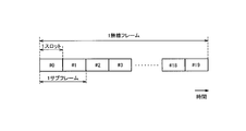
- FIG. 5 is a configuration diagram of a radio frame used in the LTE system.
- OFDMA Orthogonal Frequency Division Multiplexing Access
- SC-FDMA Single Carrier Frequency Multiple Access
- the radio frame is composed of 10 subframes arranged in the time direction, and each subframe is composed of two slots arranged in the time direction.
- the length of each subframe is 1 ms, and the length of each slot is 0.5 ms.
- Each subframe includes a plurality of resource blocks (RB) in the frequency direction and includes a plurality of symbols in the time direction.
- the resource block includes a plurality of subcarriers in the frequency direction.
- a radio resource unit configured by one subcarrier and one symbol is referred to as a resource element (RE).
- frequency resources can be specified by resource blocks, and time resources can be specified by subframes (or slots).
- NCT New Carrier Type
- NCT New Carrier Type
- FIG. 6 is a diagram for explaining NCT in comparison with a conventional carrier structure (LCT: Legacy Carrier Type).
- the section of the first few symbols of each subframe is a control region mainly used as a physical downlink control channel (PDCCH) for transmitting a control signal. Further, the remaining section of each subframe is a data area mainly used as a physical downlink shared channel (PDSCH) for transmitting user data (data signal).
- PDCH physical downlink control channel
- PDSCH physical downlink shared channel
- the PDCCH transmits a control signal.
- the control signal includes, for example, uplink SI (Scheduling Information), downlink SI, and TPC bits.
- the uplink SI is information indicating allocation of uplink radio resources
- the downlink SI is information indicating allocation of downlink radio resources.
- the TPC bit is information instructing increase / decrease in uplink transmission power. These pieces of information are referred to as downlink control information (DCI).
- DCI downlink control information
- the PDSCH transmits control signals and / or data signals.
- the downlink data area may be allocated only to the data signal, or may be allocated so that the data signal and the control signal are multiplexed.
- a cell-specific reference signal (CRS) and a channel state information reference signal (CSI-RS) are distributed.
- CRS and CSI-RS are configured by a predetermined orthogonal signal sequence.
- LCT the CRS is provided in all subframes in the time axis direction.
- the CRS is a signal used by the UE 100 for downlink channel state measurement and received power (RSRP: Reference Signal Received Power) measurement.
- RSRP Reference Signal Received Power
- an extended physical downlink control channel (ePDCCH) is provided as a physical channel for transmitting a control signal, instead of PDCCH.
- the ePDCCH is a physical channel that transmits a control signal in the data region (PDSCH region).
- the ePDCCH is allocated to each UE 100, and a control signal can be transmitted to each UE 100.
- the CRS is provided only in some subframes in the time axis direction.
- the primary component carrier may be LCT, and NCT may be applied only to the secondary component carrier (SCC).
- FIG. 7 is a diagram showing an operation environment according to the present embodiment. As shown in FIG. 7, each of the plurality of UEs 100 (UEs 100-1 to 100-n) is located in a cell managed by the eNB 200. In addition, NCT with reduced CRS is introduced into a cell managed by the eNB 200.
- ENB200 has the transmission part 211 (refer FIG. 3) which transmits a radio signal with respect to UE100 in a cell.
- the radio signal transmitted by the transmission unit 211 is the above-described control signal, data signal, reference signal (CRS, CSI-RS), or the like.
- the transmission unit 211 includes a power amplifier, and is a portion with high power consumption in the eNB 200.
- the eNB 200 includes a processor 240 (see FIG. 3) that sets a transmission stop section in which the operation of the transmission unit 211 is stopped.
- the processor 240 stops power supply to the transmission unit 211 (power amplifier) and stops the operation of the transmission unit 211. By stopping the operation of the transmission unit 211, power consumption reduction (power saving) of the eNB 200 can be realized.
- the processor 240 stops the operation of the transmission unit 211 in the transmission stop period, but does not stop the operation of the reception unit 212. Therefore, reception of a radio signal from the UE 100 can be continued even in the transmission stop period.
- the transmission unit 211 transmits CRS intermittently. In the present embodiment, the transmission unit 211 transmits CRS only in some subframes without transmitting CRS in all subframes.
- the processor 240 sets a transmission stop period in a period (subframe) in which the transmission unit 211 does not transmit CRS. That is, the operation of the transmission unit 211 is stopped in the subframe in which the transmission unit 211 does not transmit CRS.
- power saving of the eNB 200 can be realized while enabling channel state measurement, RSRP measurement, and the like.
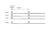
- the eNB 200 performs intermittent transmission (DTX: Discontinuous Transmission) for intermittently transmitting a radio signal by activating the transmission unit 211 intermittently. Also, the eNB 200 broadcasts the activation pattern of the transmission unit 211 (hereinafter referred to as “DTX pattern”) to the UEs 100-1 to 100-n by broadcast.
- DTX pattern the activation pattern of the transmission unit 211
- each of the UEs 100-1 to 100-n is in a state (idle state) in which communication with the eNB 200 is not performed.
- each of the UEs 100-1 to 100-n recognizes a DTX pattern based on broadcast information from the eNB 200.
- the eNB 200 activates the transmission unit 211 at a constant activation cycle (dtx cycle), and recognizes that the transmission unit 211 is in an operating state for a certain activation time (on Duration) for each dtx cycle.
- the eNB 200 that performs intermittent transmission (DTX) temporarily changes the DTX pattern in response to reception of a communication request from the UE 100-2.
- the eNB 200 shortens the activation cycle (dtx Cycle) and extends the activation time (on Duration).
- the eNB 200 notifies UE100-2 of the pattern information which shows the DTX pattern after a change.
- the eNB 200 includes the pattern information in the RRC message and notifies the UE 100-2. Note that the eNB 200 does not notify the UE 100 other than the UE 100-2 of the pattern information.
- the UE 100-2 recognizes the changed DTX pattern based on the pattern information, and performs reception from the eNB 200 according to the changed DTX pattern.
- the UE 100-2 can perform desired communication, it is possible to suppress degradation of service quality while performing power saving of the eNB 200.
- the changed DTX pattern is based on information related to communication performed by the UE 100.
- “information related to communication” is information indicating QoS (Quality of Service) required for the communication or information indicating the data amount of the communication.
- the eNB 200 sets the DTX pattern based on the QCI (QoS Class Identifier) indicating the QoS of the bearer established after the generation of the communication request.
- FIG. 10 is a diagram illustrating a configuration example of a table for setting the DTX pattern based on the QCI.
- the eNB 200 holds this table in advance.
- an appropriate DTX pattern (here, a start cycle) is associated with each QCI.
- FTP data download
- Web access, etc. a necessary bandwidth is instantly allocated.
- the activation period is changed at an appropriate interval.
- the eNB 200 sets the DTX pattern based on the data amount accumulated in the buffer of the eNB 200 after the communication request from the UE 100 is generated. Specifically, the eNB 200 shortens the activation cycle (dtx cycle) and lengthens the activation time (on Duration) as the amount of data stored in the buffer increases.
- the eNB 200 notifies the UE 100 that is the transmission source of the communication request of the pattern information indicating the changed DTX pattern.
- the pattern information includes information indicating an activation cycle (dtx cycle), information indicating an activation time (on Duration) when the transmission unit 211 is activated, an offset value (dtx StartOffset) that determines a timing at which the transmission unit 211 is activated, and , At least one of.
- the pattern information (DTX setting information) included in the RRC message can be in the following format, for example.
- UE100 which received pattern information (DTX setting information) calculates a starting timing according to the following formulas.
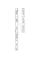
- FIG. 11 is an operation sequence diagram according to the present embodiment.
- the eNB 200 performs intermittent transmission (DTX) with a DTX pattern common to all UEs 100.
- DTX intermittent transmission
- FIG. 11 an example of changing the DTX pattern based on QoS will be described.
- step S11 the UE 100 transmits an SR (Scheduling Request) requesting radio resource allocation to the eNB 200.
- SR corresponds to a communication request.
- step S12 the eNB 200 starts a timer (T100) for the UE 100.
- This timer (T100) is a timer set to prevent the transmission from being suspended during the subsequent processing for SR reception. Specifically, it is assumed that up to S20 ends during the timer (T100).
- step S ⁇ b> 13 the eNB 200 transmits UL Grant indicating the uplink allocated radio resource to the UE 100.
- step S14 the UE 100 transmits a BSR (Buffer Status Report) indicating the buffer storage amount of the UE 100 to the eNB 200 using the uplink allocated radio resource.
- BSR Buffer Status Report
- step S15 the eNB 200 transmits UL Grant indicating the uplink assigned radio resource to the UE 100 based on the buffer accumulation amount indicated by the BSR.
- step S16 the UE 100 transmits uplink data to the eNB 200 using the uplink allocated radio resource.
- step S17 the eNB 200 transfers the data from the UE 100 to the core network (MME / S-GW 300).
- step S18 the core network (MME / S-GW 300) transmits the QCI indicating the QoS set in the bearer of the UE 100 to the eNB 200.
- step S19 the eNB 200 sets a DTX pattern corresponding to the QCI with reference to the table shown in FIG. As a result, the DTX pattern is changed.
- step S20 the eNB 200 transmits pattern information (DTX setting information) indicating the changed DTX pattern to the UE 100.
- the UE 100-2 recognizes the changed DTX pattern based on the pattern information.
- step S21 the core network (MME / S-GW 300) transmits data for the UE 100 to the eNB 200.
- step S22 the eNB 200 transfers data from the core network (MME / S-GW 300) to the UE 100.
- the eNB 200 performs transmission to the UE 100 within the startup time (on Duration) based on the DTX pattern.
- the UE 100 recognizes the changed DTX pattern and performs reception from the eNB 200 in accordance with the changed DTX pattern.
- the eNB 200 accumulates data from the core network (MME / S-GW 300) (step S23).
- the data is transmitted to the UE 100 (step S24).
- the temporary DTX pattern for the UE 100 is terminated (step S25), and an end notification indicating the end of the DTX pattern is sent to the UE 100. (Step S26).
- the end notification may include information indicating the original DTX pattern (common DTX pattern).
- FIG. 12 is a diagram illustrating an example of a message configuration when a random access response (RAR) is used.
- RAR is a response message to the random access preamble that UE 100 transmits at the time of initial connection.
- the RAR according to the present modification includes DTX pattern information (Temporary DTX config.).
- the DTX pattern information (Temporary DTX config.) Includes information indicating a start cycle (dtx cycle), information indicating a start time (on Duration), and an offset value (dtx StartOffset).
- dtx cycle start cycle
- On Duration start time
- dtx StartOffset offset value
- all these parameters are not necessarily required. For example, only the activation time (on Duration) may be set, and the period from the RAR transmission timing to the activation time (on Duration) may be valid (eNB 200 is transmitted).
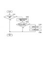
- the eNB 200 may cancel the intermittent transmission (DTX) and start normal transmission based on the reception status of the communication requests from the plurality of UEs 100 in the cell. This is because, if a certain amount of communication is required, it is desirable to cancel intermittent transmission (DTX) in order to improve service quality.
- FIG. 13 is an operation flowchart of the eNB 200 according to this modification.
- the eNB 200 performs intermittent transmission (DTX) (step S101; Yes)
- the eNB 200 counts the activation time (on Duration) in a certain period (step S102). If the total activation time is equal to or greater than the threshold (step S103; Yes), the intermittent transmission (DTX) is canceled and the normal state is entered (step S104), and the intermittent transmission (DTX) is canceled in the own cell.
- Each UE 100 is notified (step S105).
- the eNB 200 may not only notify the UE 100 of the DTX pattern but also notify the neighboring eNB 200. Thereby, the adjacent eNB 200 can appropriately perform mobility control of the UE 100 under the control.
- the present invention is not limited to the LTE system, and the present invention may be applied to a system other than the LTE system.
- the base station, the user terminal, and the communication control method according to the present invention are useful in the mobile communication field because power saving can be realized while suppressing a decrease in service quality.
Landscapes
- Engineering & Computer Science (AREA)
- Computer Networks & Wireless Communication (AREA)
- Signal Processing (AREA)
- Quality & Reliability (AREA)
- Mobile Radio Communication Systems (AREA)
Priority Applications (2)
| Application Number | Priority Date | Filing Date | Title |
|---|---|---|---|
| US14/781,528 US20160044739A1 (en) | 2013-04-05 | 2014-04-03 | Base station, user terminal, and communication control method |
| EP14778666.9A EP2983417A4 (en) | 2013-04-05 | 2014-04-03 | BASIC STATION, USER DEVICE, AND COMMUNICATION CONTROL PROCEDURE |
Applications Claiming Priority (2)
| Application Number | Priority Date | Filing Date | Title |
|---|---|---|---|
| JP2013080001A JP2014204345A (ja) | 2013-04-05 | 2013-04-05 | 基地局、ユーザ端末、及び通信制御方法 |
| JP2013-080001 | 2013-04-05 |
Publications (1)
| Publication Number | Publication Date |
|---|---|
| WO2014163139A1 true WO2014163139A1 (ja) | 2014-10-09 |
Family
ID=51658430
Family Applications (1)
| Application Number | Title | Priority Date | Filing Date |
|---|---|---|---|
| PCT/JP2014/059831 Ceased WO2014163139A1 (ja) | 2013-04-05 | 2014-04-03 | 基地局、ユーザ端末、及び通信制御方法 |
Country Status (4)
| Country | Link |
|---|---|
| US (1) | US20160044739A1 (enExample) |
| EP (1) | EP2983417A4 (enExample) |
| JP (1) | JP2014204345A (enExample) |
| WO (1) | WO2014163139A1 (enExample) |
Families Citing this family (7)
| Publication number | Priority date | Publication date | Assignee | Title |
|---|---|---|---|---|
| US12022464B2 (en) * | 2018-07-16 | 2024-06-25 | Huawei Technologies Co., Ltd. | Apparatus and methods of scheduling for low power consumption |
| CN116939779A (zh) * | 2022-03-30 | 2023-10-24 | 大唐移动通信设备有限公司 | Dtx传输方法、网络节点、网络设备和存储介质 |
| CN118509959A (zh) * | 2023-02-14 | 2024-08-16 | 大唐移动通信设备有限公司 | 通信方法、设备及装置 |
| JP2026068037A (ja) * | 2023-03-02 | 2026-04-22 | 株式会社Nttドコモ | 端末及び通信方法 |
| EP4444029A1 (en) * | 2023-04-06 | 2024-10-09 | Nokia Technologies Oy | Communication of information relating to cell dtx/drx patterns |
| WO2025030539A1 (en) * | 2023-08-10 | 2025-02-13 | Nokia Shanghai Bell Co., Ltd. | Csi-rs transmission |
| WO2025150505A1 (ja) * | 2024-01-11 | 2025-07-17 | 日本電気株式会社 | 制御装置、無線アクセスネットワークノード、無線端末、及びこれらの方法 |
Citations (6)
| Publication number | Priority date | Publication date | Assignee | Title |
|---|---|---|---|---|
| JP2010508704A (ja) * | 2006-10-27 | 2010-03-18 | インターデイジタル テクノロジー コーポレーション | 無線システムにおける不連続な受信を強化する方法及び装置 |
| JP2010521076A (ja) * | 2007-03-09 | 2010-06-17 | 日本電気株式会社 | 移動体通信システム用の不連続受信/送信 |
| JP2010521826A (ja) * | 2007-03-12 | 2010-06-24 | シャープ株式会社 | 間欠受信のための明示的なレイヤ2シグナリング |
| WO2011096860A1 (en) * | 2010-02-04 | 2011-08-11 | Telefonaktiebolaget L M Ericsson (Publ) | Prioritization of energy over system throughput in a wireless communications system |
| JP2011250255A (ja) * | 2010-05-28 | 2011-12-08 | Ntt Docomo Inc | 無線通信システム及び間欠送信方法 |
| JP2013080001A (ja) | 2011-09-30 | 2013-05-02 | Fujifilm Corp | レンズ装置及び撮像装置 |
Family Cites Families (14)
| Publication number | Priority date | Publication date | Assignee | Title |
|---|---|---|---|---|
| US7110785B1 (en) * | 1999-12-03 | 2006-09-19 | Nortel Networks Limited | Performing power control in a mobile communications system |
| US6975868B2 (en) * | 2001-02-21 | 2005-12-13 | Qualcomm Incorporated | Method and apparatus for IS-95B reverse link supplemental code channel frame validation and fundamental code channel rate decision improvement |
| GB2382746B (en) * | 2001-11-20 | 2005-12-14 | Ericsson Telefon Ab L M | Establishing radio communication channels |
| WO2007144956A1 (ja) * | 2006-06-16 | 2007-12-21 | Mitsubishi Electric Corporation | 移動体通信システム及び移動端末 |
| FI20060666A0 (fi) * | 2006-07-07 | 2006-07-07 | Nokia Corp | Menetelmä ja järjestelmä epäjatkuvan lähetyksen toiminnallisuuden parantamiseksi |
| BRPI0714637A2 (pt) * | 2006-08-21 | 2013-05-07 | Interdigital Tech Corp | mÉtodo e aparelho de alocaÇço dinÂmica de processos harq no link superior |
| WO2008069950A2 (en) * | 2006-12-01 | 2008-06-12 | Interdigital Technology Corporation | Method and apparatus for controlling discontinuous transmission and reception |
| KR20080066561A (ko) * | 2007-01-12 | 2008-07-16 | 한국전자통신연구원 | 패킷 기반 통신 시스템에서 측정 정보 보고 방법 |
| US8184599B2 (en) * | 2008-06-23 | 2012-05-22 | Qualcomm Incorporated | Management of UE operation in a multi-carrier communication system |
| TWI475856B (zh) * | 2008-11-25 | 2015-03-01 | Interdigital Patent Holdings | 多數上鏈載波及多數下鏈載波利用方法及裝置 |
| CN102804885B (zh) * | 2009-06-17 | 2015-12-16 | 富士通株式会社 | 通信装置、通信系统以及通信方法 |
| US8462736B2 (en) * | 2009-06-19 | 2013-06-11 | Telefonaktiebolaget L M Ericsson (Publ) | Telecommunications method and apparatus for facilitating positioning measurements |
| US8737994B2 (en) * | 2010-11-05 | 2014-05-27 | Qualcomm Incorporated | Discontinuous transmission in femtocells |
| US9026140B2 (en) * | 2012-10-12 | 2015-05-05 | Telefonaktiebolaget L M Ericsson (Publ) | Second node, positioning node and methods therein |
-
2013
- 2013-04-05 JP JP2013080001A patent/JP2014204345A/ja active Pending
-
2014
- 2014-04-03 WO PCT/JP2014/059831 patent/WO2014163139A1/ja not_active Ceased
- 2014-04-03 US US14/781,528 patent/US20160044739A1/en not_active Abandoned
- 2014-04-03 EP EP14778666.9A patent/EP2983417A4/en not_active Withdrawn
Patent Citations (6)
| Publication number | Priority date | Publication date | Assignee | Title |
|---|---|---|---|---|
| JP2010508704A (ja) * | 2006-10-27 | 2010-03-18 | インターデイジタル テクノロジー コーポレーション | 無線システムにおける不連続な受信を強化する方法及び装置 |
| JP2010521076A (ja) * | 2007-03-09 | 2010-06-17 | 日本電気株式会社 | 移動体通信システム用の不連続受信/送信 |
| JP2010521826A (ja) * | 2007-03-12 | 2010-06-24 | シャープ株式会社 | 間欠受信のための明示的なレイヤ2シグナリング |
| WO2011096860A1 (en) * | 2010-02-04 | 2011-08-11 | Telefonaktiebolaget L M Ericsson (Publ) | Prioritization of energy over system throughput in a wireless communications system |
| JP2011250255A (ja) * | 2010-05-28 | 2011-12-08 | Ntt Docomo Inc | 無線通信システム及び間欠送信方法 |
| JP2013080001A (ja) | 2011-09-30 | 2013-05-02 | Fujifilm Corp | レンズ装置及び撮像装置 |
Non-Patent Citations (1)
| Title |
|---|
| See also references of EP2983417A4 |
Also Published As
| Publication number | Publication date |
|---|---|
| US20160044739A1 (en) | 2016-02-11 |
| EP2983417A4 (en) | 2016-11-02 |
| JP2014204345A (ja) | 2014-10-27 |
| EP2983417A1 (en) | 2016-02-10 |
Similar Documents
| Publication | Publication Date | Title |
|---|---|---|
| JP6082153B2 (ja) | ユーザ端末、基地局、プロセッサ及び通信制御方法 | |
| JP6494117B2 (ja) | 端末装置、基地局装置、通信システム、通知方法および集積回路 | |
| JP6239280B2 (ja) | ユーザ端末、プロセッサ及び移動通信システム | |
| JP5926394B2 (ja) | 移動通信システム、ユーザ端末、基地局及びプロセッサ | |
| WO2014017476A1 (ja) | 移動通信システム、基地局、ユーザ端末、及びプロセッサ | |
| US10021039B2 (en) | Mobile communication system and user terminal | |
| WO2014163139A1 (ja) | 基地局、ユーザ端末、及び通信制御方法 | |
| WO2014163138A1 (ja) | 基地局 | |
| JP6785215B2 (ja) | 無線端末 | |
| WO2014069221A1 (ja) | 移動通信システム、ユーザ端末、基地局、プロセッサ及び通信制御方法 | |
| JP5894107B2 (ja) | 基地局、ユーザ端末及びプロセッサ | |
| JP6200078B2 (ja) | ユーザ端末、プロセッサ及び方法 | |
| JP6140014B2 (ja) | ユーザ端末、基地局、及びプロセッサ | |
| JP6140323B2 (ja) | 移動通信システム、基地局及び方法 | |
| JP6298442B2 (ja) | 基地局及びプロセッサ | |
| WO2014192629A1 (ja) | ユーザ端末、基地局及びプロセッサ | |
| JP6034956B2 (ja) | 移動通信システム、基地局及びユーザ端末 | |
| WO2015141823A1 (ja) | 端末装置、基地局装置、通信システム、通知方法および集積回路 |
Legal Events
| Date | Code | Title | Description |
|---|---|---|---|
| 121 | Ep: the epo has been informed by wipo that ep was designated in this application |
Ref document number: 14778666 Country of ref document: EP Kind code of ref document: A1 |
|
| REEP | Request for entry into the european phase |
Ref document number: 2014778666 Country of ref document: EP |
|
| WWE | Wipo information: entry into national phase |
Ref document number: 2014778666 Country of ref document: EP |
|
| WWE | Wipo information: entry into national phase |
Ref document number: 14781528 Country of ref document: US |
|
| NENP | Non-entry into the national phase |
Ref country code: DE |