WO2014162989A1 - 充電制御装置、充電制御方法及び充電制御システム - Google Patents
充電制御装置、充電制御方法及び充電制御システム Download PDFInfo
- Publication number
- WO2014162989A1 WO2014162989A1 PCT/JP2014/059015 JP2014059015W WO2014162989A1 WO 2014162989 A1 WO2014162989 A1 WO 2014162989A1 JP 2014059015 W JP2014059015 W JP 2014059015W WO 2014162989 A1 WO2014162989 A1 WO 2014162989A1
- Authority
- WO
- WIPO (PCT)
- Prior art keywords
- charging
- current
- amount
- secondary battery
- point
- Prior art date
- Legal status (The legal status is an assumption and is not a legal conclusion. Google has not performed a legal analysis and makes no representation as to the accuracy of the status listed.)
- Ceased
Links
Images


Classifications
-
- B—PERFORMING OPERATIONS; TRANSPORTING
- B60—VEHICLES IN GENERAL
- B60L—PROPULSION OF ELECTRICALLY-PROPELLED VEHICLES; SUPPLYING ELECTRIC POWER FOR AUXILIARY EQUIPMENT OF ELECTRICALLY-PROPELLED VEHICLES; ELECTRODYNAMIC BRAKE SYSTEMS FOR VEHICLES IN GENERAL; MAGNETIC SUSPENSION OR LEVITATION FOR VEHICLES; MONITORING OPERATING VARIABLES OF ELECTRICALLY-PROPELLED VEHICLES; ELECTRIC SAFETY DEVICES FOR ELECTRICALLY-PROPELLED VEHICLES
- B60L3/00—Electric devices on electrically-propelled vehicles for safety purposes; Monitoring operating variables, e.g. speed, deceleration or energy consumption
- B60L3/0023—Detecting, eliminating, remedying or compensating for drive train abnormalities, e.g. failures within the drive train
- B60L3/0046—Detecting, eliminating, remedying or compensating for drive train abnormalities, e.g. failures within the drive train relating to electric energy storage systems, e.g. batteries or capacitors
-
- B—PERFORMING OPERATIONS; TRANSPORTING
- B60—VEHICLES IN GENERAL
- B60L—PROPULSION OF ELECTRICALLY-PROPELLED VEHICLES; SUPPLYING ELECTRIC POWER FOR AUXILIARY EQUIPMENT OF ELECTRICALLY-PROPELLED VEHICLES; ELECTRODYNAMIC BRAKE SYSTEMS FOR VEHICLES IN GENERAL; MAGNETIC SUSPENSION OR LEVITATION FOR VEHICLES; MONITORING OPERATING VARIABLES OF ELECTRICALLY-PROPELLED VEHICLES; ELECTRIC SAFETY DEVICES FOR ELECTRICALLY-PROPELLED VEHICLES
- B60L58/00—Methods or circuit arrangements for monitoring or controlling batteries or fuel cells, specially adapted for electric vehicles
- B60L58/10—Methods or circuit arrangements for monitoring or controlling batteries or fuel cells, specially adapted for electric vehicles for monitoring or controlling batteries
- B60L58/12—Methods or circuit arrangements for monitoring or controlling batteries or fuel cells, specially adapted for electric vehicles for monitoring or controlling batteries responding to state of charge [SoC]
- B60L58/13—Maintaining the SoC within a determined range
-
- B—PERFORMING OPERATIONS; TRANSPORTING
- B60—VEHICLES IN GENERAL
- B60L—PROPULSION OF ELECTRICALLY-PROPELLED VEHICLES; SUPPLYING ELECTRIC POWER FOR AUXILIARY EQUIPMENT OF ELECTRICALLY-PROPELLED VEHICLES; ELECTRODYNAMIC BRAKE SYSTEMS FOR VEHICLES IN GENERAL; MAGNETIC SUSPENSION OR LEVITATION FOR VEHICLES; MONITORING OPERATING VARIABLES OF ELECTRICALLY-PROPELLED VEHICLES; ELECTRIC SAFETY DEVICES FOR ELECTRICALLY-PROPELLED VEHICLES
- B60L2240/00—Control parameters of input or output; Target parameters
- B60L2240/40—Drive Train control parameters
- B60L2240/54—Drive Train control parameters related to batteries
- B60L2240/545—Temperature
-
- B—PERFORMING OPERATIONS; TRANSPORTING
- B60—VEHICLES IN GENERAL
- B60L—PROPULSION OF ELECTRICALLY-PROPELLED VEHICLES; SUPPLYING ELECTRIC POWER FOR AUXILIARY EQUIPMENT OF ELECTRICALLY-PROPELLED VEHICLES; ELECTRODYNAMIC BRAKE SYSTEMS FOR VEHICLES IN GENERAL; MAGNETIC SUSPENSION OR LEVITATION FOR VEHICLES; MONITORING OPERATING VARIABLES OF ELECTRICALLY-PROPELLED VEHICLES; ELECTRIC SAFETY DEVICES FOR ELECTRICALLY-PROPELLED VEHICLES
- B60L2240/00—Control parameters of input or output; Target parameters
- B60L2240/40—Drive Train control parameters
- B60L2240/54—Drive Train control parameters related to batteries
- B60L2240/547—Voltage
-
- B—PERFORMING OPERATIONS; TRANSPORTING
- B60—VEHICLES IN GENERAL
- B60L—PROPULSION OF ELECTRICALLY-PROPELLED VEHICLES; SUPPLYING ELECTRIC POWER FOR AUXILIARY EQUIPMENT OF ELECTRICALLY-PROPELLED VEHICLES; ELECTRODYNAMIC BRAKE SYSTEMS FOR VEHICLES IN GENERAL; MAGNETIC SUSPENSION OR LEVITATION FOR VEHICLES; MONITORING OPERATING VARIABLES OF ELECTRICALLY-PROPELLED VEHICLES; ELECTRIC SAFETY DEVICES FOR ELECTRICALLY-PROPELLED VEHICLES
- B60L2240/00—Control parameters of input or output; Target parameters
- B60L2240/40—Drive Train control parameters
- B60L2240/54—Drive Train control parameters related to batteries
- B60L2240/549—Current
-
- B—PERFORMING OPERATIONS; TRANSPORTING
- B60—VEHICLES IN GENERAL
- B60L—PROPULSION OF ELECTRICALLY-PROPELLED VEHICLES; SUPPLYING ELECTRIC POWER FOR AUXILIARY EQUIPMENT OF ELECTRICALLY-PROPELLED VEHICLES; ELECTRODYNAMIC BRAKE SYSTEMS FOR VEHICLES IN GENERAL; MAGNETIC SUSPENSION OR LEVITATION FOR VEHICLES; MONITORING OPERATING VARIABLES OF ELECTRICALLY-PROPELLED VEHICLES; ELECTRIC SAFETY DEVICES FOR ELECTRICALLY-PROPELLED VEHICLES
- B60L2240/00—Control parameters of input or output; Target parameters
- B60L2240/80—Time limits
-
- B—PERFORMING OPERATIONS; TRANSPORTING
- B60—VEHICLES IN GENERAL
- B60L—PROPULSION OF ELECTRICALLY-PROPELLED VEHICLES; SUPPLYING ELECTRIC POWER FOR AUXILIARY EQUIPMENT OF ELECTRICALLY-PROPELLED VEHICLES; ELECTRODYNAMIC BRAKE SYSTEMS FOR VEHICLES IN GENERAL; MAGNETIC SUSPENSION OR LEVITATION FOR VEHICLES; MONITORING OPERATING VARIABLES OF ELECTRICALLY-PROPELLED VEHICLES; ELECTRIC SAFETY DEVICES FOR ELECTRICALLY-PROPELLED VEHICLES
- B60L2260/00—Operating Modes
- B60L2260/40—Control modes
- B60L2260/50—Control modes by future state prediction
- B60L2260/52—Control modes by future state prediction drive range estimation, e.g. of estimation of available travel distance
-
- B—PERFORMING OPERATIONS; TRANSPORTING
- B60—VEHICLES IN GENERAL
- B60L—PROPULSION OF ELECTRICALLY-PROPELLED VEHICLES; SUPPLYING ELECTRIC POWER FOR AUXILIARY EQUIPMENT OF ELECTRICALLY-PROPELLED VEHICLES; ELECTRODYNAMIC BRAKE SYSTEMS FOR VEHICLES IN GENERAL; MAGNETIC SUSPENSION OR LEVITATION FOR VEHICLES; MONITORING OPERATING VARIABLES OF ELECTRICALLY-PROPELLED VEHICLES; ELECTRIC SAFETY DEVICES FOR ELECTRICALLY-PROPELLED VEHICLES
- B60L2260/00—Operating Modes
- B60L2260/40—Control modes
- B60L2260/50—Control modes by future state prediction
- B60L2260/54—Energy consumption estimation
-
- B—PERFORMING OPERATIONS; TRANSPORTING
- B60—VEHICLES IN GENERAL
- B60L—PROPULSION OF ELECTRICALLY-PROPELLED VEHICLES; SUPPLYING ELECTRIC POWER FOR AUXILIARY EQUIPMENT OF ELECTRICALLY-PROPELLED VEHICLES; ELECTRODYNAMIC BRAKE SYSTEMS FOR VEHICLES IN GENERAL; MAGNETIC SUSPENSION OR LEVITATION FOR VEHICLES; MONITORING OPERATING VARIABLES OF ELECTRICALLY-PROPELLED VEHICLES; ELECTRIC SAFETY DEVICES FOR ELECTRICALLY-PROPELLED VEHICLES
- B60L2260/00—Operating Modes
- B60L2260/40—Control modes
- B60L2260/50—Control modes by future state prediction
- B60L2260/58—Departure time prediction
-
- Y—GENERAL TAGGING OF NEW TECHNOLOGICAL DEVELOPMENTS; GENERAL TAGGING OF CROSS-SECTIONAL TECHNOLOGIES SPANNING OVER SEVERAL SECTIONS OF THE IPC; TECHNICAL SUBJECTS COVERED BY FORMER USPC CROSS-REFERENCE ART COLLECTIONS [XRACs] AND DIGESTS
- Y02—TECHNOLOGIES OR APPLICATIONS FOR MITIGATION OR ADAPTATION AGAINST CLIMATE CHANGE
- Y02T—CLIMATE CHANGE MITIGATION TECHNOLOGIES RELATED TO TRANSPORTATION
- Y02T10/00—Road transport of goods or passengers
- Y02T10/60—Other road transportation technologies with climate change mitigation effect
- Y02T10/70—Energy storage systems for electromobility, e.g. batteries
-
- Y—GENERAL TAGGING OF NEW TECHNOLOGICAL DEVELOPMENTS; GENERAL TAGGING OF CROSS-SECTIONAL TECHNOLOGIES SPANNING OVER SEVERAL SECTIONS OF THE IPC; TECHNICAL SUBJECTS COVERED BY FORMER USPC CROSS-REFERENCE ART COLLECTIONS [XRACs] AND DIGESTS
- Y02—TECHNOLOGIES OR APPLICATIONS FOR MITIGATION OR ADAPTATION AGAINST CLIMATE CHANGE
- Y02T—CLIMATE CHANGE MITIGATION TECHNOLOGIES RELATED TO TRANSPORTATION
- Y02T10/00—Road transport of goods or passengers
- Y02T10/60—Other road transportation technologies with climate change mitigation effect
- Y02T10/7072—Electromobility specific charging systems or methods for batteries, ultracapacitors, supercapacitors or double-layer capacitors
-
- Y—GENERAL TAGGING OF NEW TECHNOLOGICAL DEVELOPMENTS; GENERAL TAGGING OF CROSS-SECTIONAL TECHNOLOGIES SPANNING OVER SEVERAL SECTIONS OF THE IPC; TECHNICAL SUBJECTS COVERED BY FORMER USPC CROSS-REFERENCE ART COLLECTIONS [XRACs] AND DIGESTS
- Y02—TECHNOLOGIES OR APPLICATIONS FOR MITIGATION OR ADAPTATION AGAINST CLIMATE CHANGE
- Y02T—CLIMATE CHANGE MITIGATION TECHNOLOGIES RELATED TO TRANSPORTATION
- Y02T90/00—Enabling technologies or technologies with a potential or indirect contribution to GHG emissions mitigation
- Y02T90/10—Technologies relating to charging of electric vehicles
- Y02T90/14—Plug-in electric vehicles
Definitions
- the present invention relates to a charge control device, a charge control method, and a charge control system that control charging of a secondary battery provided in a vehicle traveling on a route having a plurality of charging points.
- deterioration of the secondary battery is a problem. Specifically, the secondary battery needs to be replaced with a new secondary battery due to deterioration.
- the introduction of the secondary battery has a problem that it takes a cost for replacement. It is known that the progress of the deterioration of the secondary battery is affected by the use range of the charging rate of the secondary battery and the temperature of the secondary battery.
- Patent Document 1 charging is performed so that the increase / decrease in the charging rate of the secondary battery in the path is within a predetermined range including the optimal charging rate, thereby degrading the usage rate of the charging rate of the secondary battery.
- a technique for suppressing the progression of the above is disclosed.
- Patent Document 1 does not disclose a technique for suppressing the progress of deterioration based on the temperature of the secondary battery.
- the objective of this invention is providing the charge control apparatus, the charge control method, and the charge control system which solve the subject mentioned above.
- the charge control device includes a current value specifying unit and a charge control unit.
- the current value specifying unit sets a current value obtained by dividing the amount of current that the vehicle should charge the secondary battery at the charging point by an allowable charging time at the charging point to a charged state of the secondary battery. It specifies based on the charge amount which is the physical quantity which concerns.
- the charging control unit when the vehicle reaches the charging point, the charging device provided at the charging point, the current of the current value specified by the current value specifying unit, during the allowable charging time, The secondary battery of the vehicle is charged.
- One aspect includes a current value storage unit in the above-described charge control device.
- the current value storage unit is configured to obtain a current value obtained by dividing the amount of current to be charged in the secondary battery at each charging point by an allowable charging time at the charging point, when the secondary battery reaches the charging point. This is stored for each battery charge.
- the current value specifying unit specifies a current value stored in the current value storage unit in association with a current charge amount of the secondary battery as a current value that the vehicle should charge the secondary battery at the charging point. To do.
- the current value at a certain charging point specified by the current value specifying unit is set so that the amount of charge of the secondary battery when the vehicle reaches the end point of the route is set to a predetermined target value. It is a current value obtained by dividing the optimum amount of current for charging the secondary battery at the charging point by the allowable charging time.
- the current value specifying unit specifies a current value of a current to be charged in the secondary battery based on a current state of the vehicle or the secondary battery.
- One aspect is a charging control method for controlling charging of a secondary battery provided in a vehicle traveling on a route having a plurality of charging points.
- a physical value related to a charging state of the secondary battery is obtained by dividing a current value that the vehicle should charge the secondary battery at the charging point by an allowable charging time at the charging point. And a step of specifying based on the charged amount.
- the charging control method is configured to supply a current having the specified current value to a charging device provided at the charging point during the allowable charging time. Charging the battery.
- the current value specified in the step of specifying the current value is determined at the charging point in order to set the amount of charge of the secondary battery when the vehicle reaches the end point of the route to a predetermined target value. This is a current value obtained by dividing the optimum amount of current for charging the secondary battery by the allowable charging time.
- the charge control system includes a current amount specifying unit, a current value specifying unit, and a charge control unit.
- the current amount specifying unit determines a charge amount of the secondary battery when the vehicle reaches an end point of the route for each charge amount that is a physical amount related to a charge state of the charge point and the secondary battery. In order to obtain the target value, an optimum amount of current for charging the secondary battery at the charging point is specified.
- the current value specifying unit divides the current amount specified by the current amount specifying unit by an allowable charging time at the charging point based on a charge amount of the secondary battery when the vehicle reaches the charging point.
- the obtained current value is specified.
- the charging control unit is configured to supply a current of the current value specified by the current value specifying unit for the charging point and the charge amount to a charging device provided at the charging point.
- the secondary battery of the vehicle is charged during the allowable charging time.
- the current amount calculation unit includes the charging point, a starting point charging amount that is a charging amount of the secondary battery at the charging point, and an end point charging amount that is a charging amount of the secondary battery at a charging point next to the charging point.
- the amount of current is calculated for each combination.
- the current amount is set so that the charge amount of the secondary battery when the vehicle reaches the next charge point is set to the end point charge amount when the charge amount of the secondary battery is the start point charge amount.
- the current amount specifying unit relates to the charging point and the current amount for each current amount calculated by the current amount calculating unit in order from the end point side of the path with respect to the charging point for which the optimum current amount is not specified.
- the evaluation value includes an evaluation value that monotonously increases with the current amount, and the secondary battery when the vehicle reaches the charging point next to the charging point when the secondary battery is charged with the current amount. It is a value obtained by adding the evaluation value for the charge amount.
- the current amount specifying unit specifies the current amount having the smallest evaluation value as the optimum current amount.
- the temperature of the secondary battery monotonically increases with respect to the effective current value of the secondary battery, and the effective current value is determined depending on the sum of squares of the energized current.
- the charge control unit supplies a current obtained by dividing the current amount specified by the current amount specifying unit by the allowable charging time to the secondary battery. Therefore, the charge control unit can charge the secondary battery with a minimum current. The charge control unit can suppress the progress of deterioration based on the temperature of the secondary battery.
- FIG. 1 is a schematic diagram showing an embodiment of a charge control system 100 according to the first embodiment of the present invention.
- the charging control system 100 is a system that controls charging of the secondary battery 210.
- the secondary battery 210 is provided in the vehicle 200 that travels on the route.
- N charging points including charging devices 10-1 to 10-N (hereinafter, charging devices 10-1 to 10-N are collectively referred to as charging device 10) are provided.
- one of the charging points is provided at the end point of the route.
- the charge control system 100 includes a current value calculation device 110 and a charge control device 120.
- the current value calculation device 110 calculates an appropriate current value for charging the secondary battery 210 for each charging point.
- the charging control device 120 controls charging of the secondary battery 210 based on the current value calculated by the current value calculating device 110.
- Charging control device 120 is mounted on vehicle 200.
- FIG. 2 is a schematic block diagram showing the configuration of the charging control system 100 according to the first embodiment of the present invention.
- the current value calculation device 110 includes a current amount calculation unit 111, a current amount identification unit 112, an evaluation value storage unit 113, a current value calculation unit 114, a current value storage unit 115, and an output unit 116.
- the current amount calculation unit 111 includes a charging point, an SOC (State Of Charge) (hereinafter referred to as a starting point SOC) of the secondary battery 210 at the charging point, and a secondary battery at the charging point next to the charging point.
- SOC State Of Charge
- SOC State Of Charge
- end point SOC For each combination with 210 SOC (hereinafter referred to as end point SOC), the amount of current that needs to be charged to satisfy the end point SOC is calculated.
- the above calculation is performed for each stage. In this stage, the SOC of the secondary battery 210 is divided into a plurality of stages within the operating range.
- the current amount specifying unit 112 calculates an evaluation value indicating the appropriateness of charging the secondary battery 210 with the current amount.
- the current amount specifying unit 112 specifies an optimum amount of current to be charged in the secondary battery 210 based on the evaluation value.
- the evaluation value indicates that the smaller the value is, the more appropriate it is.
- the current amount specifying unit 112 records the smallest value among the evaluation values calculated for a certain charging point and a certain starting point SOC in the evaluation value storage unit 113 in association with the charging point and the starting point SOC.
- Evaluation value storage unit 113 stores the evaluation value in association with the combination of the charging point and the starting point SOC.
- the current value calculating unit 114 For each combination of the charging point and the starting point SOC, the current value calculating unit 114 records the current value in the current value storage unit 115 in association with the charging point and the starting point SOC.
- the current value is a current value obtained by dividing the current amount specified by the current amount specifying unit 112 by the allowable charging time at the charging point.
- the current value storage unit 115 stores a current value appropriate for charging the secondary battery 210 in association with the combination of the charging point and the starting point SOC.
- the output unit 116 outputs the current value stored in the current value storage unit 115 to the charging control device 120.
- the charging control device 120 includes an input unit 121, a current value storage unit 122, an SOC specifying unit 123, a current value specifying unit 124, and a charging control unit 125.
- Input unit 121 receives an input of a current value for each combination of a charging point and a starting point SOC from current value calculation device 110.
- the input unit 121 records the current value in the current value storage unit 122 in association with the charging point and the starting point SOC.
- the current value storage unit 122 stores a current value appropriate for charging the secondary battery 210 in association with the combination of the charging point and the starting point SOC.
- the SOC specifying unit 123 specifies the SOC of the secondary battery 210.
- the current value specifying unit 124 reads out a current value associated with the charging point and the SOC of the secondary battery 210 from the current value storage unit 122.
- the charging control unit 125 sends the current of the current value read by the current value specifying unit 124 to the charging device 10 provided at the charging point, and the allowable charging time at the charging point. During this period, the secondary battery 210 is charged.
- the current value calculation device 110 calculates a current value for optimal charging for each charging point and each SOC of the secondary battery 210 in advance. Then, the charging control device 120 according to the present embodiment identifies an optimal current value from among the current values calculated in advance based on the SOC of the secondary battery 210 when the charging point is reached, and based on the current value. Then, the secondary battery 210 is charged.
- FIG. 3 is a flowchart showing the operation of the current value calculation device 110 according to the first embodiment of the present invention.
- the current value calculation device 110 selects the SOC stage of the secondary battery 210 one by one.
- the current value calculation device 110 performs the processing shown in the following steps S2 to S7 for the selected stage (step S1).
- step S1 the SOC stage selected in step S1 is referred to as the j-th stage.
- the current amount calculation unit 111 calculates a current amount (step S2).
- the current amount is the secondary battery when the vehicle 200 reaches the end point when the SOC of the secondary battery 210 is the j-th stage SOC at the charging point provided at the end point, that is, the Nth charging point.
- target value the amount of current to be charged at the charging point.
- the current amount calculation unit 111 calculates a current amount corresponding to the difference between the selected SOC and the target SOC.
- the current amount identification unit 112 calculates, as an evaluation value, a value obtained by multiplying the current effective value based on the current amount calculated by the current amount calculation unit 111 by the allowable charging time (step S3). Specifically, the current amount specifying unit 112 calculates an evaluation value according to the equation (1).
- F N, j represents an evaluation value for the current amount calculated by the current amount calculation unit 111 for the Nth charging point and the j-th stage SOC.
- ⁇ E N, j represents the current amount calculated by the current amount calculation unit 111 for the Nth charging point and the j-th stage SOC.
- TN represents the allowable charging time of the Nth charging point.
- the current amount specifying unit 112 determines that the current value obtained by dividing the current amount ⁇ E N, j calculated by the current amount calculation unit 111 by the allowable charging time T N of the Nth charging point is the Nth charging point. It is determined whether or not the upper limit value of the current value that can be supplied is exceeded (step S4). When it is determined that the current value exceeds the upper limit value (step S4: YES), the current amount specifying unit 112 adds a predetermined penalty value to the evaluation value calculated in step S3 (step S5). The current amount specifying unit 112 uses a sufficiently large value as the penalty value, such as a value larger than a value that can be an evaluation value.
- step S4 if it is determined that the current value does not exceed the upper limit value (step S4: NO), the current amount specifying unit 112 does not add a penalty value to the evaluation value.
- the current amount specifying unit 112 records the calculated evaluation value in the evaluation value storage unit 113 in association with the charging point provided at the end point and the SOC selected in Step S1 (Step S6).
- the current value calculation unit 114 calculates the current value by dividing the current amount ⁇ E N, j calculated by the current amount calculation unit 111 by the allowable charging time T N at the Nth charging point.
- the current value calculation unit 114 records the current value in the current value storage unit 115 in association with the combination of the Nth charging point and the j-th SOC (step S7).
- one charging point where no charge value is recorded in the charge value storage unit is sequentially selected from the end point side of the route. Select one by one.
- the current value calculation device 110 performs the processing shown in steps S9 to S20 shown below for the selected charging point (step S8). That is, the current value calculation device 110 selects the charging points in the order of the (N ⁇ 1) th charging point, the (N ⁇ 2) th charging point,... The first charging point.
- the charging point selected in step S8 is referred to as the i-th charging point.
- the current value calculating device 110 selects the charging point in step S8, the current value calculating device 110 further selects one each of the stage of the start SOC and the stage of the end SOC of the secondary battery 210.
- the current value calculation apparatus 110 performs the processing shown in steps S10 to S20 shown below for the selected combination of steps (step S9).
- the start point SOC selected in step S9 is referred to as a jth SOC
- the end point SOC selected in step S9 is referred to as a kth SOC.
- the current amount calculation unit 111 sets the current amount to be charged at the charging point in order to set the end point SOC to the k-th stage SOC. Is calculated (step S10). Specifically, the current amount calculation unit 111 travels from the i-th charging point to the i + 1-th charging point with a current amount corresponding to the difference between the j-th stage SOC and the k-th stage SOC. The amount of current obtained by adding the amount of current necessary for the above is calculated.
- the current amount specifying unit 112 reads the evaluation value associated with the combination of the (i + 1) th charging point and the k-th stage SOC from the evaluation value storage unit 113.
- the current amount identification unit 112 calculates an evaluation value for the current amount ⁇ E i, j calculated by the current amount calculation unit 111 in step S10 (step S11).
- the evaluation value is calculated by adding the evaluation value read by the current amount specifying unit 112 and the value obtained by multiplying the current effective value based on the current amount calculated by the current amount calculating unit 111 by the allowable charging time. .
- the current amount specifying unit 112 calculates an evaluation value according to Equation (2).
- the current amount specifying unit 112 charges the secondary battery 210 with the current amount ⁇ E i, j calculated by the current amount calculation unit 111 and moves the vehicle 200 from the i-th charging point to the i + 1-th charging point.
- the current amount identification unit 112 includes the j-th stage SOC, the SOC corresponding to the current amount ⁇ E i, j calculated by the current amount calculation unit 111, and the i + 1 th charge from the i th charging point. It is determined whether or not a value obtained by adding the maximum SOC variation ⁇ Emax i of the secondary battery 210 while the vehicle 200 is traveling to a point is equal to or greater than the upper limit value of the operation range.
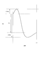
- FIG. 4 is a diagram illustrating an example of SOC variation of the secondary battery 210 according to travel of the vehicle 200.
- the vehicle 200 behaves as one of power running, coasting, and braking.
- the vehicle 200 is powered, the power charged in the secondary battery 210 is consumed, so the SOC of the secondary battery 210 decreases.
- the vehicle 200 is braked, the regenerative electric power from the braking is supplied to the secondary battery 210, so the SOC of the secondary battery 210 increases.
- the vehicle 200 consumes more power than usual when traveling on an ascending slope.
- the vehicle 200 consumes less power than usual when traveling on a downward slope, or regenerative power is supplied to the secondary battery 210. That is, the gradient of the route along which the vehicle 200 travels affects the increase and decrease of the SOC. Therefore, as shown in FIG. 4, the SOC of the secondary battery 210 may temporarily increase from the SOC before traveling, or the SOC of the secondary battery 210 may temporarily decrease from the SOC after traveling. is there.
- a traveling pattern when the vehicle 200 travels from the i-th charging point to the (i + 1) -th charging point is determined in advance.
- the SOC required to operate the vehicle 200 in the travel pattern varies depending on the number of passengers of the vehicle 200, the power consumption of the auxiliary machine according to the season, and the like.
- the current value calculation device 110 based on traveling under the worst condition, ⁇ E i , which is an SOC required for traveling from the i-th charging point to the i + 1-th charging point, and the vehicle 200
- the maximum value ⁇ Emax i and the minimum value ⁇ Emin i of the SOC variation of the secondary battery 210 related to the travel of the vehicle are specified in advance.
- the current value calculation device 110 can specify a current value that does not deviate from the operating range of the SOC even in the worst condition.
- step S12 when the current amount specifying unit 112 determines that the SOC of the secondary battery 210 is equal to or greater than the upper limit value of the operating range during traveling (step S12: YES), the current amount specifying unit 112 calculates in step S11. A predetermined penalty value is added to the evaluated value (step S13). On the other hand, if it is determined that the SOC of the secondary battery 210 does not exceed the upper limit value of the operating range during traveling (step S12: NO), the current amount specifying unit 112 does not add a penalty value to the evaluation value.
- the current amount specifying unit 112 charges the secondary battery 210 with the current amount ⁇ E i, j calculated by the current amount calculation unit 111 and moves the vehicle 200 from the i-th charging point to the i + 1-th charging point.
- the current amount identification unit 112 includes the j-th stage SOC, the SOC corresponding to the current amount ⁇ E i, j calculated by the current amount calculation unit 111, and the (i + 1) th charge from the i-th charging point.
- the minimum value of the fluctuation of the SOC of the secondary battery 210 is generally a negative number.
- step S14 when the current amount specifying unit 112 determines that the SOC of the secondary battery 210 is equal to or lower than the lower limit value of the operation range during traveling (step S14: YES), the current amount specifying unit 112 calculates in step S11. A predetermined penalty value is added to the evaluated value (step S15). On the other hand, when it is determined that the SOC of the secondary battery 210 is not equal to or lower than the lower limit value of the operation range during traveling (step S14: NO), the current amount specifying unit 112 does not add a penalty value to the evaluation value.
- the current amount specifying unit 112 obtains a current value obtained by dividing the current amount ⁇ E i, j calculated by the current amount calculating unit 111 by the allowable charging time T i at the i-th charging point. It is determined whether or not the upper limit value of the current value that can be supplied at the charging point is exceeded (step S16). When it is determined that the current value exceeds the upper limit value (step S16: YES), the current amount specifying unit 112 adds a predetermined penalty value to the evaluation value calculated in step S11 (step S17). On the other hand, if it is determined that the current value does not exceed the upper limit value (step S16: NO), the current amount specifying unit 112 does not add a penalty value to the evaluation value.
- the current amount specifying unit 112 has a value smaller than the evaluation value already stored in the evaluation value storage unit 113 in association with the combination of the i-th charging point and the j-th SOC. It is determined whether or not there is (step S18). When the evaluation value associated with the combination of the i-th charging point and the j-th SOC is not recorded in the evaluation value storage unit 113, the evaluation value calculated this time is based on the already stored evaluation value. Treated as being a small value.
- the current amount specifying unit 112 determines that the evaluation value calculated this time is smaller than the evaluation value already stored in the evaluation value storage unit 113 in association with the combination of the i-th charging point and the j-th SOC. If this is the case (step S18: YES), the evaluation value calculated this time is overwritten and recorded in the evaluation value storage unit 113 in association with the combination of the i-th charging point and the j-th SOC (step S19).
- the current value calculation unit 114 calculates the current value by dividing the current amount ⁇ E i, j calculated by the current amount calculation unit 111 by the allowable charging time T i at the i-th charging point.
- the current value calculation unit 114 overwrites and records the current value in the current value storage unit 115 in association with the combination of the i-th charging point and the j-th SOC (step S20).
- step S18 when the evaluation value calculated this time is not a value smaller than the evaluation value already stored in the evaluation value storage unit 113 in association with the combination of the i-th charging point and the j-th SOC (step S18: NO).
- the current amount specifying unit 112 and the current value calculating unit 114 do not record the evaluation value and the current value.
- the current value calculation device 110 executes the processes of steps S9 to S20 described above for all combinations of the start point SOC and the end point SOC, so that the current having the lowest evaluation value is obtained for each combination of the charge point and the start point SOC.
- the amount can be specified. That is, the current value calculated based on the current amount having the lowest evaluation value is recorded in the current value storage unit 115.
- the output unit 116 stores the charge stored in the current value storage unit 115. All combinations of the point, the SOC, and the current value are output to the charging control device 120 (step S21).
- a method of calculating an evaluation value by the current value calculation device 110 will be described using a specific example.
- the example described below is an example in which the current value is calculated for a route in which the SOC is divided into seven and two charging points are provided.
- the upper limit value of the current value that can be supplied by the charging device 10 provided at the charging point is 3 amperes.
- the allowable charging time at each charging point is 1 second.
- the SOC required for traveling from the first charging point to the second charging point is one stage of the SOC.
- the target SOC at the end point is the fifth stage SOC.
- the charging device 10 in the example can charge one stage of SOC by charging 1 ampere of current for 1 second.
- step S2 the current amount calculation unit 111 determines the amount of current necessary for charging in order to change the SOC at the end point to the fifth-stage SOC for each second-stage SOC at the second charging point. Is calculated.
- the amount of current required to charge the 0th stage SOC is 5 ampere seconds.
- the amount of current required to charge the SOC in the first stage is 4 ampere seconds.
- the amount of current required to charge the SOC in the second stage is 3 ampere seconds.
- the amount of current required to charge the SOC at the third stage is 2 ampere seconds.
- the amount of current required for charging the SOC at the fourth stage is 1 ampere second.
- the current amount specifying unit 112 calculates an evaluation value for each SOC stage in steps S3 to S5.
- the amount of current required for charging the SOC at the 0th stage and the 1st stage exceeds the upper limit of the amount of current that can be supplied by the charging apparatus 10. Therefore, the evaluation value related to the current amount is a sufficiently large value ( ⁇ ) to which the penalty value is added.
- the evaluation value relating to the amount of current necessary for charging the SOC in the second stage is 9.
- the evaluation value relating to the amount of current necessary for charging the SOC at the third stage is 4.
- the evaluation value relating to the amount of current necessary for charging the SOC in the fourth stage is 1. When the SOC of the secondary battery 210 is the fifth and sixth stage SOC, the evaluation value is zero.
- the current amount specifying unit 112 records these evaluation values in the evaluation value storage unit 113.
- the current amount calculation unit 111 selects the first charging point in step S8, and calculates the current amount and the evaluation value for each combination of the start point SOC and the end point SOC in step S9.
- the current amount calculation unit 111 selects the 0th stage SOC as the start point SOC and the 0th stage SOC as the end point SOC. In this case, the required amount of current is 1 ampere second.
- the evaluation value is a value obtained by adding ⁇ (a sufficiently large value) that is an evaluation value associated with the SOC at the 0th stage at the second charging point to 1 that is the current effective value.
- the current amount specifying unit 112 records the evaluation value in the evaluation value storage unit 113 in association with the first charging point and the 0th stage SOC.
- the current amount calculation unit 111 selects the 0th stage SOC as the start point SOC and the first stage SOC as the end point SOC. In this case, the required amount of current is 2 amp seconds.
- the evaluation value is a value obtained by adding ⁇ which is an evaluation value associated with the first-stage SOC at the second charging point to 4 which is an effective current value.
- the current amount calculation unit 111 selects the 0th stage SOC as the start point SOC and the second stage SOC as the end point SOC.
- the required amount of current is 3 amp seconds.
- the evaluation value is 18 which is a value obtained by adding 9 which is an evaluation value associated with the second-stage SOC at the second charging point to 9 which is an effective current value.
- the current amount specifying unit 112 evaluates the evaluation value in association with the first charging point and the 0th stage SOC. Overwrite recording is performed in the value storage unit 113.
- the current amount calculation unit 111 similarly selects the third to sixth stage SOCs as the end point SOC, and sequentially calculates the evaluation value.
- both values are larger than 18, overwriting is not recorded in the evaluation value storage unit 113.
- the current amount specifying unit 112 can record the evaluation value having the lowest value in the evaluation value storage unit 113.
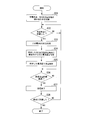
- FIG. 5 is a flowchart showing the operation of the charging control apparatus 120 according to the first embodiment of the present invention.
- the charging control unit 125 determines whether or not the vehicle 200 equipped with the charging control device 120 has reached the charging point (step S32). When the charging control unit 125 determines that the vehicle 200 has not reached the charging point (step S32: NO), the process returns to step S32 and continues to determine whether or not the charging point has been reached.
- the SOC specifying unit 123 includes the secondary battery mounted on the vehicle 200.
- the SOC of 210 is specified (step S33).
- the SOC specifying unit 123 may estimate the open circuit voltage from the voltage of the secondary battery 210 and specify the SOC corresponding to the open circuit voltage as the SOC of the secondary battery 210.
- the SOC specifying unit 123 may calculate the integrated value of the current charged and discharged by the secondary battery 210 and specify the SOC of the secondary battery 210 based on the integrated value.
- the current value specifying unit 124 reads from the current value storage unit 122 the current value associated with the combination of the charging point determined to have reached in step S32 and the SOC specified by the SOC specifying unit 123 (step S34).
- the charging control unit 125 causes the charging device 10 provided at the charging point to charge the secondary battery 210 with the current having the current value read by the current value specifying unit 124 (step S35).
- the charging control unit 125 determines whether or not the allowable charging time at the charging point has elapsed from the time when charging is started (step S36). When it is determined that the allowable charging time has not elapsed since the time when charging was started (step S36: NO), the charging control unit 125 continues charging. On the other hand, when it is determined that the allowable charging time has elapsed from the time when charging is started (step S36: YES), the charging control unit 125 stops charging by the charging device 10 (step S37).
- the charging control unit 125 determines whether or not the charging point where the vehicle 200 is currently stopped is the end point of the route (step S38). If the charging control unit 125 determines that the charging point at which the vehicle 200 is currently stopped is not the end point of the route (step S38: NO), the charging control unit 125 returns to step S32 and determines whether or not the next charging point has been reached. I do. On the other hand, when it is determined that the charging point where the vehicle 200 is currently stopped is the end point of the route (step S38: YES), the charging control unit 125 ends the charging control process.
- the charging control device 120 uses the current value obtained by dividing the amount of current that the vehicle 200 should charge the secondary battery 210 at the charging point by the allowable charging time. During the charging time, the secondary battery 210 is charged. As a result, the effective current value when charging the secondary battery 210 with the amount of current that the vehicle 200 should charge in the secondary battery 210 at the charging point can be minimized. The temperature of the secondary battery monotonously increases with respect to the current effective value. Therefore, the charging control device 120 can suppress the progress of deterioration based on the temperature of the secondary battery 210 by minimizing the current effective value.
- the charging control device 120 includes the current value storage unit 122 that stores a current value optimum for charging in association with each charging point and the SOC.
- the charging control device 120 performs charging at the current value stored in the current value storage unit 122. Thereby, the charging control apparatus 120 does not need to perform complicated calculations online, and can quickly identify an optimal current value.
- the current value at a certain charging point specified by the current value specifying unit 124 is determined so that the SOC of the secondary battery 210 when the vehicle 200 reaches the end point of the route becomes the predetermined target SOC. Is the current value obtained by dividing the optimal amount of current for charging the secondary battery 210 by the allowable charging time.
- the charging control device 120 controls charging according to the current value specified by the current value specifying unit 124, thereby minimizing heat generation of the secondary battery 210 at the end point of the path and setting the SOC to the target SOC. it can.
- the current value calculation device 110 calculates a current value based on the worst condition so as not to deviate from the operating width of the secondary battery 210.
- the current value calculation device 110 according to the second embodiment generates a relationship between the charging point, the SOC, and the current value for each state of the vehicle 200 or the secondary battery 210.
- Examples of the state of the vehicle 200 or the secondary battery 210 include, for example, the number of passengers of the vehicle 200, power consumption of auxiliary equipment (air conditioner, heating, etc.) according to the season, the degree of deterioration of the secondary battery 210, and the like.
- the current value specifying unit 124 of the charging control device 120 specifies the state of the vehicle 200 or the secondary battery 210 every time the charging point is reached.
- the current value specifying unit 124 specifies a current value associated with the state. At this time, the current value specifying unit 124 may correct the relationship between the charging point, the SOC, and the current value based on actually measured data corresponding to the time zone and season after the start of system operation.
- the present embodiment it is possible to appropriately reduce the SOC usage range and current effective value of the secondary battery 210 with respect to the state of the vehicle 200 and the secondary battery 210. Thereby, the progress of deterioration of the secondary battery 210 can be suppressed.
- the effect of reducing the effective current value is large in a state where a sudden change does not occur in the time width of one day, such as power consumption of the auxiliary machine according to the season and the degree of deterioration of the secondary battery 210.
- the charge amount that is a physical amount related to the state of charge of the secondary battery 210 is represented by the SOC, but is not limited thereto.
- the same effect can be obtained even when the charge amount is expressed by the capacity or open circuit voltage of the secondary battery 210.
- the charging control device 120 includes the current value storage unit 122, and the charging control unit 125 controls charging of the secondary battery 210 using the current value stored in the current value storage unit 122.
- the charging control unit 125 controls charging of the secondary battery 210 using the current value stored in the current value storage unit 122.
- a current amount storage unit that stores the current amount specified by the current amount specifying unit 112 may be provided.
- the current value specifying unit 124 may specify the current value by dividing the current amount read from the current amount storage unit by the allowable charging time.
- the current value calculation device 110 and the charge control device 120 are separately provided.
- the present invention is not limited to this, and a single device in which these are integrated may be used. In this case, the device may calculate an appropriate current value online without providing the current value storage unit 122.
- the current value calculation device 110 adds the penalty value after calculating the evaluation value based on the current effective value in the calculation of the evaluation value, but is not limited thereto.
- the current value calculation device 110 may add the evaluation value based on the current effective value after calculating the penalty value first.
- the current value calculation device 110 calculates the current amount and the evaluation value in order from the end points of a plurality of charging points on the route using the dynamic programming method, but is not limited thereto.
- the current value calculation device 110 is a method for deriving an optimal amount of current to set the SOC of the secondary battery 210 when the vehicle 200 reaches the end point of the route to the target SOC
- another optimal solution calculation method is used. It may be used.
- the current value calculation device 110 assumes that the operation schedule is greatly disturbed due to traffic jams, accidents, etc., and can select either the mode to apply this method or the mode to apply the conventional charging method depending on the situation. May be.
- the current value calculation device 110 and the charging control device 120 described above have a computer system inside.
- the operation of each processing unit described above is stored in a computer-readable recording medium in the form of a program, and the above processing is performed by the computer reading and executing this program.
- the computer-readable recording medium means a magnetic disk, a magneto-optical disk, a CD-ROM, a DVD-ROM, a semiconductor memory, or the like.
- the computer program may be distributed to the computer via a communication line, and the computer that has received the distribution may execute the program.
- the program may be for realizing a part of the above-described functions. Furthermore, what can implement
- DESCRIPTION OF SYMBOLS 100 ... Charge control system 110 ... Current value calculation apparatus 111 ... Current amount calculation part 112 ... Current amount specification part 113 ... Evaluation value storage part 114 ... Current value calculation part 115 ... Current value storage part 116 ... Output part 120 ... Charge control apparatus 121 ... Input unit 122 ... Current value storage unit 123 ... SOC identification unit 124 ... Current value identification unit 125 ... Charge control unit
Landscapes
- Engineering & Computer Science (AREA)
- Power Engineering (AREA)
- Life Sciences & Earth Sciences (AREA)
- Sustainable Development (AREA)
- Sustainable Energy (AREA)
- Transportation (AREA)
- Mechanical Engineering (AREA)
- Charge And Discharge Circuits For Batteries Or The Like (AREA)
- Secondary Cells (AREA)
- Electric Propulsion And Braking For Vehicles (AREA)
Abstract
充電制御装置は、車両が充電地点において二次電池に充電すべき電流量を当該充電地点における許容充電時間で除算して得られる電流値を、二次電池の充電状態に係る物理量である充電量に基づいて特定する。充電制御装置は、車両が充電地点に到達したときに、当該充電地点に設けられた充電装置に、特定した電流値の電流を、許容充電時間の間、二次電池へ充電させる。
Description
本発明は、複数の充電地点を有する経路上を走行する車両に備えられる二次電池の充電を制御する充電制御装置、充電制御方法及び充電制御システムに関する。
近年、環境問題への意識の高まりから、電動式車両の評価が高まっている。二次電池によって駆動する車両は、架線の敷設やメンテナンスの手間を減らし、さらに架線による景観への影響をなくすことができることから、実施に高い期待が寄せられている。
電動式車両に二次電池を導入する際、二次電池の劣化が課題となっている。具体的には、二次電池は劣化により新たな二次電池と交換する必要がある。二次電池の導入には、交換のためにコストがかかるという問題がある。二次電池の劣化の進行は、二次電池の充電率の使用幅や二次電池の温度の影響を受けることが知られている。
特許文献1には、経路における二次電池の充電率の増減が、最適な充電率を含む所定の範囲内となるように充電を行うことで、二次電池の充電率の使用幅に係る劣化の進行を抑制する技術が開示されている。
しかしながら、特許文献1には、二次電池の温度に基づく劣化の進行を抑制する技術については開示されていない。
本発明の目的は、上述した課題を解決する充電制御装置、充電制御方法及び充電制御システムを提供することにある。
本発明の目的は、上述した課題を解決する充電制御装置、充電制御方法及び充電制御システムを提供することにある。
一態様は、複数の充電地点を有する経路上を走行する車両に備えられる二次電池の充電を制御する充電制御装置である。充電制御装置は、電流値特定部と、充電制御部とを備える。前記電流値特定部は、前記車両が前記充電地点において前記二次電池に充電すべき電流量を当該充電地点における許容充電時間で除算して得られる電流値を、当該二次電池の充電状態に係る物理量である充電量に基づいて特定する。前記充電制御部は、前記車両が前記充電地点に到達したときに、当該充電地点に設けられた充電装置に、前記電流値特定部が特定した電流値の電流を、前記許容充電時間の間、前記車両の二次電池へ充電させる。
一態様は、上述した充電制御装置において、電流値記憶部を備える。前記電流値記憶部は、各充電地点において前記二次電池に充電すべき電流量を当該充電地点における許容充電時間で除算して得られる電流値を、当該充電地点に到達したときの前記二次電池の充電量ごとに記憶する。前記電流値特定部は、前記二次電池の現在の充電量に関連付けて前記電流値記憶部が記憶する電流値を、前記車両が前記充電地点において前記二次電池に充電すべき電流値として特定する。
一態様において、前記電流値特定部が特定するある充電地点における電流値は、前記車両が前記経路の終点に到達したときにおける前記二次電池の充電量を所定の目標値にするために、当該充電地点において前記二次電池を充電するのに最適な電流量を、前記許容充電時間で除算して得られる電流値である。
一態様において前記電流値特定部は、前記車両または前記二次電池の現在の状態に基づいて、前記二次電池に充電すべき電流の電流値を特定する。
一態様は、複数の充電地点を有する経路上を走行する車両に備えられる二次電池の充電を制御する充電制御方法である。充電制御方法は、前記車両が前記充電地点において前記二次電池に充電すべき電流量を当該充電地点における許容充電時間で除算して得られる電流値を、当該二次電池の充電状態に係る物理量である充電量に基づいて特定するステップを有する。充電制御方法は、前記車両が前記充電地点に到達したときに、当該充電地点に設けられた充電装置に、前記特定した電流値の電流を、前記許容充電時間の間、前記車両の二次電池へ充電させるステップを備える。
一態様において前記電流値を特定するステップにおいて特定する電流値は、前記車両が前記経路の終点に到達したときにおける前記二次電池の充電量を所定の目標値にするために、当該充電地点において前記二次電池を充電するのに最適な電流量を、前記許容充電時間で除算して得られる電流値である。
一態様は、複数の充電地点を有する経路上を走行する車両に備えられる二次電池の充電を制御する充電制御システムである。充電制御システムは、電流量特定部と電流値特定部と充電制御部を備える。前記電流量特定部は、前記充電地点及び前記二次電池の充電状態に係る物理量である充電量ごとに、前記車両が前記経路の終点に到達したときにおける前記二次電池の充電量を所定の目標値にするために、当該充電地点において前記二次電池を充電するのに最適な電流量を特定する。前記電流値特定部は、前記車両が充電地点に到達したときの前記二次電池の充電量に基づいて、前記電流量特定部が特定した電流量を前記充電地点における許容充電時間で除算して得られる電流値を特定する。前記充電制御部は、前記車両が前記充電地点に到達したときに、当該充電地点に設けられた充電装置に、前記電流値特定部が当該充電地点及び前記充電量について特定した電流値の電流を、前記許容充電時間の間、前記車両の二次電池へ充電させる。
一態様は、電流量算出部を備える。前記電流量算出部は、前記充電地点、当該充電地点における前記二次電池の充電量である始点充電量、及び当該充電地点の次の充電地点における前記二次電池の充電量である終点充電量との組み合わせごとに電流量を算出する。当該電流量は、前記二次電池の充電量が前記始点充電量である場合に、前記車両が前記次の充電地点に到達したときの当該二次電池の充電量を前記終点充電量にするために、当該充電地点における充電に要する電流量である。前記電流量特定部は、最適な電流量の特定をしていない充電地点について前記経路の終点側から順に、前記電流量算出部が算出した電流量ごとに、当該充電地点及び当該電流量に係る評価値として算出する。当該評価値は、当該電流量に単調増加する評価値と、当該電流量で前記二次電池を充電した場合に前記車両が当該充電地点の次の充電地点に到達したときの前記二次電池の充電量についての評価値とを加算した値である。前記電流量特定部は、当該評価値が最も小さい電流量を、最適な電流量として特定する。
二次電池の温度は、二次電池の電流実効値に対して単調増加し、また電流実効値は通電電流の二乗和に依存して決まる。少なくとも1つの態様によれば、充電制御部は、電流量特定部が特定した電流量を許容充電時間で除算して得られる電流を二次電池に供給する。そのため、充電制御部は、最小限の電流により二次電池を充電することができる。充電制御部は、二次電池の温度に基づく劣化の進行を抑制することができる。
《第1の実施形態》
以下、図面を参照しながら本発明の実施形態について詳しく説明する。
図1は、本発明の第1の実施形態に係る充電制御システム100の実施態様を示す概略図である。
充電制御システム100は、二次電池210の充電を制御するシステムである。二次電池210は、経路上を走行する車両200に備えられる。経路上には、充電装置10-1~10-N(以下、充電装置10-1~10-Nを総称する場合は、充電装置10と呼ぶ)を備えるN箇所の充電地点が設けられる。本実施形態において充電地点の1つは、経路の終点に設けられている。
充電制御システム100は、電流値算出装置110と、充電制御装置120とを備える。電流値算出装置110は、二次電池210の充電における適切な電流値を充電地点ごとに算出する。充電制御装置120は、電流値算出装置110が算出した電流値に基づいて二次電池210の充電を制御する。充電制御装置120は、車両200に搭載される。
以下、図面を参照しながら本発明の実施形態について詳しく説明する。
図1は、本発明の第1の実施形態に係る充電制御システム100の実施態様を示す概略図である。
充電制御システム100は、二次電池210の充電を制御するシステムである。二次電池210は、経路上を走行する車両200に備えられる。経路上には、充電装置10-1~10-N(以下、充電装置10-1~10-Nを総称する場合は、充電装置10と呼ぶ)を備えるN箇所の充電地点が設けられる。本実施形態において充電地点の1つは、経路の終点に設けられている。
充電制御システム100は、電流値算出装置110と、充電制御装置120とを備える。電流値算出装置110は、二次電池210の充電における適切な電流値を充電地点ごとに算出する。充電制御装置120は、電流値算出装置110が算出した電流値に基づいて二次電池210の充電を制御する。充電制御装置120は、車両200に搭載される。
図2は、本発明の第1の実施形態に係る充電制御システム100の構成を示す概略ブロック図である。
電流値算出装置110は、電流量算出部111、電流量特定部112、評価値記憶部113、電流値算出部114、電流値記憶部115及び出力部116を備える。
電流値算出装置110は、電流量算出部111、電流量特定部112、評価値記憶部113、電流値算出部114、電流値記憶部115及び出力部116を備える。
電流量算出部111は、充電地点と、当該充電地点における二次電池210のSOC(State Of Charge:充電率)(以下、始点SOCという)と、当該充電地点の次の充電地点における二次電池210のSOC(以下、終点SOCという)との組み合わせごとに、当該終点SOCを満たすために充電を要する電流量を算出する。本実施形態では、各段階について、上記計算を行う。当該段階は、二次電池210のSOCを運用幅の中で複数の段階に分割したものである。
電流量特定部112は、電流量算出部111が算出した電流量ごとに、当該電流量で二次電池210を充電することの適切さを示す評価値を算出する。電流量特定部112は、当該評価値に基づいて、二次電池210に充電すべき最適な電流量を特定する。評価値は値が小さいほど適切であることを示す。電流量特定部112は、ある充電地点及びある始点SOCについて算出した評価値のうち最も小さい値を、当該充電地点及び当該始点SOCに関連付けて、評価値記憶部113に記録する。
評価値記憶部113は、充電地点及び始点SOCの組み合わせに関連付けて、評価値を記憶する。
評価値記憶部113は、充電地点及び始点SOCの組み合わせに関連付けて、評価値を記憶する。
電流値算出部114は、充電地点及び始点SOCの組み合わせごとに、電流値を、当該充電地点及び当該始点SOCに関連付けて、電流値記憶部115に記録する。当該電流値は、電流量特定部112が特定した電流量をその充電地点における許容充電時間で除算して得られる電流値である。
電流値記憶部115は、充電地点及び始点SOCの組み合わせに関連付けて、二次電池210の充電に適切な電流値を記憶する。
出力部116は、電流値記憶部115が記憶する電流値を、充電制御装置120に出力する。
電流値記憶部115は、充電地点及び始点SOCの組み合わせに関連付けて、二次電池210の充電に適切な電流値を記憶する。
出力部116は、電流値記憶部115が記憶する電流値を、充電制御装置120に出力する。
充電制御装置120は、入力部121、電流値記憶部122、SOC特定部123、電流値特定部124及び充電制御部125を備える。
入力部121は、電流値算出装置110から充電地点及び始点SOCの組み合わせごとの電流値の入力を受け付ける。入力部121は、当該電流値を充電地点及び始点SOCに関連付けて電流値記憶部122に記録する。
電流値記憶部122は、充電地点及び始点SOCの組み合わせに関連付けて、二次電池210の充電に適切な電流値を記憶する。
電流値記憶部122は、充電地点及び始点SOCの組み合わせに関連付けて、二次電池210の充電に適切な電流値を記憶する。
SOC特定部123は、二次電池210のSOCを特定する。
電流値特定部124は、車両200が充電地点に到達したときに、当該充電地点と二次電池210のSOCとに関連付けられた電流値を、電流値記憶部122から読み出す。
充電制御部125は、車両200が充電地点に到達したときに、当該充電地点に設けられた充電装置10に、電流値特定部124が読み出した電流値の電流を、当該充電地点における許容充電時間の間、二次電池210へ充電させる。
電流値特定部124は、車両200が充電地点に到達したときに、当該充電地点と二次電池210のSOCとに関連付けられた電流値を、電流値記憶部122から読み出す。
充電制御部125は、車両200が充電地点に到達したときに、当該充電地点に設けられた充電装置10に、電流値特定部124が読み出した電流値の電流を、当該充電地点における許容充電時間の間、二次電池210へ充電させる。
つまり、本実施形態に係る電流値算出装置110は、予め充電地点及び二次電池210のSOCごとに、最適な充電を行うための電流値を算出しておく。そして、本実施形態に係る充電制御装置120は、充電地点に到達したときの二次電池210のSOCによって、予め算出された電流値の中から最適な電流値を特定し、当該電流値に基づいて二次電池210の充電を行う。
本実施形態に係る充電制御システム100の動作について説明する。
電流値算出装置110が電流値を算出する方法について説明する。図3は、本発明の第1の実施形態に係る電流値算出装置110の動作を示すフローチャートである。
電流値算出装置110は、二次電池210のSOCの段階を1つずつ選択する。電流値算出装置110は、選択した段階について、以下に示すステップS2~ステップS7に示す処理を行う(ステップS1)。以下、ステップS1で選択したSOCの段階を、j段階目と呼ぶ。
電流値算出装置110が電流値を算出する方法について説明する。図3は、本発明の第1の実施形態に係る電流値算出装置110の動作を示すフローチャートである。
電流値算出装置110は、二次電池210のSOCの段階を1つずつ選択する。電流値算出装置110は、選択した段階について、以下に示すステップS2~ステップS7に示す処理を行う(ステップS1)。以下、ステップS1で選択したSOCの段階を、j段階目と呼ぶ。
電流量算出部111は、電流量を算出する(ステップS2)。当該電流量は、終点に設けられた充電地点、すなわち第N番目の充電地点において二次電池210のSOCがj段階目のSOCである場合に、車両200が終点に到達したときの二次電池210のSOCを所定の目標SOC(目標値)にするために、当該充電地点において充電すべき電流量である。具体的には、電流量算出部111は、選択したSOCと目標SOCとの差に対応する電流量を算出する。
電流量特定部112は、電流量算出部111が算出した電流量に基づく電流実効値に許容充電時間を乗じた値を評価値として算出する(ステップS3)。具体的には、電流量特定部112は、式(1)に従って評価値を算出する。

FN,jは、第N番目の充電地点及びj段階目のSOCについて電流量算出部111が算出した電流量に対する評価値を示す。ΔEN,jは、第N番目の充電地点及びj段階目のSOCについて電流量算出部111が算出した電流量を示す。TNは、第N番目の充電地点の許容充電時間を示す。
電流量特定部112は、電流量算出部111が算出した電流量ΔEN,jを第N番目の充電地点の許容充電時間TNで除算して得られる電流値が、第N番目の充電地点において供給できる電流値の上限値を超えているか否かを判定する(ステップS4)。電流量特定部112は、電流値が上限値を超えていると判定した場合(ステップS4:YES)、ステップS3で算出した評価値に、所定のペナルティ値を加算する(ステップS5)。電流量特定部112は、ペナルティ値として、評価値となり得る値より大きい値など、評価値に対して十分に大きな値を用いる。他方、電流量特定部112は、電流値が上限値を超えていないと判定した場合(ステップS4:NO)、評価値に対するペナルティ値の加算を行わない。
電流量特定部112は、算出した評価値を、終点に設けられた充電地点とステップS1で選択したSOCとに関連付けて、評価値記憶部113に記録する(ステップS6)。
電流量特定部112は、算出した評価値を、終点に設けられた充電地点とステップS1で選択したSOCとに関連付けて、評価値記憶部113に記録する(ステップS6)。
電流値算出部114は、電流量算出部111が算出した電流量ΔEN,jを第N番目の充電地点の許容充電時間TNで除算して電流値を算出する。電流値算出部114は、当該電流値を、第N番目の充電地点及びj段階目のSOCの組み合わせに関連付けて、電流値記憶部115に記録する(ステップS7)。
電流値算出装置110は、全てのSOCの段階について上述したステップS1~ステップS7の処理を行うと、経路の終点側から順に、充電値記憶部に充電値を記録していない充電地点を1つずつ選択する。電流値算出装置110は、選択した充電地点について、以下に示すステップS9~ステップ20に示す処理を行う(ステップS8)。つまり、電流値算出装置110は、第N-1番目の充電地点、第N-2番目の充電地点、……第1番目の充電地点、の順に充電地点を選択する。以下、ステップS8で選択した充電地点を、第i番目の充電地点と呼ぶ。
電流値算出装置110は、ステップS8で充電地点を選択すると、さらに二次電池210の始点SOCの段階と終点SOCの段階とをそれぞれ1つずつ選択する。電流値算出装置110は、選択した段階の組み合わせについて、以下に示すステップS10~ステップS20に示す処理を行う(ステップS9)。以下、ステップS9で選択した始点SOCを第j番目のSOCと呼び、ステップS9で選択した終点SOCを第k番目のSOCと呼ぶ。
電流量算出部111は、ステップS8で選択した充電地点における始点SOCがj段階目のSOCである場合に、終点SOCをk段階目のSOCにするために、当該充電地点において充電すべき電流量を算出する(ステップS10)。具体的には、電流量算出部111は、j段階目のSOCとk段階目のSOCとの差に対応する電流量に、第i番目の充電地点から第i+1番目の充電地点まで走行するために必要な電流量を加算した電流量を算出する。
電流量特定部112は、評価値記憶部113から、第i+1番目の充電地点とk段階目のSOCとの組み合わせに関連付けられた評価値を読み出す。電流量特定部112は、ステップS10で電流量算出部111が算出した電流量ΔEi、jに対する評価値を算出する(ステップS11)。当該評価値は、電流量特定部112が読み出した評価値と、電流量算出部111が算出した電流量に基づく電流実効値に許容充電時間を乗じた値とを加算することで、算出される。具体的には、電流量特定部112は、式(2)に従って評価値を算出する。

次に、電流量特定部112は、電流量算出部111が算出した電流量ΔEi,jを二次電池210に充電して第i番目の充電地点から第i+1番目の充電地点まで車両200を走行させた場合に、走行中に二次電池210のSOCが運用範囲の上限値以上になるか否かを判定する(ステップS12)。具体的には、電流量特定部112は、j段階目のSOC、電流量算出部111が算出した電流量ΔEi,jに対応するSOC、及び第i番目の充電地点から第i+1番目の充電地点まで車両200を走行させる間の二次電池210のSOCの変動の最大値ΔEmaxi、を加算した値が、運用範囲の上限値以上であるか否かを判定する。
ここで、車両200の走行に係る二次電池210のSOCの変動について説明する。図4は、車両200の走行に係る二次電池210のSOCの変動の例を示す図である。
車両200は、ある区間を走行する際、力行、惰行または制動のいずれかの挙動をとる。車両200が力行すると、二次電池210に充電された電力を消費するため、二次電池210のSOCは減少する。他方、車両200が制動すると、制動による回生電力が二次電池210に供給されるため、二次電池210のSOCは増加する。車両200は、上り勾配を走行する場合に通常よりも多く電力を消費する。車両200は、下り勾配を走行する場合に通常より少ない電力を消費するか、回生電力が二次電池210に供給される。つまり車両200が走行する経路の勾配は、SOCの増減に影響を及ぼす。そのため、図4に示すように、二次電池210のSOCが一時的に走行前のSOCより増加することもあれば、二次電池210のSOCが一時的に走行後のSOCより減少することもある。
車両200は、ある区間を走行する際、力行、惰行または制動のいずれかの挙動をとる。車両200が力行すると、二次電池210に充電された電力を消費するため、二次電池210のSOCは減少する。他方、車両200が制動すると、制動による回生電力が二次電池210に供給されるため、二次電池210のSOCは増加する。車両200は、上り勾配を走行する場合に通常よりも多く電力を消費する。車両200は、下り勾配を走行する場合に通常より少ない電力を消費するか、回生電力が二次電池210に供給される。つまり車両200が走行する経路の勾配は、SOCの増減に影響を及ぼす。そのため、図4に示すように、二次電池210のSOCが一時的に走行前のSOCより増加することもあれば、二次電池210のSOCが一時的に走行後のSOCより減少することもある。
車両200が第i番目の充電地点から第i+1番目の充電地点まで走行する場合の走行パターンは予め決まっている。他方、当該走行パターンで車両200を運行するために要するSOCは、車両200の乗客数や季節に応じた補機の消費電力などによって異なる。本実施形態では、電流値算出装置110は、最悪条件での走行に基づいて、第i番目の充電地点から第i+1番目の充電地点までの走行に必要なSOCであるΔEi、並びに、車両200の走行に係る二次電池210のSOCの変動の最大値ΔEmaxi及び最小値ΔEminiを特定しておく。これにより、電流値算出装置110は、最悪条件でもSOCの運用幅を逸脱しないような電流値を特定することができる。
ステップS12において、電流量特定部112が、走行中に二次電池210のSOCが運用範囲の上限値以上になると判定した場合(ステップS12:YES)、電流量特定部112は、ステップS11で算出した評価値に所定のペナルティ値を加算する(ステップS13)。他方、電流量特定部112は、走行中に二次電池210のSOCが運用範囲の上限値以上にならないと判定した場合(ステップS12:NO)、評価値にペナルティ値を加算しない。
次に、電流量特定部112は、電流量算出部111が算出した電流量ΔEi,jを二次電池210に充電して第i番目の充電地点から第i+1番目の充電地点まで車両200を走行させた場合に、走行中に二次電池210のSOCが運用範囲の下限値以下になるか否かを判定する(ステップS14)。具体的には、電流量特定部112は、j段階目のSOC、電流量算出部111が算出した電流量ΔEi,jに対応するSOC、及び第i番目の充電地点から第i+1番目の充電地点まで車両200を走行させる間の二次電池210のSOCの変動の最小値ΔEmini、を加算した値が、運用範囲の下限値以下であるか否かを判定する。図4に示すように二次電池210のSOCの変動の最小値は一般的に負の数となる。
ステップS14において、電流量特定部112が、走行中に二次電池210のSOCが運用範囲の下限値以下になると判定した場合(ステップS14:YES)、電流量特定部112は、ステップS11で算出した評価値に所定のペナルティ値を加算する(ステップS15)。他方、電流量特定部112は、走行中に二次電池210のSOCが運用範囲の下限値以下にならないと判定した場合(ステップS14:NO)、評価値にペナルティ値を加算しない。
次に、電流量特定部112は、電流量算出部111が算出した電流量ΔEi,jを第i番目の充電地点の許容充電時間Tiで除算して得られる電流値が、第i番目の充電地点において供給できる電流値の上限値を超えているか否かを判定する(ステップS16)。電流量特定部112は、電流値が上限値を超えていると判定した場合(ステップS16:YES)、ステップS11で算出した評価値に、所定のペナルティ値を加算する(ステップS17)。他方、電流量特定部112は、電流値が上限値を超えていないと判定した場合(ステップS16:NO)、評価値にペナルティ値を加算しない。
次に、電流量特定部112は、今回算出した評価値が、第i番目の充電地点及びj段階目のSOCの組み合わせに関連付けて評価値記憶部113に既に記憶された評価値より小さい値であるか否かを判定する(ステップS18)。なお、第i番目の充電地点及びj段階目のSOCの組み合わせに関連付けられた評価値が評価値記憶部113に記録されていない場合には、今回算出した評価値は既に記憶された評価値より小さい値であるものとして扱われる。
電流量特定部112は、今回算出した評価値が、第i番目の充電地点及びj段階目のSOCの組み合わせに関連付けて評価値記憶部113に既に記憶された評価値より小さい値であると判定した場合(ステップS18:YES)、今回算出した評価値を、第i番目の充電地点及びj段階目のSOCの組み合わせに関連付けて評価値記憶部113に上書きして記録する(ステップS19)。電流値算出部114は、電流量算出部111が算出した電流量ΔEi,jを第i番目の充電地点の許容充電時間Tiで除算して電流値を算出する。電流値算出部114は、当該電流値を、第i番目の充電地点及びj段階目のSOCの組み合わせに関連付けて、電流値記憶部115に上書きして記録する(ステップS20)。
他方、今回算出した評価値が、第i番目の充電地点及びj段階目のSOCの組み合わせに関連付けて評価値記憶部113に既に記憶された評価値より小さい値でない場合は(ステップS18:NO)、電流量特定部112及び電流値算出部114は、評価値及び電流値の記録を行わない。
電流値算出装置110は、上述したステップS9~ステップS20の処理を、始点SOCと終点SOCの全ての組み合わせについて実行することで、充電地点と始点SOCの組み合わせごとに、最も評価値が低くなる電流量を特定することができる。つまり、電流値記憶部115には、最も評価値が低い電流量に基づいて算出された電流値が記録される。
電流値算出装置110が、全ての始点SOC及び終点SOCの組み合わせ、並びに全ての充電地点について上述したステップS8~ステップS20の処理を行うと、出力部116は、電流値記憶部115が記憶する充電地点、SOC及び電流値の組み合わせを、すべて充電制御装置120に出力する(ステップS21)。
具体的な例を用いて電流値算出装置110による評価値の算出方法について説明する。以下に説明する例は、SOCを7分割し、充電地点が2つ設けられた経路について、それぞれの電流値を計算する場合の例である。当該例において、充電地点に設けられる充電装置10が供給できる電流値の上限値が3アンペアである。当該例において、各充電地点における許容充電時間は1秒である。当該例において、第1番目の充電地点から第2番目の充電地点までの間の走行に必要なSOCは、SOCの1段階分である。当該例において、終点における目標SOCは5段階目のSOCである。当該例における充電装置10は、1アンペアの電流を1秒間充電することで、1段階分のSOCを充電することができる。
電流量算出部111は、ステップS2により、第2番目の充電地点について、0段階目~6段階目のSOCごとに、終点におけるSOCを5段階目のSOCにするために充電に必要な電流量を算出する。0段階目のSOCの充電に必要な電流量は5アンペア秒である。1段階目のSOCの充電に必要な電流量は4アンペア秒である。2段階目のSOCの充電に必要な電流量は3アンペア秒である。3段階目のSOCの充電に必要な電流量は2アンペア秒である。4段階目のSOCの充電に必要な電流量は1アンペア秒である。二次電池210のSOCが5段階目及び6段階目のSOCである場合は、充電は不要である。
次に、電流量特定部112は、ステップS3~S5により、SOCの段階ごとに、評価値を算出する。0段階目及び1段階目のSOCの充電に必要な電流量は、充電装置10が供給できる電流量の上限値を超える。そのため、当該電流量に係る評価値は、ペナルティ値が加算された十分に大きい値(α)となる。2段階目のSOCの充電に必要な電流量に係る評価値は9である。3段階目のSOCの充電に必要な電流量に係る評価値は4である。4段階目のSOCの充電に必要な電流量に係る評価値は1である。二次電池210のSOCが5段階目及び6段階目のSOCである場合は、評価値は0である。電流量特定部112は、これらの評価値を評価値記憶部113に記録する。
電流量算出部111は、ステップS8により、第1番目の充電地点を選択し、ステップS9により、始点SOCと終点SOCの組み合わせごとに、電流量及び評価値の算出を行う。
電流量算出部111は、始点SOCとして0段階目のSOCを選択し、終点SOCとして0段階目のSOCを選択する。この場合、必要な電流量は1アンペア秒である。評価値は、電流実効値である1に、第2番目の充電地点において0段階目のSOCに関連付けられた評価値であるα(十分に大きい値)を加算した値となる。ここで、電流量特定部112は、当該評価値を、第1番目の充電地点及び0段階目のSOCに関連付けて、評価値記憶部113に記録する。
電流量算出部111は、始点SOCとして0段階目のSOCを選択し、終点SOCとして0段階目のSOCを選択する。この場合、必要な電流量は1アンペア秒である。評価値は、電流実効値である1に、第2番目の充電地点において0段階目のSOCに関連付けられた評価値であるα(十分に大きい値)を加算した値となる。ここで、電流量特定部112は、当該評価値を、第1番目の充電地点及び0段階目のSOCに関連付けて、評価値記憶部113に記録する。
電流量算出部111は、始点SOCとして0段階目のSOCを選択し、終点SOCとして1段階目のSOCを選択する。この場合、必要な電流量は2アンペア秒である。評価値は、電流実効値である4に、第2番目の充電地点において1段階目のSOCに関連付けられた評価値であるαを加算した値となる。
次に、電流量算出部111は、始点SOCとして0段階目のSOCを選択し、終点SOCとして2段階目のSOCを選択する。この場合、必要な電流量は3アンペア秒である。評価値は、電流実効値である9に、第2番目の充電地点において2段階目のSOCに関連付けられた評価値である9を加算した値である18となる。ここで、当該評価値は、既に算出された評価値より小さい値であるため、電流量特定部112は、当該評価値を、第1番目の充電地点及び0段階目のSOCに関連付けて、評価値記憶部113に上書き記録する。
以下、電流量算出部111は、同様に終点SOCとして3段階目~6段階目のSOCを選択し、順次評価値を算出する。ただし、この例では何れも18より大きい値となるため、評価値記憶部113への上書き記録はされない。これにより、電流量特定部112は、最も低い値をとる評価値を、評価値記憶部113に記録することができる。
本実施形態に係る充電制御装置120の動作について説明する。図5は、本発明の第1の実施形態に係る充電制御装置120の動作を示すフローチャートである。
電流値算出装置110が、充電地点、SOC及び電流値の組み合わせを出力すると、充電制御装置120は当該情報の入力を受け付け、当該情報を電流値記憶部122に記録する(ステップS31)。
電流値算出装置110が、充電地点、SOC及び電流値の組み合わせを出力すると、充電制御装置120は当該情報の入力を受け付け、当該情報を電流値記憶部122に記録する(ステップS31)。
充電制御部125は、充電制御装置120を搭載する車両200が充電地点に到達したか否かを判定する(ステップS32)。充電制御部125が、車両200が充電地点に到達していないと判定した場合(ステップS32:NO)、ステップS32に戻り、充電地点に到達したか否かの判定を継続する。
他方、充電制御部125が、充電制御装置120を搭載する車両200が充電地点に到達したと判定した場合(ステップS32:YES)、SOC特定部123は、当該車両200に搭載された二次電池210のSOCを特定する(ステップS33)。具体的には、SOC特定部123は、二次電池210の電圧から開放電圧を推定し、当該開放電圧に対応するSOCを、当該二次電池210のSOCと特定しても良い。SOC特定部123は、二次電池210が充放電する電流の積算値を計算し、当該積算値に基づいて二次電池210のSOCを特定しても良い。
電流値特定部124は、ステップS32で到達したと判定された充電地点とSOC特定部123が特定したSOCとの組み合わせに関連付けられた電流値を、電流値記憶部122から読み出す(ステップS34)。充電制御部125は、充電地点に設けられた充電装置10に、電流値特定部124が読み出した電流値の電流で、二次電池210を充電させる(ステップS35)。
充電制御部125は、充電を開始した時刻から、当該充電地点における許容充電時間が経過したか否かを判定する(ステップS36)。充電制御部125は、充電を開始した時刻から許容充電時間が経過していないと判定した場合(ステップS36:NO)、充電を継続する。他方、充電制御部125は、充電を開始した時刻から許容充電時間が経過したと判定した場合(ステップS36:YES)、充電装置10による充電を停止させる(ステップS37)。
充電制御部125は、車両200が現時点で停車している充電地点が経路の終点であるか否かを判定する(ステップS38)。充電制御部125は、車両200が現時点で停車している充電地点が経路の終点でないと判定した場合(ステップS38:NO)、ステップS32に戻り、次の充電地点に到達したか否かの判定を行う。他方、充電制御部125は、車両200が現時点で停車している充電地点が経路の終点であると判定した場合(ステップS38:YES)、充電制御処理を終了する。
このように、本実施形態によれば、充電制御装置120は、車両200が充電地点において二次電池210に充電すべき電流量を、許容充電時間で除算して得られる電流値で、当該許容充電時間の間、二次電池210へ充電させる。これにより、車両200が充電地点において二次電池210に充電すべき電流量を二次電池210に充電する際の電流実効値を最小にすることができる。二次電池の温度は、電流実効値に対して単調増加する。そのため、充電制御装置120は、電流実効値を最小にすることにより、二次電池210の温度に基づく劣化の進行を抑制することができる。
本実施形態によれば、充電制御装置120は、各充電地点及びSOCに関連付けて、充電に最適な電流値を記憶する電流値記憶部122を備える。充電制御装置120は、電流値記憶部122が記憶する電流値での充電を行う。これにより、充電制御装置120は、オンラインで煩雑な計算を行う必要が無く、速やかに最適な電流値を特定することができる。
本実施形態において電流値特定部124が特定するある充電地点における電流値は、車両200が経路の終点に到達したときにおける二次電池210のSOCを所定の目標SOCにするために、当該充電地点において二次電池210を充電するのに最適な電流量を、許容充電時間で除算して得られる電流値である。これにより、充電制御装置120は、電流値特定部124が特定する電流値に従って充電を制御することで、経路の終点において二次電池210の発熱を最小にしてそのSOCを目標SOCにすることができる。
《第2の実施形態》
第1の実施形態に係る電流値算出装置110は、二次電池210の運用幅を逸脱しないように、最悪条件に基づいて電流値の算出を行う。他方、第2の実施形態に係る電流値算出装置110は、車両200または二次電池210の状態ごとに、充電地点、SOC及び電流値の関係を生成する。車両200または二次電池210の状態の例としては、例えば、車両200の乗客数、季節に応じた補機(エアコン、暖房など)の消費電力、二次電池210の劣化度などが挙げられる。充電制御装置120の電流値特定部124は、充電地点に到達するたびに、車両200または二次電池210の状態を特定する。電流値特定部124は、当該状態に関連付けられた電流値を特定する。
このとき、電流値特定部124は、システム運用開始後の時間帯や季節に応じた実測データをもとに、充電地点、SOC及び電流値の関係を補正してもよい。
第1の実施形態に係る電流値算出装置110は、二次電池210の運用幅を逸脱しないように、最悪条件に基づいて電流値の算出を行う。他方、第2の実施形態に係る電流値算出装置110は、車両200または二次電池210の状態ごとに、充電地点、SOC及び電流値の関係を生成する。車両200または二次電池210の状態の例としては、例えば、車両200の乗客数、季節に応じた補機(エアコン、暖房など)の消費電力、二次電池210の劣化度などが挙げられる。充電制御装置120の電流値特定部124は、充電地点に到達するたびに、車両200または二次電池210の状態を特定する。電流値特定部124は、当該状態に関連付けられた電流値を特定する。
このとき、電流値特定部124は、システム運用開始後の時間帯や季節に応じた実測データをもとに、充電地点、SOC及び電流値の関係を補正してもよい。
本実施形態によれば、車両200や二次電池210の状態に対して適切に二次電池210のSOC使用範囲及び電流実効値を削減することができる。これにより、二次電池210の劣化の進行を抑制することができる。特に、季節に応じた補機の消費電力や二次電池210の劣化度のような、1日の時間幅で急激な変化が生じない状態については、電流実効値の低減効果が大きいといえる。
以上、図面を参照してこの発明のいくつかの実施形態について詳しく説明してきたが、具体的な構成は上述のものに限られることはなく、この発明の要旨を逸脱しない範囲内において様々な設計変更等をすることが可能である。
例えば、上述した実施形態では、二次電池210の充電状態に係る物理量である充電量は、SOCによって表されるが、これに限られない。例えば、充電量が、二次電池210の容量や開放電圧などによって表されても、同様の効果を得ることができる。
例えば、上述した実施形態では、二次電池210の充電状態に係る物理量である充電量は、SOCによって表されるが、これに限られない。例えば、充電量が、二次電池210の容量や開放電圧などによって表されても、同様の効果を得ることができる。
また、上述した実施形態では、充電制御装置120が電流値記憶部122を備え、充電制御部125が、電流値記憶部122が記憶する電流値により二次電池210の充電を制御するが、これに限られない。例えば、電流値記憶部122に代えて、電流量特定部112が特定した電流量を記憶する電流量記憶部を備えても良い。電流値特定部124が、当該電流量記憶部から読み出した電流量を許容充電時間で除算することで、電流値を特定しても良い。
また、上述した実施形態では、電流値算出装置110と充電制御装置120とが別個に備えられるが、これに限られず、これらを一体とした1つの装置を用いても良い。この場合、電流値記憶部122を備えずに、当該装置がオンラインで適切な電流値を算出しても良い。
また、上述した実施形態では、電流値算出装置110は、評価値の算出において、電流実効値に基づく評価値を算出した後にペナルティ値を加算するが、これに限られない。例えば、電流値算出装置110は、先にペナルティ値を算出した後に電流実効値に基づく評価値を加算しても良い。
また、上述した実施形態では、電流値算出装置110は、動的計画法を用いて経路上の複数の充電地点の終点から順に電流量及び評価値の算出を行うが、これに限られない。電流値算出装置110は、車両200が経路の終点に到達したときの二次電池210のSOCを目標SOCにするために最適な電流量を導出する方法であれば、他の最適解算出法を用いても良い。
電流値算出装置110は、渋滞や事故などによる運行ダイヤの大幅な乱れを想定し、本手法を適用するモードと従来の充電手法を適用するモードのどちらかを、状況に応じて選択できるようにしても良い。
電流値算出装置110は、渋滞や事故などによる運行ダイヤの大幅な乱れを想定し、本手法を適用するモードと従来の充電手法を適用するモードのどちらかを、状況に応じて選択できるようにしても良い。
上述の電流値算出装置110及び充電制御装置120は内部に、コンピュータシステムを有している。そして、上述した各処理部の動作は、プログラムの形式でコンピュータ読み取り可能な記録媒体に記憶されており、このプログラムをコンピュータが読み出して実行することによって、上記処理が行われる。ここでコンピュータ読み取り可能な記録媒体とは、磁気ディスク、光磁気ディスク、CD-ROM、DVD-ROM、半導体メモリ等をいう。また、このコンピュータプログラムを通信回線によってコンピュータに配信し、この配信を受けたコンピュータが当該プログラムを実行するようにしても良い。
また、上記プログラムは、前述した機能の一部を実現するためのものであっても良い。さらに、前述した機能をコンピュータシステムにすでに記録されているプログラムとの組み合わせで実現できるもの、いわゆる差分ファイル(差分プログラム)であっても良い。
100…充電制御システム 110…電流値算出装置 111…電流量算出部 112…電流量特定部 113…評価値記憶部 114…電流値算出部 115…電流値記憶部 116…出力部 120…充電制御装置 121…入力部 122…電流値記憶部 123…SOC特定部 124…電流値特定部 125…充電制御部
Claims (8)
- 複数の充電地点を有する経路上を走行する車両に備えられる二次電池の充電を制御する充電制御装置であって、
前記車両が前記充電地点において前記二次電池に充電すべき電流量を当該充電地点における許容充電時間で除算して得られる電流値を、当該二次電池の充電状態に係る物理量である充電量に基づいて特定する電流値特定部と、
前記車両が前記充電地点に到達したときに、当該充電地点に設けられた充電装置に、前記電流値特定部が特定した電流値の電流を、前記許容充電時間の間、前記車両の二次電池へ充電させる充電制御部と
を備えることを特徴とする充電制御装置。 - 各充電地点において前記二次電池に充電すべき電流量を当該充電地点における許容充電時間で除算して得られる電流値を、当該充電地点に到達したときの前記二次電池の充電量ごとに記憶する電流値記憶部を備え、
前記電流値特定部は、前記二次電池の現在の充電量に関連付けて前記電流値記憶部が記憶する電流値を、前記車両が前記充電地点において前記二次電池に充電すべき電流値として特定する
ことを特徴とする請求項1に記載の充電制御装置。 - 前記電流値特定部が特定するある充電地点における電流値は、前記車両が前記経路の終点に到達したときにおける前記二次電池の充電量を所定の目標値にするために、当該充電地点において前記二次電池を充電するのに最適な電流量を、前記許容充電時間で除算して得られる電流値である
ことを特徴とする請求項1または請求項2に記載の充電制御装置。 - 前記電流値特定部は、前記車両または前記二次電池の現在の状態に基づいて、前記二次電池に充電すべき電流の電流値を特定する
ことを特徴とする請求項1から請求項3の何れか1項に記載の充電制御装置。 - 複数の充電地点を有する経路上を走行する車両に備えられる二次電池の充電を制御する充電制御方法であって、
前記車両が前記充電地点において前記二次電池に充電すべき電流量を当該充電地点における許容充電時間で除算して得られる電流値を、当該二次電池の充電状態に係る物理量である充電量に基づいて特定するステップと、
前記車両が前記充電地点に到達したときに、当該充電地点に設けられた充電装置に、前記特定した電流値の電流を、前記許容充電時間の間、前記車両の二次電池へ充電させるステップと
を備えることを特徴とする充電制御方法。 - 前記電流値を特定するステップにおいて特定する電流値は、前記車両が前記経路の終点に到達したときにおける前記二次電池の充電量を所定の目標値にするために、当該充電地点において前記二次電池を充電するのに最適な電流量を、前記許容充電時間で除算して得られる電流値である
ことを特徴とする請求項5に記載の充電制御方法。 - 複数の充電地点を有する経路上を走行する車両に備えられる二次電池の充電を制御する充電制御システムであって、
前記充電地点及び前記二次電池の充電状態に係る物理量である充電量ごとに、前記車両が前記経路の終点に到達したときにおける前記二次電池の充電量を所定の目標値にするために、当該充電地点において前記二次電池を充電するのに最適な電流量を特定する電流量特定部と、
前記車両が充電地点に到達したときの前記二次電池の充電量に基づいて、前記電流量特定部が特定した電流量を前記充電地点における許容充電時間で除算して得られる電流値を特定する電流値特定部と、
前記車両が前記充電地点に到達したときに、当該充電地点に設けられた充電装置に、前記電流値特定部が当該充電地点及び前記充電量について特定した電流値の電流を、前記許容充電時間の間、前記車両の二次電池へ充電させる充電制御部と
を備えることを特徴とする充電制御システム。 - 前記充電地点、当該充電地点における前記二次電池の充電量である始点充電量、及び当該充電地点の次の充電地点における前記二次電池の充電量である終点充電量との組み合わせごとに、前記二次電池の充電量が前記始点充電量である場合に、前記車両が前記次の充電地点に到達したときの当該二次電池の充電量を前記終点充電量にするために、当該充電地点における充電に要する電流量を算出する電流量算出部を備え、
前記電流量特定部は、最適な電流量の特定をしていない充電地点について前記経路の終点側から順に、前記電流量算出部が算出した電流量ごとに、当該電流量に単調増加する評価値と、当該電流量で前記二次電池を充電した場合に前記車両が当該充電地点の次の充電地点に到達したときの前記二次電池の充電量についての評価値とを加算した値を、当該充電地点及び当該電流量に係る評価値として算出し、当該評価値が最も小さい電流量を、最適な電流量として特定する
ことを特徴とする請求項7に記載の充電制御システム。
Priority Applications (2)
| Application Number | Priority Date | Filing Date | Title |
|---|---|---|---|
| SG11201506598PA SG11201506598PA (en) | 2013-04-01 | 2014-03-27 | Charge control device, charge control method, and charge control system |
| US14/767,800 US9457679B2 (en) | 2013-04-01 | 2014-03-27 | Charge control device, charge control method, and charge control system |
Applications Claiming Priority (2)
| Application Number | Priority Date | Filing Date | Title |
|---|---|---|---|
| JP2013076388A JP6086784B2 (ja) | 2013-04-01 | 2013-04-01 | 充電制御装置、充電制御方法及び充電制御システム |
| JP2013-076388 | 2013-04-01 |
Publications (1)
| Publication Number | Publication Date |
|---|---|
| WO2014162989A1 true WO2014162989A1 (ja) | 2014-10-09 |
Family
ID=51658287
Family Applications (1)
| Application Number | Title | Priority Date | Filing Date |
|---|---|---|---|
| PCT/JP2014/059015 Ceased WO2014162989A1 (ja) | 2013-04-01 | 2014-03-27 | 充電制御装置、充電制御方法及び充電制御システム |
Country Status (4)
| Country | Link |
|---|---|
| US (1) | US9457679B2 (ja) |
| JP (1) | JP6086784B2 (ja) |
| SG (1) | SG11201506598PA (ja) |
| WO (1) | WO2014162989A1 (ja) |
Families Citing this family (4)
| Publication number | Priority date | Publication date | Assignee | Title |
|---|---|---|---|---|
| KR101927180B1 (ko) * | 2016-10-25 | 2018-12-10 | 현대자동차 주식회사 | 구동 모터를 구비한 차량의 보조 배터리를 충전하는 방법 및 장치 |
| CN108661864B (zh) * | 2017-03-29 | 2022-03-22 | 通用电气公司 | 用于风轮机的齿轮箱组件的修理方法 |
| CN109291812A (zh) * | 2018-09-28 | 2019-02-01 | 上汽通用五菱汽车股份有限公司 | 电动汽车自动充电方法、装置和存储介质 |
| CN110466389A (zh) * | 2019-08-26 | 2019-11-19 | 广州小鹏汽车科技有限公司 | 车辆能量补充的推荐方法、装置、车辆以及机器可读介质 |
Citations (5)
| Publication number | Priority date | Publication date | Assignee | Title |
|---|---|---|---|---|
| JPH10290533A (ja) * | 1997-04-14 | 1998-10-27 | Honda Motor Co Ltd | バッテリ充電システム |
| JP2008092696A (ja) * | 2006-10-03 | 2008-04-17 | Toyota Motor Corp | 電動車両および車両充電システム |
| JP2008249633A (ja) * | 2007-03-30 | 2008-10-16 | Aisin Aw Co Ltd | 立寄施設案内システム及び立寄施設案内方法 |
| JP2010023785A (ja) * | 2008-07-24 | 2010-02-04 | Kawasaki Heavy Ind Ltd | 蓄電池駆動電車の給電システム |
| JP2012230027A (ja) * | 2011-04-27 | 2012-11-22 | Mitsubishi Motors Corp | 到着時刻予測システム |
Family Cites Families (5)
| Publication number | Priority date | Publication date | Assignee | Title |
|---|---|---|---|---|
| JP4220946B2 (ja) * | 2004-08-11 | 2009-02-04 | 三菱重工業株式会社 | 電気車両、架線レス交通システム及び架線レス交通システムの制御方法 |
| JP5647057B2 (ja) * | 2010-05-19 | 2014-12-24 | 株式会社日立製作所 | 充電装置、充電制御ユニット及び充電制御方法 |
| JP5931644B2 (ja) * | 2012-08-17 | 2016-06-08 | 株式会社東芝 | 充電管理システム |
| EP2865558B1 (en) * | 2013-10-24 | 2016-12-28 | Volvo Car Corporation | Method and system for controlling charging of an energy storage device |
| US9637017B2 (en) * | 2013-10-25 | 2017-05-02 | Korea Institute Of Energy Research | Power-sharing charging system, charging device, and method for controlling the same |
-
2013
- 2013-04-01 JP JP2013076388A patent/JP6086784B2/ja active Active
-
2014
- 2014-03-27 SG SG11201506598PA patent/SG11201506598PA/en unknown
- 2014-03-27 US US14/767,800 patent/US9457679B2/en active Active
- 2014-03-27 WO PCT/JP2014/059015 patent/WO2014162989A1/ja not_active Ceased
Patent Citations (5)
| Publication number | Priority date | Publication date | Assignee | Title |
|---|---|---|---|---|
| JPH10290533A (ja) * | 1997-04-14 | 1998-10-27 | Honda Motor Co Ltd | バッテリ充電システム |
| JP2008092696A (ja) * | 2006-10-03 | 2008-04-17 | Toyota Motor Corp | 電動車両および車両充電システム |
| JP2008249633A (ja) * | 2007-03-30 | 2008-10-16 | Aisin Aw Co Ltd | 立寄施設案内システム及び立寄施設案内方法 |
| JP2010023785A (ja) * | 2008-07-24 | 2010-02-04 | Kawasaki Heavy Ind Ltd | 蓄電池駆動電車の給電システム |
| JP2012230027A (ja) * | 2011-04-27 | 2012-11-22 | Mitsubishi Motors Corp | 到着時刻予測システム |
Also Published As
| Publication number | Publication date |
|---|---|
| SG11201506598PA (en) | 2015-11-27 |
| US20150375632A1 (en) | 2015-12-31 |
| JP2014204479A (ja) | 2014-10-27 |
| JP6086784B2 (ja) | 2017-03-01 |
| US9457679B2 (en) | 2016-10-04 |
Similar Documents
| Publication | Publication Date | Title |
|---|---|---|
| JP4788643B2 (ja) | ハイブリッド車両用の充放電制御装置および当該充放電制御装置用のプログラム | |
| CN104842797B (zh) | 电动汽车未来平均电耗预估、剩余续驶里程估计方法及系统 | |
| US8428804B2 (en) | In-vehicle charge and discharge control apparatus and partial control apparatus | |
| JP6441188B2 (ja) | 電池管理装置、電池システムおよびハイブリッド車両制御システム | |
| JP7079255B2 (ja) | ハイブリッド車のエネルギー消費を最適化するための方法 | |
| US10675983B2 (en) | Method and arrangement for determining a value of the state of energy of a battery in a vehicle | |
| CN114750743B (zh) | 混合动力车辆智能能量管理方法、系统、车辆及存储介质 | |
| US20150369867A1 (en) | Battery management terminal and battery management system | |
| CN105324270A (zh) | 用于以可调冷却阈值来对电池的冷却进行管理的方法 | |
| CN109204300A (zh) | 混合动力车辆及其行驶模式控制方法 | |
| JP6086784B2 (ja) | 充電制御装置、充電制御方法及び充電制御システム | |
| CN107450025B (zh) | 扭矩产生系统中的电池功率容量的估计 | |
| CN113853524A (zh) | 用于估计电池状态的方法 | |
| US20230271529A1 (en) | A method for controlling an energy storage system of a vehicle | |
| JP2009257124A (ja) | 車両走行制御装置 | |
| CN114932843B (zh) | 一种混合动力车辆的功率控制方法和相关装置 | |
| US20210146790A1 (en) | Intelligent energy management system for a vehicle and corresponding method | |
| JP2016516629A (ja) | ハイブリッドモータ推進プラントにおけるエネルギー等価係数を制御するための方法および装置 | |
| JP7749513B2 (ja) | Ev管理システム | |
| CN110875621B (zh) | 执行电驱动运输工具的组合式充电和电池平衡过程的方法 | |
| JP6228042B2 (ja) | 駆動制御システムおよび駆動制御システムを備えた移動体 | |
| KR102542958B1 (ko) | 차량 배터리 열화판단 제어방법 및 시스템 | |
| JP7363728B2 (ja) | 電気自動車の電池の管理装置 | |
| JP3350228B2 (ja) | 電鉄負荷予測装置 | |
| US12365252B2 (en) | Method for optimizing the driving strategy of a rail vehicle, data processing apparatus, computer program product, computer-readable medium, and a rail vehicle having an energy-storage device, energy-generating device, and data processing apparatus |
Legal Events
| Date | Code | Title | Description |
|---|---|---|---|
| 121 | Ep: the epo has been informed by wipo that ep was designated in this application |
Ref document number: 14779521 Country of ref document: EP Kind code of ref document: A1 |
|
| WWE | Wipo information: entry into national phase |
Ref document number: 14767800 Country of ref document: US |
|
| NENP | Non-entry into the national phase |
Ref country code: DE |
|
| 122 | Ep: pct application non-entry in european phase |
Ref document number: 14779521 Country of ref document: EP Kind code of ref document: A1 |