WO2014162483A1 - 医療用ポンプ、医療用ポンプシステム及び医療用ポンプの制御方法 - Google Patents
医療用ポンプ、医療用ポンプシステム及び医療用ポンプの制御方法 Download PDFInfo
- Publication number
- WO2014162483A1 WO2014162483A1 PCT/JP2013/059994 JP2013059994W WO2014162483A1 WO 2014162483 A1 WO2014162483 A1 WO 2014162483A1 JP 2013059994 W JP2013059994 W JP 2013059994W WO 2014162483 A1 WO2014162483 A1 WO 2014162483A1
- Authority
- WO
- WIPO (PCT)
- Prior art keywords
- information
- dose
- administration
- mode
- time
- Prior art date
- Legal status (The legal status is an assumption and is not a legal conclusion. Google has not performed a legal analysis and makes no representation as to the accuracy of the status listed.)
- Ceased
Links
Images





Classifications
-
- A—HUMAN NECESSITIES
- A61—MEDICAL OR VETERINARY SCIENCE; HYGIENE
- A61M—DEVICES FOR INTRODUCING MEDIA INTO, OR ONTO, THE BODY; DEVICES FOR TRANSDUCING BODY MEDIA OR FOR TAKING MEDIA FROM THE BODY; DEVICES FOR PRODUCING OR ENDING SLEEP OR STUPOR
- A61M5/00—Devices for bringing media into the body in a subcutaneous, intra-vascular or intramuscular way; Accessories therefor, e.g. filling or cleaning devices, arm-rests
- A61M5/14—Infusion devices, e.g. infusing by gravity; Blood infusion; Accessories therefor
- A61M5/142—Pressure infusion, e.g. using pumps
- A61M5/14212—Pumping with an aspiration and an expulsion action
- A61M5/14228—Pumping with an aspiration and an expulsion action with linear peristaltic action, i.e. comprising at least three pressurising members or a helical member
-
- A—HUMAN NECESSITIES
- A61—MEDICAL OR VETERINARY SCIENCE; HYGIENE
- A61M—DEVICES FOR INTRODUCING MEDIA INTO, OR ONTO, THE BODY; DEVICES FOR TRANSDUCING BODY MEDIA OR FOR TAKING MEDIA FROM THE BODY; DEVICES FOR PRODUCING OR ENDING SLEEP OR STUPOR
- A61M5/00—Devices for bringing media into the body in a subcutaneous, intra-vascular or intramuscular way; Accessories therefor, e.g. filling or cleaning devices, arm-rests
- A61M5/14—Infusion devices, e.g. infusing by gravity; Blood infusion; Accessories therefor
- A61M5/168—Means for controlling media flow to the body or for metering media to the body, e.g. drip meters, counters ; Monitoring media flow to the body
- A61M5/16831—Monitoring, detecting, signalling or eliminating infusion flow anomalies
- A61M2005/16863—Occlusion detection
-
- A—HUMAN NECESSITIES
- A61—MEDICAL OR VETERINARY SCIENCE; HYGIENE
- A61M—DEVICES FOR INTRODUCING MEDIA INTO, OR ONTO, THE BODY; DEVICES FOR TRANSDUCING BODY MEDIA OR FOR TAKING MEDIA FROM THE BODY; DEVICES FOR PRODUCING OR ENDING SLEEP OR STUPOR
- A61M2205/00—General characteristics of the apparatus
- A61M2205/50—General characteristics of the apparatus with microprocessors or computers
- A61M2205/502—User interfaces, e.g. screens or keyboards
-
- A—HUMAN NECESSITIES
- A61—MEDICAL OR VETERINARY SCIENCE; HYGIENE
- A61M—DEVICES FOR INTRODUCING MEDIA INTO, OR ONTO, THE BODY; DEVICES FOR TRANSDUCING BODY MEDIA OR FOR TAKING MEDIA FROM THE BODY; DEVICES FOR PRODUCING OR ENDING SLEEP OR STUPOR
- A61M2205/00—General characteristics of the apparatus
- A61M2205/50—General characteristics of the apparatus with microprocessors or computers
- A61M2205/52—General characteristics of the apparatus with microprocessors or computers with memories providing a history of measured variating parameters of apparatus or patient
Definitions
- the present invention relates to a medical pump such as an infusion pump used in a hospital or the like, a medical pump system, and a medical pump control method.
- Patent Document 1 when a drug solution is administered to a patient or the like in a hospital or the like and the dose or the like needs to be controlled with high accuracy, a syringe pump, an infusion pump, or the like is used (for example, Patent Document 1).
- an object of the present invention is to provide a medical pump, a medical pump system, and a control method for the medical pump that are easy to adjust the dosage of a medical solution or the like for each patient.
- the above object has multiple dose information that is a plurality of different dose information related to a drug to be administered to a patient, and corresponding administration that is administration time information corresponding to the multiple dose information.
- a medical pump having time information and configured to execute administration of the medicine based on the multiple dose information and the corresponding administration time information.
- corresponding administration time information (eg, low dose: 30 minutes and high dose: 30 minutes) which is administration time information corresponding to multiple dose information (eg, 10 mL / h, 20 mL / h)
- administration time information corresponding to multiple dose information (eg, 10 mL / h, 20 mL / h)
- multiple dose information eg, 10 mL / h, 20 mL / h
- the infusion pump will automatically administer the prescribed dose of the drug.
- the apparatus includes a plurality of pieces of dose information, group information including the corresponding administration time information, and repetition information of the group information, and the administration of the medicine is performed based on the group repetition information. It is characterized by being.
- the group information including the multiple dose information and the corresponding administration time information (for example, first at the low dose (30 minutes), then at the high dose (30 minutes), etc.) Repeated information, and is configured to execute administration of a medicine based on the set repeated information.
- multiple dose information which is different dose information for example, low dose information and high dose information, and combination information such as cycle information consisting of corresponding dose time information which is the dose time of these multiple dose information, etc.
- cycle information consisting of corresponding dose time information which is the dose time of these multiple dose information, etc.
- repetitive information for example, 10 times or the like
- the multiple dose information includes the dose information in which the dose increases or decreases stepwise over time.
- the multiple dose information includes the dose information in which the dose increases or decreases in stages as time passes, the drug is automatically administered by a predetermined dose every predetermined time. It can be increased or decreased, and an excessive burden on a medical worker or the like regarding a drug requiring such administration can be reduced.
- the multiple dose information is two pieces of the dose information, and the dose is increased or decreased as a predetermined time elapses, and the predetermined time is obtained by obtaining priority information. Regardless of the progress of the above, the dose is increased or decreased.
- the said structure it becomes the structure which performs the increase or decrease of the said dosage irrespective of progress of the said predetermined time by acquisition of priority information (for example, a patient's blood pressure value etc.).
- priority information for example, a patient's blood pressure value etc.
- the priority information is, for example, when the drug starts administration at a maximum blood pressure value of 60 mHg or more or stops administration at a maximum blood pressure value of 60 mHg or less, and this condition is met, the increase or decrease of the dose is reduced.
- the start or the like of the administration is increased or the stop or the like is decreased, so that more effective drug administration can be performed.
- it has a blockage detection unit that detects blockage of the flow of the medicine, and is configured to output alarm information based on the blockage information of the blockage detection unit.
- the said structure has the structure which has an obstruction
- the above object has multiple dose information that is a plurality of different dose information related to a drug to be administered to a patient, and corresponding administration that is administration time information corresponding to the multiple dose information.
- This is achieved by a method for controlling a medical pump characterized in that it has time information and is configured to execute administration of the medicine based on the multiple dose information and the corresponding administration time information.
- an object of the present invention is to provide a medical pump, a medical pump system, and a control method for the medical pump that are easy to adjust the dosage of a medical solution or the like for each patient.
- FIG. 1 It is the schematic which shows an infusion pump system which is a medical pump system which is a medical pump which has an infusion pump, for example.
- FIG. 1 It is a schematic block diagram which shows the main structures of the "infusion pump” shown in FIG.
- FIG. It is a schematic block diagram which shows the specific content of an interval mode related information storage part.
- FIG. 1 is a schematic view showing an infusion pump system 1 that is a medical pump system, for example, a medical pump system having an infusion pump 10.
- an infusion pump system 1 is disposed on the bedside of a patient or the like in a hospital or the like, and has a medicine bag 3 containing a medicine 2 containing medicine inside, a clamp 8, an infusion tube 4, etc. It has the "infusion pump 10" connected via.
- the infusion pump 10 is a device for accurately administering the drug solution 2 in the drug bag 3 to the patient P via the infusion tube 4, the indwelling needle or the indwelling catheter 5, and the drug 2 is supplied at a desired flow rate or the like. It becomes the structure which can be administered with respect to the patient P.
- FIG. 1 A schematic diagram of a device for accurately administering the drug solution 2 in the drug bag 3 to the patient P via the infusion tube 4, the indwelling needle or the indwelling catheter 5, and the drug 2 is supplied at a desired flow rate or the like. It becomes the structure which can be administered with respect to the patient P. FIG.
- the infusion pump 10 has a “display 11” for displaying various information, and a display change dial 12 that rotates (rotates) in both forward and reverse directions along the direction of the arrow R1. It is equipped. That is, by operating the display change dial 12, information displayed on the display 11 can be changed.
- the infusion pump 10 has a display selection that allows the user to select a screen for inputting and setting various parameters by variously changing the menu display by the OK button 13 or the display 11.
- Other input buttons 14 including a button 14a and a start / stop switch 14b are also arranged.
- the infusion pump 10 includes an upstream blockage sensor 15 and a downstream blockage sensor 16 which are blockage detection units, for example.
- the upstream occlusion sensor 15 is disposed on the drug bag 3 side that is upstream of the infusion pump 10
- the downstream occlusion sensor 16 is disposed on the downstream side of the infusion pump 10 that is on the patient P side. And it becomes the structure which can detect whether the flow of the chemical
- the infusion pump 10 has, as an additional function, a biological information acquisition device that acquires vital information such as blood pressure values such as blood pressure values, for example, a blood pressure monitor 6 and an electrocardiograph 7. Etc. can be connected.
- the sphygmomanometer 6 and the electrocardiogram measuring instrument 7 are connected to the patient P and have a function of continuously acquiring the blood pressure value and electrocardiogram data of the patient P.
- the infusion pump 10 shown in FIG. 1 has a computer, and the computer has a CPU (Central Processing Unit), a RAM (Random Access Memory), a ROM (Read Only Memory), etc., which are not shown in the figure. Connected via bus.
- CPU Central Processing Unit
- RAM Random Access Memory
- ROM Read Only Memory
- FIG. 2 is a schematic block diagram showing a main configuration of the “infusion pump 10” shown in FIG.
- the infusion pump 10 has a “pump control unit 20”.
- the pump control unit 20 controls the “pump main body 21” responsible for the basic operation of the infusion pump 10, and the above-mentioned “display 11”, “display change dial 12”, “OK button 13”, “ Other input buttons 14, “upper blockage sensor 15” and “lower blockage sensor 16” are controlled.
- the pump control unit 20 also controls the “timer 22” and the “alarm 23” shown in FIG. 2, and stores a storage unit and a processing unit (program) for various data related to the infusion pump 10 shown in FIG.
- the “interval mode related information storage unit 30”, “step mode related information storage unit 50”, “timer mode related information storage unit 70”, and the like are also controlled.
- 3, 4 and 5 are schematic blocks showing specific contents of the “interval mode related information storage unit 30”, “step mode related information storage unit 50” and “timer mode related information storage unit 70”, respectively. FIG. Specific contents thereof will be described later.
- FIGS. 6 to 15 are schematic flowcharts showing an operation example of the “infusion pump 10” according to the present embodiment.
- FIG. 7 to FIG. 9 are schematic flowcharts showing an operation example of “interval mode”
- FIG. 10 to FIG. 12 are schematic flowcharts showing an operation example of “step mode”.
- 15 is a schematic flowchart showing an operation example of the “timer mode”.
- the flow rate of the administered medicinal solution 2 is The case where it changes with time is demonstrated to an example.
- normal continuous administration normal mode; administration of a predetermined scheduled amount (mL) at a predetermined flow rate (mL / h)
- program injection modes three so-called program injection modes described below, The “interval mode”, “step mode”, and “timer mode” can be selected.
- the “interval mode” is the first dose (mL / h), which is the first dose (infusion amount) (mL / h), and one cycle as the administration parameter to be set and input. This set information is repeated with the execution time (minutes), interval time (minutes), and cycle number (times) as one set. The number of cycles, for example, the number of cycles is also specified by the prescription.
- the second dose (mL / h) is the final dose (mL / h).
- FIG. 16 is a schematic explanatory diagram showing the interval mode. That is, in the present embodiment, the second dose (mL / h) which is the final dose (mL / h) is 20 mL / h, the execution time of one cycle is 60 minutes, and the interval time 30 (minutes) is 1 As a set, the number of cycles is 10, and the first dose (mL / h), which is the first dose (mL / h), is 0 mL.
- the first dose (mL / h) and the second dose (mL / h) are examples of “multiple dose information”, and the first dose (mL / h) and the second dose (mL / h) Is an example of “corresponding administration time information”.
- the final dose (mL / h) is the second dose (mL / h) is 0 mL / h, the duration of one cycle is 60 minutes, and the interval time 30 (minutes) is one set.
- the first dose (mL / h), which is the first dose (mL / h), may be set to 20 mL / h 10 times.
- the “step mode” has a second dose (mL / h) that is the final dose (mL / h) as the administration parameter to be set and input, and the time until the first dose is reached. (Minutes), the number of steps (number) to reach the first dose.
- the first dose (mL / h), which is the first dose (mL / h), is a smaller dose than the second dose (mL / h).
- Multiple dose information eg, first dose (mL / h), second dose (mL / h), and these first dose (mL / h) and second dose (mL / h)
- the prescription information includes dosage information of each step in which the dosage changes, for example, increases step by step.
- FIG. 17 is a schematic explanatory diagram showing the step mode. That is, in the present embodiment, the first dose (mL / h) is 20 mL / h, the time (minutes) to reach the first dose is 75 minutes, and the number of steps to reach the first dose is 5 After the first dose (mL / h) reaches 20 mL / h, continuous administration at the first dose of 20 mL / h is performed.
- the “timer mode” is a final input dose (mL / h) as a dose parameter to be set and input, and biometric information is based on the final dose (mL / h).
- a condition for starting the administration for example, a condition is set so that the final dose (mL / h) is started on the condition that the blood pressure value has decreased by a predetermined value (the maximum blood pressure is 60 mmHg in FIG. 18A). is there. It has multi-dose information, no-dose information and dose information, and the dosage increases after the delay time information, which is the elapse of a predetermined time, and administration at the final dose (mL / h) starts. It is the composition to do.
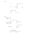
- FIG. 18A is a schematic explanatory diagram showing the timer mode.
- FIG. 18B shows an example of a configuration in which each of the two infusion pumps 100 and 10 administers different drugs to the same patient.
- the biometric information is set as a condition for starting administration at the final dose (mL / h).
- the condition that the blood pressure value has decreased to a predetermined value or less in FIG. 18A, the maximum blood pressure is 60 mmHg)
- To stop the administration by the infusion pump 100 that administers the first drug, and to start the administration by the infusion pump 10 that is the second infusion pump at the final dose (mL / h) Is set to Note that it is not always necessary to set administration in cooperation with biological information.
- the administration parameter to be set is the final dose (mL / h), and the biological information is a condition for starting administration with the final dose (mL / h).
- the first infusion pump 100 shows a “timer mode” in which an anticancer agent is initially administered and administration is stopped after a delay time has elapsed.
- FIG. 2 discloses a configuration in which the second infusion pump 10 starts administration of the pressor after the delay time has elapsed.
- blood pressure value information which is one of the biological information, which is one of the priority information
- FIG. 18B is a schematic explanatory diagram illustrating another example of the timer mode.
- FIG. 6 is a schematic flowchart showing the selection process of each mode.
- the nurse connects the drug bag 3 and the like to the “infusion pump 10” of FIG. 1 arranged beside the bed of the patient P, and infuses the patient P via the indwelling needle or the indwelling catheter 5.
- the tube 4 and the like are connected, and the infusion tube 4 is disposed in the “infusion pump 10”.
- the switch of the infusion pump 10 is turned on.
- the nurse visually recognizes the “display 11” and operates the display change dial 12 or the like to display it on the “display 11” as shown in FIG. 1 (B), and FIGS.
- One of “interval mode”, “step mode” and “timer mode” shown in the operation flow of a) is selected.
- step ST (hereinafter referred to as “ST”) 1 in FIG. 3, “display 11” of the infusion pump 10 has various modes of liquid feeding, “normal mode / interval mode (repetition (cycle))”. , Step mode (increase / decrease in drug stepwise), timer mode (start / stop administration after delay time elapses) "are displayed, and the nurse presses the display change dial 12, display selection button 14a, and confirm button One mode is selected by an operation of a certain “OK button 13”.
- the process proceeds to ST3.
- the selected mode is stored in the “dose mode selection result information storage unit 31” in FIG. That is, the “dose mode selection result information storage unit 31” stores information on the selected “normal mode”, “interval mode”, “step mode”, and “timer mode”.
- any one of “normal mode”, “interval mode”, “step mode”, and “timer mode” is controlled by the pump control unit 20.
- a screen for selecting is displayed on the “display 11” as shown in FIG.
- step mode it is determined whether or not the selected mode is “step mode” with reference to “dose mode selection result information storage unit 31”. If “step mode”, the process proceeds to ST6. move on. In ST6, the “step mode” is executed, and the operation will be described later.
- the process proceeds to ST7.
- ST7 it is determined whether or not the selected mode is “timer mode” with reference to “dose mode selection result information storage unit 31”. If “timer mode”, the process proceeds to ST8. The “timer mode” is executed, and the operation will be described later.
- the numerical value of the “final dose (mL / h)” to be set and input is set by rotating the display change dial 12. Therefore, after the numerical value is increased or decreased, the determined predetermined value is changed to the normal administration. Unlike the flow rate at the time, the flow rate is highlighted so that it is displayed on the display 11, and then, when the prescribed prescribed numerical value is reached, the OK button 13, which is a confirmation button, is pressed to The setting of the first dose (mL / h) as the numerical value of the dose (mL / h) is completed.
- ST13 a numerical value of the final dose (mL / h), for example, 20 mL / h is stored in the “interval mode information storage unit 32” of FIG.
- an input screen of “one cycle execution time (minutes)” is displayed on the display 11 under the control of the pump control unit 20.
- the nurse makes the numerical value highlighted on the display 11 under the control of the pump control unit 20 by the rotation operation of the display change dial 12, and inputs the setting “the execution time of one cycle (minutes)”
- the OK button 13 which is a confirmation button, if the predetermined prescribed numerical value is increased / decreased, the “one cycle execution time (minutes)” is set. Input is complete.
- an input screen of “interval time (minutes)” is displayed on the display 11 under the control of the pump control unit 20.
- the numerical value of “interval time (minutes)” to be inputted by the nurse is set on the screen so that the numerical value is highlighted on the display 11 under the control of the pump control unit 20 by the rotation operation of the display change dial 12.
- the OK button 13 which is a confirmation button, is pressed to complete the setting input of “one cycle execution time (minutes)” To do.
- ST18 it is determined whether or not the input of “interval time (minutes)” has been completed. If completed, the process proceeds to ST19.
- Information of “interval time (minutes)”, for example, 30 minutes (see FIG. 16) is stored in the “interval mode information storage unit 32” of FIG.
- an input screen of “repetition count (cycle count)” is displayed on the display 11 under the control of the pump control unit 20.
- the nurse turns the display change dial 12 so that the numerical value is highlighted on the display 11 under the control of the pump control unit 20, and the “repetition count (cycle count)” for inputting the setting is displayed.
- the numerical value is increased or decreased, and “repetition count (cycle count)” (for example, a numerical value of 10 cycles (see FIG. 16)) is displayed on the display 11 according to the doctor's prescription on this screen.
- the OK button 13 which is a confirmation button, is pressed, that is, how many times the repetition is executed is input as the number of cycles.
- ST21 it is determined whether or not the number of repetitions has been input. If the input has been completed, the process proceeds to ST22.
- “interval mode information storage unit 32” in FIG. 3 stores “repetition count (cycle count) information”, for example, 10 times.
- an “administration start time information” input screen is displayed on the display 11.
- the nurse inputs the time information for performing administration in the interval mode, for example, time information of 13:00 by operating the display change dial 12 or the like as required by the doctor on this screen.
- Step24 it is determined whether or not the input of the administration start time is completed.
- the process proceeds to ST25.
- “administration start time information”, for example, 13:00 is stored in the “interval mode information storage unit 32” of FIG.
- the “interval mode information storage unit 32” in FIG. 3 stores “20 mL / h” as the “final dose (mL / h)” shown in FIG. "For 60 minutes,” interval time (minutes) “for 30 minutes, and” repetition count (cycle count) “for” 10 times ".
- the process proceeds to ST27.
- the “interval administration operation processing unit (program) 33” in FIG. 3 operates, and the interval administration operation of the “infusion pump 10” is executed with reference to the “interval mode information storage unit 32”.
- “administration start time information” is not stored in the “interval mode information storage unit 32”
- the drug administration to the patient P in the interval mode is started by pressing the start / stop switch 14b.
- the final dose (mL / h) is “20 mL / h”
- the “one cycle execution time (minutes)” is 60 minutes
- the “interval time (minutes)” is 30 minutes.
- the administration of “10 times” is executed as the “repetition number (cycle number)”.
- the process proceeds to ST28.
- ST28 whether or not the “upper blockage sensor 15” and / or “lower blockage sensor 16” in FIG. 1 detects the blockage of the drug solution 2 in the “infusion tube 4” and outputs a blockage signal (blockage information).
- the infusion pump 10 detects it.
- the process proceeds to ST29, where the “alarm device 23” outputs an alarm signal to notify the nurse or the like that the infusion pump 10 has been blocked.
- the nurse in charge of the patient P can quickly know the occlusion of the infusion pump 10 and can take quick action, and can administer the drug solution 2 more safely.
- the process proceeds to ST30.
- ST30 it is determined whether the “interval administration operation processing unit (program) 33” of FIG. 2 has been operated and the “cycle count (for example, 10 times)” in the “interval mode information storage unit 32” has been executed. When it is executed 10 times, the process proceeds to ST31 and the liquid feeding operation of the infusion pump 10 is stopped. It should be noted that, while monitoring the living body such as the blood pressure value, when the blood pressure value falls outside the predetermined range, control may be performed to stop the liquid feeding operation of the infusion pump 10.
- step mode operation in ST7 will be described with reference to FIGS.
- a step mode in which the administration flow rate increases stepwise will be described as an example.
- the present invention is not limited to this and includes a case where the flow rate decreases stepwise.
- the final dose (mL / h), the final dose as input parameters to be set and input, which are all dose parameters in the step mode, are displayed on the display 11.
- the time (minutes) to reach the dose and the number of steps (number) to reach the final dose are displayed.
- the final dose (mL / h), the execution time of one cycle (min; minutes), the interval time (min; minutes), and the number of cycles are displayed in a list.
- an input screen for the final dose (mL / h) that is the flow rate of the drug solution 2 is displayed on the display 11.
- the nurse sets the numerical value of “final dose (mL / h)” to be set and input by rotating the display change dial 12 as prescribed by the doctor.
- the determined predetermined value is displayed on the display 11 in such a manner that the flow rate is highlighted, and then a predetermined button is a confirmation button.
- the OK button 13 is pressed, the setting input of the numerical value of “final dose (mL / h)” is completed.
- ST33 it is determined whether or not the input of the “final dose (mL / h)” flow rate has been completed.
- the process proceeds to ST34.
- the “step mode information storage unit 51” in FIG. 4 stores the flow rate of “final dose (mL / h)”, for example, 20 mL / h.
- the nurse increases or decreases the numerical value, and then determines the determined predetermined numerical value.
- the numerical value is highlighted and displayed on the display 11, and then, when a predetermined prescribed numerical value, for example, five times is displayed, an OK button 13 that is a confirmation button. By pressing, the setting input of “step count” 5 times is completed.
- the nurse makes the numerical value highlighted on the display 11 under the control of the pump control unit 20 by the rotation operation of the display change dial 12 on this screen, and inputs the setting “the final dose” In order to set the numerical value of “time to reach (minutes)”, by pressing the OK button 13 which is a confirmation button when the predetermined numerical value is increased / decreased, the “final dose” Setting input for “Time to reach (minutes)” is completed.
- step mode information storage unit 51 in FIG. 4 stores “time until reaching the final dose (minutes)”, for example, 75 minutes.
- an “administration start time information” input screen is displayed on the display 11.
- the nurse inputs time information for executing the “step mode” shown in FIG. 17, for example, 13:00 by operating the display change dial 12 or the like according to the doctor's prescription (“administration start” If the “time” is not set, the process proceeds to ST44, and the start / stop switch 14b is pressed to start administration of the drug to the patient P in the step mode.)
- Step42 it is determined whether or not the input of the administration start time is completed.
- the process proceeds to ST43 in FIG.
- “administration start time information”, for example, 13:00 is stored in the “step mode information storage unit 51” of FIG.
- the “step mode information storage unit 51” in FIG. 4 stores “20 mL / h” as the “final dose (mL / h)” shown in FIG. 75 minutes is stored as “time to reach (minutes)”.
- the infusion pump 10 of FIG. 1 can automatically administer the liquid medicine 2 in the step mode. For this reason, when the nurse performs step mode administration of the medicinal solution 2 to the patient P, it is not necessary to turn each infusion pump 10 at the time of each step to change the dose, etc. The system does not impose an excessive burden.
- the setting of the step mode in the infusion pump 10 suffices if a nurse or the like inputs necessary information in accordance with the display on the display 11, so that the setting is extremely easy, and lack of information input or the like hardly occurs. ing.
- the infusion pump 10 has a configuration in which it is easy to adjust the dose and the like of the drug solution P of the patient P.
- ST44 whether or not the current time is the “administration start time” based on “time administration device 22” in FIG. 2 and “administration start time information (eg, 13:00)” in the “steple mode information storage unit 51”. Determine whether.
- step administration operation processing unit (program) 55” in FIG. 4 operates, and the “step infusion pump 10” step administration operation is executed with reference to the “step mode information storage unit 51”.
- the nurse in charge of the patient P can quickly know the occlusion of the infusion pump 10 and can take quick action, and can administer the drug solution 2 more safely.
- the process proceeds to ST48.
- the “step administration operation processing unit (program) 55” of FIG. 4 operates to determine whether or not the execution of the step mode administration in the “step mode information storage unit 51” has been completed. When it is determined, the process proceeds to ST49, and the administration operation of the infusion pump 10 is stopped.
- control may be performed to stop the liquid feeding operation of the infusion pump 10.
- the “on-timer” or “off-timer” mode is an example of “a configuration in which the dose increases or decreases with the passage of a predetermined time”.
- ST62 the selected “on timer” or “off timer” is stored in the “timer mode information storage unit 71” of FIG.
- ST63 an input screen of, for example, delay time information (minutes), which is information on “final dose (mL / h)” and “elapsed predetermined elapsed time”, which are necessary items in the “on-timer”, is displayed on the display 11. Is displayed. Therefore, as shown in FIG. 18 (a), the nurse sets the “final dose (mL / h)” to “20 mL / h” and the “delay time information (minutes)” as shown in FIG. "Is entered as” 90 minutes ". That is, in the present embodiment, a medicine, for example, “pressor agent” is administered immediately after starting a predetermined administration start time, and “20 mL / h” is administered after 90 minutes.
- delay time information minutes
- ST64 the nurse or the like determines whether or not the input of “dose (dose)” and “delay time” has been completed, and when the input is completed, the process proceeds to ST65.
- “timer mode information storage unit 71” in FIG. 5 stores flow rate (mL / h) information of “dose (dose)”, for example, 20 mL / h and delay time information (for example, 90 minutes). Is done.
- the process proceeds to ST66.
- the “priority information” is information for starting or stopping the administration of the drug regardless of the delay time information, and in the present embodiment, it is the maximum blood pressure information (for example, 60 mHg) among the blood pressure values of the patient. is there. That is, as shown in FIG. 18 (a), when the patient's systolic blood pressure falls to 60 mHg or less, the administration is started regardless of the passage of delay time information of 90 minutes.
- the nurse or the like inputs “priority information” as “60 mHg or less” as shown in FIG.
- the process proceeds to ST67.
- ST67 it is determined whether or not the input of “priority information” by a nurse or the like is completed. If it is determined that the input is completed, the process proceeds to ST68.
- ST68 as “priority information”, for example, information indicating that “the patient's systolic blood pressure is 60 mHg or less” is stored in the “timer mode information storage unit 71” of FIG. By this input, “timer mode (on timer)” data as shown in FIG. 18A is input.
- an “administration start time information” input screen is displayed on display 11.
- the nurse operates the display change dial 12 etc. according to the doctor's prescription, the time for executing the “timer mode (on-timer)” shown in FIG. Enter with.
- ST70 it is determined whether or not the input of the administration start time is completed.
- the process proceeds to ST71.
- “administration start time information”, for example, 13:00 is stored in the “timer mode information storage unit 71” of FIG.
- the “timer mode information storage unit 71” in FIG. 5 stores “30 mL / h” as “dose”, “90 minutes” as “delay time information”, “priority information” shown in FIG. "The patient's systolic blood pressure is 60 mHg or less” and the “administration start time information” is "13:00".
- the infusion pump 10 of FIG. 1 can automatically administer the drug solution 2 such as a pressure increasing agent in the timer mode. For this reason, when the nurse performs step mode administration of the drug solution 2 to the patient P, it is not necessary to turn each infusion pump 10 to start the administration for “delay time information”. The system does not impose an excessive burden.
- the administration of the drug solution 2 as a pressor can be started even before the delay time elapses. Work that accelerates administration according to the blood pressure of the patient can also be reduced.
- the setting of the step mode in the infusion pump 10 suffices if a nurse or the like inputs necessary information in accordance with the display on the display 11, so that the setting is extremely easy, and lack of information input or the like hardly occurs. ing.
- the infusion pump 10 has a configuration in which it is easy to adjust the dose and the like of the drug solution P of the patient P.
- the current time is “delay time (90 from administration start time) based on“ administration start time information (eg, 13:00) ”in“ timer 22 ”and“ timer mode information storage unit 71 ”in FIG. Judge whether or not a minute) has elapsed.
- the process proceeds to S74.
- the “timer administration operation processing unit (program) 72” of FIG. 5 operates and refers to the “timer mode information storage unit 71”, which is a timer administration operation of the infusion pump 10, for example, a delay of 90 minutes
- a flow rate of “dose” of 20 mL / h is administered for a predetermined time.
- ST73 it is determined whether or not the maximum blood pressure value acquired from the “blood pressure monitor 6” of the patient in FIG. 1 corresponds to “maximum blood pressure of 60 mHg or less” that is “priority information”. Specifically, the “priority information determination processing unit (program) 73” in FIG. 5 operates, and the maximal blood pressure value of the sphygmomanometer 6 and the “priority information (patient maximal blood pressure value) of the“ timer mode information storage unit 71 ”. Is less than 60 mHg) ”to determine whether or not this is the case.
- the “timer administration operation processing unit (program) 72” in FIG. 5 operates, and referring to the “timer mode information storage unit 71” in FIG. 5, 20 mL which is the timer administration operation of the infusion pump.
- the administration of the chemical solution 2 of / h is executed before the delay time elapses. Therefore, administration of the medicinal solution 2 such as a pressor appropriate for the patient's condition can be automatically started, and the burden on the nurse or the like can be greatly reduced.
- the 3 performs the vital data such as the blood pressure value of the sphygmomanometer 6 and the electrocardiogram of the electrocardiograph 7 and the vital data reference range of the “vital data reference storage unit 28”. It is determined whether the blood pressure value obtained from the sphygmomanometer 6 or the like is within the reference range by comparing with the data.
- step 75 If it is determined in ST75 that the vital data such as the blood pressure value is not within the data range of the “vital data reference storage unit 35”, the process proceeds to ST76.
- ST76 as in ST26 described above, “alarm 23” in FIG. 3 operates to notify a nurse or the like that an abnormality has occurred in the vital data of patient P.
- the nurse in charge of the patient P can quickly know abnormalities such as vital data, can take quick measures, etc., and can safely administer the medicinal solution 2.
- the process proceeds to ST77.
- ST77 as in ST27 described above, the “upper blockage sensor 15” and / or “lower blockage sensor 16” in FIG. 1 detects the blockage of the drug solution 2 in the “infusion tube 4”, and a blockage signal (blockage information). Is detected by the infusion pump 10.
- the process proceeds to ST76 as described above, and the “alarm device 23” outputs an alarm signal to notify the nurse or the like that the blockage has occurred in the infusion pump 10.
- the nurse in charge of the patient P can quickly know the occlusion of the infusion pump 10 and can take quick action, and can administer the drug solution 2 more safely.
- the process proceeds to ST78.
- the “timer administration operation processing unit (program) 72” of FIG. 5 operates to determine whether or not the execution of the timer mode administration in the “timer mode information storage unit 71” has been completed. When it is determined, the process proceeds to ST79 and the operation of the infusion pump 10 is stopped.
- the timer mode is described as an example of an on-timer.
- the present invention is not limited to this, and as shown in FIG. 18 (b), an infusion pump 10 and two infusion pumps 100, different infusion pumps 100 can be operated in different modes (on-timer and off-timer).
- the infusion pump 100 is set so that an anticancer agent (for example, paclitaxel) is delivered, and the medicinal solution 2, for example, the infusion pump 10 in the above example, Set so that the pressurizer is delivered.
- an anticancer agent for example, paclitaxel
- the medicinal solution 2 for example, the infusion pump 10 in the above example
- the infusion pump 100 sets so that administration of a chemical
- the infusion pump 10 is set to administer the infusion after 90 minutes have elapsed in the on-timer.
- the infusion pump 100 stops administration of a chemical
- medical solution anticancer agent, paclitaxel
- the infusion pump 10 is set to start administration of a drug solution (pressor) when the patient's systolic blood pressure becomes 60 mHg or less.
- the present invention is not limited to the above-described embodiment.
- the infusion pump 10 has been described as an example of a medical device.
- the present invention is not limited to this, and the present invention can also be suitably applied to medical devices such as other liquid delivery devices such as a syringe pump.
- Interval administration operation processing unit program
- 50 ... Step mode related information storage unit, 51 ... Su Mode information storage unit, 55 ... step administration operation processing unit (program), 70 ... timer mode related information storage unit, 71 ... timer mode information storage unit, 72 ... timer administration operation processing unit (program) ), 73... Priority information determination processing unit (program)
Landscapes
- Health & Medical Sciences (AREA)
- Vascular Medicine (AREA)
- Engineering & Computer Science (AREA)
- Anesthesiology (AREA)
- Biomedical Technology (AREA)
- Heart & Thoracic Surgery (AREA)
- Hematology (AREA)
- Life Sciences & Earth Sciences (AREA)
- Animal Behavior & Ethology (AREA)
- General Health & Medical Sciences (AREA)
- Public Health (AREA)
- Veterinary Medicine (AREA)
- Infusion, Injection, And Reservoir Apparatuses (AREA)
Abstract
【課題】患者等毎の薬液等の投与量等の調整等を行い易い医療用ポンプ等を提供すること。 【解決手段】患者に対して投与する薬剤に関する複数の異なる投与量情報である複数投与量情報を有し、複数投与量情報に対応する投与時間情報である対応投与時間情報を有し、複数投与量情報と、対応投与時間情報に基づいて、薬剤2の投与を実行する構成となっている医療用ポンプ10。
Description
本発明は、例えば、病院等で使用する輸液ポンプ等の医療用ポンプ、医療用ポンプシステム及び医療用ポンプの制御方法に関するものである。
従来より、病院等で薬液を患者等に投与する場合で、その投与量等を精度良く制御する必要があるときは、シリンジポンプ、輸液ポンプ等を用いている(例えば、特許文献1)。
しかし、このような輸液ポンプ等を用いて投与量を制御する薬液は、患者の状態等に応じて、その投与量を時間の経過と共に変更等する必要があり、医療従事者等に過大な負担を強いるという問題があった。
また、病院等では、患者毎で異なるこのような時間経過に伴う投与量等の調整を、医療従事者が、その時間毎に、各輸液ポンプ等を回って、患者毎に調整しているため,特に負担が過大となっているという問題もあった。
また、病院等では、患者毎で異なるこのような時間経過に伴う投与量等の調整を、医療従事者が、その時間毎に、各輸液ポンプ等を回って、患者毎に調整しているため,特に負担が過大となっているという問題もあった。
そこで、本発明は、患者等毎の薬液等の投与量等の調整等を行い易い医療用ポンプ、医療用ポンプシステム及び医療用ポンプの制御方法を提供することを目的とする。
上記目的は、本発明にあっては、患者に対して投与する薬剤に関する複数の異なる投与量情報である複数投与量情報を有し、前記複数投与量情報に対応する投与時間情報である対応投与時間情報を有し、前記複数投与量情報と、前記対応投与時間情報に基づいて、前記薬剤の投与を実行する構成となっていることを特徴とする医療用ポンプにより達成される。
前記構成によれば、複数投与量情報(例えば、10mL/h、20mL/h)に対応する投与時間情報である対応投与時間情報(例えば、低用量時:30分と高用量時:30分)を有し、複数投与量情報と、対応投与時間情報に基づいて、薬剤の投与を実行する構成となっている。
このため、患者等に対する薬剤の投与量及び投与時間を予め医療従事者等が輸液ポンプ等の医療用ポンプに登録すれば、その後は、輸液ポンプ等が自動的に薬剤の投与量を所定の投与時間で変化等させて、患者等に投与する。
したがって、医療従事者等は、患者等に対する薬剤の投与量を時間の経過と共に変更等する必要があるときでも、その時間毎に、各患者毎の輸液ポンプ等を回って、調整する必要がなく、医療従事者等の過大な負担を回避することができる。また、患者毎の薬液等の投与量等の調整等を行い易い医療用ポンプとなる。
このため、患者等に対する薬剤の投与量及び投与時間を予め医療従事者等が輸液ポンプ等の医療用ポンプに登録すれば、その後は、輸液ポンプ等が自動的に薬剤の投与量を所定の投与時間で変化等させて、患者等に投与する。
したがって、医療従事者等は、患者等に対する薬剤の投与量を時間の経過と共に変更等する必要があるときでも、その時間毎に、各患者毎の輸液ポンプ等を回って、調整する必要がなく、医療従事者等の過大な負担を回避することができる。また、患者毎の薬液等の投与量等の調整等を行い易い医療用ポンプとなる。
好ましくは、前記複数投与量情報と、前記対応投与時間情報から成る組情報と、この組情報の繰り返し情報と、を備え、この組繰り返し情報に基づいて前記薬剤の投与を実行する構成となっていることを特徴とする。
前記構成によれば、複数投与量情報と、対応投与時間情報から成る組情報(例えば、最初に低用量時(30分)、次に高用量時(30分)等)と、この組情報の繰り返し情報と、を備え、この組繰り返し情報に基づいて薬剤の投与を実行する構成となっている。
このため、異なる投与量情報である複数投与量情報、例えば、低用量情報及び高用量情報と、これらの複数投与量情報の投与時間等である対応投与時間情報から成るサイクル情報等の組情報の繰り返し情報(例えば、10回等)に基づいて、薬剤の投与が実行される。したがって、同じ組情報の薬剤の投与の繰り返しを自動的に実行させることができ、医療従事者等の過大な負担を回避することができる。
このため、異なる投与量情報である複数投与量情報、例えば、低用量情報及び高用量情報と、これらの複数投与量情報の投与時間等である対応投与時間情報から成るサイクル情報等の組情報の繰り返し情報(例えば、10回等)に基づいて、薬剤の投与が実行される。したがって、同じ組情報の薬剤の投与の繰り返しを自動的に実行させることができ、医療従事者等の過大な負担を回避することができる。
好ましくは、前記複数投与量情報が時間の経過と共に段階的に投与量が増加又は減少する前記投与量情報を含むことを特徴とする。
前記構成によれば、複数投与量情報が時間の経過と共に段階的に投与量が増加又は減少する前記投与量情報を含むので、所定の時間毎に所定の投与量分だけ薬剤の投与を自動的に増加又は減少等させることができ、かかる投与が必要な薬剤についての医療従事者等の過大な負担を減少させることができる。
好ましくは、前記複数投与量情報が、2つの前記投与量情報であって、所定の時間の経過によって投与量が増加又は減少する構成となっていると共に、優先情報の取得により,前記所定の時間の経過にかかわらず、当該投与量の増加又は減少を実行する構成となっていることを特徴とする。
前記構成によれば、優先情報(例えば、患者の血圧値等)の取得により,前記所定の時間の経過にかかわらず、当該投与量の増加又は減少を実行する構成となっている。
このため、優先情報が、例えば、当該薬剤が最高血圧値60mHg以上で投与開始、又は最高血圧値60mHg以下で投与停止等であるときで、この条件に合致したときには、投与量の増加又は減少の所定の時間の経過の如何にかかわらず、投与の開始等の増加又は停止等の減少を行うので、より効果的な薬剤の投与が可能となる。
このため、優先情報が、例えば、当該薬剤が最高血圧値60mHg以上で投与開始、又は最高血圧値60mHg以下で投与停止等であるときで、この条件に合致したときには、投与量の増加又は減少の所定の時間の経過の如何にかかわらず、投与の開始等の増加又は停止等の減少を行うので、より効果的な薬剤の投与が可能となる。
好ましくは、前記薬剤の流れの閉塞を検知する閉塞検知部を有し、前記閉塞検知部の閉塞情報に基づき、警報情報を出力する構成となっていることを特徴とする。
前記構成によれば、薬剤の流れの閉塞を検知する閉塞検知部を有し、閉塞検知部の閉塞情報に基づき、警報情報を出力する構成となっている。
このため、薬剤の流れの閉塞による患者等への悪影響を迅速に対処することができる。
このため、薬剤の流れの閉塞による患者等への悪影響を迅速に対処することができる。
上記目的は、本発明にあっては、患者に対して投与する薬剤に関する複数の異なる投与量情報である複数投与量情報を有し、前記複数投与量情報に対応する投与時間情報である対応投与時間情報を有し、前記複数投与量情報と、前記対応投与時間情報に基づいて、前記薬剤の投与を実行する構成となっていることを特徴とする医療用ポンプの制御方法により達成される。
以上説明したように、本発明は、患者等毎の薬液等の投与量等の調整等を行い易い医療用ポンプ、医療用ポンプシステム及び医療用ポンプの制御方法を提供することを目的とする。
以下、この発明の好適な実施の形態を添付図面等を参照しながら、詳細に説明する。
尚、以下に述べる実施の形態は、本発明の好適な具体例であるから、技術的に好ましい種々の限定が付されているが、本発明の範囲は、以下の説明において特に本発明を限定する旨の記載がない限り、これらの態様に限られるものではない。
尚、以下に述べる実施の形態は、本発明の好適な具体例であるから、技術的に好ましい種々の限定が付されているが、本発明の範囲は、以下の説明において特に本発明を限定する旨の記載がない限り、これらの態様に限られるものではない。
図1は、医療用ポンプである例えば、輸液ポンプ10を有する医療用ポンプシステムである例えば、輸液ポンプシステム1を示す概略図である。
図1に示すように、輸液ポンプシステム1は、病院等の患者等のベッド脇等に配置され、その内部に薬剤が含まれる薬液2を収容する薬剤バッグ3と、クランプ8及び輸液チューブ4等を介して接続される「輸液ポンプ10」を有している。
図1に示すように、輸液ポンプシステム1は、病院等の患者等のベッド脇等に配置され、その内部に薬剤が含まれる薬液2を収容する薬剤バッグ3と、クランプ8及び輸液チューブ4等を介して接続される「輸液ポンプ10」を有している。
この輸液ポンプ10は、輸液チューブ4や留置針または留置カテーテル5等を介して薬剤バッグ3内の薬液2を、患者Pへ精度よく投与するための機器であり、薬剤2を所望の流量等で患者Pに対して投与することが可能な構成となっている。
また、輸液ポンプ10は、図1に示すように、各種情報を表示する「ディスプレイ11」を有すると共に、矢印R1方向に沿って、正逆双方向に回転(回動)する表示変更ダイヤル12が備わっている。
すなわち、この表示変更ダイヤル12を操作することで、ディスプレイ11に表示される情報を変更等することが可能な構成となっている。
また、図1に示すように、輸液ポンプ10には、OKボタン13やディスプレイ11によるメニュー表示を様々に遷移させて、各種パラメータの入力・設定するための画面の選択がきるようにする表示選択ボタン14a,開始/停止スイッチ14b等を含む他の入力ボタン14等も配置されている。
すなわち、この表示変更ダイヤル12を操作することで、ディスプレイ11に表示される情報を変更等することが可能な構成となっている。
また、図1に示すように、輸液ポンプ10には、OKボタン13やディスプレイ11によるメニュー表示を様々に遷移させて、各種パラメータの入力・設定するための画面の選択がきるようにする表示選択ボタン14a,開始/停止スイッチ14b等を含む他の入力ボタン14等も配置されている。
さらに、輸液ポンプ10は、閉塞検知部である例えば、上流閉塞センサ15及び下流閉塞センサ16を有している。
上流閉塞センサ15は、輸液ポンプ10の上流側である薬剤バッグ3側に配置され、下流閉塞センサ16は、患者P側である輸液ポンプ10の下流側に配置されている。
そして、これら2つのセンサにより、輸液チューブ4内の薬液2の流れが滞った状態となっているか否かを検知することが可能な構成となっている。
上流閉塞センサ15は、輸液ポンプ10の上流側である薬剤バッグ3側に配置され、下流閉塞センサ16は、患者P側である輸液ポンプ10の下流側に配置されている。
そして、これら2つのセンサにより、輸液チューブ4内の薬液2の流れが滞った状態となっているか否かを検知することが可能な構成となっている。
また、図1に示すように、輸液ポンプ10には、付加機能として、生体情報である例えば、血圧値等のバイタル情報を取得する生体情報取得装置である例えば、血圧計6及び心電図測定器7等が接続可能になっている。これら血圧計6及び心電図測定器7等は、患者Pに接続され、患者Pの血圧値や心電図データ等を継続的に取得する機能を備えた構成となっている。
また、図1に示す輸液ポンプ10等は、コンピュータを有し、コンピュータは、図示しないCPU(Central Processing Unit)、RAM(Random Access Memory)、ROM(Read Only Memory)等を有し、これらは、バスを介して接続されている。
図2は、図1に示す「輸液ポンプ10」の主な構成を示す概略ブロック図である。
図2に示すように、輸液ポンプ10は、「ポンプ制御部20」を有している。このポンプ制御部20は、輸液ポンプ10の基本的な動作等を担う「ポンプ本体部21」を制御する他、上述の「ディスプレイ11」、「表示変更ダイヤル12」、「OKボタン13」、「他の入力ボタン14」、「上部閉塞センサ15」及び「下部閉塞センサ16」を制御する。
図2に示すように、輸液ポンプ10は、「ポンプ制御部20」を有している。このポンプ制御部20は、輸液ポンプ10の基本的な動作等を担う「ポンプ本体部21」を制御する他、上述の「ディスプレイ11」、「表示変更ダイヤル12」、「OKボタン13」、「他の入力ボタン14」、「上部閉塞センサ15」及び「下部閉塞センサ16」を制御する。
また、ポンプ制御部20は、図2に示す「計時装置22」や「警報器23」も制御すると共に、図2に示す輸液ポンプ10に関する各種データの記憶部や処理部(プログラム)等を格納する「インターバルモード関連情報記憶部30」、「ステップモード関連情報記憶部50」及び「タイマーモード関連情報記憶部70」等も制御する構成となっている。
図3、図4及び図5は、それぞれ、「インターバルモード関連情報記憶部30」、「ステップモード関連情報記憶部50」及び「タイマーモード関連情報記憶部70」の具体的な内容を示す概略ブロック図である。これらの具体的な内容は後述する。
図3、図4及び図5は、それぞれ、「インターバルモード関連情報記憶部30」、「ステップモード関連情報記憶部50」及び「タイマーモード関連情報記憶部70」の具体的な内容を示す概略ブロック図である。これらの具体的な内容は後述する。
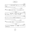
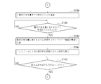
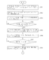
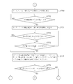
図6乃至図15は、本実施の形態に係る「輸液ポンプ10」の動作例を示す概略フローチャートである。具体的には、図7乃至図9は、「インターバルモード」の動作例を示す概略フローチャートであり、図10乃至図12は「ステップモード」の動作例を示す概略フローチャートであり、図13乃至図15は、「タイマーモード」の動作例を示す概略フローチャートである。
以下、図6乃至図15のフローチャートに従い、その動作等を説明しつつ同時に図1乃至図5の構成等についても説明する。
以下、図6乃至図15のフローチャートに従い、その動作等を説明しつつ同時に図1乃至図5の構成等についても説明する。
先ず、病院等の医療従事者等である例えば、看護師が入院患者Pに対して、医師の処方通りに薬剤を含む薬液2を投与する場合であって、その投与される薬液2の流量が時間で変化する場合を例に説明する。
本実施の形態では、通常の連続投与(通常モード;所定の流量(mL/h)で所定の予定量(mL)を投与)に加えて、以下で説明する3つのいわゆるプログラム注入モード、具体的には、「インターバルモード」、「ステップモード」及び「タイマーモード」を選択することが可能な構成となっている。
ここで、「インターバルモード」は、図16に示すように、設定入力する投与パラメータとして、最初の投与量(注入量)(mL/h)である第1の用量(mL/h)、1サイクルの実施時間(分),インターバル時間(分)、サイクル回数(回)を1組として、この組情報を繰り返す構成となっている。この繰り返し回数情報である例えば、サイクル回数も処方で特定される。第2の用量(mL/h)は、最終の投与量(mL/h)である。
本実施の形態では、通常の連続投与(通常モード;所定の流量(mL/h)で所定の予定量(mL)を投与)に加えて、以下で説明する3つのいわゆるプログラム注入モード、具体的には、「インターバルモード」、「ステップモード」及び「タイマーモード」を選択することが可能な構成となっている。
ここで、「インターバルモード」は、図16に示すように、設定入力する投与パラメータとして、最初の投与量(注入量)(mL/h)である第1の用量(mL/h)、1サイクルの実施時間(分),インターバル時間(分)、サイクル回数(回)を1組として、この組情報を繰り返す構成となっている。この繰り返し回数情報である例えば、サイクル回数も処方で特定される。第2の用量(mL/h)は、最終の投与量(mL/h)である。
図16は、インターバルモードを示す概略説明図である。
すなわち、本実施の形態では、最終の投与量(mL/h)である第2の用量(mL/h)が20mL/h,1サイクルの実施時間が60分,インターバル時間30(分)を1組として、サイクル回数が10回となっており、最初の投与量(mL/h)である第1の用量(mL/h)は0mLとなっている。第1の用量(mL/h)、第2の用量(mL/h)が「複数投与量情報」の一例であり、第1の用量(mL/h)、第2の用量(mL/h)を投与する時間等が「対応投与時間情報」の一例となっている。
なお、最終の投与量(mL/h)である第2の用量(mL/h)が0mL/h,1サイクルの実施時間が60分,インターバル時間30(分)を1組として、サイクル回数を10回、最初の投与量(mL/h)である第1の用量(mL/h)を20mL/hのように設定する場合もある。
すなわち、本実施の形態では、最終の投与量(mL/h)である第2の用量(mL/h)が20mL/h,1サイクルの実施時間が60分,インターバル時間30(分)を1組として、サイクル回数が10回となっており、最初の投与量(mL/h)である第1の用量(mL/h)は0mLとなっている。第1の用量(mL/h)、第2の用量(mL/h)が「複数投与量情報」の一例であり、第1の用量(mL/h)、第2の用量(mL/h)を投与する時間等が「対応投与時間情報」の一例となっている。
なお、最終の投与量(mL/h)である第2の用量(mL/h)が0mL/h,1サイクルの実施時間が60分,インターバル時間30(分)を1組として、サイクル回数を10回、最初の投与量(mL/h)である第1の用量(mL/h)を20mL/hのように設定する場合もある。
「ステップモード」は、図17に示すように、設定入力する投与パラメータとして、最終の投与量(mL/h)である第2の用量(mL/h),第1の用量に達するまでの時間(分),第1の用量に達するまでのステップ数(数)である。
最初の投与量(mL/h)である第1の用量(mL/h)は、第2の用量(mL/h)よりも小さい用量である。
複数投与量情報である、例えば、第1の用量(mL/h)、第2の用量(mL/h)及び、これら第1の用量(mL/h)及び第2の用量(mL/h)との間で段階的に投与量が変化、例えば、増加する各ステップの投与量情報を含む処方情報である。
図17は、ステップモードを示す概略説明図である。
すなわち、本実施の形態では、第1の用量(mL/h)が20mL/h,第1の用量に達するまでの時間(分)が75分、第1の用量に達するまでのステップ数は5であり、第1の用量(mL/h)が20mL/hに達した後は、第1の用量である20mL/hでの連続投与となる。
最初の投与量(mL/h)である第1の用量(mL/h)は、第2の用量(mL/h)よりも小さい用量である。
複数投与量情報である、例えば、第1の用量(mL/h)、第2の用量(mL/h)及び、これら第1の用量(mL/h)及び第2の用量(mL/h)との間で段階的に投与量が変化、例えば、増加する各ステップの投与量情報を含む処方情報である。
図17は、ステップモードを示す概略説明図である。
すなわち、本実施の形態では、第1の用量(mL/h)が20mL/h,第1の用量に達するまでの時間(分)が75分、第1の用量に達するまでのステップ数は5であり、第1の用量(mL/h)が20mL/hに達した後は、第1の用量である20mL/hでの連続投与となる。
また、「タイマーモード」は、図18(a)に示すように、設定入力する投与パラメータとして、最終の投与量(mL/h)とし、生体情報を、最終の投与量(mL/h)による投与を開始する条件とし、例えば、血圧値が所定低下したことを条件(図18(a)では最高血圧が60mmHg)に、最終の投与量(mL/h)を開始するように設定するものである。
複数投与量情報である投与量無し情報及び用量情報を有し、所定の時間の経過である遅遅延時間情報経過後に投与量が増加し、最終の投与量(mL/h)での投与を開始する構成となっている。
図18(a)は、タイマーモードを示す概略説明図である。
複数投与量情報である投与量無し情報及び用量情報を有し、所定の時間の経過である遅遅延時間情報経過後に投与量が増加し、最終の投与量(mL/h)での投与を開始する構成となっている。
図18(a)は、タイマーモードを示す概略説明図である。
一方、図18(b)では、2つの輸液ポンプ100、10のそれぞれが、異なる薬剤を同じ患者に投与する構成の例を示すものである。生体情報を、最終の投与量(mL/h)による投与を開始する条件とし、例えば、血圧値が所定値以下に低下したことを条件(図18(a)では最高血圧が60mmHgになった場合)に、第1の薬剤を投与している輸液ポンプである100による投与を停止させ、第2の輸液ポンプである輸液ポンプ10による投与を、最終の投与量(mL/h)で開始するように設定するものである。
なお、必ずしも、生体情報に連携させて、投与するように設定しなくてもよい。
設定入力する投与パラメータとして、最終の投与量(mL/h)とし、生体情報を、最終の投与量(mL/h)による投与を開始する条件としている。
なお、必ずしも、生体情報に連携させて、投与するように設定しなくてもよい。
設定入力する投与パラメータとして、最終の投与量(mL/h)とし、生体情報を、最終の投与量(mL/h)による投与を開始する条件としている。
具体的には、第1の輸液ポンプ100は、抗がん剤を、当初投与し、遅延時間経過後に投与を停止する「タイマーモード」を示す。また、同図では、第2の輸液ポンプ10が、昇圧剤の投与を、遅延時間経過後に開始する構成を開示している。
また、同図では優先情報である例えば、生体情報の1つである血圧値情報が,例えば、最高血圧60mHg以下になったときに、これに基づいて、遅延時間未経過であっても、第1の輸液ポンプ100は、抗がん剤の投与を停止し、第2の輸液ポンプ10は昇圧剤の投与を開始する構成が開示されている。
図18(b)は、タイマーモードの他の例を示す概略説明図である。
また、同図では優先情報である例えば、生体情報の1つである血圧値情報が,例えば、最高血圧60mHg以下になったときに、これに基づいて、遅延時間未経過であっても、第1の輸液ポンプ100は、抗がん剤の投与を停止し、第2の輸液ポンプ10は昇圧剤の投与を開始する構成が開示されている。
図18(b)は、タイマーモードの他の例を示す概略説明図である。
図6は、これらの各モードの選択工程を示す概略フローチャートである。
先ず、看護師は、患者Pのベッド脇に配置された図1の「輸液ポンプ10」に薬剤バッグ3等を接続すると共に、患者Pに対しては、留置針または留置カテーテル5を介して輸液チューブ4等を接続し、この輸液チューブ4を「輸液ポンプ10」内に配置する。
また、輸液ポンプ10のスイッチをON状態とする。さらに、看護師は、「ディスプレイ11」を視認し、表示変更ダイヤル12等を操作して、図1(B)に示すように「ディスプレイ11」に表示させ、図16、図17及び図18(a)の動作フローに示す、「インターバルモード」「ステップモード」及び「タイマーモード」のいずれかを選択する。
先ず、看護師は、患者Pのベッド脇に配置された図1の「輸液ポンプ10」に薬剤バッグ3等を接続すると共に、患者Pに対しては、留置針または留置カテーテル5を介して輸液チューブ4等を接続し、この輸液チューブ4を「輸液ポンプ10」内に配置する。
また、輸液ポンプ10のスイッチをON状態とする。さらに、看護師は、「ディスプレイ11」を視認し、表示変更ダイヤル12等を操作して、図1(B)に示すように「ディスプレイ11」に表示させ、図16、図17及び図18(a)の動作フローに示す、「インターバルモード」「ステップモード」及び「タイマーモード」のいずれかを選択する。
先ず、図3のステップST(以下「ST」とする。)1では、輸液ポンプ10の「ディスプレイ11」には、送液の各種モードである、「通常モード/インターバルモード(繰り返し(サイクル))、ステップモード(段階的に薬剤が増加/減少)、タイマーモード(遅延時間経過後の投与開始/投与停止)」が表示され、看護師は、表示変更ダイヤル12、表示選択ボタン14a、確定ボタンである「OKボタン13」の操作で、いずれかのモードを選択する。
ST2では「モードを選択したか?」否かが判断され、ST2で、モードの選択がなされると、ST3へ進む。
ST3では、選択されたモードを、図3の「用量モード選択結果情報記憶部31」に記憶させる。すなわち、この「用量モード選択結果情報記憶部31」には、選択された「通常モード」、「インターバルモード」、「ステップモード」及び「タイマーモード」の情報が記憶される。
ST3では、選択されたモードを、図3の「用量モード選択結果情報記憶部31」に記憶させる。すなわち、この「用量モード選択結果情報記憶部31」には、選択された「通常モード」、「インターバルモード」、「ステップモード」及び「タイマーモード」の情報が記憶される。
次いで、ST4では、「用量モード選択結果情報記憶部31」を参照して、ポンプ制御部20の制御により、「通常モード」、「インターバルモード」、「ステップモード」及び「タイマーモード」のいずれかを選択する画面を「ディスプレイ11」に、図1(B)のように表示される。
ST5へ進み、ST5では、「用量モード選択結果情報記憶部31」を参照して、選択されたモードが「ステップモード」であるか否かが判断され、「ステップモード」の場合は、ST6へ進む。ST6では、「ステップモード」が実行されるが、その動作については後述する。
一方、ST5で、選択されたモードが「ステップモード」でないときは、ST7へ進む。ST7では、「用量モード選択結果情報記憶部31」を参照して、選択されたモードが「タイマーモード」であるか否かが判断され、「タイマーモード」の場合は、ST8へ進む。「タイマーモード」が実行されるが、その動作については後述する。
一方、ST7で、選択されたモードが「タイマーモード」でないときは、ST9へ進む。ST9では、「インターバルモード」の動作が実行される。
<インターバルモードの説明>
以下、図7乃至図9を用いて、ST9の「インターバルモード動作」について説明する。
図7のST11では、ポンプ制御部20の制御により、ディスプレイ11にまず、図1(C)のように、インターバルモードのすべての投与パラメータである、最終の投与量(mL/h)である第2の用量(mL/h)、1サイクルの実施時間(min;分)、インターバル時間(min;分)、サイクル回数が一覧で表示される。
以下、図7乃至図9を用いて、ST9の「インターバルモード動作」について説明する。
図7のST11では、ポンプ制御部20の制御により、ディスプレイ11にまず、図1(C)のように、インターバルモードのすべての投与パラメータである、最終の投与量(mL/h)である第2の用量(mL/h)、1サイクルの実施時間(min;分)、インターバル時間(min;分)、サイクル回数が一覧で表示される。
次いで、ST12へ進む。ST12では、表示変更ダイヤル12の回転動作により、設定入力する「最終の投与量(mL/h)」の数値を設定するため、数値を増減させたのち、決定した所定の値を、通常の投与時の流量とは異なり、流量がハイライト表示されるようにして、ディスプレイ11に表示させ、その後、処方された所定の数値であると、確定ボタンである、OKボタン13を押すことで、最終の投与量(mL/h)の数値を第1の用量(mL/h)の設定入力が完了する。
ST12で、入力が完了したときは、ST13へ進む。ST13では、図3の「インターバルモード情報記憶部32」に例えば、最終の投与量(mL/h)の数値、例えば20mL/hを記憶させる。
次いで、ST14へ進む。ST14では、ポンプ制御部20の制御によりディスプレイ11に「1サイクルの実施時間(分)」の入力画面が表示される。
看護師は、この画面で、表示変更ダイヤル12の回転動作により、ポンプ制御部20の制御により、ディスプレイ11に数値をハイライト表示されるようにし、設定入力する「1サイクルの実施時間(分)」の数値を設定するため、数値を増減させた後、処方された所定の数値であると、確定ボタンである、OKボタン13を押すことで、「1サイクルの実施時間(分)」の設定入力が完了する。
看護師は、この画面で、表示変更ダイヤル12の回転動作により、ポンプ制御部20の制御により、ディスプレイ11に数値をハイライト表示されるようにし、設定入力する「1サイクルの実施時間(分)」の数値を設定するため、数値を増減させた後、処方された所定の数値であると、確定ボタンである、OKボタン13を押すことで、「1サイクルの実施時間(分)」の設定入力が完了する。
次に、ST15へ進む。「1サイクルの実施時間(分)」の入力が完了したか否かを判断し、完了したときは、ST16へ進む。
次に、ST17に進む。ST17では、ポンプ制御部20の制御によりディスプレイ11に「インターバル時間(分)」の入力画面が表示される。
看護師は、この画面で、表示変更ダイヤル12の回転動作により、ポンプ制御部20の制御により、ディスプレイ11に数値をハイライト表示されるようにし、設定入力する「インターバル時間(分)」の数値を設定するため、数値を増減させた後、処方された所定の数値であると、確定ボタンである、OKボタン13を押すことで、「1サイクルの実施時間(分)」の設定入力が完了する。ST18では、「インターバル時間(分)」の入力が完了したか否かを判断し、完了したときは、ST19へ進む。
図3の「インターバルモード情報記憶部32」に「インターバル時間(分)」の情報、例えば30分(図16参照)を記憶する。
看護師は、この画面で、表示変更ダイヤル12の回転動作により、ポンプ制御部20の制御により、ディスプレイ11に数値をハイライト表示されるようにし、設定入力する「インターバル時間(分)」の数値を設定するため、数値を増減させた後、処方された所定の数値であると、確定ボタンである、OKボタン13を押すことで、「1サイクルの実施時間(分)」の設定入力が完了する。ST18では、「インターバル時間(分)」の入力が完了したか否かを判断し、完了したときは、ST19へ進む。
図3の「インターバルモード情報記憶部32」に「インターバル時間(分)」の情報、例えば30分(図16参照)を記憶する。
次いで、ST20へ進む。ST20では、ポンプ制御部20の制御によりディスプレイ11に「繰り返し回数(サイクル回数)」の入力画面が表示される。
看護師は、この画面で、表示変更ダイヤル12の回転動作により、ポンプ制御部20の制御により、ディスプレイ11に数値をハイライト表示されるようにし、設定入力する「繰り返し回数(サイクル回数)」の数値を設定するため、数値を増減させ、この画面で医師の処方通りに、「繰り返し回数(サイクル回数)」(例えば、サイクル回数として10回(図16参照)という数値)を、ディスプレイ11にハイライト表示させた後、所定の数値が表示されると、確定ボタンである、OKボタン13を押すことで、すなわち、繰り返しを何回実行させるかをサイクル回数として入力する。
看護師は、この画面で、表示変更ダイヤル12の回転動作により、ポンプ制御部20の制御により、ディスプレイ11に数値をハイライト表示されるようにし、設定入力する「繰り返し回数(サイクル回数)」の数値を設定するため、数値を増減させ、この画面で医師の処方通りに、「繰り返し回数(サイクル回数)」(例えば、サイクル回数として10回(図16参照)という数値)を、ディスプレイ11にハイライト表示させた後、所定の数値が表示されると、確定ボタンである、OKボタン13を押すことで、すなわち、繰り返しを何回実行させるかをサイクル回数として入力する。
次いで、図8のST21へ進む。ST21では、繰り返し回数の入力が完了したか否かを判断し、入力が完了したときは、ST22へ進む。ST22では、図3の「インターバルモード情報記憶部32」に「繰り返し回数(サイクル回数)情報」例えば、10回が記憶される。
次いで、ST23へ進む。ST23では、ディスプレイ11に「投与開始時刻情報」入力画面を表示される。
看護師は、この画面で医師の処方通りに、必要に応じて、インターバルモードでの投与を実行する時刻、例えば、13時00分という時刻情報を表示変更ダイヤル12等の操作により入力する。
看護師は、この画面で医師の処方通りに、必要に応じて、インターバルモードでの投与を実行する時刻、例えば、13時00分という時刻情報を表示変更ダイヤル12等の操作により入力する。
次いで、ST24へ進む。ST24では、投与開始時刻の入力が完了したか否かが判断され、入力が完了したときは、ST25へ進む。ST25では、図3の「インターバルモード情報記憶部32」に「投与開始時刻情報」、例えば、13時00分が記憶される。
これらの工程で、図3の「インターバルモード情報記憶部32」には、図16で示す「最終の投与量(mL/h)」として「20mL/h」、「1サイクルの実施時間(分)」として60分、「インターバル時間(分)」として30分、「繰り返し回数(サイクル回数)」として「10回」の情報が記憶される。
次いで、図8のST26へ進む。ST26では、図2の「計時装置22」と「インターバルモード情報記憶部32」の「投与開始時刻情報(例えば、13時00分)」に基づき、現在時刻が「投与開始時刻」であるか否かを判断する。
ST26で、「投与開始時刻」が到来したと判断されたときは、ST27へ進む。ST27では、図3の「インターバル投与動作処理部(プログラム)33」が動作し、「インターバルモード情報記憶部32」を参照して、「輸液ポンプ10」のインターバル投与動作が実行される。
なお、「インターバルモード情報記憶部32」に「投与開始時刻情報」が記憶されていない状態の場合、開始/停止スイッチ14bを押すことで、患者Pへのインターバルモードでの薬剤の投与が開始される。
すなわち、図16に示すように、最終の投与量(mL/h)」として「20mL/h」、「1サイクルの実施時間(分)」として60分、「インターバル時間(分)」として30分、「繰り返し回数(サイクル回数)」として「10回」の投与が実行される。
なお、「インターバルモード情報記憶部32」に「投与開始時刻情報」が記憶されていない状態の場合、開始/停止スイッチ14bを押すことで、患者Pへのインターバルモードでの薬剤の投与が開始される。
すなわち、図16に示すように、最終の投与量(mL/h)」として「20mL/h」、「1サイクルの実施時間(分)」として60分、「インターバル時間(分)」として30分、「繰り返し回数(サイクル回数)」として「10回」の投与が実行される。
次いで、ST28へ進む。ST28では、図1の「上部閉塞センサ15」及び/又は「下部閉塞センサ16」が「輸液チューブ4」内の薬液2の閉塞を検知し、閉塞信号(閉塞情報)を出力したか否かを輸液ポンプ10が検知する。
ST28で、閉塞信号を検知したときは、ST29へ進み、「警報器23」が警報信号を出力し、輸液ポンプ10に閉塞が発生したことを看護師等に報知する。
ST28で、閉塞信号を検知したときは、ST29へ進み、「警報器23」が警報信号を出力し、輸液ポンプ10に閉塞が発生したことを看護師等に報知する。
したがって、当該患者Pの担当看護師等は速やかに、輸液ポンプ10の閉塞を知ることができ、迅速な対応等をすることができ、より安全な薬液2の投与が可能となる。
一方、ST28で、「上部閉塞センサ15」及び/又は「下部閉塞センサ16」が「輸液チューブ4」内の薬液2の閉塞信号(閉塞情報)を出力しないときは、ST30へ進む。
ST30では、図2の「インターバル投与動作処理部(プログラム)33」が動作し、「インターバルモード情報記憶部32」内の「サイクル回数(例えば、10回)」を実行したか否かを判断し、10回実行されたときは、ST31へ進み、輸液ポンプ10の送液動作を停止させる。
なお、血圧値等の生体をモニターしながら、血圧値が所定の範囲外になった場合は、輸液ポンプ10の送液動作を停止させるような制御を行うようにしてもよい。
ST30では、図2の「インターバル投与動作処理部(プログラム)33」が動作し、「インターバルモード情報記憶部32」内の「サイクル回数(例えば、10回)」を実行したか否かを判断し、10回実行されたときは、ST31へ進み、輸液ポンプ10の送液動作を停止させる。
なお、血圧値等の生体をモニターしながら、血圧値が所定の範囲外になった場合は、輸液ポンプ10の送液動作を停止させるような制御を行うようにしてもよい。
<ステップモードの説明>
次いで、図10乃至図12を用いて、ST7の「ステップモード動作」について説明する。
なお、本実施の形態では、段階的に投与流量が増加するステップモードを例に説明するが、上述のように、本発明はこれに限らず、段階的に減少する場合も含まれる。
次いで、図10乃至図12を用いて、ST7の「ステップモード動作」について説明する。
なお、本実施の形態では、段階的に投与流量が増加するステップモードを例に説明するが、上述のように、本発明はこれに限らず、段階的に減少する場合も含まれる。
先ず、図10のST31では、ポンプ制御部20の制御により、ディスプレイ11にまず、ステップモードのすべての投与パラメータである、設定入力する投与パラメータとして、最終の投与量(mL/h)、最終の投与量に達するまでの時間(分)、最終の投与量に達するまでのステップ数(数)が表示される。
まず、最終の投与量(mL/h)、1サイクルの実施時間(min;分)、インターバル時間(min;分)、サイクル回数が一覧で表示される。
次いで、ディスプレイ11に、当該薬液2の流量である最終の投与量(mL/h)の入力画面が表示される。
看護師は、この画面で医師の処方通りに、表示変更ダイヤル12の回転動作により、設定入力する「最終の投与量(mL/h)」の数値を設定するため、数値を増減させたのち、決定した所定の値を、通常の投与時の流量とは異なり、流量がハイライト表示されるようにして、ディスプレイ11に表示させ、その後、処方された所定の数値であると、確定ボタンである、OKボタン13を押すことで、「最終の投与量(mL/h)」の数値の設定入力が完了する。
まず、最終の投与量(mL/h)、1サイクルの実施時間(min;分)、インターバル時間(min;分)、サイクル回数が一覧で表示される。
次いで、ディスプレイ11に、当該薬液2の流量である最終の投与量(mL/h)の入力画面が表示される。
看護師は、この画面で医師の処方通りに、表示変更ダイヤル12の回転動作により、設定入力する「最終の投与量(mL/h)」の数値を設定するため、数値を増減させたのち、決定した所定の値を、通常の投与時の流量とは異なり、流量がハイライト表示されるようにして、ディスプレイ11に表示させ、その後、処方された所定の数値であると、確定ボタンである、OKボタン13を押すことで、「最終の投与量(mL/h)」の数値の設定入力が完了する。
次いで、ST33へ進む。ST33では、「最終の投与量(mL/h)」の流量の入力が完了したか否かを判断する。
ST33で、入力が完了したときは、ST34へ進む。ST34では、図4の「ステップモード情報記憶部51」に「最終の投与量(mL/h)」の流量、例えば、20mL/hを記憶させる。
ST33で、入力が完了したときは、ST34へ進む。ST34では、図4の「ステップモード情報記憶部51」に「最終の投与量(mL/h)」の流量、例えば、20mL/hを記憶させる。
次いで、ST35へ進む。ST35では、ポンプ制御部20の制御により、ディスプレイ11に「ステップ回数」すなわち、薬剤の投与量を増加させる段階の回数の入力画面が表示される。
看護師は、この画面で医師の処方通りに、表示変更ダイヤル12の回転動作により、設定入力する「ステップ回数」の数値を設定するため、数値を増減させたのち、決定した所定の数値を、通常の表示とは異なり、数値がハイライト表示されるようにして、ディスプレイ11に表示させ、その後、処方された所定の数値、例えば5回と表示されると、確定ボタンである、OKボタン13を押すことで、「ステップ回数」5回の設定入力が完了する。
看護師は、この画面で医師の処方通りに、表示変更ダイヤル12の回転動作により、設定入力する「ステップ回数」の数値を設定するため、数値を増減させたのち、決定した所定の数値を、通常の表示とは異なり、数値がハイライト表示されるようにして、ディスプレイ11に表示させ、その後、処方された所定の数値、例えば5回と表示されると、確定ボタンである、OKボタン13を押すことで、「ステップ回数」5回の設定入力が完了する。
次いで、ST36へ進む。「ステップ回数」の入力が完了したか否かを判断し、完了したときは、ST37へ進む。
ST37では、図4の「ステップモード情報記憶部51」に「ステップ回数」例えば、5回を記憶する。
ST37では、図4の「ステップモード情報記憶部51」に「ステップ回数」例えば、5回を記憶する。
次いで、ST38へ進む。ポンプ制御部20の制御によりディスプレイ11に「最終の投与量に達するまでの時間(分)」の入力画面が表示される。
ST39において、看護師は、この画面で、表示変更ダイヤル12の回転動作により、ポンプ制御部20の制御により、ディスプレイ11に数値をハイライト表示されるようにし、設定入力する「最終の投与量に達するまでの時間(分)」の数値を設定するため、数値を増減させた後、処方された所定の数値であると、確定ボタンである、OKボタン13を押すことで、「最終の投与量に達するまでの時間(分)」の設定入力が完了する。
ST40では、図4の「ステップモード情報記憶部51」に「最終の投与量に達するまでの時間(分)」例えば、75分を記憶する。
次いで、「投与開始時刻」を設定する場合には、ST40へ進む。ST40では、ディスレイ11に「投与開始時刻情報」入力画面を表示される。
看護師は、この画面で医師の処方通りに、図17に示す「ステップモード」を実行する時刻、例えば、13時00分という時刻情報を表示変更ダイヤル12等の操作により入力する(「投与開始時刻」を設定しない場合には、ST44に移り、開始/停止スイッチ14bを押すことで、患者Pへのステップモードでの薬剤の投与が開始される。)
看護師は、この画面で医師の処方通りに、図17に示す「ステップモード」を実行する時刻、例えば、13時00分という時刻情報を表示変更ダイヤル12等の操作により入力する(「投与開始時刻」を設定しない場合には、ST44に移り、開始/停止スイッチ14bを押すことで、患者Pへのステップモードでの薬剤の投与が開始される。)
次いで、ST42へ進む。ST42では、投与開始時刻の入力が完了したか否かが判断され、入力が完了したときは、図12のST43へ進む。ST43では、図4の「ステップモード情報記憶部51」に「投与開始時刻情報」、例えば、13時00分が記憶される。
これらの工程で、図4の「ステップモード情報記憶部51」には、図17で示す「最終の投与量(mL/h)」として「20mL/h」、ステップ5回、「最終の投与量に達するまでの時間(分)」として75分が記憶される。
したがって、図1の輸液ポンプ10は、自動的にかかるステップモードの薬液2の投与をすることが可能となる。このため、看護師は、患者Pへ薬液2のステップモード投与を行う際、各ステップの時刻に、各輸液ポンプ10を回って、その投与量を変更等する必要がないので、看護師等に過大な負担を強いることがないシステムとなる。
また、輸液ポンプ10におけるステップモードの設定は、看護師等がディスプレイ11の表示に従い、必要な情報を入力すれば足りるので、極めて設定が容易で、且つ情報入力の欠落等が生じ難い構成となっている。また、輸液ポンプ10は、患者Pの薬液Pの投与量等の調整を行い易い構成となっている。
次いで、図12のST44へ進む。ST44では、図2の「計時装置22」と「ステップルモード情報記憶部51」の「投与開始時刻情報(例えば、13時00分)」に基づき、現在時刻が「投与開始時刻」であるか否かを判断する。
ST44で、「投与開始時刻」が到来したと判断されたときは、ST45へ進む。ST45では、図4の「ステップ投与動作処理部(プログラム)55」が動作し、「ステップモード情報記憶部51」を参照して、「輸液ポンプ10」のステップ投与動作が実行される。
次いで、ST46では、図1の「上部閉塞センサ15」及び/又は「下部閉塞センサ16」が「輸液チューブ4」内の薬液2の閉塞を検知し、閉塞信号(閉塞情報)を出力したか否かを輸液ポンプ10が検知する。
ST46で、閉塞信号を検知したときは、ST47へ進み、「警報器23」が警報信号を出力し、輸液ポンプ10に閉塞が発生したことを看護師等に報知する。
ST46で、閉塞信号を検知したときは、ST47へ進み、「警報器23」が警報信号を出力し、輸液ポンプ10に閉塞が発生したことを看護師等に報知する。
したがって、当該患者Pの担当看護師等は速やかに、輸液ポンプ10の閉塞を知ることができ、迅速な対応等をすることができ、より安全な薬液2の投与が可能となる。
一方、ST46で、「上部閉塞センサ15」及び/又は「下部閉塞センサ16」が「輸液チューブ4」内の薬液2の閉塞信号(閉塞情報)を出力しないときは、ST48へ進む。
ST48では、図4の「ステップ投与動作処理部(プログラム)55」が動作し、「ステップモード情報記憶部51」内のステップモードの投与の実行が終了したか否かを判断し、終了したと判断したときは、ST49へ進み、輸液ポンプ10の投与動作を停止させる。
ST48では、図4の「ステップ投与動作処理部(プログラム)55」が動作し、「ステップモード情報記憶部51」内のステップモードの投与の実行が終了したか否かを判断し、終了したと判断したときは、ST49へ進み、輸液ポンプ10の投与動作を停止させる。
なお、血圧値等の生体をモニターしながら、血圧値が所定の範囲外になった場合は、輸液ポンプ10の送液動作を停止させるような制御を行うようにしてもよい。
このように本実施の形態によれば、患者にステップモードでの薬剤の投与をするときでも、看護師等の負担を軽減させることができる。
<タイマーモードの説明>
次いで、図13乃至図15を用いて、ST9の「タイマーモード動作」について説明する。
先ず、図13のST61では、ディスプレイ11に、「時間経過後、投与を開始する「オンタイマーモード」及び/または「時間経過後、投与を停止する「オフタイマーモード」のいずれかを選択するかを求める選択画面が表示される。
すると、看護師は、この画面で医師の処方通りに、「オンタイマー」又は「オフタイマー」を選択する。本実施の形態では、例えば、図18(a)に示すように、「オンタイマー」を選択する。
次いで、図13乃至図15を用いて、ST9の「タイマーモード動作」について説明する。
先ず、図13のST61では、ディスプレイ11に、「時間経過後、投与を開始する「オンタイマーモード」及び/または「時間経過後、投与を停止する「オフタイマーモード」のいずれかを選択するかを求める選択画面が表示される。
すると、看護師は、この画面で医師の処方通りに、「オンタイマー」又は「オフタイマー」を選択する。本実施の形態では、例えば、図18(a)に示すように、「オンタイマー」を選択する。
このように、「オンタイマー」又は「オフタイマー」のモードが、「所定の時間の経過によって投与量が増加又は減少する構成」の一例となっている。
次いで、ST62へ進む。ST62では、選択された「オンタイマー」又は「オフタイマー」を、図5の「タイマーモード情報記憶部71」に記憶する。
次いで、ST63へ進む。ST63では、ディスプレイ11に「オンタイマー」における必要事項である「最終の投与量(mL/h)」及び「所定の経過時間の経過」情報である例えば、遅延時間情報(分)の入力画面が表示される。
そこで、看護師は、この画面で医師の処方通りに、図18(a)に示すように、「最終の投与量(mL/h)」を「20mL/h」、「遅延時間情報(分)」を「90分」と入力する。
すなわち、本実施の形態では、薬剤、例えば、「昇圧剤」を、所定の投与開始時刻から直ちに投与を開始せずに、90分経過後に「20mL/h」投与することとなる。
そこで、看護師は、この画面で医師の処方通りに、図18(a)に示すように、「最終の投与量(mL/h)」を「20mL/h」、「遅延時間情報(分)」を「90分」と入力する。
すなわち、本実施の形態では、薬剤、例えば、「昇圧剤」を、所定の投与開始時刻から直ちに投与を開始せずに、90分経過後に「20mL/h」投与することとなる。
なお、「最終の投与量(mL/h)」と「所定の経過時間の経過」情報の設定入力は、別々のステップで行うようにしてもよい。
次いで、ST64へ進む。ST64では、看護師等により、「用量(投与量)」及び「遅延時間」の入力が完了したか否かが判断され、入力が完了したときは、ST65へ進む。ST65では、図5の「タイマーモード情報記憶部71」に、「用量(投与量)」の流量(mL/h)情報、例えば、20mL/hと、遅延時間情報(例えば、90分)が記憶される。
次いで、ST66へ進む。ST66では、ディスプレイ11に「優先情報」の入力画面が表示される。
ここで「優先情報」とは、遅延時間情報にかかわらず薬剤の投与を開始又は停止する情報であって、本実施の形態では、患者の血圧値のうち、最高血圧情報(例えば、60mHg)である。
すなわち、図18(a)に示すように、患者の最高血圧が60mHg以下に下がった時に、90分という遅延時間情報の経過にかかわらず投与を開始する構成となっている。
ここで「優先情報」とは、遅延時間情報にかかわらず薬剤の投与を開始又は停止する情報であって、本実施の形態では、患者の血圧値のうち、最高血圧情報(例えば、60mHg)である。
すなわち、図18(a)に示すように、患者の最高血圧が60mHg以下に下がった時に、90分という遅延時間情報の経過にかかわらず投与を開始する構成となっている。
本実施の形態で、看護師等は、この画面で医師の処方通りに、図18(a)に示すように、「優先情報」を「60mHg以下」と入力する。
次いで、ST67へ進む。ST67では、看護師等による「優先情報」の入力が完了したか否かが判断され、入力が完了したと判断されたときは、ST68へ進む。
次いで、ST67へ進む。ST67では、看護師等による「優先情報」の入力が完了したか否かが判断され、入力が完了したと判断されたときは、ST68へ進む。
ST68では、図5の「タイマーモード情報記憶部71」に「優先情報」として、例えば、「患者の最高血圧が60mHg以下」の情報が記憶される。
この入力により、図18(a)に示すような「タイマーモード(オンタイマー)」のデータが入力される。
この入力により、図18(a)に示すような「タイマーモード(オンタイマー)」のデータが入力される。
次いで、図14のST69へ進む。ST69では、ディスプレイ11に「投与開始時刻情報」入力画面を表示される。
看護師は、この画面で医師の処方通りに、図18(a)に示す「タイマーモード(オンタイマー)」を実行する時刻、例えば、13時00分という時刻情報を表示変更ダイヤル12等の操作により入力する。
看護師は、この画面で医師の処方通りに、図18(a)に示す「タイマーモード(オンタイマー)」を実行する時刻、例えば、13時00分という時刻情報を表示変更ダイヤル12等の操作により入力する。
次いで、ST70へ進む。ST70では、投与開始時刻の入力が完了したか否かが判断され、入力が完了したときは、ST71へ進む。ST71では、図5の「タイマーモード情報記憶部71」に「投与開始時刻情報」、例えば、13時00分が記憶される。
これらの工程で、図5の「タイマーモード情報記憶部71」には、図18(a)で示す「用量」として「30mL/h」、「遅延時間情報」として「90分」、「優先情報」として「患者の最高血圧が60mHg以下」及び「投与開始時刻情報」が「13時00分」等が記憶される。
したがって、図1の輸液ポンプ10は、自動的にかかるタイマーモードの昇圧剤等の薬液2の投与をすることが可能となる。このため、看護師は、患者Pへ薬液2のステップモード投与を行う際、「遅延時間情報」に、各輸液ポンプ10を回って、それらの投与を開始させる必要がないので、看護師等に過大な負担を強いることがないシステムとなる。
また、患者の最高血圧値は所定の値、例えば、60mHg以下に下がったときは、昇圧剤である当該薬液2の投与を遅延時間の経過前でも開始させることもできるので、看護師等の各患者の血圧によって投与を早める作業も軽減させることができる。
また、患者の最高血圧値は所定の値、例えば、60mHg以下に下がったときは、昇圧剤である当該薬液2の投与を遅延時間の経過前でも開始させることもできるので、看護師等の各患者の血圧によって投与を早める作業も軽減させることができる。
また、輸液ポンプ10におけるステップモードの設定は、看護師等がディスプレイ11の表示に従い、必要な情報を入力すれば足りるので、極めて設定が容易で、且つ情報入力の欠落等が生じ難い構成となっている。また、輸液ポンプ10は、患者Pの薬液Pの投与量等の調整を行い易い構成となっている。
次いで、ST72へ進む。ST72では、図2の「計時装置22」と「タイマーモード情報記憶部71」の「投与開始時刻情報(例えば、13時00分)」に基づき、現在時刻が「投与開始時刻から遅延時間(90分)経過したか否かが判断する。
ST72で、「遅延時間(90分)経過」したと判断されたときは、S74へ進む。ST74では、図5の「タイマー投与動作処理部(プログラム)72」が動作し、「タイマーモード情報記憶部71」を参照して、輸液ポンプ10のタイマー投与動作である、例えば、90分の遅延時間情報経過後に、20mL/hの「用量」の流量を所定時間、投与することが実行される。
一方、ST72で、「遅延時間(90分)経過していない」と判断されたときは、ST73へ進む。ST73では、図1の患者の「血圧計6」から取得された最高血圧値が「優先情報」である「最高血圧60mHg以下」に該当するか否かが判断される。
具体的には、図5の「優先情報判断処理部(プログラム)73」が動作し、血圧計6の最高血圧値と、「タイマーモード情報記憶部71」の「優先情報(患者の最高血圧値が60mHg以下)」を比較して該当するか否かを判断する。
具体的には、図5の「優先情報判断処理部(プログラム)73」が動作し、血圧計6の最高血圧値と、「タイマーモード情報記憶部71」の「優先情報(患者の最高血圧値が60mHg以下)」を比較して該当するか否かを判断する。
そして、該当する場合は、図5の「タイマー投与動作処理部(プログラム)72」が動作し、図5の「タイマーモード情報記憶部71」を参照して、輸液ポンプのタイマー投与動作である20mL/hの薬液2の投与を、遅延時間経過前に実行する。
したがって、患者の状態に合わせた適切な昇圧剤等の薬液2の投与を自動的に開始させることができ、看護師等の負担を大幅に軽減させることができる。
したがって、患者の状態に合わせた適切な昇圧剤等の薬液2の投与を自動的に開始させることができ、看護師等の負担を大幅に軽減させることができる。
次いで、ST75へ進む。ST75では、上述のST25に示すように、図1に示すように、予め患者Pに装着されると共に、「輸液ポンプ10」にも接続させている「血圧計6」や「心電図測定器7」からの血圧値等のバイタルデータを取得し、このバイタルデータを図3の「バイタルデータ基準記憶部35」のデータと比較する。
この「バイタルデータ基準記憶部35」には、当該患者Pの血圧値や心電図等の生体範囲情報である例えば、バイタルデータの基準範囲内の値が記憶されている。
したがって、図3の「バイタルデータ判断処理部(プログラム)34」は、血圧計6の血圧値や心電図測定器7の心電図等のバイタルデータと、「バイタルデータ基準記憶部28」のバイタルデータ基準範囲データとを比較して、血圧計6等から取得した血圧値等が基準範囲内であるか否かを判断する。
この「バイタルデータ基準記憶部35」には、当該患者Pの血圧値や心電図等の生体範囲情報である例えば、バイタルデータの基準範囲内の値が記憶されている。
したがって、図3の「バイタルデータ判断処理部(プログラム)34」は、血圧計6の血圧値や心電図測定器7の心電図等のバイタルデータと、「バイタルデータ基準記憶部28」のバイタルデータ基準範囲データとを比較して、血圧計6等から取得した血圧値等が基準範囲内であるか否かを判断する。
ST75で、血圧値等のバイタルデータが「バイタルデータ基準記憶部35」のデータの範囲内でないと判断されたときは、ST76へ進む。ST76では、上述のST26と同様に、図3の「警報器23」が動作し、患者Pのバイタルデータに異常が発生したことを看護師等に報知する。
したがって、当該患者Pの担当看護師等は速やかに、バイタルデータ等の異常を知ることができ、迅速な処置等をすることができ、より安全な薬液2投与が可能となる。
ST75で、血圧値等のバイタルデータが「バイタルデータ基準記憶部35」のデータの範囲内と判断されたときは、ST77へ進む。
ST77では、上述のST27と同様に、図1の「上部閉塞センサ15」及び/又は「下部閉塞センサ16」が「輸液チューブ4」内の薬液2の閉塞を検知し、閉塞信号(閉塞情報)を出力したか否かを輸液ポンプ10が検知する。
ST77で、閉塞信号を検知したときは、上述のように、ST76へ進み、「警報器23」が警報信号を出力し、輸液ポンプ10に閉塞が発生したことを看護師等に報知する。
ST77では、上述のST27と同様に、図1の「上部閉塞センサ15」及び/又は「下部閉塞センサ16」が「輸液チューブ4」内の薬液2の閉塞を検知し、閉塞信号(閉塞情報)を出力したか否かを輸液ポンプ10が検知する。
ST77で、閉塞信号を検知したときは、上述のように、ST76へ進み、「警報器23」が警報信号を出力し、輸液ポンプ10に閉塞が発生したことを看護師等に報知する。
したがって、当該患者Pの担当看護師等は速やかに、輸液ポンプ10の閉塞を知ることができ、迅速な対応等をすることができ、より安全な薬液2の投与が可能となる。
一方、ST77で、「上部閉塞センサ15」及び/又は「下部閉塞センサ16」が「輸液チューブ4」内の薬液2の閉塞信号(閉塞情報)を出力しないときは、ST78へ進む。
ST78では、図5の「タイマー投与動作処理部(プログラム)72」が動作し、「タイマーモード情報記憶部71」内のタイマーモードの投与の実行が終了したか否かを判断し、終了したと判断したときは、ST79へ進み、輸液ポンプ10の動作を停止させる。
ST78では、図5の「タイマー投与動作処理部(プログラム)72」が動作し、「タイマーモード情報記憶部71」内のタイマーモードの投与の実行が終了したか否かを判断し、終了したと判断したときは、ST79へ進み、輸液ポンプ10の動作を停止させる。
このように本実施の形態によれば、患者にタイマーモードでの薬剤の投与をするときでも、看護師等の負担を軽減させることができる。
なお、本実施の形態では、図18(a)に示すように、タイマーモードはオンタイマーの例で説明したが、本発明はこれに限らず、図18(b)に示すように、輸液ポンプ10と、輸液ポンプ100の2台の輸液ポンプを用いて、異なる薬剤2を異なるモード(オンタイマーとオフタイマー)で動作させることができる。
例えば、図18(b)に示すように、輸液ポンプ100には、抗がん剤(例えば、パクリタキセル)が送液するように設定し、上述の例である輸液ポンプ10の薬液2,例えば、昇圧剤が送液されるように設定する。
そして、図18(b)に示すように、輸液ポンプ100では、オフタイマー、すなわち、90分経過後に薬液の投与を停止するように設定する。
一方、輸液ポンプ10は、上述のように、オンタイマーで90分経過後に輸液を投与するように設定する。
例えば、図18(b)に示すように、輸液ポンプ100には、抗がん剤(例えば、パクリタキセル)が送液するように設定し、上述の例である輸液ポンプ10の薬液2,例えば、昇圧剤が送液されるように設定する。
そして、図18(b)に示すように、輸液ポンプ100では、オフタイマー、すなわち、90分経過後に薬液の投与を停止するように設定する。
一方、輸液ポンプ10は、上述のように、オンタイマーで90分経過後に輸液を投与するように設定する。
また、双方共「優先情報」を有し、輸液ポンプ100は、患者の最高血圧が60mHg以下となったときに、薬液(抗がん剤、パクリタキセル)の投与を停止する。
一方、輸液ポンプ10は、患者の最高血圧が60mHg以下となったときに、薬液(昇圧剤)の投与を開始するように設定する。
このように、複数の輸液ポンプ100、10に異なる薬液及びモードを設定することで、より複雑な制御を行うことができ、看護師等の労力を低減させると共に、患者に対して安全に複数の薬液等を自動的に投与することが可能となる。
一方、輸液ポンプ10は、患者の最高血圧が60mHg以下となったときに、薬液(昇圧剤)の投与を開始するように設定する。
このように、複数の輸液ポンプ100、10に異なる薬液及びモードを設定することで、より複雑な制御を行うことができ、看護師等の労力を低減させると共に、患者に対して安全に複数の薬液等を自動的に投与することが可能となる。
ところで、本発明は、上述の実施の形態に限定されない。本実施の形態では、医療機器として輸液ポンプ10を例に説明したが、本発明は、これに限らず、シリンジポンプ等の他の送液装置等の医療機器でも好適に適用することができる。
1・・・輸液ポンプシステム、2・・・薬液、3・・・薬剤バッグ、4・・・輸液チューブ、5・・・留置針または留置カテーテル、6・・・血圧計、7・・・心電図測定器、8・・・クランプ、10・・・輸液ポンプ、11・・・ディスプレイ、12・・・表示変更ダイヤル、13・・・OKボタン、14・・・他の入力ボタン、15・・・上部閉塞センサ、16・・・下部閉塞センサ、20・・・ポンプ制御部、21・・・ポンプ本体部、22・・・計時装置、23・・・警報器、30・・・インターバルモード関連情報記憶部、31・・・用量モード選択結果情報記憶部、32・・・インターバルモード情報記憶部、33・・・インターバル投与動作処理部(プログラム)、50・・・ステップモード関連情報記憶部、51・・・ステップモード情報記憶部、55・・・ステップ投与動作処理部(プログラム)、70・・・タイマーモード関連情報記憶部、71・・・タイマーモード情報記憶部、72・・・タイマー投与動作処理部(プログラム)、73・・・優先情報判断処理部(プログラム)
Claims (6)
- 患者に対して投与する薬剤に関する複数の異なる投与量情報である複数投与量情報を有し、
前記複数投与量情報に対応する投与時間情報である対応投与時間情報を有し、
前記複数投与量情報と、前記対応投与時間情報に基づいて、前記薬剤の投与を実行する構成となっていることを特徴とする医療用ポンプ。 - 前記複数投与量情報と、前記対応投与時間情報から成る組情報と、この組情報の繰り返し情報と、を備え、
この組繰り返し情報に基づいて前記薬剤の投与を実行する構成となっていることを特徴とする請求項1に記載の医療用ポンプ。 - 前記複数投与量情報が時間の経過と共に段階的に投与量が増加又は減少する前記投与量情報を含むことを特徴とする請求項1又は請求項2に記載の医療用ポンプ。
- 前記複数投与量情報が、2つの前記投与量情報であって、所定の時間の経過によって投与量が増加又は減少する構成となっていると共に、優先情報の取得により,前記所定の時間の経過にかかわらず、当該投与量の増加又は減少を実行する構成となっていることを特徴とする請求項1乃至請求項3のいずれか1項に記載の医療用ポンプ。
- 前記薬剤の流れの閉塞を検知する閉塞検知部を有し、前記閉塞検知部の閉塞情報に基づき、警報情報を出力する構成となっていることを特徴とする請求項1乃至請求項4のいずれか1項に記載の医療用ポンプ。
- 患者に対して投与する薬剤に関する複数の異なる投与量情報である複数投与量情報を有し、
前記複数投与量情報に対応する投与時間情報である対応投与時間情報を有し、
前記複数投与量情報と、前記対応投与時間情報に基づいて、前記薬剤の投与を実行する構成となっていることを特徴とする医療用ポンプの制御方法。
Priority Applications (1)
| Application Number | Priority Date | Filing Date | Title |
|---|---|---|---|
| PCT/JP2013/059994 WO2014162483A1 (ja) | 2013-04-01 | 2013-04-01 | 医療用ポンプ、医療用ポンプシステム及び医療用ポンプの制御方法 |
Applications Claiming Priority (1)
| Application Number | Priority Date | Filing Date | Title |
|---|---|---|---|
| PCT/JP2013/059994 WO2014162483A1 (ja) | 2013-04-01 | 2013-04-01 | 医療用ポンプ、医療用ポンプシステム及び医療用ポンプの制御方法 |
Publications (1)
| Publication Number | Publication Date |
|---|---|
| WO2014162483A1 true WO2014162483A1 (ja) | 2014-10-09 |
Family
ID=51657816
Family Applications (1)
| Application Number | Title | Priority Date | Filing Date |
|---|---|---|---|
| PCT/JP2013/059994 Ceased WO2014162483A1 (ja) | 2013-04-01 | 2013-04-01 | 医療用ポンプ、医療用ポンプシステム及び医療用ポンプの制御方法 |
Country Status (1)
| Country | Link |
|---|---|
| WO (1) | WO2014162483A1 (ja) |
Citations (3)
| Publication number | Priority date | Publication date | Assignee | Title |
|---|---|---|---|---|
| JPH06277283A (ja) * | 1993-03-30 | 1994-10-04 | Sharp Corp | 輸液装置 |
| JP2009101234A (ja) * | 2002-01-03 | 2009-05-14 | Baxter Internatl Inc | リモート制御による医療装置 |
| JP2012061053A (ja) * | 2010-09-14 | 2012-03-29 | Yuuki Kitaoka | 投薬装置、投薬装置の作動方法及び投薬方法 |
-
2013
- 2013-04-01 WO PCT/JP2013/059994 patent/WO2014162483A1/ja not_active Ceased
Patent Citations (3)
| Publication number | Priority date | Publication date | Assignee | Title |
|---|---|---|---|---|
| JPH06277283A (ja) * | 1993-03-30 | 1994-10-04 | Sharp Corp | 輸液装置 |
| JP2009101234A (ja) * | 2002-01-03 | 2009-05-14 | Baxter Internatl Inc | リモート制御による医療装置 |
| JP2012061053A (ja) * | 2010-09-14 | 2012-03-29 | Yuuki Kitaoka | 投薬装置、投薬装置の作動方法及び投薬方法 |
Similar Documents
| Publication | Publication Date | Title |
|---|---|---|
| JP7239223B2 (ja) | 薬液注入装置および薬液注入システム | |
| DE69839165T2 (de) | Angiographie-Spritze mit mehrfachredundanten Prozessoren | |
| JP5762500B2 (ja) | 血糖値を監視及び調整するシステム及びその作動方法 | |
| CA2782376C (en) | Improved touch screen system and navigation and programming methods for an infusion pump | |
| JP5740849B2 (ja) | 血液透析監視システム、中央監視装置及び中央監視装置の制御プログラム | |
| WO2010075371A1 (en) | Integrated patient management and control system for medication delivery | |
| CN104363938B (zh) | 流体输送中的堵塞检测 | |
| CN101001662B (zh) | 用于药物输送系统的剂量控制 | |
| JP2012516199A (ja) | 補液装置 | |
| JP6298811B2 (ja) | 薬液注入装置 | |
| US20150133797A1 (en) | Medical workstation with integrated support of process steps | |
| CN110277161A (zh) | 适配阈值窗口的方法、控制设备、医学治疗装置以及医学监视装置 | |
| JP7082117B2 (ja) | 薬剤の誘導引継ぎ送達のためのシステム及び方法 | |
| CN113694299B (zh) | 一种输注系统的控制方法 | |
| JPWO2018190367A1 (ja) | 薬液注入装置 | |
| JP2024040279A (ja) | 薬液注入装置 | |
| CN102247638A (zh) | 基于血流动力学的预测自适应推药装置 | |
| US20140336566A1 (en) | Fluid-injection system for medical use in the vascular system of a patient | |
| JP6134976B2 (ja) | 臨床情報表示装置および臨床情報表示装置の作動方法並びに臨床情報表示プログラム | |
| JP6327632B2 (ja) | 薬液注入装置 | |
| JP2020124598A (ja) | 薬液注入装置 | |
| DE102017102169A1 (de) | Vorrichtung zur extrakorporalen Blutbehandlung mit automatischer Atemfrequenzüberwachung | |
| JP2008029793A (ja) | 生体モニタリングシステムとその制御方法及びプログラム | |
| NL2014978B1 (en) | Infusion pump unit. | |
| WO2024009277A1 (en) | Patient onboarding and autoinjector integration |
Legal Events
| Date | Code | Title | Description |
|---|---|---|---|
| 121 | Ep: the epo has been informed by wipo that ep was designated in this application |
Ref document number: 13881333 Country of ref document: EP Kind code of ref document: A1 |
|
| NENP | Non-entry into the national phase |
Ref country code: DE |
|
| 122 | Ep: pct application non-entry in european phase |
Ref document number: 13881333 Country of ref document: EP Kind code of ref document: A1 |
|
| NENP | Non-entry into the national phase |
Ref country code: JP |