WO2014157308A1 - Drive-assist unit for bogies - Google Patents

Drive-assist unit for bogies Download PDF

Info

Publication number
WO2014157308A1
WO2014157308A1 PCT/JP2014/058464 JP2014058464W WO2014157308A1 WO 2014157308 A1 WO2014157308 A1 WO 2014157308A1 JP 2014058464 W JP2014058464 W JP 2014058464W WO 2014157308 A1 WO2014157308 A1 WO 2014157308A1
Authority
WO
WIPO (PCT)
Prior art keywords
unit
connecting rod
carriage
cart
main body
Prior art date
Application number
PCT/JP2014/058464
Other languages
French (fr)
Japanese (ja)
Inventor
伸一 関根
Original Assignee
カヤバ工業株式会社
Priority date (The priority date is an assumption and is not a legal conclusion. Google has not performed a legal analysis and makes no representation as to the accuracy of the date listed.)
Filing date
Publication date
Application filed by カヤバ工業株式会社 filed Critical カヤバ工業株式会社
Priority to US14/779,327 priority Critical patent/US9849900B2/en
Priority to CN201480016418.XA priority patent/CN105189250B/en
Publication of WO2014157308A1 publication Critical patent/WO2014157308A1/en

Links

Images

Classifications

    • BPERFORMING OPERATIONS; TRANSPORTING
    • B62LAND VEHICLES FOR TRAVELLING OTHERWISE THAN ON RAILS
    • B62BHAND-PROPELLED VEHICLES, e.g. HAND CARTS OR PERAMBULATORS; SLEDGES
    • B62B5/00Accessories or details specially adapted for hand carts
    • B62B5/0026Propulsion aids
    • B62B5/0033Electric motors
    • BPERFORMING OPERATIONS; TRANSPORTING
    • B62LAND VEHICLES FOR TRAVELLING OTHERWISE THAN ON RAILS
    • B62BHAND-PROPELLED VEHICLES, e.g. HAND CARTS OR PERAMBULATORS; SLEDGES
    • B62B5/00Accessories or details specially adapted for hand carts
    • B62B5/0026Propulsion aids
    • B62B5/0079Towing by connecting to another vehicle
    • BPERFORMING OPERATIONS; TRANSPORTING
    • B62LAND VEHICLES FOR TRAVELLING OTHERWISE THAN ON RAILS
    • B62BHAND-PROPELLED VEHICLES, e.g. HAND CARTS OR PERAMBULATORS; SLEDGES
    • B62B2207/00Joining hand-propelled vehicles or sledges together
    • BPERFORMING OPERATIONS; TRANSPORTING
    • B62LAND VEHICLES FOR TRAVELLING OTHERWISE THAN ON RAILS
    • B62BHAND-PROPELLED VEHICLES, e.g. HAND CARTS OR PERAMBULATORS; SLEDGES
    • B62B3/00Hand carts having more than one axis carrying transport wheels; Steering devices therefor; Equipment therefor
    • B62B3/002Hand carts having more than one axis carrying transport wheels; Steering devices therefor; Equipment therefor characterised by a rectangular shape, involving sidewalls or racks

Definitions

  • the present invention relates to a drive assist unit for a cart that assists a driving force applied to the cart by an operator.
  • JP 2008-126900A discloses an electric cart provided with a drive device that drives the cart via a connecting member.
  • the drive device is coupled to the cart via a coupling member having one end pivotably coupled to the cart about a horizontal axis.
  • one end of the connecting member is fastened with a bolt and a nut to the rear end portion of the carrier bed of the cart, and the other end of the connecting member is fastened to the driving device with the bolt and the nut. Is done. Therefore, it takes time to connect the drive device to the carriage.
  • An object of the present invention is to provide a drive assist unit for a cart that can be easily connected to the cart.
  • a drive assist unit for a cart that assists a driving force applied to the cart by an operator is provided in a unit main body that is pivotably connected to the cart, and the unit main body.
  • An operation unit that is pressed by an operator and capable of inputting a driving force to the carriage via the unit main body, and an assist unit that is rotatably provided in the front-rear direction of the unit main body and that corresponds to the operation of the operation unit
  • a driving wheel to which a force is applied a lower engagement mechanism that can be engaged with the carriage by pressing the unit main body against the carriage, and a locking member provided above the lower engagement mechanism.
  • an upper engagement mechanism that can be engaged with the carriage by being fitted.
  • FIG. 1 is a perspective view of a drive assist unit of a cart and a cart according to an embodiment of the present invention.
  • FIG. 2 is a side view of FIG.
  • FIG. 3 is a rear view of FIG. 4 is a plan view of FIG.
  • FIG. 5 is a perspective view of the drive assist unit of the cart according to the embodiment of the present invention.
  • FIG. 6 is a perspective view showing the internal structure of the drive assist unit of the carriage according to the embodiment of the present invention.
  • FIG. 7 is a side view of FIG.
  • FIG. 8 is an enlarged view of a portion VIII in FIG. 5 and shows a state where the upper engagement mechanism is not engaged with the connecting rod.
  • FIG. 9 is a view showing a state where the upper engagement mechanism is engaged with the connecting rod in FIG.
  • FIG. 9 is a view showing a state where the upper engagement mechanism is engaged with the connecting rod in FIG.
  • FIG. 9 is a view showing a state where the upper engagement mechanism is engaged with the connecting rod in FIG
  • FIG. 10 is an enlarged view of a portion X in FIG. 5 and shows a state in which the lower engagement mechanism is not engaged with the connecting rod.
  • 11 is a view showing a state where the lower engagement mechanism is engaged with the connecting rod in FIG.
  • FIG. 12 is a side view showing a state before the drive assist unit of the carriage is connected to the carriage.
  • FIG. 13A is a plan view of FIG. 13B is a cross-sectional view taken along the line XIIIB-XIIIB in FIG.
  • assist unit 100 a cart drive assist unit (hereinafter simply referred to as “assist unit”) 100 according to an embodiment of the present invention will be described with reference to the drawings.
  • the carriage 1 is used to carry heavy objects at a factory, for example.
  • the cart 1 includes a loading platform 2 that is formed in a rectangular shape, a standing portion 3 that is erected upward from four sides of the outer periphery of the loading platform 2, and four corners of the loading platform 2. It is a cart with four wheels 4 to support. The carriage 1 can be moved by the rotation of the wheels 4.
  • the cart 1 is not limited to the cart, as long as it can carry the loaded cargo.
  • the cart 1 may be, for example, a hand cart in which a hand handle is erected only on one side of the cargo bed 2 or a hand lift in which the cargo bed is raised or lowered by an operator's operation.
  • the loading platform 2 is a rectangular plate that is divided into left and right and provided as a pair.
  • the loading platform 2 may be a rectangular single plate provided on the entire surface.
  • Wheel 4 is a free wheel that always faces the direction of travel when traveling. Instead of using all the wheels 4 as universal wheels, for example, a pair of wheels 4 that are separated from the assist unit 100 may be fixed wheels, and only a pair of wheels 4 that are close to the assist unit 100 may be universal wheels. By making the pair of wheels 4 away from the assist unit as fixed wheels in this way, the straight traveling performance of the carriage 1 is improved.
  • a connecting member 5 for connecting the assist unit 100 is attached to the cart 1 at a standing portion 3 on one side of the loading platform 2.
  • the connecting member 5 has a bracket 6 fixed to the standing portion 3 and a connecting rod 7 provided at the free end of the bracket 6.
  • the bracket 6 is welded to the standing portion 3. Instead of welding, the bracket 6 may be attached by bolt fastening. When the bracket 6 is bolted to the standing portion 3, the connecting member 5 can be easily attached to the carriage 1. Further, since it is sufficient that the bracket 6 can be bolted, it is possible to connect the assist unit 100 by attaching the connecting member 5 to existing carts of various shapes.
  • the connecting rod 7 is a cylindrical rod provided to protrude outward from the carriage 1 by the length of the bracket 6.
  • the connecting rod 7 is provided perpendicular to the ground.
  • the connecting rod 7 is connected to the carriage 1 via a bracket 6 between a position where an upper hook mechanism 11 described later is engaged and a position where the lower hook mechanism 12 is engaged.
  • An assist unit 100 is attached to the connecting rod 7.
  • the connecting rod 7 may be a solid round rod having a circular cross section instead of a cylindrical shape.
  • the assist unit 100 assists the driving force applied to the carriage 1 by an operator.
  • the assist unit 100 includes a unit main body 10 that is turnably connected to the carriage 1 and an operation handle as an operation unit that is pressed by an operator and can input a driving force to the carriage 1 through the unit main body 10. 20 and a drive wheel 30 provided on the unit main body 10 so as to be rotatable only in the front-rear direction and to which an assist force according to the operation of the operation handle 20 is applied.
  • the unit body 10 is formed in a vertically long box shape and is supported by the drive wheels 30.
  • the unit body 10 includes an upper hook mechanism 11 as an upper engagement mechanism that engages with the connecting rod 7 and a lower hook mechanism 12 as a lower engagement mechanism. Further, the unit body 10 is provided with auxiliary wheels 13 (see FIGS. 6 and 7) that are not grounded when the assist unit 100 is connected to the carriage 1.
  • the upper hook mechanism 11 is manually engaged with the connecting rod 7 by the operator.
  • the lower hook mechanism 12 can be engaged with the connecting rod 7 with one touch only by pressing the assist unit 100 against the carriage 1.
  • the assist unit 100 is connected to the carriage 1 by the upper hook mechanism 11 and the lower hook mechanism 12 holding the connecting rod 7.
  • the upper hook mechanism 11 and the lower hook mechanism 12 will be described in detail later with reference to FIGS.
  • the auxiliary wheel 13 is a fixed wheel that is provided apart from the driving wheel 30 in the front-rear direction and is rotatable only in the same direction as the driving wheel 30.
  • the auxiliary wheel 13 is used while being grounded when the assist unit 100 is detached from the carriage 1 and moved alone. Specifically, the worker tilts the assist unit 100 removed from the carriage 1 back and forth to ground the auxiliary wheel 13 and places the assist unit 100 in a state where the three wheels of the pair of driving wheels 30 and the auxiliary wheel 13 are grounded. Can be moved. Therefore, stable movement of the assist unit 100 alone is possible.
  • a pair of auxiliary wheels 13 are provided.
  • the three wheels are grounded, so that the assist unit 100 can be stably moved alone.
  • the operation handle 20 is a handle provided in the unit main body 10 and pressed by an operator.
  • the operation handle 20 is a bar that extends horizontally in the left-right direction of the unit body 10.
  • the operation handle 20 is connected to the upper side of the unit main body 10 at the left and right. Thereby, the driving force input by the operator operating the operation handle 20 is transmitted to the carriage 1 via the unit body 10.
  • the driving wheel 30 is provided so as not to be steered in the front-rear direction of the unit body 10.
  • a pair of drive wheels 30 are provided on the left and right sides of the unit body 10 with a space therebetween.
  • the drive wheels 30 are provided side by side on both sides of the turning center of the unit body 10.
  • a pair of drive wheels 30 are provided, but instead, a single drive wheel 30 may be provided.
  • the assist unit 100 includes a torque sensor 21 serving as a torque detection unit that detects a drive torque input from the operation handle 20, and an assist force according to the drive torque detected by the torque sensor 21.
  • a torque sensor 21 serving as a torque detection unit that detects a drive torque input from the operation handle 20, and an assist force according to the drive torque detected by the torque sensor 21.
  • the torque sensor 21, the controller 50, the battery 60, and the electric motor 40 are arranged in the unit main body 10 in the vertical order from the top. Thereby, the assist unit 100 can be made into a compact shape.
  • a pair of torque sensors 21 are provided in the unit main body 10 to detect driving torque input to each of the left and right portions of the unit main body 10.
  • the torque sensor 21 is electrically connected to the controller 50 and outputs an electrical signal corresponding to the detected driving torque to the controller 50.
  • the torque sensor 21 connects the operation handle 20 and the unit main body 10 and is twisted by the driving force input from the operation handle 20 and transmits the driving force to the unit main body 10.
  • a potentiometer (not shown) that outputs an electrical signal corresponding to the torsion is provided, and a drive torque is detected based on the torsion of the torsion bar.
  • the electric motor 40 is electrically connected to the controller 50 and rotates according to an electric signal input from the controller 50.
  • a pair of the electric motors 40 is provided and applies an assist force to each drive wheel 30 independently.
  • the electric motor 40 is disposed such that its rotation axis is oriented in a direction perpendicular to the ground.
  • the electric motor 40 is provided outside each of the pair of drive wheels 30. Thereby, the space
  • a worm transmission 41 as a transmission that decelerates the rotation of the electric motor 40 and converts the rotation direction to transmit to the driving wheel 30.
  • the controller 50 is mounted on the unit main body 10.
  • the controller 50 controls the assist unit 100 and includes a CPU (Central Processing Unit), a ROM (Read Only Memory), a RAM (Random Access Memory), and an I / O interface (input / output interface). Consists of a microcomputer.
  • the RAM stores data in the processing of the CPU
  • the ROM stores a control program of the CPU in advance
  • the I / O interface is used for input / output of information with the connected device.
  • Control of the assist unit 100 is realized by operating a CPU, a RAM, and the like according to a program stored in the ROM.
  • the controller 50 controls the left and right electric motors 40 according to the respective drive torques detected by the left and right torque sensors 21 and applies assist force to the left and right drive wheels 30. Specifically, the controller 50 controls the left electric motor 40 according to the driving torque detected by the left torque sensor 21, and the right electric motor according to the driving torque detected by the right torque sensor 21. 40 is controlled. As a result, an assist force for moving the assist unit 100 forward or backward as well as going straight, turning, or bending is applied.
  • the battery 60 is mounted on the unit main body 10.
  • the battery 60 is a battery that drives the controller 50 and supplies DC power to the electric motor 40 based on control by the controller 50.
  • the upper hook mechanism 11 is provided above the lower hook mechanism 12.
  • the upper hook mechanism 11 engages with the connecting rod 7 so as to be slidable in the axial direction.
  • the upper hook mechanism 11 can be engaged with the carriage 1 via the connecting rod 7 when a pin 16 as a locking member is fitted by an operator.
  • the upper hook mechanism 11 is fixed to the unit main body 10 and fixed to the side face of the connecting rod 7, and is provided to be rotatable with respect to the fixing portion 14. It has the movable part 15 fixed to the fixing
  • the fixing portion 14 is a plate provided with a base end 14 a attached to the unit main body 10 and protruding from the unit main body 10.
  • a pair of fixing portions 14 are provided in parallel in the vertical direction.
  • a concave portion 14 c having an arc portion 14 d formed in a shape corresponding to the outer shape of the connecting rod 7 is formed at the free end 14 b of the fixed portion 14.
  • the fixed portion 14 is formed at one end of the concave portion 14c and the through hole 14e to which the movable portion 15 is rotatably attached. It has a through hole 14f into which the pin 16 can be inserted while being held.
  • the movable part 15 is a plate whose base end 15a is rotatably attached to the through hole 14e of the fixed part 14.
  • the movable portion 15 is located between the pair of fixed portions 14.
  • the movable portion 15 is formed so as to face the concave portion 14c of the fixed portion 14 in a state where the connecting rod 7 is sandwiched between the movable portion 15 and an arc portion formed in a shape corresponding to the outer shape of the connecting rod 7.
  • a recess 15c having 15d is formed.
  • a through hole 15f that is coaxial with the through hole 14e of the fixed portion 14 is formed in a state where the connecting rod 7 is sandwiched between the movable portion 15 and the fixed portion 14.
  • the pin 16 has a shaft portion 16a that is inserted into the through hole 14f and the through hole 15f, and a head portion 16b that has a larger diameter than the shaft portion 16a.
  • the shaft portion 16a is formed with a small diameter compared with the through hole 14f and the through hole 15f
  • the head portion 16b is formed with a large diameter compared with the through hole 14f and the through hole 15f.
  • the shaft 16 a is inserted through the pin 16 from above the through hole 14 f and the through hole 15 f in a state where the connecting rod 7 is sandwiched between the fixed part 14 and the movable part 15. Thereby, the movable part 15 is fixed to the fixed part 14 so as not to rotate.
  • the pin 16 has an axial position defined by the head portion 16b coming into contact with the upper fixing portion 14.
  • the lower hook mechanism 12 is provided below the upper hook mechanism 11.
  • the lower hook mechanism 12 engages with the connecting rod 7 so as to be slidable in the axial direction.
  • the lower hook mechanism 12 can be engaged with the carriage 1 via the connecting rod 7 by pressing the unit body 10 against the carriage 1.
  • the lower hook mechanism 12 is fixed to the unit main body 10 and has a fixing portion 24 having a concave portion 24 c into which the connecting rod 7 enters, and the lower hook mechanism 12 rotates with respect to one end of the concave portion 24 c at the free end 24 b of the fixing portion 24.
  • a first movable part 25 provided movably, a second movable part 26 provided rotatably with respect to the other end of the recess 24 c at the free end 24 b of the fixed part 24, and provided projecting outward from the unit body 10.
  • a release lever 27 operated by an operator.
  • the fixing portion 24 is a plate provided with a base end 24 a attached to the unit body 10 and protruding from the unit body 10.
  • a pair of fixing portions 24 are provided in parallel in the vertical direction.
  • a concave portion 24 c having an arc portion 24 d formed in a shape corresponding to the outer shape of the connecting rod 7 is formed at the free end 24 b of the fixed portion 24.
  • the fixed portion 24 is formed at one end of the recess 24c and the through hole 24f to which the first movable portion 25 is rotatably attached, and the through hole formed at the other end of the recess 24c and to which the second movable portion 26 is rotatably attached. And a hole 24e.
  • the first movable portion 25 is a plate that is rotatably attached to the through hole 24f of the fixed portion 24.
  • the first movable part 25 is located between the pair of fixed parts 24.
  • the first movable portion 25 rotates so that the connecting rod 7 is pushed by the connecting rod 7 when the connecting rod 7 enters the concave portion 24 c to close the concave portion 24 c and sandwich the connecting rod 7.
  • the first movable portion 25 has an arc portion 25d formed in a shape corresponding to the outer shape of the connecting rod 7, and a concave portion 25c that comes into sliding contact with the connecting rod 7 when the connecting rod 7 enters the concave portion 24c; An engaging portion 25 a that engages with the two movable portions 26 is formed.
  • the first movable portion 25 When the connecting rod 7 enters the recess 24c, the first movable portion 25 is pushed by the connecting rod 7 and rotates with the connecting rod 7 in contact with the recess 25c. Thereby, the recessed part 25c is located on the same axis as the recessed part 24c, and the connecting rod 7 is sandwiched between the fixed part 24 and the first movable part 25.
  • the engaging portion 25a is in sliding contact with the clamping portion 26c of the second movable portion 26 when the first movable portion 25 rotates.
  • the engaging portion 25a is locked by the engaging protrusion 26a of the second movable portion 26 in a state where the first movable portion 25 rotates and the concave portion 25c is positioned coaxially with the concave portion 24c. Thereby, the 1st movable part 25 is fixed so that rotation is impossible.
  • the second movable portion 26 is a plate that is rotatably attached to the through hole 24e of the fixed portion 24.
  • the second movable part 26 is located between the pair of fixed parts 24.
  • the second movable portion 26 includes an engaging protrusion 26a that engages and fixes the first movable portion 25 in a state where the connecting rod 7 is held, and a holding portion 26c that holds the connecting rod 7 between the recessed portion 25c.
  • the engaging protrusion 26a is pushed by the engaging portion 25a of the first movable portion 25 when the connecting rod 7 enters the recess 24c. And if the 2nd movable part 26 rotates, the engaging part 25a of the 1st movable part 25 will get over the engaging protrusion part 26a. Thereby, the engaging protrusion part 26a locks the engaging part 25a, and fixes the 1st movable part 25 (state shown in FIG. 11).
  • the release lever 27 is provided integrally with the second movable portion 26.
  • the release lever 27 is operated by an operator when releasing the engagement of the lower hook mechanism 12 with the connecting rod 7.
  • the release lever 27 When the release lever 27 is operated in a direction away from the unit body 10 by the operator, the second movable portion 26 rotates integrally with the release lever 27, and the engagement protrusion 26a and the engagement portion 25a are engaged. The match is released. As a result, the fixing of the first movable portion 25 is released and the first movable portion 25 can be rotated, and the connecting rod 7 can be separated from the concave portion 24 c of the fixing portion 24.
  • the assist unit 100 moves the carriage 1 straight forward.
  • the driving force input to the unit main body 10 when the operation handle 20 is pressed is substantially the same at the left and right ends of the operation handle 20. Therefore, the drive torque detected by the left and right torque sensors 21 is substantially the same.
  • the controller 50 commands the left and right electric motors 40 to apply the same assist force to the left and right drive wheels 30. Thereby, the same assist force is applied to the left and right drive wheels 30.
  • the assist unit 100 can move the cart 1 straight forward by applying the assist force of the electric motor 40 to the driving force applied by the operator while turning in the same direction without turning with respect to the cart 1. it can.
  • the assist unit 100 turns left or right. At this time, the assist force applied to the left and right drive wheels 30 differs between the left and right electric motors 40.
  • the drive torque detected by the right torque sensor 21 is larger than the drive torque detected by the left torque sensor 21.
  • the controller 50 commands the assist force applied from the right electric motor 40 to the drive wheels 30 to be larger than the assist force applied from the left electric motor 40 to the drive wheels 30. As a result, the assist force applied to the right drive wheel 30 is greater than the assist force applied to the left drive wheel 30.
  • the assist unit 100 is turned with respect to the carriage 1.
  • the assist unit 100 can give not only an assist force for moving the carriage 1 forward or backward, but also a moment for turning the carriage 1. Therefore, the assist unit 100 can turn the carriage 1 by applying the assist force of the electric motor 40 to the drive force applied by the operator.
  • the unit body 10 is connected to the carriage 1 so as to be turnable.
  • the drive wheels 30 are provided in the unit body 10 so as to be rotatable only in the front-rear direction. Therefore, since the drive wheel 30 does not turn with respect to the unit body 10, a mechanism for turning the drive wheel 30 is unnecessary. Therefore, the structure of the assist unit 100 of the cart 1 can be simplified.
  • the cart 1 can be moved by applying an assist force from the assist unit 100 based on the operation of the operator.
  • the cart 1 can be moved only by the driving force of the operator without applying the assist force from the assist unit 100.
  • the magnitude of the assist force can be controlled according to the force with which the operator presses the operation handle 20.
  • the concave portion 25c of the first movable portion 25 and the concave portion 24c of the fixed portion 24 are positioned coaxially.
  • the first movable part 25 rotates until it is done.
  • the engaging portion 25 a of the first movable portion 25 is in sliding contact with the clamping portion 26 c of the second movable portion 26.
  • fixed part 24 become coaxial.
  • the first movable part 25 is fixed to the fixing part 24 so as not to be rotatable by the engaging part 25a being locked to the engaging protrusion part 26a.
  • the lower hook mechanism 12 can be engaged with the connecting rod 7 with one touch only by pressing the unit main body 10 of the assist unit 100 against the carriage 1. Therefore, the assist unit 100 and the carriage 1 can be easily connected.
  • the operator rotates the movable portion 15 of the upper hook mechanism 11 to sandwich the connecting rod 7 between the movable portion 15 and the fixed portion 14. Then, the pin 16 is inserted into the through hole 14f and the through hole 15f located on the same axis from above. Thereby, the movable part 15 is fixed to the fixed part 14 so as not to rotate, and the upper hook mechanism 11 is engaged with the connecting rod 7.
  • the upper hook mechanism 11 is provided above the lower hook mechanism 12 and is located at a relatively high position, so that the operator can easily fit the pin 16. Therefore, the assist unit 100 and the cart 1 can be easily connected.
  • the assist unit 100 can be reliably connected to the carriage 1.
  • the upper hook mechanism 11 is provided above the lower hook mechanism 12 and is located at a relatively high position, so that the operator can easily pull out the pin 16. Therefore, the assist unit 100 can be easily detached from the carriage 1.
  • the operator operates the release lever 27 of the lower hook mechanism 12 in the direction away from the unit body 10 after the engagement of the upper hook mechanism 11 with the connecting rod 7 is released. Then, the 2nd movable part 26 rotates integrally with the cancellation
  • the lower hook mechanism 12 is released from engagement with the connecting rod 7 only by the operator operating the release lever 27. Therefore, the assist unit 100 can be easily detached from the carriage 1.
  • the lower hook mechanism 12 When the unit body 10 of the assist unit 100 is pressed against the carriage 1, the lower hook mechanism 12 is engaged with the carriage 1 via the connecting rod 7. Then, when the pin 16 of the upper hook mechanism 11 is fitted by the operator, the upper hook mechanism 11 is engaged with the carriage 1 via the connecting rod 7.
  • the upper hook mechanism 11 is provided above the lower hook mechanism 12 and is located at a relatively high position. Therefore, the operation for fitting the pin 16 by the operator is easy. Therefore, the assist unit 100 and the carriage 1 can be easily connected.
  • the assist unit 100 can be reliably connected to the carriage 1.

Abstract

A drive-assist unit for bogies that assists drive force applied to a bogie by an operator, comprising: a unit main body pivotably coupled to the bogie; an operation unit provided in the unit main body, press-operated by the operator, and capable of inputting drive force to the bogie via the unit main body; drive wheels rotatably provided in the front/rear direction of the unit main body and to which assist force corresponding to the operation of the operation unit is applied; a lower engagement mechanism capable of engaging with the bogie as a result of the unit main body being pushed on to the bogie; and an upper engagement mechanism provided above the lower engagement mechanism and capable of engaging with the bogie as a result of a locking member being fitted therein by the operator.

Description

台車の駆動アシストユニットDolly drive assist unit
 本発明は、作業者によって台車に付与される駆動力をアシストする台車の駆動アシストユニットに関するものである。 The present invention relates to a drive assist unit for a cart that assists a driving force applied to the cart by an operator.
 一般に、工場などで使用される台車に重量のある荷物が載せられると、作業者は運搬開始時に大きな力で台車を押す必要があるため、重労働となっていた。 Generally, when a heavy load is placed on a trolley used in a factory or the like, the worker needs to push the trolley with a large force at the start of transportation, which is a heavy labor.
 JP2008-126900Aには、連結部材を介して台車を駆動する駆動装置を備える電動台車が開示されている。この電動台車では、駆動装置は、一端が台車に対して水平軸回りに揺動自在に連結される連結部材を介して台車に連結される。 JP 2008-126900A discloses an electric cart provided with a drive device that drives the cart via a connecting member. In this electric cart, the drive device is coupled to the cart via a coupling member having one end pivotably coupled to the cart about a horizontal axis.
 しかしながら、JP2008-126900Aに記載の電動台車では、連結部材の一端は、台車の荷台の後端部にボルトとナットとで締結され、連結部材の他端は、駆動装置にボルトとナットとで締結される。そのため、駆動装置の台車との連結に手間がかかる。 However, in the electric cart described in JP2008-126900A, one end of the connecting member is fastened with a bolt and a nut to the rear end portion of the carrier bed of the cart, and the other end of the connecting member is fastened to the driving device with the bolt and the nut. Is done. Therefore, it takes time to connect the drive device to the carriage.
 本発明は、台車との連結が容易な台車の駆動アシストユニットを提供することを目的とする。 An object of the present invention is to provide a drive assist unit for a cart that can be easily connected to the cart.
 本発明のある態様によれば、作業者によって台車に付与される駆動力をアシストする台車の駆動アシストユニットは、前記台車に対して旋回可能に連結されるユニット本体と、前記ユニット本体に設けられ、作業者によって押圧操作されて、前記ユニット本体を介して前記台車に駆動力を入力可能な操作部と、前記ユニット本体の前後方向に回転可能に設けられ、前記操作部の操作に応じたアシスト力が付与される駆動輪と、前記ユニット本体を前記台車に押し当てることによって前記台車に係合可能な下部係合機構と、前記下部係合機構の上方に設けられ、作業者によって係止部材が嵌められることによって前記台車に係合可能な上部係合機構と、を備える。 According to an aspect of the present invention, a drive assist unit for a cart that assists a driving force applied to the cart by an operator is provided in a unit main body that is pivotably connected to the cart, and the unit main body. An operation unit that is pressed by an operator and capable of inputting a driving force to the carriage via the unit main body, and an assist unit that is rotatably provided in the front-rear direction of the unit main body and that corresponds to the operation of the operation unit A driving wheel to which a force is applied, a lower engagement mechanism that can be engaged with the carriage by pressing the unit main body against the carriage, and a locking member provided above the lower engagement mechanism. And an upper engagement mechanism that can be engaged with the carriage by being fitted.
図1は、本発明の実施の形態に係る台車の駆動アシストユニットと台車との斜視図である。FIG. 1 is a perspective view of a drive assist unit of a cart and a cart according to an embodiment of the present invention. 図2は、図1における側面図である。FIG. 2 is a side view of FIG. 図3は、図1における背面図である。FIG. 3 is a rear view of FIG. 図4は、図1における平面図である。4 is a plan view of FIG. 図5は、本発明の実施の形態に係る台車の駆動アシストユニットの斜視図である。FIG. 5 is a perspective view of the drive assist unit of the cart according to the embodiment of the present invention. 図6は、本発明の実施の形態に係る台車の駆動アシストユニットの内部構造を示す斜視図である。FIG. 6 is a perspective view showing the internal structure of the drive assist unit of the carriage according to the embodiment of the present invention. 図7は、図5における側面図である。FIG. 7 is a side view of FIG. 図8は、図5におけるVIII部の拡大図であり、上部係合機構が連結棒に係合していない状態を示す図である。FIG. 8 is an enlarged view of a portion VIII in FIG. 5 and shows a state where the upper engagement mechanism is not engaged with the connecting rod. 図9は、図8において上部係合機構が連結棒に係合した状態を示す図である。FIG. 9 is a view showing a state where the upper engagement mechanism is engaged with the connecting rod in FIG. 図10は、図5におけるX部の拡大図であり、下部係合機構が連結棒に係合していない状態を示す図である。FIG. 10 is an enlarged view of a portion X in FIG. 5 and shows a state in which the lower engagement mechanism is not engaged with the connecting rod. 図11は、図10において下部係合機構が連結棒に係合した状態を示す図である。11 is a view showing a state where the lower engagement mechanism is engaged with the connecting rod in FIG. 図12は、台車の駆動アシストユニットを台車に連結する前の状態を示す側面図である。FIG. 12 is a side view showing a state before the drive assist unit of the carriage is connected to the carriage. 図13Aは、図12における平面図である。FIG. 13A is a plan view of FIG. 図13Bは、図12におけるXIIIB-XIIIB断面図である。13B is a cross-sectional view taken along the line XIIIB-XIIIB in FIG.
 以下、図面を参照して、本発明の実施の形態に係る台車の駆動アシストユニット(以下、単に「アシストユニット」と称する。)100について説明する。 Hereinafter, a cart drive assist unit (hereinafter simply referred to as “assist unit”) 100 according to an embodiment of the present invention will be described with reference to the drawings.
 まず、図1から図4を参照して、アシストユニット100が連結される台車1について説明する。 First, the cart 1 to which the assist unit 100 is connected will be described with reference to FIGS.
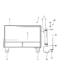
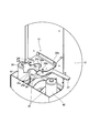
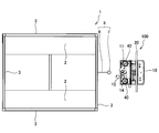
 台車1は、例えば工場などにて、重量物を運搬するのに使用される。図1に示すように、台車1は、矩形に形成される荷台2と、荷台2の外周の四辺から上方に向けて立設される立設部3と、荷台2の四つの角部を各々支持する四つの車輪4とを有するカゴ台車である。台車1は、車輪4の回転によって移動可能である。 The carriage 1 is used to carry heavy objects at a factory, for example. As shown in FIG. 1, the cart 1 includes a loading platform 2 that is formed in a rectangular shape, a standing portion 3 that is erected upward from four sides of the outer periphery of the loading platform 2, and four corners of the loading platform 2. It is a cart with four wheels 4 to support. The carriage 1 can be moved by the rotation of the wheels 4.
 台車1は、搭載された荷物を運搬可能なものであればよいため、カゴ台車に限定されない。台車1は、例えば、荷台2の一辺のみに手押しハンドルが立設される手押し台車や、作業者の操作によって荷台が昇降するハンドリフトなどであってもよい。 The cart 1 is not limited to the cart, as long as it can carry the loaded cargo. The cart 1 may be, for example, a hand cart in which a hand handle is erected only on one side of the cargo bed 2 or a hand lift in which the cargo bed is raised or lowered by an operator's operation.
 荷台2には、荷物が載置される。本実施形態では、荷台2は、左右に分割されて一対設けられる矩形の板である。荷台2は、全面に設けられる矩形の一枚板であってもよい。 Luggage is placed on the loading platform 2. In this embodiment, the loading platform 2 is a rectangular plate that is divided into left and right and provided as a pair. The loading platform 2 may be a rectangular single plate provided on the entire surface.
 車輪4は、走行時に常に進行方向を向く自在輪である。全ての車輪4を自在輪とするのではなく、例えば、アシストユニット100から離れた一対の車輪4を固定輪とし、アシストユニット100に近い一対の車輪4のみを自在輪としてもよい。このようにアシストユニットから離れた一対の車輪4を固定輪とすることで、台車1の直進性が向上する。 Wheel 4 is a free wheel that always faces the direction of travel when traveling. Instead of using all the wheels 4 as universal wheels, for example, a pair of wheels 4 that are separated from the assist unit 100 may be fixed wheels, and only a pair of wheels 4 that are close to the assist unit 100 may be universal wheels. By making the pair of wheels 4 away from the assist unit as fixed wheels in this way, the straight traveling performance of the carriage 1 is improved.
 台車1には、荷台2の一辺の立設部3に、アシストユニット100を連結するための連結部材5が取り付けられる。 A connecting member 5 for connecting the assist unit 100 is attached to the cart 1 at a standing portion 3 on one side of the loading platform 2.
 連結部材5は、立設部3に固定されるブラケット6と、ブラケット6の自由端に設けられる連結棒7とを有する。 The connecting member 5 has a bracket 6 fixed to the standing portion 3 and a connecting rod 7 provided at the free end of the bracket 6.
 ブラケット6は、立設部3に溶接される。溶接に代えて、ボルト締結によってブラケット6を取り付けてもよい。ブラケット6を立設部3にボルト締結する場合には、連結部材5を台車1に容易に取り付けることが可能である。また、ブラケット6をボルト締結できればよいため、既存の様々な形状の台車に連結部材5を取り付けて、アシストユニット100を連結することが可能である。 The bracket 6 is welded to the standing portion 3. Instead of welding, the bracket 6 may be attached by bolt fastening. When the bracket 6 is bolted to the standing portion 3, the connecting member 5 can be easily attached to the carriage 1. Further, since it is sufficient that the bracket 6 can be bolted, it is possible to connect the assist unit 100 by attaching the connecting member 5 to existing carts of various shapes.
 連結棒7は、台車1からブラケット6の長さだけ外部に突出して設けられる円筒状の棒材である。連結棒7は、地面に対して垂直に設けられる。連結棒7は、後述する上部フック機構11が係合する位置と下部フック機構12が係合する位置との間がブラケット6を介して台車1に連結される。連結棒7には、アシストユニット100が取り付けられる。連結棒7は、円筒状ではなく円形断面を有する中実丸棒であってもよい。 The connecting rod 7 is a cylindrical rod provided to protrude outward from the carriage 1 by the length of the bracket 6. The connecting rod 7 is provided perpendicular to the ground. The connecting rod 7 is connected to the carriage 1 via a bracket 6 between a position where an upper hook mechanism 11 described later is engaged and a position where the lower hook mechanism 12 is engaged. An assist unit 100 is attached to the connecting rod 7. The connecting rod 7 may be a solid round rod having a circular cross section instead of a cylindrical shape.
 次に、図5から図7を参照して、アシストユニット100について説明する。 Next, the assist unit 100 will be described with reference to FIGS.
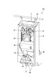
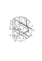
 アシストユニット100は、作業者によって台車1に付与される駆動力をアシストするものである。アシストユニット100は、台車1に対して旋回可能に連結されるユニット本体10と、作業者によって押圧操作されて、ユニット本体10を介して台車1に駆動力を入力可能な操作部としての操作ハンドル20と、ユニット本体10に前後方向にのみ回転可能に設けられ、操作ハンドル20の操作に応じたアシスト力が付与される駆動輪30とを備える。 The assist unit 100 assists the driving force applied to the carriage 1 by an operator. The assist unit 100 includes a unit main body 10 that is turnably connected to the carriage 1 and an operation handle as an operation unit that is pressed by an operator and can input a driving force to the carriage 1 through the unit main body 10. 20 and a drive wheel 30 provided on the unit main body 10 so as to be rotatable only in the front-rear direction and to which an assist force according to the operation of the operation handle 20 is applied.
 ユニット本体10は、縦長のボックス状に形成され、駆動輪30によって支持される。ユニット本体10は、連結棒7に係合する上部係合機構としての上部フック機構11及び下部係合機構としての下部フック機構12を有する。また、ユニット本体10には、アシストユニット100が台車1に連結された状態では接地しない補助輪13(図6及び図7参照)が設けられる。 The unit body 10 is formed in a vertically long box shape and is supported by the drive wheels 30. The unit body 10 includes an upper hook mechanism 11 as an upper engagement mechanism that engages with the connecting rod 7 and a lower hook mechanism 12 as a lower engagement mechanism. Further, the unit body 10 is provided with auxiliary wheels 13 (see FIGS. 6 and 7) that are not grounded when the assist unit 100 is connected to the carriage 1.
 上部フック機構11は、作業者が手動で連結棒7に係合させるものである。一方、下部フック機構12は、アシストユニット100を台車1に押し当てるだけで、ワンタッチで連結棒7に係合可能なものである。アシストユニット100は、上部フック機構11と下部フック機構12とが連結棒7を保持することによって台車1に連結される。上部フック機構11及び下部フック機構12については、後で図8から図11を参照して詳細に説明する。 The upper hook mechanism 11 is manually engaged with the connecting rod 7 by the operator. On the other hand, the lower hook mechanism 12 can be engaged with the connecting rod 7 with one touch only by pressing the assist unit 100 against the carriage 1. The assist unit 100 is connected to the carriage 1 by the upper hook mechanism 11 and the lower hook mechanism 12 holding the connecting rod 7. The upper hook mechanism 11 and the lower hook mechanism 12 will be described in detail later with reference to FIGS.
 補助輪13は、駆動輪30から前後方向に離間して設けられ、駆動輪30と同じ方向にのみ回転可能な固定輪である。補助輪13は、アシストユニット100を台車1から取り外して単体で移動させる場合に接地させて使用するものである。具体的には、作業者は、台車1から取り外したアシストユニット100を前後に傾けて補助輪13を接地させ、一対の駆動輪30と補助輪13との三輪が接地した状態でアシストユニット100を移動させることができる。よって、アシストユニット100の単体での安定した移動が可能である。 The auxiliary wheel 13 is a fixed wheel that is provided apart from the driving wheel 30 in the front-rear direction and is rotatable only in the same direction as the driving wheel 30. The auxiliary wheel 13 is used while being grounded when the assist unit 100 is detached from the carriage 1 and moved alone. Specifically, the worker tilts the assist unit 100 removed from the carriage 1 back and forth to ground the auxiliary wheel 13 and places the assist unit 100 in a state where the three wheels of the pair of driving wheels 30 and the auxiliary wheel 13 are grounded. Can be moved. Therefore, stable movement of the assist unit 100 alone is possible.
 なお、単一の駆動輪30が設けられる場合には、補助輪13は一対設けられる。これにより、一対の駆動輪30が設けられる場合と同様に、三輪が接地することで、アシストユニット100の単体での安定した移動が可能である。 When a single drive wheel 30 is provided, a pair of auxiliary wheels 13 are provided. As a result, as in the case where the pair of drive wheels 30 are provided, the three wheels are grounded, so that the assist unit 100 can be stably moved alone.
 操作ハンドル20は、ユニット本体10に設けられ、作業者によって押圧操作されるハンドルである。操作ハンドル20は、ユニット本体10の左右方向に水平に延設される棒材である。操作ハンドル20は、その左右をユニット本体10上方に連結される。これにより、作業者が操作ハンドル20を操作することによって入力される駆動力が、ユニット本体10を介して台車1に伝達される。 The operation handle 20 is a handle provided in the unit main body 10 and pressed by an operator. The operation handle 20 is a bar that extends horizontally in the left-right direction of the unit body 10. The operation handle 20 is connected to the upper side of the unit main body 10 at the left and right. Thereby, the driving force input by the operator operating the operation handle 20 is transmitted to the carriage 1 via the unit body 10.
 駆動輪30は、ユニット本体10の前後方向に向かって転舵不能に設けられる。駆動輪30は、ユニット本体10の左右に間隔をあけて一対設けられる。駆動輪30は、ユニット本体10の旋回中心を挟んで左右に並べて設けられる。本実施の形態では、駆動輪30は一対設けられるが、これに代えて、単一の駆動輪30を設けてもよい。 The driving wheel 30 is provided so as not to be steered in the front-rear direction of the unit body 10. A pair of drive wheels 30 are provided on the left and right sides of the unit body 10 with a space therebetween. The drive wheels 30 are provided side by side on both sides of the turning center of the unit body 10. In the present embodiment, a pair of drive wheels 30 are provided, but instead, a single drive wheel 30 may be provided.
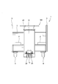
 また、図6に示すように、アシストユニット100は、操作ハンドル20から入力される駆動トルクを検出するトルク検出部としてのトルクセンサ21と、トルクセンサ21によって検出された駆動トルクに応じたアシスト力を駆動輪30に付与する電動モータ40と、トルクセンサ21によって検出された駆動トルクに応じて電動モータ40を制御するコントローラ50と、電源装置としてのバッテリ60とを備える。 As shown in FIG. 6, the assist unit 100 includes a torque sensor 21 serving as a torque detection unit that detects a drive torque input from the operation handle 20, and an assist force according to the drive torque detected by the torque sensor 21. Is provided to the driving wheel 30, a controller 50 that controls the electric motor 40 according to the driving torque detected by the torque sensor 21, and a battery 60 as a power supply device.
 トルクセンサ21とコントローラ50とバッテリ60と電動モータ40とは、ユニット本体10内に上から順に縦に並べて配置される。これにより、アシストユニット100をコンパクトな形状とすることができる。 The torque sensor 21, the controller 50, the battery 60, and the electric motor 40 are arranged in the unit main body 10 in the vertical order from the top. Thereby, the assist unit 100 can be made into a compact shape.
 トルクセンサ21は、ユニット本体10内に一対設けられて、ユニット本体10の左右二箇所の各々に入力される駆動トルクを検出する。トルクセンサ21は、コントローラ50に電気的に接続され、検出した駆動トルクに応じた電気信号をコントローラ50に出力する。 A pair of torque sensors 21 are provided in the unit main body 10 to detect driving torque input to each of the left and right portions of the unit main body 10. The torque sensor 21 is electrically connected to the controller 50 and outputs an electrical signal corresponding to the detected driving torque to the controller 50.
 トルクセンサ21は、操作ハンドル20とユニット本体10とを連結して操作ハンドル20から入力される駆動力によって捩れるとともに駆動力をユニット本体10に伝達するトーションバー(図示省略)と、トーションバーの捩れに応じた電気信号を出力するポテンショメータ(図示省略)とを備え、トーションバーの捩れに基づいて駆動トルクを検出する。トーションバーを変更することで、その他の部材を変更することなく、台車1の積載荷重などに応じて作業者による操作感覚を変更することも可能である。 The torque sensor 21 connects the operation handle 20 and the unit main body 10 and is twisted by the driving force input from the operation handle 20 and transmits the driving force to the unit main body 10. A potentiometer (not shown) that outputs an electrical signal corresponding to the torsion is provided, and a drive torque is detected based on the torsion of the torsion bar. By changing the torsion bar, it is also possible to change the operation feeling by the operator according to the loaded load of the carriage 1 without changing other members.
 電動モータ40は、コントローラ50に電気的に接続され、コントローラ50から入力される電気信号に応じて回転する。電動モータ40は、一対設けられて、各々の駆動輪30に独立してアシスト力を付与する。 The electric motor 40 is electrically connected to the controller 50 and rotates according to an electric signal input from the controller 50. A pair of the electric motors 40 is provided and applies an assist force to each drive wheel 30 independently.
 電動モータ40は、その回転軸が地面に対して垂直な方向を向くように配設される。電動モータ40は、一対の駆動輪30の各々の外側に設けられる。これにより、一対の駆動輪30の間隔を小さくすることができる。よって、駆動輪30の回転半径が小さくなるため、作業者がアシストユニット100を回転させるために必要なモーメントを小さくすることができる。したがって、作業者によるアシストユニット100の取り回しが容易となる。 The electric motor 40 is disposed such that its rotation axis is oriented in a direction perpendicular to the ground. The electric motor 40 is provided outside each of the pair of drive wheels 30. Thereby, the space | interval of a pair of drive wheel 30 can be made small. Therefore, since the rotation radius of the drive wheel 30 is reduced, the moment required for the operator to rotate the assist unit 100 can be reduced. Therefore, handling of the assist unit 100 by an operator becomes easy.
 駆動輪30と電動モータ40との間には、電動モータ40の回転を減速するとともに回転方向を変換して駆動輪30に伝達する変速機としてのウォーム変速機41が設けられる。 Between the driving wheel 30 and the electric motor 40, there is provided a worm transmission 41 as a transmission that decelerates the rotation of the electric motor 40 and converts the rotation direction to transmit to the driving wheel 30.
 コントローラ50は、ユニット本体10に搭載される。コントローラ50は、アシストユニット100の制御を行うものであり、CPU(中央演算処理装置)、ROM(リードオンリメモリ)、RAM(ランダムアクセスメモリ)、及びI/Oインターフェース(入出力インターフェース)を備えたマイクロコンピュータで構成される。RAMはCPUの処理におけるデータを記憶し、ROMはCPUの制御プログラム等を予め記憶し、I/Oインターフェースは接続された機器との情報の入出力に使用される。CPUやRAMなどをROMに格納されたプログラムに従って動作させることによってアシストユニット100の制御が実現される。 The controller 50 is mounted on the unit main body 10. The controller 50 controls the assist unit 100 and includes a CPU (Central Processing Unit), a ROM (Read Only Memory), a RAM (Random Access Memory), and an I / O interface (input / output interface). Consists of a microcomputer. The RAM stores data in the processing of the CPU, the ROM stores a control program of the CPU in advance, and the I / O interface is used for input / output of information with the connected device. Control of the assist unit 100 is realized by operating a CPU, a RAM, and the like according to a program stored in the ROM.
 コントローラ50は、左右のトルクセンサ21によって検出された各々の駆動トルクに応じて左右各々の電動モータ40を制御し、左右の駆動輪30にアシスト力を付与する。具体的には、コントローラ50は、左側のトルクセンサ21によって検出された駆動トルクに応じて左側の電動モータ40を制御し、右側のトルクセンサ21によって検出された駆動トルクに応じて右側の電動モータ40を制御する。これにより、アシストユニット100を前進または後退させるとともに、直進、旋回、曲折させるアシスト力が付与される。 The controller 50 controls the left and right electric motors 40 according to the respective drive torques detected by the left and right torque sensors 21 and applies assist force to the left and right drive wheels 30. Specifically, the controller 50 controls the left electric motor 40 according to the driving torque detected by the left torque sensor 21, and the right electric motor according to the driving torque detected by the right torque sensor 21. 40 is controlled. As a result, an assist force for moving the assist unit 100 forward or backward as well as going straight, turning, or bending is applied.
 バッテリ60は、ユニット本体10に搭載される。バッテリ60は、コントローラ50を駆動し、コントローラ50による制御に基づいて電動モータ40に直流電源を供給する電池である。 The battery 60 is mounted on the unit main body 10. The battery 60 is a battery that drives the controller 50 and supplies DC power to the electric motor 40 based on control by the controller 50.
 次に、図8から図11を参照して、上部フック機構11及び下部フック機構12について説明する。 Next, the upper hook mechanism 11 and the lower hook mechanism 12 will be described with reference to FIGS.
 上部フック機構11は、下部フック機構12の上方に設けられる。上部フック機構11は、連結棒7に対して軸方向に摺動可能に係合する。上部フック機構11は、作業者によって係止部材としてのピン16が嵌められることによって連結棒7を介して台車1に係合可能である。 The upper hook mechanism 11 is provided above the lower hook mechanism 12. The upper hook mechanism 11 engages with the connecting rod 7 so as to be slidable in the axial direction. The upper hook mechanism 11 can be engaged with the carriage 1 via the connecting rod 7 when a pin 16 as a locking member is fitted by an operator.
 上部フック機構11は、図8に示すように、ユニット本体10に固定され連結棒7の側面が当接する固定部14と、固定部14に対して回動自在に設けられ、連結棒7を固定部14との間で挟持した状態でピン16が嵌められることによって固定部14に固定される可動部15と、作業者によって嵌められるピン16とを有する。 As shown in FIG. 8, the upper hook mechanism 11 is fixed to the unit main body 10 and fixed to the side face of the connecting rod 7, and is provided to be rotatable with respect to the fixing portion 14. It has the movable part 15 fixed to the fixing | fixed part 14 when the pin 16 is fitted in the state clamped between the parts 14, and the pin 16 fitted by an operator.
 固定部14は、基端14aがユニット本体10に取り付けられ、ユニット本体10から突出して設けられるプレートである。固定部14は、上下に平行に並べて一対設けられる。固定部14の自由端14bには、連結棒7の外形に対応する形状に形成される円弧部14dを有する凹部14cが形成される。 The fixing portion 14 is a plate provided with a base end 14 a attached to the unit main body 10 and protruding from the unit main body 10. A pair of fixing portions 14 are provided in parallel in the vertical direction. A concave portion 14 c having an arc portion 14 d formed in a shape corresponding to the outer shape of the connecting rod 7 is formed at the free end 14 b of the fixed portion 14.
 固定部14は、凹部14cの一端に形成され可動部15が回動自在に取り付けられる貫通孔14eと、凹部14cの他端に形成され可動部15が固定部14との間で連結棒7を挟持した状態でピン16を挿通可能な貫通孔14fとを有する。 The fixed portion 14 is formed at one end of the concave portion 14c and the through hole 14e to which the movable portion 15 is rotatably attached. It has a through hole 14f into which the pin 16 can be inserted while being held.
 可動部15は、固定部14の貫通孔14eに基端15aが回動自在に取り付けられるプレートである。可動部15は、一対の固定部14の間に位置する。可動部15には、固定部14との間で連結棒7を挟持した状態で固定部14の凹部14cと対向するように形成され、連結棒7の外形に対応する形状に形成される円弧部15dを有する凹部15cが形成される。 The movable part 15 is a plate whose base end 15a is rotatably attached to the through hole 14e of the fixed part 14. The movable portion 15 is located between the pair of fixed portions 14. The movable portion 15 is formed so as to face the concave portion 14c of the fixed portion 14 in a state where the connecting rod 7 is sandwiched between the movable portion 15 and an arc portion formed in a shape corresponding to the outer shape of the connecting rod 7. A recess 15c having 15d is formed.
 可動部15の自由端15bには、固定部14との間で連結棒7を挟持した状態で固定部14の貫通孔14eと同軸となる貫通孔15fが形成される。 In the free end 15b of the movable portion 15, a through hole 15f that is coaxial with the through hole 14e of the fixed portion 14 is formed in a state where the connecting rod 7 is sandwiched between the movable portion 15 and the fixed portion 14.
 ピン16は、貫通孔14f及び貫通孔15fに挿通する軸部16aと、軸部16aと比較して大径に形成される頭部16bとを有する。軸部16aは、貫通孔14f及び貫通孔15fと比較して小径に形成され、頭部16bは、貫通孔14f及び貫通孔15fと比較して大径に形成される。 The pin 16 has a shaft portion 16a that is inserted into the through hole 14f and the through hole 15f, and a head portion 16b that has a larger diameter than the shaft portion 16a. The shaft portion 16a is formed with a small diameter compared with the through hole 14f and the through hole 15f, and the head portion 16b is formed with a large diameter compared with the through hole 14f and the through hole 15f.
 ピン16は、図9に示すように、固定部14と可動部15との間で連結棒7を挟持した状態で、貫通孔14f及び貫通孔15fとの上方から軸部16aが挿通される。これにより、可動部15が固定部14に対して回動不能に固定される。ピン16は、頭部16bが上側の固定部14と当接することで、軸方向の位置が規定される。 As shown in FIG. 9, the shaft 16 a is inserted through the pin 16 from above the through hole 14 f and the through hole 15 f in a state where the connecting rod 7 is sandwiched between the fixed part 14 and the movable part 15. Thereby, the movable part 15 is fixed to the fixed part 14 so as not to rotate. The pin 16 has an axial position defined by the head portion 16b coming into contact with the upper fixing portion 14.
 一方、ピン16が貫通孔14f及び貫通孔15fから上方に引き抜かれると、図8に示すように、可動部15が固定部14に対して回動可能となる。 On the other hand, when the pin 16 is pulled upward from the through hole 14f and the through hole 15f, the movable portion 15 can rotate with respect to the fixed portion 14, as shown in FIG.
 下部フック機構12は、上部フック機構11の下方に設けられる。下部フック機構12は、連結棒7に対して軸方向に摺動可能に係合する。下部フック機構12は、ユニット本体10を台車1に押し当てることによって連結棒7を介して台車1に係合可能である。 The lower hook mechanism 12 is provided below the upper hook mechanism 11. The lower hook mechanism 12 engages with the connecting rod 7 so as to be slidable in the axial direction. The lower hook mechanism 12 can be engaged with the carriage 1 via the connecting rod 7 by pressing the unit body 10 against the carriage 1.
 下部フック機構12は、図10に示すように、ユニット本体10に固定され連結棒7が進入する凹部24cを有する固定部24と、固定部24の自由端24bにおける凹部24cの一端に対して回動自在に設けられる第一可動部25と、固定部24の自由端24bにおける凹部24cの他端に対して回動自在に設けられる第二可動部26と、ユニット本体10から外側に突出して設けられ作業者によって操作される解除レバー27とを有する。 As shown in FIG. 10, the lower hook mechanism 12 is fixed to the unit main body 10 and has a fixing portion 24 having a concave portion 24 c into which the connecting rod 7 enters, and the lower hook mechanism 12 rotates with respect to one end of the concave portion 24 c at the free end 24 b of the fixing portion 24. A first movable part 25 provided movably, a second movable part 26 provided rotatably with respect to the other end of the recess 24 c at the free end 24 b of the fixed part 24, and provided projecting outward from the unit body 10. And a release lever 27 operated by an operator.
 固定部24は、基端24aがユニット本体10に取り付けられ、ユニット本体10から突出して設けられるプレートである。固定部24は、上下に平行に並べて一対設けられる。固定部24の自由端24bには、連結棒7の外形に対応する形状に形成される円弧部24dを有する凹部24cが形成される。 The fixing portion 24 is a plate provided with a base end 24 a attached to the unit body 10 and protruding from the unit body 10. A pair of fixing portions 24 are provided in parallel in the vertical direction. A concave portion 24 c having an arc portion 24 d formed in a shape corresponding to the outer shape of the connecting rod 7 is formed at the free end 24 b of the fixed portion 24.
 固定部24は、凹部24cの一端に形成され第一可動部25が回動自在に取り付けられる貫通孔24fと、凹部24cの他端に形成され第二可動部26が回動自在に取り付けられる貫通孔24eとを有する。 The fixed portion 24 is formed at one end of the recess 24c and the through hole 24f to which the first movable portion 25 is rotatably attached, and the through hole formed at the other end of the recess 24c and to which the second movable portion 26 is rotatably attached. And a hole 24e.
 第一可動部25は、固定部24の貫通孔24fに回動自在に取り付けられるプレートである。第一可動部25は、一対の固定部24の間に位置する。第一可動部25は、連結棒7が凹部24cに進入する際に連結棒7に押されて凹部24cを閉塞して連結棒7を挟持するように回動する。 The first movable portion 25 is a plate that is rotatably attached to the through hole 24f of the fixed portion 24. The first movable part 25 is located between the pair of fixed parts 24. The first movable portion 25 rotates so that the connecting rod 7 is pushed by the connecting rod 7 when the connecting rod 7 enters the concave portion 24 c to close the concave portion 24 c and sandwich the connecting rod 7.
 第一可動部25には、連結棒7の外形に対応する形状に形成される円弧部25dを有し、連結棒7が凹部24cに進入する際に連結棒7と摺接する凹部25cと、第二可動部26と係合する係合部25aとが形成される。 The first movable portion 25 has an arc portion 25d formed in a shape corresponding to the outer shape of the connecting rod 7, and a concave portion 25c that comes into sliding contact with the connecting rod 7 when the connecting rod 7 enters the concave portion 24c; An engaging portion 25 a that engages with the two movable portions 26 is formed.
 第一可動部25は、連結棒7が凹部24cに進入する際には、凹部25cに連結棒7が当接した状態で、連結棒7によって押されて回動する。これにより、凹部25cが凹部24cと同軸上に位置して、連結棒7は、固定部24と第一可動部25とによって挟持されることとなる。 When the connecting rod 7 enters the recess 24c, the first movable portion 25 is pushed by the connecting rod 7 and rotates with the connecting rod 7 in contact with the recess 25c. Thereby, the recessed part 25c is located on the same axis as the recessed part 24c, and the connecting rod 7 is sandwiched between the fixed part 24 and the first movable part 25.
 係合部25aは、第一可動部25が回動する際には、第二可動部26の挟持部26cに摺接する。係合部25aは、第一可動部25が回動して凹部25cが凹部24cと同軸上に位置した状態では、第二可動部26の係合突起部26aによって係止される。これにより、第一可動部25が回動不能に固定される。 The engaging portion 25a is in sliding contact with the clamping portion 26c of the second movable portion 26 when the first movable portion 25 rotates. The engaging portion 25a is locked by the engaging protrusion 26a of the second movable portion 26 in a state where the first movable portion 25 rotates and the concave portion 25c is positioned coaxially with the concave portion 24c. Thereby, the 1st movable part 25 is fixed so that rotation is impossible.
 第二可動部26は、固定部24の貫通孔24eに回動自在に取り付けられるプレートである。第二可動部26は、一対の固定部24の間に位置する。第二可動部26は、連結棒7を挟持した状態で第一可動部25に係合して固定する係合突起部26aと、連結棒7を凹部25cとの間で挟持する挟持部26cとを有する。 The second movable portion 26 is a plate that is rotatably attached to the through hole 24e of the fixed portion 24. The second movable part 26 is located between the pair of fixed parts 24. The second movable portion 26 includes an engaging protrusion 26a that engages and fixes the first movable portion 25 in a state where the connecting rod 7 is held, and a holding portion 26c that holds the connecting rod 7 between the recessed portion 25c. Have
 係合突起部26aは、連結棒7が凹部24cに進入する際には、第一可動部25の係合部25aによって押される。そして、第二可動部26が回動すると、第一可動部25の係合部25aが係合突起部26aを乗り越えることとなる。これにより、係合突起部26aは、係合部25aを係止して第一可動部25を固定する(図11に示す状態)。 The engaging protrusion 26a is pushed by the engaging portion 25a of the first movable portion 25 when the connecting rod 7 enters the recess 24c. And if the 2nd movable part 26 rotates, the engaging part 25a of the 1st movable part 25 will get over the engaging protrusion part 26a. Thereby, the engaging protrusion part 26a locks the engaging part 25a, and fixes the 1st movable part 25 (state shown in FIG. 11).
 解除レバー27は、第二可動部26と一体に設けられる。解除レバー27は、下部フック機構12の連結棒7への係合を解除する際に、作業者によって操作される。 The release lever 27 is provided integrally with the second movable portion 26. The release lever 27 is operated by an operator when releasing the engagement of the lower hook mechanism 12 with the connecting rod 7.
 作業者によって解除レバー27がユニット本体10から離間する方向に操作されると、第二可動部26が解除レバー27と一体に回動して、係合突起部26aと係合部25aとの係合が解除される。これにより、第一可動部25の固定は解除されて回動可能となり、連結棒7を固定部24の凹部24cから離間させることが可能となる。 When the release lever 27 is operated in a direction away from the unit body 10 by the operator, the second movable portion 26 rotates integrally with the release lever 27, and the engagement protrusion 26a and the engagement portion 25a are engaged. The match is released. As a result, the fixing of the first movable portion 25 is released and the first movable portion 25 can be rotated, and the connecting rod 7 can be separated from the concave portion 24 c of the fixing portion 24.
 次に、図1から図4を参照して、アシストユニット100の作用について説明する。 Next, the operation of the assist unit 100 will be described with reference to FIGS.
 まず、アシストユニット100を介して台車1を真っ直ぐ前進又は後退させる場合について説明する。ここでは、アシストユニット100が台車1を押す場合を前進といい、台車1を牽引する場合を後退という。 First, the case where the cart 1 is moved forward or backward straight through the assist unit 100 will be described. Here, the case where the assist unit 100 pushes the carriage 1 is called forward, and the case where the carriage 1 is pulled is called backward.
 作業者が操作ハンドル20を両手で平行に押した場合には、アシストユニット100は、台車1を真っ直ぐ前進させることとなる。この場合、操作ハンドル20が押されることによってユニット本体10に入力される駆動力は操作ハンドル20の左右両端で略同一である。よって、左右のトルクセンサ21によって検出される駆動トルクは、略同一となる。 When the operator pushes the operation handle 20 in parallel with both hands, the assist unit 100 moves the carriage 1 straight forward. In this case, the driving force input to the unit main body 10 when the operation handle 20 is pressed is substantially the same at the left and right ends of the operation handle 20. Therefore, the drive torque detected by the left and right torque sensors 21 is substantially the same.
 左右のトルクセンサ21が同一の駆動トルクを検出すると、コントローラ50は、左右の電動モータ40から左右の駆動輪30に同一のアシスト力を付与するように指令する。これにより、左右の駆動輪30には、同一のアシスト力が付与される。 When the left and right torque sensors 21 detect the same drive torque, the controller 50 commands the left and right electric motors 40 to apply the same assist force to the left and right drive wheels 30. Thereby, the same assist force is applied to the left and right drive wheels 30.
 したがって、アシストユニット100は、台車1に対して旋回せずに同じ方向を向いたまま、作業者によって付与される駆動力に電動モータ40のアシスト力が付与されて台車1を真っ直ぐ前進させることができる。 Therefore, the assist unit 100 can move the cart 1 straight forward by applying the assist force of the electric motor 40 to the driving force applied by the operator while turning in the same direction without turning with respect to the cart 1. it can.
 なお、台車1を真っ直ぐ後退させる場合には、操作ハンドル20が押される方向が逆になり、電動モータ40の回転方向が逆になるだけで、その他の作用は真っ直ぐ前進する場合と同様である。 It should be noted that when the carriage 1 is moved straight back, the direction in which the operation handle 20 is pushed is reversed, and the rotation direction of the electric motor 40 is reversed, and the other actions are the same as in the case of moving straight forward.
 次に、アシストユニット100を介して台車1を旋回走行させる場合について説明する。 Next, the case where the cart 1 is turned through the assist unit 100 will be described.
 作業者が操作ハンドル20を押す左右の力を相違させた場合には、アシストユニット100は、左又は右に旋回走行することとなる。このとき、左右の駆動輪30に付与されるアシスト力は、左右の電動モータ40で相違する。 If the left and right forces pushing the operation handle 20 are different, the assist unit 100 turns left or right. At this time, the assist force applied to the left and right drive wheels 30 differs between the left and right electric motors 40.
 具体的には、例えば台車1を左方向に旋回させる場合、作業者が右手で操作ハンドル20を押す力は、左手で操作ハンドル20を押す力と比較して大きくなる。よって、右側のトルクセンサ21が検出する駆動トルクは、左側のトルクセンサ21が検出する駆動トルクと比較して大きくなる。 Specifically, for example, when the carriage 1 is turned leftward, the force with which the operator pushes the operation handle 20 with the right hand is larger than the force with which the operation handle 20 is pushed with the left hand. Therefore, the drive torque detected by the right torque sensor 21 is larger than the drive torque detected by the left torque sensor 21.
 コントローラ50は、右側の電動モータ40から駆動輪30に付与するアシスト力が、左側の電動モータ40から駆動輪30に付与するアシスト力と比較して大きくなるように指令する。これにより、右側の駆動輪30に付与されるアシスト力は、左側の駆動輪30に付与されるアシスト力と比較して大きくなる。 The controller 50 commands the assist force applied from the right electric motor 40 to the drive wheels 30 to be larger than the assist force applied from the left electric motor 40 to the drive wheels 30. As a result, the assist force applied to the right drive wheel 30 is greater than the assist force applied to the left drive wheel 30.
 よって、アシストユニット100は、台車1に対して旋回した状態となる。このように、アシストユニット100は、台車1を前進又は後退させるアシスト力だけでなく、台車1を旋回させるためのモーメントも付与することができる。したがって、アシストユニット100は、作業者によって付与される駆動力に電動モータ40のアシスト力が付与されて台車1を旋回走行させることができる。 Therefore, the assist unit 100 is turned with respect to the carriage 1. Thus, the assist unit 100 can give not only an assist force for moving the carriage 1 forward or backward, but also a moment for turning the carriage 1. Therefore, the assist unit 100 can turn the carriage 1 by applying the assist force of the electric motor 40 to the drive force applied by the operator.
 ユニット本体10は台車1に対して旋回可能に連結されている。また、駆動輪30は、ユニット本体10に前後方向にのみ回転可能に設けられている。よって、駆動輪30は、ユニット本体10に対して旋回しないため、駆動輪30を旋回させる機構が不要である。したがって、台車1のアシストユニット100の構造を簡素化することができる。 The unit body 10 is connected to the carriage 1 so as to be turnable. The drive wheels 30 are provided in the unit body 10 so as to be rotatable only in the front-rear direction. Therefore, since the drive wheel 30 does not turn with respect to the unit body 10, a mechanism for turning the drive wheel 30 is unnecessary. Therefore, the structure of the assist unit 100 of the cart 1 can be simplified.
 また、台車1に重量物が搭載された場合には、作業者の操作に基づいてアシストユニット100からアシスト力を付与して台車1を移動させることができる。一方、台車1に搭載された荷物が軽い場合や空荷の場合には、アシストユニット100からアシスト力を付与することなく作業者による駆動力のみで台車1を移動させることができる。 Further, when a heavy object is mounted on the cart 1, the cart 1 can be moved by applying an assist force from the assist unit 100 based on the operation of the operator. On the other hand, when the load mounted on the cart 1 is light or empty, the cart 1 can be moved only by the driving force of the operator without applying the assist force from the assist unit 100.
 なお、左右のトルクセンサ21は、駆動トルクを無段階に検出可能であるため、作業者が操作ハンドル20を押圧操作する力に応じてアシスト力の大きさをコントロールすることができる。 Since the left and right torque sensors 21 can detect the drive torque steplessly, the magnitude of the assist force can be controlled according to the force with which the operator presses the operation handle 20.
 次に、主に図12及び図13を参照して、アシストユニット100の台車1への連結及び取り外しについて説明する。 Next, the connection and removal of the assist unit 100 from the carriage 1 will be described mainly with reference to FIGS.
 アシストユニット100を台車1に連結する際には、作業者は、下部フック機構12を連結棒7に押し当てるように、アシストユニット100を台車1に向けて移動させる。このとき、上部フック機構11の可動部15は、固定部14の凹部14cに連結棒7が進入可能なように開かれている。 When connecting the assist unit 100 to the carriage 1, the operator moves the assist unit 100 toward the carriage 1 so as to press the lower hook mechanism 12 against the connecting rod 7. At this time, the movable portion 15 of the upper hook mechanism 11 is opened so that the connecting rod 7 can enter the concave portion 14 c of the fixed portion 14.
 作業者が、下部フック機構12に連結棒7が進入するようにアシストユニット100のユニット本体10を押し当てると、第一可動部25の凹部25cと固定部24の凹部24cとが同軸上に位置するまで第一可動部25が回動する。このとき、第一可動部25の係合部25aは、第二可動部26の挟持部26cに摺接する。 When the operator presses the unit main body 10 of the assist unit 100 so that the connecting rod 7 enters the lower hook mechanism 12, the concave portion 25c of the first movable portion 25 and the concave portion 24c of the fixed portion 24 are positioned coaxially. The first movable part 25 rotates until it is done. At this time, the engaging portion 25 a of the first movable portion 25 is in sliding contact with the clamping portion 26 c of the second movable portion 26.
 そして、係合部25aが係合突起部26aを乗り越えた後、第一可動部25の凹部25cと固定部24の凹部24cとが同軸上となる。これにより、第一可動部25は、係合部25aが係合突起部26aに係止されることによって、固定部24に回動不能に固定されることとなる。 And after the engaging part 25a gets over the engaging protrusion part 26a, the recessed part 25c of the 1st movable part 25 and the recessed part 24c of the fixing | fixed part 24 become coaxial. Thereby, the first movable part 25 is fixed to the fixing part 24 so as not to be rotatable by the engaging part 25a being locked to the engaging protrusion part 26a.
 このように、下部フック機構12は、アシストユニット100のユニット本体10を台車1に押し当てるだけで、ワンタッチで連結棒7に係合可能である。したがって、アシストユニット100と台車1との連結を容易にすることができる。 As described above, the lower hook mechanism 12 can be engaged with the connecting rod 7 with one touch only by pressing the unit main body 10 of the assist unit 100 against the carriage 1. Therefore, the assist unit 100 and the carriage 1 can be easily connected.
 作業者は、下部フック機構12が連結棒7に係合した後、上部フック機構11の可動部15を回動させて、可動部15と固定部14との間で連結棒7を挟持する。そして、同軸上に位置する貫通孔14fと貫通孔15fとに、上方からピン16を挿入する。これにより、可動部15は、固定部14に回動不能に固定され、上部フック機構11が連結棒7に係合することとなる。 After the lower hook mechanism 12 is engaged with the connecting rod 7, the operator rotates the movable portion 15 of the upper hook mechanism 11 to sandwich the connecting rod 7 between the movable portion 15 and the fixed portion 14. Then, the pin 16 is inserted into the through hole 14f and the through hole 15f located on the same axis from above. Thereby, the movable part 15 is fixed to the fixed part 14 so as not to rotate, and the upper hook mechanism 11 is engaged with the connecting rod 7.
 上部フック機構11は、下部フック機構12の上方に設けられ、比較的高い位置に位置するため、作業者によるピン16を嵌める操作が容易である。したがって、アシストユニット100と台車1との連結を容易にすることができる。 The upper hook mechanism 11 is provided above the lower hook mechanism 12 and is located at a relatively high position, so that the operator can easily fit the pin 16. Therefore, the assist unit 100 and the cart 1 can be easily connected.
 また、例えば、下部フック機構12の解除レバー27が外部の障害物との接触によって作業者の意に反して操作され、下部フック機構12の連結棒7への係合が解除されたような場合であっても、上部フック機構11の連結棒7への係合は維持される。このように、上部フック機構11と下部フック機構12とを異なる構造としたため、アシストユニット100の台車1への連結を確実に行うことができる。 Further, for example, when the release lever 27 of the lower hook mechanism 12 is operated against the operator's will by contact with an external obstacle, and the engagement of the lower hook mechanism 12 with the connecting rod 7 is released. Even so, the engagement of the upper hook mechanism 11 with the connecting rod 7 is maintained. Thus, since the upper hook mechanism 11 and the lower hook mechanism 12 have different structures, the assist unit 100 can be reliably connected to the carriage 1.
 一方、アシストユニット100を台車1から取り外す際には、作業者は、上部フック機構11のピン16を、貫通孔14f及び貫通孔15fから上方に引き抜く。これにより、可動部15は、固定部14に対して回動可能となる。よって、上部フック機構11の連結棒7への係合が解除される。 On the other hand, when removing the assist unit 100 from the carriage 1, the operator pulls the pin 16 of the upper hook mechanism 11 upward from the through hole 14f and the through hole 15f. Thereby, the movable part 15 can be rotated with respect to the fixed part 14. Accordingly, the engagement of the upper hook mechanism 11 with the connecting rod 7 is released.
 この場合もまた、上部フック機構11は、下部フック機構12の上方に設けられ、比較的高い位置に位置するため、作業者によるピン16を引き抜く操作が容易である。したがって、アシストユニット100の台車1からの取り外しを容易にすることができる。 Also in this case, the upper hook mechanism 11 is provided above the lower hook mechanism 12 and is located at a relatively high position, so that the operator can easily pull out the pin 16. Therefore, the assist unit 100 can be easily detached from the carriage 1.
 作業者は、上部フック機構11の連結棒7への係合が解除された後、下部フック機構12の解除レバー27をユニット本体10から離間する方向に操作する。すると、第二可動部26が解除レバー27と一体に回動して、係合突起部26aと係合部25aとの係合が解除される。これにより、第一可動部25の固定は解除されて回動可能となり、連結棒7を固定部24の凹部24cから離間させることが可能となる。よって、下部フック機構12の連結棒7への係合が解除される。 The operator operates the release lever 27 of the lower hook mechanism 12 in the direction away from the unit body 10 after the engagement of the upper hook mechanism 11 with the connecting rod 7 is released. Then, the 2nd movable part 26 rotates integrally with the cancellation | release lever 27, and engagement with the engagement protrusion part 26a and the engagement part 25a is cancelled | released. As a result, the fixing of the first movable portion 25 is released and the first movable portion 25 can be rotated, and the connecting rod 7 can be separated from the concave portion 24 c of the fixing portion 24. Therefore, the engagement of the lower hook mechanism 12 with the connecting rod 7 is released.
 このように、下部フック機構12は、作業者が解除レバー27を操作するだけで、連結棒7への係合が解除される。したがって、アシストユニット100の台車1からの取り外しを容易にすることができる。 Thus, the lower hook mechanism 12 is released from engagement with the connecting rod 7 only by the operator operating the release lever 27. Therefore, the assist unit 100 can be easily detached from the carriage 1.
 以上の実施の形態によれば、以下に示す効果を奏する。 According to the above embodiment, the following effects are obtained.
 アシストユニット100のユニット本体10を台車1に押し当てると、下部フック機構12が連結棒7を介して台車1に係合する。そして、作業者によって上部フック機構11のピン16が嵌められると、上部フック機構11が連結棒7を介して台車1に係合する。上部フック機構11は、下部フック機構12の上方に設けられ、比較的高い位置に位置する。そのため、作業者によるピン16を嵌める操作が容易である。したがって、アシストユニット100と台車1との連結を容易にすることができる。 When the unit body 10 of the assist unit 100 is pressed against the carriage 1, the lower hook mechanism 12 is engaged with the carriage 1 via the connecting rod 7. Then, when the pin 16 of the upper hook mechanism 11 is fitted by the operator, the upper hook mechanism 11 is engaged with the carriage 1 via the connecting rod 7. The upper hook mechanism 11 is provided above the lower hook mechanism 12 and is located at a relatively high position. Therefore, the operation for fitting the pin 16 by the operator is easy. Therefore, the assist unit 100 and the carriage 1 can be easily connected.
 また、例えば、下部フック機構12の解除レバー27が外部の障害物との接触によって作業者の意に反して操作され、下部フック機構12の連結棒7への係合が解除されたような場合であっても、上部フック機構11の連結棒7への係合は維持される。このように、上部フック機構11と下部フック機構12とを異なる構造としたため、アシストユニット100の台車1への連結を確実に行うことができる。 Further, for example, when the release lever 27 of the lower hook mechanism 12 is operated against the operator's will by contact with an external obstacle, and the engagement of the lower hook mechanism 12 with the connecting rod 7 is released. Even so, the engagement of the upper hook mechanism 11 with the connecting rod 7 is maintained. Thus, since the upper hook mechanism 11 and the lower hook mechanism 12 have different structures, the assist unit 100 can be reliably connected to the carriage 1.
 以上、本発明の実施形態について説明したが、上記実施形態は本発明の適用例の一部を示したに過ぎず、本発明の技術的範囲を上記実施形態の具体的構成に限定する趣旨ではない。 The embodiment of the present invention has been described above. However, the above embodiment only shows a part of application examples of the present invention, and the technical scope of the present invention is limited to the specific configuration of the above embodiment. Absent.
 本願は2013年3月26日に日本国特許庁に出願された特願2013-064460に基づく優先権を主張し、この出願の全ての内容は参照により本明細書に組み込まれる。
 
This application claims priority based on Japanese Patent Application No. 2013-064460 filed with the Japan Patent Office on March 26, 2013, the entire contents of which are hereby incorporated by reference.

Claims (5)

  1.  作業者によって台車に付与される駆動力をアシストする台車の駆動アシストユニットであって、
     前記台車に対して旋回可能に連結されるユニット本体と、
     前記ユニット本体に設けられ、作業者によって押圧操作されて、前記ユニット本体を介して前記台車に駆動力を入力可能な操作部と、
     前記ユニット本体の前後方向に回転可能に設けられ、前記操作部の操作に応じたアシスト力が付与される駆動輪と、
     前記ユニット本体を前記台車に押し当てることによって前記台車に係合可能な下部係合機構と、
     前記下部係合機構の上方に設けられ、作業者によって係止部材が嵌められることによって前記台車に係合可能な上部係合機構と、を備える台車の駆動アシストユニット。
    A cart drive assist unit that assists a driving force applied to the cart by an operator,
    A unit body that is pivotably coupled to the carriage;
    An operation unit that is provided in the unit main body and is pressed by an operator and capable of inputting a driving force to the carriage via the unit main body;
    A drive wheel provided rotatably in the front-rear direction of the unit main body, and provided with an assist force according to the operation of the operation unit;
    A lower engagement mechanism that is engageable with the carriage by pressing the unit body against the carriage;
    A cart drive assist unit comprising: an upper engagement mechanism that is provided above the lower engagement mechanism and is engageable with the cart when a locking member is fitted by an operator.
  2.  請求項1に記載の台車の駆動アシストユニットであって、
     前記台車には、地面に対して垂直な連結棒が外部に突出するように取り付けられ、
     前記上部係合機構及び前記下部係合機構は、前記連結棒を介して前記台車に係合する台車の駆動アシストユニット。
    A drive assist unit for a carriage according to claim 1,
    A connecting rod perpendicular to the ground is attached to the carriage so that it protrudes to the outside,
    The upper engagement mechanism and the lower engagement mechanism are cart drive assist units that engage the cart via the connecting rod.
  3.  請求項2に記載の台車の駆動アシストユニットであって、
     前記上部係合機構は、
     前記ユニット本体に固定され、前記連結棒の側面に当接する固定部と、
     前記固定部に対して回動自在に設けられ、前記連結棒を前記固定部との間で挟持した状態で前記係止部材が嵌められることによって前記固定部に固定される可動部と、を有する台車の駆動アシストユニット。
    A cart drive assist unit according to claim 2,
    The upper engagement mechanism is
    A fixing portion fixed to the unit main body and abutting against a side surface of the connecting rod;
    A movable portion that is provided so as to be rotatable with respect to the fixed portion, and is fixed to the fixed portion by fitting the locking member in a state where the connecting rod is sandwiched between the fixed portion and the fixed portion. Dolly drive assist unit.
  4.  請求項2に記載の台車の駆動アシストユニットであって、
     前記下部係合機構は、
     前記ユニット本体に固定され、前記連結棒が進入する凹部を有する固定部と、
     前記固定部の前記凹部の一端に対して回動自在に設けられ、前記連結棒が前記凹部に進入する際に前記連結棒に押されて前記凹部を閉塞して前記連結棒を挟持するように回動する第一可動部と、
     前記固定部における前記凹部の他端に対して回動自在に設けられ、前記連結棒を挟持した状態で前記第一可動部に係合して固定する第二可動部と、を有する台車の駆動アシストユニット。
    A cart drive assist unit according to claim 2,
    The lower engagement mechanism is
    A fixed portion fixed to the unit body and having a recess into which the connecting rod enters;
    Provided so as to be rotatable with respect to one end of the concave portion of the fixed portion, and when the connecting rod enters the concave portion, the connecting rod is pushed by the connecting rod to close the concave portion and sandwich the connecting rod. A rotating first movable part;
    A dolly drive having a second movable portion that is rotatably provided with respect to the other end of the concave portion in the fixed portion and that engages and fixes the first movable portion in a state where the connecting rod is sandwiched. Assist unit.
  5.  請求項4に記載の台車の駆動アシストユニットであって、
     前記下部係合機構は、前記ユニット本体から外側に突出して設けられ作業者によって操作されると前記第二可動部と一体に回動して前記第一可動部の固定を解除可能な解除レバーを更に有する台車の駆動アシストユニット。
     
    A drive assist unit for a carriage according to claim 4,
    The lower engagement mechanism is provided with a release lever that protrudes outward from the unit main body and rotates integrally with the second movable part when operated by an operator to release the first movable part. Furthermore, the cart has a drive assist unit.
PCT/JP2014/058464 2013-03-26 2014-03-26 Drive-assist unit for bogies WO2014157308A1 (en)

Priority Applications (2)

Application Number Priority Date Filing Date Title
US14/779,327 US9849900B2 (en) 2013-03-26 2014-03-26 Driving assist unit of truck
CN201480016418.XA CN105189250B (en) 2013-03-26 2014-03-26 The driving auxiliary unit of chassis

Applications Claiming Priority (2)

Application Number Priority Date Filing Date Title
JP2013-064460 2013-03-26
JP2013064460A JP5998091B2 (en) 2013-03-26 2013-03-26 Dolly drive assist unit

Publications (1)

Publication Number Publication Date
WO2014157308A1 true WO2014157308A1 (en) 2014-10-02

Family

ID=51624271

Family Applications (1)

Application Number Title Priority Date Filing Date
PCT/JP2014/058464 WO2014157308A1 (en) 2013-03-26 2014-03-26 Drive-assist unit for bogies

Country Status (4)

Country Link
US (1) US9849900B2 (en)
JP (1) JP5998091B2 (en)
CN (1) CN105189250B (en)
WO (1) WO2014157308A1 (en)

Cited By (1)

* Cited by examiner, † Cited by third party
Publication number Priority date Publication date Assignee Title
CN107635849A (en) * 2015-09-11 2018-01-26 康贝株式会社 Perambulator

Families Citing this family (4)

* Cited by examiner, † Cited by third party
Publication number Priority date Publication date Assignee Title
JP2016117420A (en) * 2014-12-22 2016-06-30 株式会社椿本チエイン Carriage
US9956976B1 (en) * 2015-09-30 2018-05-01 Jason K. Akre Multi-purpose all-terrain cart
US20220134820A1 (en) * 2020-10-29 2022-05-05 Robert Bosch Gmbh Vehicle Service Cart With External Tow Features
CN115027596B (en) * 2022-04-19 2023-10-24 国网江苏省电力有限公司连云港供电分公司 Automatic heavy object carrying device based on artificial intelligence is prevented inclining

Citations (4)

* Cited by examiner, † Cited by third party
Publication number Priority date Publication date Assignee Title
JPS438574Y1 (en) * 1964-05-29 1968-04-16
JPS61181770A (en) * 1985-01-18 1986-08-14 株式会社日立ビルシステムサービス Transport truck for escalator
JPS63159373U (en) * 1987-04-08 1988-10-19
JP2008280021A (en) * 2007-05-09 2008-11-20 Meiden Eco Drive Kk Structure for connecting power assisted drive wheel with truck

Family Cites Families (37)

* Cited by examiner, † Cited by third party
Publication number Priority date Publication date Assignee Title
US2904348A (en) * 1958-01-17 1959-09-15 Omer M Quastad Tractor hitch
JPH0180570U (en) * 1987-11-20 1989-05-30
JP2837724B2 (en) * 1990-01-30 1998-12-16 株式会社ブリヂストン Dolly connection structure
US5309289A (en) * 1991-03-11 1994-05-03 Johnson Brady G Optical target system for trailer hitch alignment
US5651422A (en) * 1994-04-22 1997-07-29 The Center For Innovative Technology Universal-fit, quick-connect power drive/steer attachment for wheelchair
US5860659A (en) * 1995-01-10 1999-01-19 Hart; Michael Edward Carrier for holding and transporting containers
US5899284A (en) * 1995-01-26 1999-05-04 Sun Mountain Sports, Inc. Powered cart for golf bag
JP3032698B2 (en) * 1995-04-14 2000-04-17 松下電工株式会社 Transport vehicle with power assist
DE19641403A1 (en) * 1996-05-24 1997-02-20 Stoecklin Logistik Ag Coupling between warehouse truck and container, with pin and aperture
US7150465B2 (en) * 2003-05-07 2006-12-19 Darling Iii Charles W Mission adaptable portable cart/utility table arrangement
AU2001259732A1 (en) * 2000-05-11 2001-11-20 Hill-Rom Services, Inc. Motorized propulsion system for a bed
WO2003034970A1 (en) * 2001-10-26 2003-05-01 Daniel Johnson Hospital bed power-assist
SE525130C2 (en) * 2003-01-31 2004-12-07 Bt Ind Ab Conductor truck with power transmitting means and coupling for transferring a pumping control arm movement to a drive motion for the steering wheels
US7124859B2 (en) * 2003-04-25 2006-10-24 Snap-On Incorporated Manually actuated brake system for manually towable vehicle
JP2004359008A (en) * 2003-06-02 2004-12-24 Sony Corp Carrying vehicle and controlling method thereof
CA2447019A1 (en) * 2003-10-27 2005-04-27 Alistair Jenkins Motorized towing apparatus
TWM257672U (en) * 2004-06-29 2005-03-01 Syndica Technologies Internat Bicycle storage compartment and similar article
US7063347B1 (en) * 2004-10-22 2006-06-20 David Wu Main shaft and bottom bracket mounting arrangement for golf cart
US20070289787A1 (en) * 2005-02-25 2007-12-20 Dane Industries, Inc. Wheelchair transporter
WO2006091816A2 (en) * 2005-02-25 2006-08-31 Dane Industries, Inc. Wheelchair transporter
US20060220334A1 (en) * 2005-03-29 2006-10-05 Liao Li W Article carrying cart
US7338054B2 (en) * 2005-04-18 2008-03-04 Pint Eliana M Self-contained utility cart
JP2008126900A (en) * 2006-11-22 2008-06-05 Miura Co Ltd Electric-driven truck
US7878277B2 (en) * 2007-03-23 2011-02-01 Assembled Products Corporation Motorized wheeled vehicle caddy
US20080238011A1 (en) * 2007-03-29 2008-10-02 Howard Hammel Mobile article transporter
US20090038864A1 (en) * 2007-08-07 2009-02-12 Sung Yol Yun Remotely controllable golf cart and method for steering a cart
US7712558B2 (en) * 2007-09-06 2010-05-11 Mh Logistics Corp. Rolltainer transporter
US8360459B2 (en) * 2008-04-11 2013-01-29 Dane Technologies, Inc. Cart transporting apparatus
US20100078233A1 (en) * 2008-09-29 2010-04-01 Clarence Edgar Fletcher Conveyance apparatus
US8833777B2 (en) * 2010-02-05 2014-09-16 Michael Hughesdon Turner Combination scooter and messenger bag
US20110297465A1 (en) * 2010-04-08 2011-12-08 Huntley Paul N Retrofit Assembly for Self-Mobilization of a Transport Unit
US8165718B2 (en) * 2010-07-30 2012-04-24 Toyota Motor Engineering & Manufacturing North America, Inc. Robotic transportation devices and systems
US8505932B1 (en) * 2010-09-10 2013-08-13 Dennis J. Piccirillo Bicycle hauler
WO2012154872A2 (en) * 2011-05-10 2012-11-15 Gatekeeper Systems, Inc. Cart connection assemblies and methods
US9358997B2 (en) * 2012-02-29 2016-06-07 Rwgco, Llc Apparatus and method for efficiently transporting various articles
US8360460B1 (en) * 2012-07-03 2013-01-29 Charles Dwight Jarvis Floating hitching system
US9259369B2 (en) * 2012-09-18 2016-02-16 Stryker Corporation Powered patient support apparatus

Patent Citations (4)

* Cited by examiner, † Cited by third party
Publication number Priority date Publication date Assignee Title
JPS438574Y1 (en) * 1964-05-29 1968-04-16
JPS61181770A (en) * 1985-01-18 1986-08-14 株式会社日立ビルシステムサービス Transport truck for escalator
JPS63159373U (en) * 1987-04-08 1988-10-19
JP2008280021A (en) * 2007-05-09 2008-11-20 Meiden Eco Drive Kk Structure for connecting power assisted drive wheel with truck

Cited By (2)

* Cited by examiner, † Cited by third party
Publication number Priority date Publication date Assignee Title
CN107635849A (en) * 2015-09-11 2018-01-26 康贝株式会社 Perambulator
CN107635849B (en) * 2015-09-11 2019-11-01 康贝株式会社 Perambulator

Also Published As

Publication number Publication date
US20160039444A1 (en) 2016-02-11
JP2014189072A (en) 2014-10-06
JP5998091B2 (en) 2016-09-28
CN105189250B (en) 2017-07-28
CN105189250A (en) 2015-12-23
US9849900B2 (en) 2017-12-26

Similar Documents

Publication Publication Date Title
WO2014157308A1 (en) Drive-assist unit for bogies
WO2014157307A1 (en) Drive-assist unit for bogies
WO2014157309A1 (en) Drive-assist unit for bogies
JP2008126900A (en) Electric-driven truck
JP2006290319A (en) Electric-assisted hand-pushed truck
JP5429794B2 (en) Traveling vehicle with assist motor
JP4471744B2 (en) Bed electric transfer device and drive control method thereof
WO2006025245A1 (en) Handle connection structure
JP2009012510A (en) Carriage
JP6552438B2 (en) Trolley
JP2004074875A (en) Motor-driven cart
JP2012201245A (en) Electric assist two-wheeled cart
JP5719605B2 (en) Electric assist cart
JP7410151B2 (en) Detachable electric propulsion system for mobile objects, especially beds
JP2015009601A (en) Hand-pushed cart
JP2009154683A (en) Electric tricycle for dolly traction with connection unit, and connection unit for dolly traction
JP3674913B2 (en) Low lift truck
JP2023518605A (en) Detachable electric propulsion system for mobiles with handlebar folding device
JP3674912B2 (en) Low lift truck
JP2004074997A (en) Truck
JP2005178505A (en) Auxiliary vehicle for basket cart
JP2012171374A (en) Electric power-assisted truck
JP2013193597A (en) Driving and steering device for vehicle
JP2005178506A (en) Auxiliary vehicle for cart
JP6800321B2 (en) Transport trolley

Legal Events

Date Code Title Description
WWE Wipo information: entry into national phase

Ref document number: 201480016418.X

Country of ref document: CN

121 Ep: the epo has been informed by wipo that ep was designated in this application

Ref document number: 14774193

Country of ref document: EP

Kind code of ref document: A1

WWE Wipo information: entry into national phase

Ref document number: 14779327

Country of ref document: US

NENP Non-entry into the national phase

Ref country code: DE

122 Ep: pct application non-entry in european phase

Ref document number: 14774193

Country of ref document: EP

Kind code of ref document: A1