WO2014157250A1 - 成膜装置及び成膜方法 - Google Patents
成膜装置及び成膜方法 Download PDFInfo
- Publication number
- WO2014157250A1 WO2014157250A1 PCT/JP2014/058363 JP2014058363W WO2014157250A1 WO 2014157250 A1 WO2014157250 A1 WO 2014157250A1 JP 2014058363 W JP2014058363 W JP 2014058363W WO 2014157250 A1 WO2014157250 A1 WO 2014157250A1
- Authority
- WO
- WIPO (PCT)
- Prior art keywords
- time
- plasma
- source gas
- cylindrical hollow
- hollow portion
- Prior art date
- Legal status (The legal status is an assumption and is not a legal conclusion. Google has not performed a legal analysis and makes no representation as to the accuracy of the status listed.)
- Ceased
Links
Images





Classifications
-
- C—CHEMISTRY; METALLURGY
- C23—COATING METALLIC MATERIAL; COATING MATERIAL WITH METALLIC MATERIAL; CHEMICAL SURFACE TREATMENT; DIFFUSION TREATMENT OF METALLIC MATERIAL; COATING BY VACUUM EVAPORATION, BY SPUTTERING, BY ION IMPLANTATION OR BY CHEMICAL VAPOUR DEPOSITION, IN GENERAL; INHIBITING CORROSION OF METALLIC MATERIAL OR INCRUSTATION IN GENERAL
- C23C—COATING METALLIC MATERIAL; COATING MATERIAL WITH METALLIC MATERIAL; SURFACE TREATMENT OF METALLIC MATERIAL BY DIFFUSION INTO THE SURFACE, BY CHEMICAL CONVERSION OR SUBSTITUTION; COATING BY VACUUM EVAPORATION, BY SPUTTERING, BY ION IMPLANTATION OR BY CHEMICAL VAPOUR DEPOSITION, IN GENERAL
- C23C16/00—Chemical coating by decomposition of gaseous compounds, without leaving reaction products of surface material in the coating, i.e. chemical vapour deposition [CVD] processes
- C23C16/44—Chemical coating by decomposition of gaseous compounds, without leaving reaction products of surface material in the coating, i.e. chemical vapour deposition [CVD] processes characterised by the method of coating
- C23C16/50—Chemical coating by decomposition of gaseous compounds, without leaving reaction products of surface material in the coating, i.e. chemical vapour deposition [CVD] processes characterised by the method of coating using electric discharges
- C23C16/511—Chemical coating by decomposition of gaseous compounds, without leaving reaction products of surface material in the coating, i.e. chemical vapour deposition [CVD] processes characterised by the method of coating using electric discharges using microwave discharges
-
- C—CHEMISTRY; METALLURGY
- C23—COATING METALLIC MATERIAL; COATING MATERIAL WITH METALLIC MATERIAL; CHEMICAL SURFACE TREATMENT; DIFFUSION TREATMENT OF METALLIC MATERIAL; COATING BY VACUUM EVAPORATION, BY SPUTTERING, BY ION IMPLANTATION OR BY CHEMICAL VAPOUR DEPOSITION, IN GENERAL; INHIBITING CORROSION OF METALLIC MATERIAL OR INCRUSTATION IN GENERAL
- C23C—COATING METALLIC MATERIAL; COATING MATERIAL WITH METALLIC MATERIAL; SURFACE TREATMENT OF METALLIC MATERIAL BY DIFFUSION INTO THE SURFACE, BY CHEMICAL CONVERSION OR SUBSTITUTION; COATING BY VACUUM EVAPORATION, BY SPUTTERING, BY ION IMPLANTATION OR BY CHEMICAL VAPOUR DEPOSITION, IN GENERAL
- C23C16/00—Chemical coating by decomposition of gaseous compounds, without leaving reaction products of surface material in the coating, i.e. chemical vapour deposition [CVD] processes
- C23C16/04—Coating on selected surface areas, e.g. using masks
- C23C16/045—Coating cavities or hollow spaces, e.g. interior of tubes; Infiltration of porous substrates
-
- C—CHEMISTRY; METALLURGY
- C23—COATING METALLIC MATERIAL; COATING MATERIAL WITH METALLIC MATERIAL; CHEMICAL SURFACE TREATMENT; DIFFUSION TREATMENT OF METALLIC MATERIAL; COATING BY VACUUM EVAPORATION, BY SPUTTERING, BY ION IMPLANTATION OR BY CHEMICAL VAPOUR DEPOSITION, IN GENERAL; INHIBITING CORROSION OF METALLIC MATERIAL OR INCRUSTATION IN GENERAL
- C23C—COATING METALLIC MATERIAL; COATING MATERIAL WITH METALLIC MATERIAL; SURFACE TREATMENT OF METALLIC MATERIAL BY DIFFUSION INTO THE SURFACE, BY CHEMICAL CONVERSION OR SUBSTITUTION; COATING BY VACUUM EVAPORATION, BY SPUTTERING, BY ION IMPLANTATION OR BY CHEMICAL VAPOUR DEPOSITION, IN GENERAL
- C23C16/00—Chemical coating by decomposition of gaseous compounds, without leaving reaction products of surface material in the coating, i.e. chemical vapour deposition [CVD] processes
- C23C16/44—Chemical coating by decomposition of gaseous compounds, without leaving reaction products of surface material in the coating, i.e. chemical vapour deposition [CVD] processes characterised by the method of coating
- C23C16/52—Controlling or regulating the coating process
-
- H—ELECTRICITY
- H01—ELECTRIC ELEMENTS
- H01J—ELECTRIC DISCHARGE TUBES OR DISCHARGE LAMPS
- H01J37/00—Discharge tubes with provision for introducing objects or material to be exposed to the discharge, e.g. for the purpose of examination or processing thereof
- H01J37/32—Gas-filled discharge tubes
-
- H—ELECTRICITY
- H01—ELECTRIC ELEMENTS
- H01J—ELECTRIC DISCHARGE TUBES OR DISCHARGE LAMPS
- H01J37/00—Discharge tubes with provision for introducing objects or material to be exposed to the discharge, e.g. for the purpose of examination or processing thereof
- H01J37/32—Gas-filled discharge tubes
- H01J37/32009—Arrangements for generation of plasma specially adapted for examination or treatment of objects, e.g. plasma sources
- H01J37/32394—Treating interior parts of workpieces
-
- H—ELECTRICITY
- H01—ELECTRIC ELEMENTS
- H01J—ELECTRIC DISCHARGE TUBES OR DISCHARGE LAMPS
- H01J37/00—Discharge tubes with provision for introducing objects or material to be exposed to the discharge, e.g. for the purpose of examination or processing thereof
- H01J37/32—Gas-filled discharge tubes
- H01J37/32917—Plasma diagnostics
- H01J37/32935—Monitoring and controlling tubes by information coming from the object and/or discharge
- H01J37/32972—Spectral analysis
-
- H—ELECTRICITY
- H05—ELECTRIC TECHNIQUES NOT OTHERWISE PROVIDED FOR
- H05H—PLASMA TECHNIQUE; PRODUCTION OF ACCELERATED ELECTRICALLY-CHARGED PARTICLES OR OF NEUTRONS; PRODUCTION OR ACCELERATION OF NEUTRAL MOLECULAR OR ATOMIC BEAMS
- H05H1/00—Generating plasma; Handling plasma
- H05H1/24—Generating plasma
- H05H1/46—Generating plasma using applied electromagnetic fields, e.g. high frequency or microwave energy
-
- H—ELECTRICITY
- H05—ELECTRIC TECHNIQUES NOT OTHERWISE PROVIDED FOR
- H05H—PLASMA TECHNIQUE; PRODUCTION OF ACCELERATED ELECTRICALLY-CHARGED PARTICLES OR OF NEUTRONS; PRODUCTION OR ACCELERATION OF NEUTRAL MOLECULAR OR ATOMIC BEAMS
- H05H1/00—Generating plasma; Handling plasma
- H05H1/24—Generating plasma
- H05H1/46—Generating plasma using applied electromagnetic fields, e.g. high frequency or microwave energy
- H05H1/461—Microwave discharges
- H05H1/4622—Microwave discharges using waveguides
Definitions
- the present invention relates to a method and an apparatus for forming a thin film on a wall surface of a cylindrical hollow portion by using a plasma source gas.
- Plasma chemical vapor deposition (Chemical Vapor Deposition: CVD) method has attracted attention as a film forming technique with a uniform film thickness for improving functions such as corrosion resistance in addition to improving the cleanliness of the walls of cylindrical hollow parts such as pipes and valves. ing.
- CVD Chemical Vapor Deposition
- the longitudinal direction of the cylindrical hollow portion of the source gas when the rate of decomposition and consumption of the source gas by plasma formation and film formation is slow compared to the speed of the source gas supply by diffusion from the opening of the cylindrical hollow portion This distribution is not greatly affected by the presence or absence of plasma, and its uniformity can be improved.
- Patent Document 1 as a conventional technique related to uniform film thickness, a bias system for applying a voltage bias between the workpiece and the anode so that the conductive workpiece functions as a cathode, and for monitoring the bias system are disclosed. Describes a configuration in which the intensity of plasma generated inside the workpiece is monitored using an optical probe and a Langmuir probe. However, the monitoring result is fed back to the control system that activates the introduction of the raw material gas into the workpiece. The control is extremely complicated in that the raw material gas pressure inside the workpiece is controlled by controlling the gas flow and the pumping speed in relation to the electron mean free path.
- the negative bias voltage is used as a conventional technique for generating the inner surface plasma in a pulsed manner.
- the negative bias voltage is used as a conventional technique for generating the inner surface plasma in a pulsed manner.
- Patent Document 2 discloses a method of detecting a light emission intensity signal of light having a specific wavelength from active species in plasma and detecting the end of the plasma processing for the object to be processed using the signal. However, a feedback system for making the film thickness uniform is not disclosed.
- a plasma induction means for example, a linear conductor typified by an antenna is installed inside a member to be processed to generate uniform plasma inside the member to be processed.
- Techniques for inducing are disclosed.
- the specific relationship between the generation of the uniform plasma and the uniformity of the film thickness formed thereby and the control thereof are not disclosed.
- Patent Document 4 an annular member having a sufficient length for piping or the like, in which electromagnetic wave excitation plasma is induced in an internal space of the annular member to which a predetermined voltage is applied, and the object to be processed is generated by the plasma.
- a method and apparatus for treating the inner wall surface of an annular member is disclosed.
- a technique for forming a film with a uniform film thickness in the length direction of the annular member is not disclosed.
- An object of the present invention is to provide an apparatus configuration and a method for forming a film with a uniform film thickness in the longitudinal direction of the cylindrical hollow portion.
- a first invention is a film forming apparatus for forming a thin film on a wall surface of a cylindrical hollow part by using a source gas converted into plasma in the cylindrical hollow part, and the source gas species introduced into the cylindrical hollow part Or a light receiving optical system for simultaneously receiving the plasma emission of the reaction product species and the reference background gas species, and time-resolved analysis of the intensity ratio of the plasma emission from the two gas species from the light reception result, and the inside of the cylindrical hollow portion
- a data processing unit for determining a depletion time and a recovery time of the source gas species and a time during which the inner surface plasma is generated for plasma generation (hereinafter referred to as an “inner plasma on time”).
- the power generation control for plasma generation that controls the time during which the inner plasma is extinguished (hereinafter referred to as “the inner plasma off time”) as the recovery time or more. Characterized in that it has and.
- a band-pass filter and a high-speed camera for selecting the wavelengths of the two gas types, a spectrometer and a light receiving element for measuring plasma emission, or a CCD camera with a spectrometer and an image intensifier, etc.
- the combination is not limited to these.
- a carbon-based thin film such as a diamond-like carbon film (DLC film)
- a carbon-containing species such as C 2 or CH generated through decomposition of a source gas species
- a reference background gas species Ar
- the plasma emission is spectrally resolved by grating and then received by a linear array photomultiplier tube.
- the obtained signal is subjected to time-resolved analysis processing by a computer.
- the light receiving optical system is the slowest of the source gas species in the cylindrical hollow portion as an arbitrary measurement region of the plasma emission of the source gas species or the reaction product species thereof and the reference background gas species.
- the cylindrical hollow portion has a straight tube shape and both ends are open and the source gas is introduced from both openings
- the cylindrical hollow portion is equidistant from the cylindrical axis and from both ends thereof.
- the third invention is a film forming method for forming a thin film on the wall surface of the cylindrical hollow part by using the source gas converted into plasma in the cylindrical hollow part, wherein the inner surface plasma has an on time and an off time determined as initial values.
- a first step of starting film formation, a second step of simultaneously receiving plasma emission of the source gas species or reaction product species thereof and plasma emission of the reference background gas species by a light receiving optical system, and the light reception result The inner surface plasma within a range that does not affect the depletion time of the identified source gas species, and a third step of identifying the depletion time and recovery time of the source gas species in the cylindrical hollow portion.
- the case where the depletion time of the source gas species is affected is, for example, that the inner surface plasma is turned off even though the source gas species contributing to film formation remain in the cylindrical hollow portion.
- the source gas species cannot be exhausted or when the inner surface plasma is turned off, the source gas species are refilled into the cylindrical hollow portion.
- the case where the depletion time of the source gas species becomes shorter than originally intended. In either case, the film forming rate is lowered, and the film thickness distribution in the longitudinal direction of the cylindrical hollow portion becomes a factor.
- a thin film having a non-uniform film thickness that has been formed between the first step and the sixth step between the sixth step and the seventh step is introduced into the cylindrical hollow portion.
- the thin film removal step of removing the thin film using the inner surface plasma of the reference background gas species that can be sputtered, and the source gas species generated by the sputtering or the reaction product species thereof The method for forming a film according to the third invention, characterized in that plasma light emission is measured by the light receiving optical system, and the completion of the thin film removal step is certified when the light emission intensity falls below a predetermined value. It is.
- a DLC film having a non-uniform film thickness is sputtered with Ar plasma as a reference background gas species at the stage of optimizing the on-time and off-time of the inner surface plasma, and C 2 is generated at the same time.
- the completion of removal of the DLC film is determined through monitoring of C 2 plasma emission.
- the first invention on the basis of the monitoring result of the depleted source gas depletion, only the on / off time of the inner surface plasma generated in a pulse shape is controlled, and no other complicated control is required.
- Patent Document 1 describes a configuration for monitoring the intensity of plasma generated inside a workpiece.
- monitoring results are fed back to the control system that starts the introduction of the raw material gas, and the control thereof is extremely complicated.
- the pulse shape of the inner surface plasma generated in the cylindrical hollow portion may be performed by controlling only the on time and the off time. Both are different.
- the second aspect of the present invention it is possible to selectively monitor a local region that most effectively acts in film formation with a uniform film thickness in the longitudinal direction of the cylindrical hollow portion.
- the optimum inner surface plasma on-time and off-time for realizing a uniform film thickness in the longitudinal direction of the cylindrical hollow portion and realizing a high film formation rate are determined by real-time measurement. Make it possible to do.
- the columnar shape that may have been formed with a non-uniform film thickness A structure having a hollow portion can be formed again with a uniform film thickness without being discarded, and this contributes to a reduction in the total time required for the film forming process including the optimization.
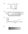
- FIG. 1A is a conceptual diagram (b) illustrating a depletion state of a source gas in a cylindrical hollow portion immediately after a negative bias voltage on-time (Ton) in a negative bias voltage application pattern, and (c). It is a graph.
- FIG. 1B is a (b) conceptual diagram illustrating a fully-filled state of the raw material gas in the cylindrical hollow portion after the elapse of the off time (Toff) in the negative bias voltage application pattern, and (c) a graph. is there.
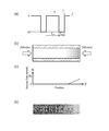
- FIG. 1C illustrates (b) a conceptual diagram, (c) a graph, and (d) illustrating the distribution state of the source gas in the cylindrical hollow portion in the first half of the on-time (Ton) in the negative bias voltage application pattern.
- FIG. 1D illustrates (a) a negative bias voltage application pattern, and (b) a conceptual diagram, (c) a graph, (d) illustrating a distribution state of a source gas in a cylindrical hollow portion in the latter half of an on-time (Ton).
- FIG. 1D illustrates (a) a negative bias voltage application pattern, and (b) a conceptual diagram, (c) a graph, (d) illustrating a distribution state of a source gas in a cylindrical hollow portion in the latter half of an on-time (Ton).
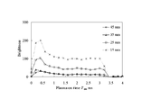
- FIG. 4 is a graph illustrating the influence of the ON time (Ton) of the negative bias voltage on the film thickness uniformity.
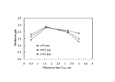
- FIG. 5 is a graph showing the relationship between the negative bias voltage OFF time (Toff) and the source gas depletion time Td.
- FIG. 6 is a conceptual diagram illustrating a configuration for simultaneously measuring two plasma emissions from a carbon-containing species derived from a source gas and a reference background gas species.
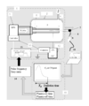
- FIG. 7 is a schematic view of a film forming apparatus as one embodiment.
- FIG. 7 schematically shows the configuration of the film forming apparatus 1 disclosed herein.
- the film forming apparatus 1 is essentially a film forming apparatus 1 that forms a thin film on a film forming object (structure 5) by using a plasma source gas.
- the film forming apparatus 1 is based on the so-called plasma CVD method, which forms a film by converting a raw material gas into plasma and depositing it on a film formation target.
- this film-forming apparatus 1 is comprised so that the thin film can be formed in the wall surface with the raw material gas converted into plasma especially in the said hollow part of the film-forming target provided with a cylindrical hollow part.
- plasma is generated by instantaneously forming an ultrahigh output field in a narrow region by superimposing a negative bias voltage on the microwave power during film formation.
- the microwave is propagated to the wall surface of the columnar hollow portion of the film formation target, and a negative bias voltage is applied to the wall surface in a pulsed manner to superimpose the columnar hollow portion.
- Plasma inner surface plasma
- this film-forming apparatus 1 originates in the plasma light emission derived from the raw material gas introduce
- the film forming apparatus 1 includes a data processing unit 11 that can perform time-resolved analysis of a light reception result and determine a depletion time and a recovery time.
- the “depletion time” means the time from when the raw material gas is exhausted to the exhaustion from the cylindrical hollow portion in which the raw material gas is sufficiently filled.
- the “recovery time” means the time until the source hollow is sufficiently filled in the cylindrical hollow portion in a depleted state.
- the source gas is sufficiently filled means that the source gas concentration in the cylindrical hollow portion reaches equilibrium with the source gas concentration in the outside (typically, inside the chamber 2) atmosphere. means.
- the film forming apparatus 1 controls the inner plasma on-time as the depletion time or more and the inner plasma off-time as the recovery time or more based on the depletion time and recovery time information obtained by the data processing unit 11.
- a plasma generation power supply control unit 15 capable of performing the above operation is provided.
- the technique disclosed herein generates the inner surface plasma for an appropriate time longer than the exhaustion time of the source gas in the cylindrical hollow portion, and then extinguishes the plasma for a time longer than the recovery time.
- the film formation is started in a state where the source gas in the hollow portion is kept constant at a desired concentration.
- film formation with a uniform thickness is realized on the inner wall of the cylindrical hollow portion.
- FIG. 1A shows a state in which no source gas is present in the cylindrical hollow portion of the film formation target, in other words, a state in which the source gas is exhausted during the film formation process.
- a state can be seen, for example, when the inner surface plasma is continuously generated and all the raw material gas is consumed. That is, it can be seen when the negative bias voltage is continuously turned on in the negative bias voltage application pattern (a).
- the concentration of the source gas in the cylindrical hollow part is almost zero. In such a state, film formation using the source gas is not performed.
- a film that has already been formed may be sputtered by a plasma such as a reference background gas.
- a plasma such as a reference background gas.
- FIG. 1B shows a state in which, in the film forming process, the cylindrical hollow portion of the film formation target is filled with the raw material gas to a predetermined concentration, and the raw material gas concentration is restored to the initial full state.
- a recovery (full filling) state for example, after the negative bias is switched off in the state (A), the source gas in the chamber 2 is supplied by diffusion into the depleted cylindrical hollow portion. This is seen when the source gas concentration in the inside and the source gas concentration in the cylindrical hollow portion are substantially the same (equilibrium).
- the film formation target is a pipe 5, and the source gas is supplied to the cylindrical hollow portion from both open ends in the axial direction of the pipe.
- the concentration of the raw material gas is constant in the axial direction of the cylindrical hollow portion.
- the negative bias is quickly switched on when such a recovery state is reached. That is, the inner surface plasma is generated to set the on time, and the film formation is started.
- FIG. 1C shows a state in which the raw material gas in the cylindrical hollow portion is consumed by the generation of the inner surface plasma in the film formation process.
- the state during the consumption is such that, by switching on the negative bias after the state (B), the inner surface plasma is generated in the cylindrical hollow portion in the recovery (full filling) state, and the source gas is consumed. You can see it when you go.
- the plasma density phase diagram of (d) the plasma density is higher on the microwave introduction side and becomes lower as the distance from the microwave introduction side increases.
- the concentration of the raw material gas is higher on the microwave introduction side where the plasma density is higher. It is low and increases as the plasma density decreases away from the microwave introduction side. This is because, according to the high-density plasma, the consumption of the source gas is sufficiently faster than the supply of the source gas from the chamber to the cylindrical hollow part and the diffusion in the cylindrical hollow part. It also shows that the consumption of raw material gas is ahead.
- FIG. 1D shows a state immediately before the source gas in the cylindrical hollow portion is depleted due to the generation of internal plasma in the film formation process.
- the state immediately before the depletion is, for example, further maintained by the inner surface plasma generated in the cylindrical hollow part by maintaining the negative bias on even after the state of consumption of the source gas in the above state (C). It can be seen when gas is consumed.
- the concentration of the raw material gas is almost zero on the microwave introduction side. Is the extent that some amount remains on the side opposite to the microwave introduction side.
- the source gas consumption by the high-density plasma in the cylindrical hollow portion is sufficiently faster than the supply of the source gas, and at the end opposite to the microwave introduction side
- the source gas is exhausted as in the microwave introduction side.
- the consumption of the raw material gas by the inner surface plasma is sufficiently faster than the supply, and even if the raw material gas can be supplied from both open ends of the cylindrical hollow portion, the supply can not keep up with the consumption. . Therefore, in the cylindrical hollow portion, the source gas is not supplied from the outside, and the source gas introduced from the beginning is consumed due to the generation of the inner surface plasma and the film formation, and thus it is inevitable that the cylindrical hollow portion falls into a depleted state. I understand that.
- a source gas exhaustion state is not a phenomenon that occurs only when high-density plasma is used.
- a source gas depletion state may occur depending on the size and shape of the cylindrical hollow portion, the configuration of the CVD apparatus, the setting conditions thereof, and the like.
- the inner plasma in the film formation process, the inner plasma is immediately turned off after confirming that the source gas is exhausted in the cylindrical hollow part, and the raw material is supplied to the cylindrical hollow part. After supplying the gas until it is fully filled, the inner surface plasma is turned on again. And based on the duty cycle by ON / OFF of such inner surface plasma, it is trying to make the film thickness of the film
- the film is formed by setting the ON time of the inner surface plasma to coincide with the depletion time from the generation of the inner surface plasma until the source gas is depleted, or by shortening it so as not to be shorter than the depletion time.
- the rate can be improved.
- the internal plasma off time is made to coincide with the recovery time at which the concentration of the raw material gas in the cylindrical hollow portion is sufficiently recovered, or shortened to a period close to the recovery time and optimized. The deposition rate can be improved.
- FIGS. 2 and 3 show the plasma emission when the negative bias voltage is turned on and the inner surface plasma is generated in a state where the cylindrical hollow portion is fully filled with the source gas and the reference background gas (see, for example, FIG. 1B). Intensity changes over time.
- FIG. 2 shows the plasma emission intensity derived from the reference background gas. In this example, Ar is used as the reference background gas.
- FIG. 3 shows the intensity of plasma emission derived from the source gas. In this example, a carbon-containing gas is used as the source gas, and the emission intensity of C 2 as an excited species of the gas is adopted. The negative bias voltage is turned off at 3.2 ms, and the inner surface plasma is extinguished.
- Internal plasma is generated by superimposing a negative bias voltage on the microwave power.
- the emission spectrum of Ar is detected together with the generation of inner surface plasma (0 ms), and is almost constant until the inner surface plasma is turned off after a very short time (approximately 0.5 ms in the example of FIG. 2). It becomes the value of. Since the reference background gas that does not contribute to the film formation is not consumed, the reference background gas filled in the cylindrical hollow portion is converted into plasma and then stabilized in a very short time (about 0.5 ms). It can be seen that the amount is maintained thereafter. In addition, the time until this becomes constant depends on, for example, the type of reference background gas, the shape of the cylindrical hollow portion, and the like. One source gas plasma is consumed as the film is formed.
- the raw material gas filled in the cylindrical hollow portion is turned into plasma in an extremely short time (in the example of FIG. 3, about 0.5 ms) to convert the raw material gas species (excited species, in this case, C 2 ).
- the raw material gas species excited species, in this case, C 2
- the emission intensity of the source gas species does not become zero but converges to a certain value. This is because a source gas species (C) is formed by sputtering a thin film on which a reference background gas species in the inner surface plasma and other excited species (which may be Ar ions, hydrogen atoms, and radicals) that do not contribute to film formation are formed.
- the plasma emission intensity ratio strongly depends on the plasma emission intensity of the source gas species (C 2 ). Therefore, the time until the source gas species (C 2 ) generated from the source gas disappears, and only the source gas species (C 2 ) sputtered from the formed thin film can be detected, in other words, the inner surface plasma
- the time from the generation until the initial determination that the value has settled to the certain value can be used as the source gas depletion time Td. Judgment whether the plasma emission intensity ratio has settled to a certain value (judgment of convergence) is unclear because it depends on the volume of the cylindrical hollow part of the film formation object and the sensitivity of the plasma emission measurement.
- the fluctuation of the plasma emission intensity ratio is approximately 50% or less of the maximum value of the intensity ratio, typically 30% or less, further 20% or less, such as 10% or less (more preferably 5% or less, such as 2 It can be used as a guideline.
- the change in the above-mentioned “change in the plasma emission intensity ratio” falls within 20% or less (eg, 10% or less, more preferably 5% or less, eg, about 2 to 3%) of the “change in the plasma emission intensity ratio”. It is good also as a standard.
- time-resolved analysis of the plasma emission intensity data of the reference background gas species (Ar) and the source gas species (C 2 ) measured by the light receiving optical system 7, FIG. 2 and the depletion time Td calculated from the example of FIG. 3 was approximately 1.6 ms.
- the gas is replenished before the raw material gas remaining in the cylindrical hollow portion is completely consumed.
- the consumption of the raw material gas has an inclination in the cylindrical hollow portion, and therefore it takes time until this becomes uniform by diffusion.
- the replenishment of the raw material gas is also due to diffusion, the replenishment of the raw material gas at a stage where the concentration gradient is small is inferior. Therefore, it is not preferable to start the film formation in a state where the source gas is not consumed because the film formation rate is greatly reduced.
- the ON time of the inner surface plasma is set so as not to be shorter than the depletion time Td.
- the inner surface plasma is turned off after the on time of the inner surface plasma becomes equal to or longer than the depletion time Td.
- the on-time (Ton) of the inner surface plasma is determined so as to be at or near the exhaustion time of the source gas. This is a preferred embodiment. With this configuration, it is possible to form a film with a more uniform film thickness in the axial direction and with a further improved film formation rate.
- the off time is shorter than the recovery time Tr, the source gas is not fully filled in the cylindrical hollow portion, and the amount of the reducing gas that can be used in the next film formation is reduced. Therefore, when the inner surface plasma is turned on next time, the raw material gas that can be consumed is small, and the depletion time is shortened. When the depletion time is shortened, the influence of the time required for rising of the inner surface plasma is increased, and the film formation rate is greatly reduced. In addition, the concentration of the source gas in the cylindrical hollow portion due to diffusion is not uniform, and the concentration of the source gas increases near the position where the source gas is supplied (typically, both ends in the axial direction of the cylindrical hollow portion).
- the concentration of the raw material gas becomes lower at a position away from the supply section (typically, the central portion in the axial direction of the cylindrical hollow section). Therefore, the film thickness of the film formed in the axial direction of the cylindrical hollow portion can be nonuniform. Therefore, such film forming conditions may be a form to be avoided. Therefore, in the technique disclosed herein, it is preferable to set the internal plasma off time to be longer than the recovery time Tr. In other words, the inner surface plasma is turned on after the inner plasma off time becomes equal to or longer than the recovery time Tr. Also with this configuration, it is possible to form a film with a uniform film thickness in the axial direction and an improved film formation rate.
- the inner plasma off time (Toff) is shortened to be at or near the recovery time Tr, and is optimal. It is a preferred embodiment. According to this configuration, the film can be formed with a more uniform film thickness in the axial direction.
- the structure 5 having a cylindrical hollow portion can be used as a film formation target, and the hollow portion wall surface (that is, the inner wall surface) of the film formation target is used as the film formation target.
- film formation can be performed on the inner wall surface of a cylindrical body typified by piping and valves. From the characteristics of the apparatus 1, the shape of the columnar hollow portion that is elongated or reduced in diameter so that the source gas can be depleted is a particularly suitable film formation target. .
- Such a form in which the source gas can be exhausted cannot be unequivocally described because it depends on the configuration of the CVD apparatus, plasma generation conditions, and the like, but typically, the inner wall of a cylindrical hollow portion having a diameter of 10 mm or less is used.
- the case where it is set as a film formation target is mentioned.
- the inner wall of the film formation target provided with a cylindrical hollow portion having a diameter of 10 mm or less (typically 8 mm or less, more specifically 5 mm or less, for example, 4 mm or less).
- the aspect ratio is a value expressed as b / a, where a is the diameter of the cylindrical shape of the hollow portion and b is the length in the axial direction, and the b / a is about 20 or less. It may be.
- a film having a b / a of 1 or more, typically 2 or more, preferably 5 or more, for example, 10 or more can be a suitable film formation target.
- the “columnar shape” is not limited to a geometrically strict columnar shape.
- the cross-sectional shape is a columnar shape that can be regarded as a substantially round shape, it can be included in the cylindrical shape in the present technology.
- the cross-sectional shape may include an ellipse, a polygon, and these variations.
- the columnar central axis may be a straight line, but may be somewhat curved.
- the basic configuration of the film forming apparatus 1 based on the plasma CVD method is not particularly limited, but for example, the configuration shown in FIG. 7 is preferably used. That is, the film forming apparatus 1 includes a chamber 2 that can form a vacuum environment for generating plasma, a gas inlet 6 for introducing a raw material gas that is a raw material of a target film into the chamber 2, and a chamber 2 A jig 4 for fixing the structure 5 to be formed into a film, a microwave generator 3 for introducing a microwave for plasma excitation into the structure 5 fixed by the jig 4, and A bias voltage power source 12 for applying a negative bias voltage to the structure 5 is provided as a main component.
- the film forming apparatus 1 is not particularly limited, but has an electron density of 10 7 cm ⁇ 3 or more and 10 15 cm ⁇ 3 or less (typically 10 8 cm ⁇ 3 or more and 10 14 cm ⁇ 3 or less, preferably It is preferably is a 10 10 m -3 or 10 13 cm -3 or less) that can be generated in the plasma configuration.
- the structure 5 to be formed is fixed to the jig 4, and the inside of the chamber is brought into an appropriate vacuum state, and then the source gas is introduced.
- a microwave for plasma excitation is introduced from the microwave generator 3 to the structure 5, and a negative bias voltage is applied to the structure 5 by the bias voltage power supply 12, thereby the structure 5.
- Plasma can be generated on the surface.
- plasma inner surface plasma
- plasma can be generated along the inner wall of the cylindrical hollow portion of the structure 5.
- constituent members do not characterize the present invention and can be the same as a known configuration such as plasma CVD, and thus further description thereof is omitted.
- the reference background gas is introduced together with the source gas to generate plasma.
- the source gas the same source gas as that used when a film having a desired composition is formed by a conventional plasma CVD method can be used. That is, a source gas species (which can be an excited species of atoms, molecules, ions, radicals, etc. of the source gas and its reactant) capable of forming a target film by plasma excitation (including formation by reaction) is generated. As long as it can be used, it can be used without particular limitation.
- the emission intensity derived from the source gas may be obtained by observing the emission line spectrum of any of these excited species.
- the raw material gas when forming a DLC film, can be used alone or in combination of two or more from various carbon (C) -containing hydrocarbon gases.
- C carbon
- Examples of such source gas typically include methane (CH 4 ), acetylene (C 2 H 2 ), benzene (C 6 H 6 ), toluene (C 6 H 6 CH 3 ), tetramethylsilane (Tetramethylsilane).
- TMS, Si (CH 3 ) 4 ) and the like are preferable examples.
- silicon carbide (SiC) film When a silicon carbide (SiC) film is formed, the above-mentioned carbon-containing hydrocarbon gas, silicon-containing gas such as silane (SiH 4 ), tetramethoxysilane (Tetramethyl orthosilicate: TMOS, SiC 4 H) is used as a source gas. 12 O 4 ), alkoxysilane gas such as tetraethoxysilane (TEOS, SiC 8 H 20 O 4 ), etc., can be used alone or in combination of two or more. In this case, it is preferable to use at least one emission line spectrum of Si, SiH, H, H 2 or the like for the time-resolved analysis of the emission intensity. Further, together with these gases, a carrier gas that does not contribute to film formation can be simultaneously supplied.
- silicon-containing gas such as silane (SiH 4 ), tetramethoxysilane (Tetramethyl orthosilicate: TMOS, SiC 4 H)
- the reference background gas a gas that does not contribute to film formation and that can generate stable excited species by plasma excitation can be preferably used.
- the plasma emission intensity related to the source gas is affected by slight fluctuations in the plasma flame. Therefore, by adding a reference background gas having a known concentration as an internal standard, the emission intensity of the source gas can be accurately quantified as an intensity ratio with respect to the emission intensity of the reference background gas.
- a gas for example, a rare gas such as helium (He), neon (Ne), argon (Ar), krypton (Kr), or the like is preferable.
- This reference background gas may serve as a carrier gas in the plasma CVD method.
- time-resolved analysis is performed using the intensity ratio of Ar to the emission line spectrum.
- the light receiving optical system 7 it is possible to use without particular limitation what can measure the time response characteristics of the target plasma emission intensities of two or more wavelengths in units of femtoseconds, picoseconds or nanoseconds, for example. it can.
- the light receiving optical system 7 basically has a function of selecting light derived from the source gas and light derived from the reference background gas from plasma emission.
- Spectroscopic means such as a bandpass filter, a grating (diffraction grating) 16 and a spectroscope, and an ultraviolet detector, a visible detector, a photodiode detector, and a photodiode array that convert the intensity of the selected light into an electric signal.
- a light-receiving element such as a detector, a photomultiplier tube, and a linear array photomultiplier tube.
- a light receiving optical system 7 for example, after the spectral decomposition of the light derived from the source gas and the light derived from the reference background gas by the grating (diffraction grating) 16 from the emission of the inner surface plasma, these selected spectra are used. Can be received by the linear array type photomultiplier tube 20. The obtained signal can be sent to a data processing unit 11 described later by wired or wireless communication via the optical fiber 8 or the like.
- the light receiving optical system 7 removes excess light, for example, a mirror 18 that changes the path (optical axis) of plasma emission, a lens 17 that converges diffused light, as shown in FIG. Needless to say, a filter (not shown) or the like may be provided.
- the linear array photomultiplier exemplified in FIG. 6 is preferably a photodiode array.
- the light receiving optical system 7 is preferably a confocal optical system.
- the confocal optical system can receive, with a point detector, light that has been point-illuminated on the surface of the object to be measured.
- the light receiving element is a combination of a point detector and a pinhole having an appropriate opening.
- the position of the lens 17 is adjusted so that the plasma emission is focused on the light receiving element from a predetermined position of the measurement object. As a result, almost all of the plasma emission from the predetermined position reaches the point detector through the pinhole and spreads without converging on the light receiving element surface. It cannot pass and is not received.
- plasma emission at a desired position (focused position) of the cylindrical hollow portion can be obtained as a highly reliable signal without being affected by unnecessary scattered light or the like. That is, for example, by installing a confocal optical system on the axial extension of the cylindrical hollow portion and setting the focal point to an arbitrary local region (local point) of the cylindrical hollow portion, Only light emission can be received by the optical system.
- a confocal optical system is more preferably a long-focus optical system capable of focus adjustment at a distance of 200 mm or more (typically 300 mm or more, preferably 500 mm or more, for example 700 mm or more).
- the light receiving element may be configured by an image display device such as a high-speed camera, a CCD camera, or a streak camera provided with the light receiving element.
- the data processing unit 11 analyzes the light reception result (signal) obtained by the light receiving optical system 7 based on time-resolved spectroscopy (TRS), and can calculate the depletion time and the recovery time.
- Any device having a function can be used without particular limitation.
- a computer 10 having a configuration in which a central processing unit (CPU), a main storage device, an auxiliary storage device, and the like are connected by a bus can be preferably used.
- the source gas and the reference background in an extremely short time region (for example, about 10 ⁇ s to 1 s, preferably about 50 ⁇ s to 1 s, more preferably about 0.1 ms to 10 ms).
- the plasma generation power control unit 15 uses the inner plasma on time as the depletion time and the inner plasma off time as the recovery time based on the depletion time and recovery time information obtained by the data processing unit 11. As long as it can be controlled as follows. For example, the frequency and duty cycle for generating the inner surface plasma are calculated from the on time and the off time in the duty ratio pulse frequency determining unit 14 and the like, and based on the frequency and duty cycle, the power source control unit 15 for plasma generation is calculated. In this way, film formation can be performed by repeatedly generating the inner surface plasma.
- the plasma generation power source control unit 15 can be configured by, for example, a combination of a function generator 13 and a switch controller, for example.
- the film forming method disclosed herein can be embodied as including the following steps (1) to (7).
- the sixth step is repeated at the frequency and duty cycle calculated from the on-time and off-time of the inner surface plasma optimized to maximize the film formation rate and minimize the film thickness distribution. 7th step to film.
- the on-time and off-time of the inner surface plasma in the steps (1) to (6) will be described based on a specific embodiment.
- film formation is advanced by a duty cycle in which plasma is continuously turned on / off.
- the on time and off time in the on / off state are respectively represented as Ton (n) and Toff (n).
- Ton (n) and Toff (n) Ton
- Toff (n) Ton
- the on time and the off time are optimized in the first stage of the film forming cycle.
- the generation of the inner surface plasma is realized by superimposing the microwave power introduced into the film formation target and the negative bias voltage. Therefore, in actual operation, on / off of the inner surface plasma may be controlled mainly by turning on / off the negative bias voltage.
- Ton (1) and Toff (1) are preferably set within a range that is not too short.
- the plasma emission of the source gas species may be emission based on any excited species included in the source gas plasma. For example, when the source gas is a carbon-containing gas (for example, CH 4 or the like), it is preferable to select and receive C 2 plasma emission.
- the spectroscopic techniques and signal amplification techniques up to that point are There is no particular limitation.
- the emitted light is converted into an electric signal by the light receiving optical system 7 (for example, a light receiving element) and sent to the data processing unit 11 provided in the personal computer 10, for example.
- Step (3); Measurement of depletion time based on time-resolved analysis the data processing unit 11 performs time-resolved analysis on the light reception result sent from the light receiving optical system 7, and determines the depletion time Td of the source gas species.
- Such data transmission / reception is preferably performed in real time.
- the depletion time Td can be determined as follows. That is, as described above, the emission intensity based on the reference background gas (eg, Ar) and the source gas (eg, CH 4 ) converges to a constant value as the internal plasma on-time elapses, and the emission intensity ratio is Also converges to a constant value.
- the intensity ratio decreases with the passage of the on-time of the inner surface plasma, and the fluctuation is approximately 50% or less, typically 30% or less, further 20% or less of the maximum intensity ratio, for example, When it becomes 10% or less (more preferably within 5%, for example, about 2 to 3%), it can be determined that convergence has occurred.
- the time from plasma on (0 ms) to the convergence can be set as the first cycle depletion time Td (1).
- Td (1) 1.6 ms was obtained as the depletion time Td (1).
- the depletion time Td (1) is calculated by the data processing unit (calculation unit) 11 and stored in the storage unit.
- the initial value of the on-time of the inner surface plasma is shortened and the optimum value is determined within a range that does not affect the above-determined source gas species depletion time.
- Ton (1) Ton (1)
- the DLC film formed in the first cycle can be peeled off by generating an inner surface plasma in a reference background gas atmosphere before performing the first cycle again.
- Ton (1) can be made based on, for example, whether Td (1) is within a range of ⁇ 10% of Ton (1). As described above, it is generally performed in this type of algorithm that an allowable range of, for example, about ⁇ 10% may be provided for the determination.
- the number of times the inner surface plasma is turned on / off based on Ton (1) and Toff (1) is determined by time-resolved analysis and the above-described Ton (1) from the measurement of emission intensity. It can be determined as appropriate in consideration of the time required to determine whether or not there is.
- the number of internal plasma generations (number of on / off times) in one cycle may be adjusted according to the calculation capability of the data processing unit 11.
- the first cycle is fixed to the number of on / off times of the inner surface plasma (for example, the number of on / off times of 10 (10 pulses) as an example) for which the data processor 11 can calculate the depletion time Td (1).
- the number of on / off times is preferably one (one pulse).
- the end of the first cycle can be determined when it is determined whether Ton (1) is appropriate.
- the number of on / off operations performed in the first cycle is one, but is not limited thereto. Note that the number of plasma on / off operations performed in the following nth cycle is not strictly defined and can be set as appropriate. Hereinafter, the number of internal plasma generations (on / off times) in the n-th cycle can be similarly adjusted.
- Toff (1) has a sufficient time to fully fill the source gas depending on whether Td (2) in the second cycle is shortened.
- the depletion time Td in the second cycle is also based on the time decay of the emission intensity spectrum for the on-time of the second cycle in the same manner as in the first cycle (that is, in the same manner as in the second step and the third step). (2) is calculated.
- the Td (2) data is stored in the storage unit.
- Toff (1) is reset, and the film is formed after returning to the first cycle (that is, in the same manner as in the first to third steps).
- the DLC film formed in the first cycle can be peeled off by generating the inner surface plasma in the reference background gas atmosphere. It is possible to form a film with a more uniform film thickness distribution in a cycle.
- Ton (n) Ton (1), (n ⁇ 3)
- Steps (5) and (6); Toff reduction and optimization In the fifth step, the initial value of the internal plasma off time is shortened within a range that does not affect the depletion time Td of the source gas species determined above. Then, by repeating the shortening while judging (determining) whether or not such shortening is appropriate, the optimum value of the off time of the inner surface plasma is determined. In other words, the off time is optimized by repeatedly performing the second step, the third step, and the fifth step with the determination interposed therebetween.
- the optimization of Toff (n) can be performed from the off time of the second cycle. That is, since it has been confirmed that the initial value Toff (1) of the off time is sufficiently long in the on time of the second cycle, the off time is set to the initial value while sufficiently filling the source gas thereafter. To see how much can be shortened. In other words, the range in which the off time can be shortened without reducing the depletion time Td is examined.
- Toff (2) a value obtained by subtracting a preset shortening period ⁇ toff from Toff (1) is adopted as Toff (2).
- Toff (n) Toff (n ⁇ 1) ⁇ toff
- Td (n) Td (n ⁇ 1)
- the OFF time can be repeatedly reduced until Td (n) ⁇ Td (n ⁇ 1) in the third and subsequent cycles (n ⁇ 3).
- Td (n) ⁇ Td (n ⁇ 1) in the third and subsequent cycles it can be determined that the previous off time Toff (n ⁇ 1) is not a sufficiently long value. For example, if Td (3) ⁇ Td (2) in the third cycle, it is considered that the off time Toff (2) of the second cycle has become too short due to the shortening. Therefore, in such a case, the off time Toff (n) in the nth cycle is added to the off time Toff (n ⁇ 2) two cycles before by adding ⁇ toff instead of reducing Toff (n ⁇ 1). return.
- Such optimization is not particularly limited, but typically, it is preferably performed with a time of about 1/100 or less of the time required for film formation as a guide. Further, by performing 6 cycles or more (for example, 6 ⁇ n ⁇ 10), it is possible to determine the optimum Ton and Toff with higher accuracy.
- the off time Toff (n) in the nth cycle is 2
- the optimization may be performed based on the smaller shortening time ⁇ toff ′ from the off time Toff (n ⁇ 2) before the cycle.
- Toff (n) is as follows.
- Toff (n) Toff (n ⁇ 2) ⁇ toff ′
- Td (n) Td (n ⁇ 1), n ⁇ 3
- Toff (n) Toff (n ⁇ 2)
- Toff (n) Toff (n ⁇ 2)
- Toff (n) can be regarded as the recovery time Tr.
- Step (7) Film formation under optimum conditions
- the on-time and off-time of the inner surface plasma optimized so as to maximize the film formation rate and minimize the film thickness distribution are calculated.
- the film is repeatedly formed at the frequency and duty cycle based on the optimized on time and off time. As a result, a film having a uniform thickness can be formed at a high rate in the axial direction of the cylindrical hollow portion.
- the inner gas is turned on / off (switched) once to use all of the raw material gas fully filled in the hollow cylindrical portion. It is important to ensure that the raw material gas is fully filled as soon as the raw material gas is exhausted. Such filling is based only on the diffusion action of the source gas. Therefore, in the film formation by repeatedly turning on / off the inner surface plasma, it is important to suppress the problem of the diffusion of the source gas (filling failure). Therefore, it is preferable to measure the plasma emission ratio at a point where the source gas is most difficult to reach due to diffusion.
- the light receiving optical system recovers the concentration of the source gas species at the latest in the cylindrical hollow portion as an arbitrary measurement region of the plasma emission of the source gas species or its reaction product species and the plasma emission of the reference background gas species. It may be a preferred embodiment to select the region. Such a region to be measured can typically be a point farthest from the open part of the cylindrical hollow part. Typically, for example, when the film formation target is a tubular structure and the source gas can be supplied from both ends in the tube axis direction, the measurement target region is near the center of the tubular structure in the tube axis direction. Is preferable. In order to measure only the emission intensity from such a local measurement region, it is preferable to use a confocal optical system as described above.
- the film forming method disclosed herein may further include a thin film removing step and a step of authorizing (confirming) the completion of the thin film removing step.
- the thin film removal step can be realized by stopping the introduction of the source gas into the chamber and generating the inner surface plasma in the atmosphere of the reference background gas species (and carrier gas).
- the preliminarily formed thin film can be sputtered by the excited species of the reference background gas species (and carrier gas) and peeled off from the film formation target.
- Such a peeling step can be performed at an arbitrary timing.
- a thin film that tends to be uniform can be peeled off.
- the step of confirming the completion of the thin film removal step is not an essential process, it is preferable to carry out the step subsequent to or in parallel with the above thin film removal step.
- the plasma emission intensity from the source gas species derived from the thin film generated by the sputtering and the reaction product species is measured by, for example, the light receiving optical system 7, and the emission intensity is a predetermined value.
- Completion of said thin film removal step is confirmed by being less than (threshold).
- a threshold can be appropriately determined according to the emission intensity of the excited species derived from the thin film, the accuracy of the light receiving optical system, and the like.
- the fluctuation of the emission intensity of the excited species derived from the thin film is 50% or less of the maximum intensity, preferably 30% or less, more preferably 20% or less, for example 10% or less (typically about 5% or less). (For example, about 3% or less), it can be determined that the removal of the thin film is completed.
- the technique disclosed herein implements the above steps (1) to (6) under predetermined film formation conditions for a film formation target of a predetermined standard (size, material, etc.) having a cylindrical hollow portion. By doing so, it can be grasped as a method of optimizing the on-time and off-time of the inner surface plasma during film formation on the film formation target.
- the technique disclosed herein forms a film on the inner wall of a film formation target of a predetermined standard having the cylindrical hollow portion based on the on-time and off-time of the inner surface plasma obtained by the optimization method.
- the optimum values of the on-time and off-time are measured in advance for a desired film formation target, the optimum values of the on-time and off-time are adopted for the second and subsequent film formation. Only film formation can be performed.
- the on-time and off-time are optimized by performing the above steps (1) to (6) for a rougher (rougher) film-forming target with a predetermined standard (dimension). Under such conditions, the film can be formed on the target film having a more precise finish.
- the technique disclosed herein is a film forming method for forming a thin film by depositing a source gas that has been made plasma in a cylindrical hollow portion by turning on and off the plasma on the wall surface of the cylindrical hollow portion.
- Such a film formation method can be performed by repeating on / off of the plasma in a pulsed manner based on the on-time Ton and off-time Toff of the optimized plasma.
- this optimization process is realizable as what includes the following processes, for example.
- Such optimization processing is performed for the on-time Ton (n) and the off-time Toff (n) of the nth cycle plasma.
- the ON time and OFF time optimized easily are obtained.
- the source gas is generated and extinguished in a state where the source gas and the reference background gas are introduced into the cylindrical hollow portion.
- the above-mentioned film formation can be suitably performed by generating the plasma and depositing the plasma of the source gas on the wall surface of the cylindrical hollow portion.
- Example 1 In this embodiment, a sufficiently long stainless steel cylindrical pipe 5 having a diameter of 1/4 inch, an inner diameter of 4.4 mm, and a length of 50 mm is prepared as a film formation target, and a DLC thin film is formed on the inner wall of the pipe 5. It was decided.
- the film forming apparatus 1 having the configuration shown in FIG. 7 was used. The film forming procedure was as follows.
- a DC pulse power source 12 is connected to the fixed structure 5 and a negative bias voltage is applied to the wall surface of the cylindrical hollow portion.
- a microwave power source 3 and a waveguide for allowing microwaves to enter from the opening into the cylindrical hollow portion are connected to the chamber 2. The power of the microwave and the negative bias voltage are turned on / off with a predetermined power and voltage in response to a signal from the function generator 13.
- the pressure in the chamber is adjusted to 30 Pa
- the source gas such as CH 4 , C 2 H 2, benzene, toluene, tetramethylsilane, or a mixed gas thereof
- the reference background gas are added to the chamber 2.
- a plasma capable of separating the raw material gas species of the thin film is generated.
- a thin film for example, a DLC film is formed on the wall surface of the cylindrical hollow portion.
- CH 4 gas and TMS gas were used as the source gas
- Ar gas was used as the reference gas.
- the flow rates of these gases during film formation are CH 4 gas: 2 sccm, TMS gas: 0.2 sccm, Ar gas: 14 sccm, and a sufficient amount of source gas is filled in the pipe 5 at a uniform concentration at the start of film formation. It was in a state that has been. Further, the microwave for plasma excitation was generated under conditions of a peak power of 800 W, a frequency of 800 Hz, and a duty ratio of 10%.
- Film formation based on the plasma CVD method is performed by turning on / off microwave power output and negative bias voltage application.
- the on / off timing control selects plasma emission from C 2 as the carbon-containing species derived from the source gas, and determines the depletion behavior of the source gas species from the intensity ratio of the plasma emission from the reference background gas species Ar. Observe and do based on the results.
- the observation of the depletion behavior is performed using a light receiving optical system that enables observation of the intensity ratio at an arbitrary local point in the cylindrical hollow portion.
- the structure of the light receiving optical system 7 is various, for example, in the case of film formation on the inner surface of a stainless steel cylindrical pipe having a diameter of 1/4 inch and a length of 50 mm, it is desirable to use a confocal optical system.
- a long-focal confocal condensing optical system is uniquely constructed following the well-known long-focus optical system so that the emission intensity of the plasma emission near the center of the pipe axis of the pipe is possible. Used.
- confocal optics is used so that a local point on the cylinder axis is at the same distance from both ends of the structure 5. The system is adjusted.
- the plasma emission of C 2 and Ar guided by the confocal optical system is dispersed by a grating and a movable multi-slit 19 through an optical fiber, and the intensity thereof is measured by a linear array photomultiplier tube 20 (FIG. 6).
- a photomultiplier tube As this photomultiplier tube (PMT), a 16-channel photomultiplier tube (Hamamatsu Photonics Co., Ltd.) capable of simultaneously detecting a maximum of 16 types of wavelengths (information) dispersed through the spectroscope 9 or the like. Manufactured and specially manufactured products).
- Other configurations include, but are not limited to, a combination of a band-pass filter and a high-speed camera for selecting the wavelengths of the two plasma emissions, or a spectroscope and a CCD camera with an image intensifier.
- the time until the source gas species is depleted at the local point during the ON time of the inner surface plasma is determined, and the ON time of the inner surface plasma, that is, the ON state of the microwave power and the negative bias voltage is determined with reference to this.
- the (application) time (T on ) is determined. Optimization of the T on is by Ar ions and hydrogen atoms generated by the post of the raw material gas species depletion also continue on the inner surface plasma, leading to the effect of suppressing the sputtering or etching of thin films once deposited. Also, off-time of sufficient internal surface plasma to replenish the raw material gas species consumed during T on, i.e., determining the microwave power and the negative bias voltage off (non-application) time (T off).
- T off shortens the off time of the inner surface plasma that does not contribute to the film formation, and contributes to the improvement of the film formation rate.
- the optimal T off may be set to a time sufficiently longer than the time required for replenishing the source gas species.
- the optimized duty cycle based on the combination of T on and T off contributes to uniform film thickness.
- the plasma emission intensity ratio of the Ar atoms is a reference gas species and C 2 molecule is a carbon-containing species derived from the raw material gas and time-resolved analysis, the ratio is T on (1
- the emission intensity ratio between the C 2 molecule that is the carbon-containing species derived from the source gas in the inner surface plasma and the Ar atom that is the reference gas species converges to a constant value while the inner surface plasma is on.
- the plasma emission intensity of the reference background gas species Ar that does not contribute to gas is almost constant because Ar is not consumed (FIG. 2), whereas the plasma emission intensity of C 2 , which is a carbon-containing species derived from the source gas, is the source gas. Although it decreases with time due to consumption, it eventually settles to a constant value (FIG. 3).
- T d is the time until C 2 generated from the gas phase disappears, that is, the depletion time of the raw material gas, and in this embodiment, it can be determined as approximately 1.6 ms as shown in FIGS. .
- T on (1) 250 ms.
- T d (2) in T on (2) is calculated and stored in the same manner as in the previous step.
- T off (2) a value obtained by subtracting a preset ⁇ t off from T off (1). That is, the following equation is satisfied. In this embodiment, it is set to 50 ms.
- T off can be optimized more accurately by using a smaller value.
- T off (n) T off (n ⁇ 1) ⁇ t off
- T d (n) T d (n ⁇ 1).
- T off (n) is added instead of reducing ⁇ t off from T off (n ⁇ 1). Return to T off (n-2) two cycles ago. That is, the following equation is satisfied.
- Ton (n) performed in parallel is as follows.
- T on (1) T d (1) is determined as described above.
- T off (1) T d (1), T on (1) may not be a sufficiently long value, so the film forming process is stopped and T on (1) is reset. .
- the effect of optimization of the T on and T off obtained through the above steps was examined under the conditions of the present embodiment.
- the on-time (Ton) is fixed to four values in the range of 0.5 ms to 4 ms, and other conditions are the same.
- a DLC film was formed.
- FIG. 4 shows a result of measuring the film thickness in the axial direction of the cylindrical hollow portion of the DLC film formed at this time. The film thickness was measured at 5 mm, 25 mm, and 45 mm from the end of the pipe 5 on the side where the microwave was introduced.
- the film thickness was in the range of 2.3 ⁇ m to 2.4 ⁇ m at any of the above positions. Film thickness distribution of the cylinder axis direction as compared to other T on is the most uniform, it can be confirmed by this effect of optimization of the T on and T off obtained through the aforementioned steps
- FIG. 5 shows the source gas determined by measuring the plasma emission intensity of C 2 , which is a carbon-containing species derived from the source gas, at a position 25 mm from the microwave injection end for plasma excitation, with T off on the horizontal axis. It is the figure which plotted the depletion time of. As a result, exhaustion time of the feedstock gas, the case of the T off time shorter than 100ms, and to decrease in response to T off, in the case of longer than 100ms time, was almost constant (Fig. 5) .
- T off is, since the raw material gas species lower than the time required for being refilled inside the cylindrical pipe, a predetermined raw material gas species the partial pressure (concentration) of the chamber into the T off at the measurement point This is because the time until the material gas is exhausted is shortened. That is, in this example, it is determined that the time required for recovering the partial pressure of the source gas species (that is, the recovery time Tr) is 100 ms, and in order to form a uniform film, T off is longer than 100 ms. It must be set to.
- a DLC film having a uniform film thickness in the longitudinal direction of the cylindrical pipe is obtained by on / off control of the microwave power and the negative bias voltage by the plasma generation power supply controller using the frequency and duty cycle calculated from these as parameters. Was deposited.
- T on and T off is the on-time of the inner surface plasma and off-time, and by extension, frequency and duty cycle for generating the internal surface plasma in pulses, with respect to the optimization process, the actual film forming process
- frequency and duty cycle for generating the internal surface plasma in pulses with respect to the optimization process, the actual film forming process
- the formed DLC film to introduce the process of removing using a sputtering by Ar ions. Specifically, the introduction of the source gas species into the cylindrical hollow portion is blocked, and only Ar plasma is generated. In this embodiment, the introduction of CH 4 into the chamber is interrupted, and a negative bias voltage is applied to the wall surface of the cylindrical hollow portion as the microwave is turned on.
- the plasma emission of C 2 molecules generated by sputtering with Ar plasma is time-resolved. Then, it is determined that the DLC film has been removed when the plasma emission intensity of the C 2 molecule becomes a predetermined value or less, and the microwave application and the application of the negative bias voltage are stopped. Then as described above, it performs a negative bias voltage drive and the microwave is turned on by the plasma generation power source control unit the frequency and the duty cycle is calculated from the optimized T on and T off as a parameter, the longitudinal direction of the cylindrical hollow portion A DLC film having a uniform thickness is formed.
- the utility value is high in the field of industrial piping materials.
Landscapes
- Chemical & Material Sciences (AREA)
- Physics & Mathematics (AREA)
- Engineering & Computer Science (AREA)
- Plasma & Fusion (AREA)
- Materials Engineering (AREA)
- Chemical Kinetics & Catalysis (AREA)
- General Chemical & Material Sciences (AREA)
- Mechanical Engineering (AREA)
- Metallurgy (AREA)
- Organic Chemistry (AREA)
- Spectroscopy & Molecular Physics (AREA)
- Analytical Chemistry (AREA)
- Electromagnetism (AREA)
- Chemical Vapour Deposition (AREA)
- Plasma Technology (AREA)
Abstract
原料ガスの均一な分布を妨げる長尺又は高アスペクト比の円柱状中空部の壁面に対し、該円柱状中空部の長手方向に均一な膜厚にて成膜するための成膜装置及び成膜方法を提供する。かかる成膜装置及び成膜方法では、プラズマ化した原料ガス種またはその反応生成種及び背景ガス種の発光を、一例として、共焦点光学系を介した受光光学系を用いて時間分解計測することにより、任意の局所点における原料ガスの枯渇をリアルタイムにモニタリングし、該モニタリング結果をプラズマのオン/オフのタイミングとしてプラズマ発生用電源制御部にフィードバックする。
Description
本発明は、円柱状中空部の壁面に、プラズマ化した原料ガスにより薄膜を形成する方法及びその装置に関する。
本出願は、2013年3月25日に出願された日本国特許出願2013-063113号に基づく優先権を主張しており、その出願の全内容は本明細書中に参照として組み入れられている。
本出願は、2013年3月25日に出願された日本国特許出願2013-063113号に基づく優先権を主張しており、その出願の全内容は本明細書中に参照として組み入れられている。
配管やバルブ等の円柱状中空部の壁面のクリーン度向上に加え、耐食性等の機能向上のための均一な膜厚による成膜技術として、プラズマ化学蒸着(Chemical Vapor Deposition:CVD)法が注目されている。このプラズマCVD法を用いて円柱状中空部の壁面に該円柱状中空部の長手方向に均一な膜厚にて成膜するためには、原料ガスを円柱状中空部全体に均一に存在させる必要がある。円柱状中空部の開口部からの拡散による原料ガス供給の速度と比べて、プラズマ化及び成膜による原料ガスの分解・消費の速度が遅い場合には、原料ガスの円柱状中空部の長手方向の分布は、プラズマの有無に大きな影響を受けず、その均一性を高めることが可能である。
しかし、産業上利用される円柱状中空部を有する構造物は、長尺化や小径化によりそのアスペクト比は高くなる傾向にあり、さらに、主に円柱状中空部の壁面に沿って生成するプラズマ(以下「内面プラズマ」という。)の密度を高くすると、相対的に、拡散による原料ガス供給の速度に比べてプラズマ化による原料ガスの分解・消費速度のほうが速くなり、原料ガスの円柱状中空部内における長手方向の分散が不十分となり均一な膜厚にて成膜することが著しく困難となる。そこで、円柱状中空部の全体で原料ガスが該円柱状中空部の長手方向に均一に存在しているか否かをモニタリングし、これを成膜の制御にフィードバックする簡易な手法が必要になる。ところが、これがないために、過度の実験によるトライアンドエラーを通して均一な膜厚を得るための成膜条件を決定する必要があった。
特許文献1においては、膜厚の均一化に関する従来技術として、導電性加工物が陰極として機能するよう該加工物と陽極との間に電圧バイアスを印加するバイアスシステムと、該バイアスシステムの監視用に該加工物の内部に発生させたプラズマの強度を光学プローブとラングミュアプローブを用いてモニタリングする構成が記載されている。しかし、該モニタリング結果は、該加工物内部への原料ガスの導入を起動する制御システムに対しフィードバックされるものである。そして、その制御は、ガスフローとポンピング速度の制御による該加工物内部の原料ガス圧力を、その電子平均自由行程との関係において制御するという極めて複雑なものである。
なお、内面プラズマをパルス状に発生させる従来技術としては、例えば、円柱状中空部の壁面に接地電位に対する負バイアス電圧を印可してホローカソードプラズマを発生させたい場合には、該負バイアス電圧をパルス状にオン/オフする方法がある。また、同様の技術として、マイクロ波伝搬と前記負バイアス電圧の印加の重畳効果を利用する場合には、マイクロ波発生電源からの電力と前記負バイアス電圧をパルス状にオン/オフする方法がある。
特許文献2においては、プラズマ中における活性種からの特定波長光の発光強度信号を検出し、該信号を被処理体に対するプラズマ処理の終了を検知する方法が開示されている。しかし、膜厚の均一化のためのフィードバックシステムについては開示されていない。
特許文献3においては、被処理部材の内部にプラズマ誘導手段、例えばアンテナに代表される線状の導電体を被処理体の内部に設置することで、被処理体の内部に均一なプラズマの発生を誘導する技術が開示されている。しかし、該均一なプラズマの発生とこれにより成膜される膜厚の均一性との具体的な関係及びその制御については開示されていない。
特許文献4においては、配管等に十分な長さを有する環状部材であって、所定電圧が印加される該環状部材の内部空間に電磁波励起プラズマを誘導し、該プラズマにより被処理体である該環状部材の内壁面を処理する方法と装置が開示されている。しかし、環状部材の長さ方向に均一な膜厚にて成膜する技術については開示されていない。
そこで、本発明では、円柱状中空部内においてプラズマ化した原料ガスからの発光を解析することにより、その解析結果に基づいて行う内面プラズマのオン/オフ時間の制御のみで、円柱状中空部の壁面への該円柱状中空部の長手方向に均一な膜厚にて成膜を可能とする装置構成及びその方法の提供を目的とする。
第一発明は、円柱状中空部内においてプラズマ化した原料ガスにより、該円柱状中空部の壁面に薄膜を形成するための成膜装置であって、前記円柱状中空部内に導入される原料ガス種又はその反応生成種と参照用背景ガス種のプラズマ発光を同時に受光する受光光学系と、前記受光結果から前記二つのガス種からのプラズマ発光の強度比を時間分解分析し、前記円柱状中空部内における前記原料ガス種の枯渇時間と回復時間を決定するデータ処理部と、プラズマ発生のために前記内面プラズマの発生している時間(以下、「内面プラズマのオン時間」という。)を前記枯渇時間以上として、同じく内面プラズマが消失している時間(以下、「内面プラズマのオフ時間」という。)を前記回復時間以上として制御するプラズマ発生用電源制御部とを有することを特徴とする。
その構成としては、例えば、前記二つのガス種の波長をそれぞれ選択するバンドパスフィルターと高速度カメラ、分光器とプラズマ発光を測定する受光素子、又は、分光器とイメージインテンシファイヤ付きCCDカメラ等の組み合わせがあり、これらに限らない。一例として、ダイヤモンドライクカーボン膜(DLC膜)のような炭素系薄膜の成膜においては、原料ガス種の分解を経て生ずるC2又はCHなどの炭素含有種、及び、参照用背景ガス種Arからのプラズマ発光をグレーティングによりスペクトル分解したのちリニアアレイ型光電子増倍管でこれらを受光し、得られたシグナルをコンピュータにより時間分解分析処理する。
第二発明は、前記受光光学系が、前記原料ガス種又はその反応生成種及び参照用背景ガス種のプラズマ発光の任意の被測定領域として、前記円柱状中空部内において最も遅く前記原料ガス種の濃度が回復する領域を選定可能とする光学系であること、を特徴とする前記第一発明として記載する成膜装置である。
一例として、円柱状中空部が直管形状であって両端が開口しており、原料ガスを両開口部から導入する構成の場合、該円柱状中空部の円筒軸上かつその両端から等距離に位置する点を共焦点光学系の焦点とする受光光学系を用いることで、該焦点の局所領域からの発光のみを受光することが可能である。
第三発明は、円柱状中空部内においてプラズマ化した原料ガスにより、該円柱状中空部の壁面に薄膜を形成する成膜方法であって、初期値として定めた内面プラズマのオン時間とオフ時間により、成膜を開始する第1ステップと、前記原料ガス種又はその反応生成種のプラズマ発光と参照用背景ガス種のプラズマ発光とを、受光光学系により同時に受光する第2ステップと、前記受光結果を時間分解分析し、前記円柱状中空部内における前記原料ガス種の枯渇時間と回復時間を認定する第3ステップと、前記認定した原料ガス種の枯渇時間に影響を与えない範囲において、前記内面プラズマのオン時間の初期値を短縮し、その最適値を決定する第4ステップと、前記認定した原料ガス種の枯渇時間に影響を与えない範囲において、前記内面プラズマのオフ時間の初期値を所定時間短縮する第5ステップと、前記第2ステップ、第3ステップ及び第5ステップを繰り返し行い、前記内面プラズマのオフ時間の最適値を決定する第6ステップと、前記第6ステップにより、成膜レートが最大且つ膜厚分布が最小になるようにそれぞれ最適化された前記内面プラズマのオン時間とオフ時間から算出される周波数とデューティーサイクルにて繰り返し成膜する第7ステップとを有することを特徴とする。
ここで、前記原料ガス種の枯渇時間に影響を与える場合とは、例えば、成膜に寄与する前記原料ガス種が前記円柱状中空部内に残存しているにもかかわらず内面プラズマをオフにすることで、原料ガス種を枯渇しきらない場合や、内面プラズマがオフの間に、前記原料ガス種が前記円柱状中空部内に再度補充されるところ、その補充が十分でないまま内面プラズマを再びオンにしてしまうことで、同じく、原料ガス種の枯渇時間が本来よりも短くなってしまう場合をいう。そして、いずれの場合も成膜レートを低下させ、かつ、円柱状中空部の長手方向の膜厚分布を不均一にする要因となる。
第四発明は、前記第6ステップと第7ステップの間に、前記第1ステップから第6ステップの段階で成膜されてしまった、膜厚の不均一な薄膜を、前記円柱状中空部内への原料ガスの導入を停止した状態において、該薄膜をスパッタリング可能な参照用背景ガス種の内面プラズマを用いて除去する薄膜除去ステップと、前記スパッタリングにより発生した原料ガス種又はその反応生成種からのプラズマ発光を、前記受光光学系により計測し、該発光強度が所定の値を下回った時点で前記薄膜除去ステップの完了を認定するステップとを特徴とする、前記第三発明として記載する成膜方法である。
一例として、前記内面プラズマのオン時間とオフ時間の最適化の段階において膜厚が不均一のDLC膜を、参照用背景ガス種のArプラズマによりスパッタリングし、C2を生成させ、同時に該生成したC2のプラズマ発光のモニタリングを通して該DLC膜の除去完了を判断する。
第一発明によれば、プラズマ化した原料ガスの枯渇のモニタリング結果に基づいて、パルス状に発生させる内面プラズマのオン/オフ時間を制御することのみで、他に複雑な制御を要することなく、一度成膜された薄膜のスパッタリングやエッチングを抑えながら、高アスペクト比の円柱状中空部の壁面に該円柱状中空部の長手方向に均一な膜厚による薄膜を高い成膜レートで成膜することができる。
なお、特許文献1には、加工物の内部に発生させたプラズマ強度をモニタリングする構成が記載されている。しかしながら、かかるモニタリング結果は、原料ガスの導入を起動する制御システムにフィードバックされ、その制御は極めて複雑であった。これに対し、本発明が開示する技術では、上記のとおり、円柱状中空部内で発生させる内面プラズマのパルス形状をオン時間およびオフ時間のみの制御により行えばよく、フィードバックシステムの構成と制御方法のいずれにおいても異なるものである。
第二発明によれば、円柱状中空部の長手方向に均一な膜厚による成膜に最も効果的に作用する局所領域の選択的なモニタリングを可能にする。
第三発明によれば、円柱状中空部の長手方向に均一な膜厚による成膜のための、及び、高い成膜レートを実現する最適な内面プラズマオン時間とオフ時間をリアルタイムの計測により決定することを可能にする。
第四発明によれば、内面プラズマのオン/オフ時間の最適化のための前記各ステップにおいて原料ガスを使用した結果、不均一な膜厚による成膜が行われた可能性のある前記円柱状中空部を有する構造物を、廃棄することなく均一な膜厚にて再度成膜することを可能とし、合わせて前記最適化を含めた成膜プロセスに要するトータル時間の短縮に寄与する。
以下、適宜図面を参照しつつ、ここで開示される成膜方法及び成膜装置について、好適な一実施形態を例にして説明する。ここで開示される成膜装置の構成は、その成膜方法と密接な関係を持つことから、これらを併せて説明する場合もある。なお、本発明は、かかる例示に限定されるものではない。本明細書において特に言及している事項以外の事柄であって、本発明の実施に必要な事柄は、当該分野における従来技術に基づく当業者の設計事項として把握され得る。かかる構成の成膜方法及び成膜装置は、本明細書に開示されている内容と当該分野における技術常識とに基づいて実施することができる。
図7は、ここに開示される成膜装置1の構成を概略的に示したものである。かかる成膜装置1は、本質的に、プラズマ化された原料ガスにより成膜対象物(構造物5)に薄膜を形成する成膜装置1である。換言すると、原料ガスをプラズマ化して成膜対象物に堆積させることで膜を形成する、いわゆるプラズマCVD法に基づく成膜装置1である。そしてかかる成膜装置1は、特に、円柱状中空部を備える成膜対象物の当該中空部内において、プラズマ化された原料ガスにより、その壁面に薄膜を形成することができるよう構成されている。この種の成膜装置1の一般的な構成では、成膜に際し、マイクロ波パワーに負バイアス電圧を重畳させることで、狭い領域に瞬間的に超高出力場を形成して、プラズマを発生させる。ここに開示される技術においては、成膜対象物の柱状中空部の壁面にマイクロ波を伝搬させるとともに、かかる壁面に負バイアス電圧をパルス状に印加して重畳させることにより、円柱状中空部の壁面に沿ってプラズマ(内面プラズマ)を発生させるようにしている。
そしてかかる成膜装置1は、円柱状中空部内に導入される原料ガスに由来するプラズマ発光(換言すると、原料ガス又はその反応生成物等の励起種のプラズマ発光)と、参照用背景ガスに由来するプラズマ発光(換言すると、参照用背景ガス又はその反応生成物等の励起種のプラズマ発光)とを、同時に受光する受光光学系7を備えている。
また、成膜装置1は、受光結果を時間分解分析し、枯渇時間と、回復時間とを決定することのできるデータ処理部11を備えている。
なお、本明細書において、「枯渇時間」とは、原料ガスが十分に満たされた状態にある円柱状中空部から、原料ガスが消費されて枯渇するまでの時間を意味する。また、「回復時間」とは、枯渇状態にある円柱状中空部に、原料ガスが十分に満たされるまでの時間を意味する。そして、「原料ガスが十分に満たされ」るとは、換言すると、円柱状中空部の原料ガス濃度が外部(典型的には、チャンバー2の内部)雰囲気の原料ガス濃度と平衡に達することを意味する。
さらに、成膜装置1は、上記のデータ処理部11により得られた枯渇時間および回復時間の情報に基づき、内面プラズマのオン時間を枯渇時間以上として、内面プラズマのオフ時間を回復時間以上として制御することのできるプラズマ発生用電源制御部15を備えている。
また、成膜装置1は、受光結果を時間分解分析し、枯渇時間と、回復時間とを決定することのできるデータ処理部11を備えている。
なお、本明細書において、「枯渇時間」とは、原料ガスが十分に満たされた状態にある円柱状中空部から、原料ガスが消費されて枯渇するまでの時間を意味する。また、「回復時間」とは、枯渇状態にある円柱状中空部に、原料ガスが十分に満たされるまでの時間を意味する。そして、「原料ガスが十分に満たされ」るとは、換言すると、円柱状中空部の原料ガス濃度が外部(典型的には、チャンバー2の内部)雰囲気の原料ガス濃度と平衡に達することを意味する。
さらに、成膜装置1は、上記のデータ処理部11により得られた枯渇時間および回復時間の情報に基づき、内面プラズマのオン時間を枯渇時間以上として、内面プラズマのオフ時間を回復時間以上として制御することのできるプラズマ発生用電源制御部15を備えている。
以上の構成に基づき、ここに開示する技術では、円柱状中空部における原料ガスの枯渇時間以上の適切な時間で内面プラズマを発生させ、その後、上記回復時間以上の時間でプラズマを消滅させることを繰り返し、当該中空部における原料ガスを所望の濃度に一定に保った状態で成膜を開始するようにしている。そして、これにより、円柱状中空部の内壁に、均一な厚みでの成膜を実現するようにしている。
より具体的には、一般に、プラズマCVD法により成膜する場合、マイクロ波の投入と負バイアスの印加が同時に行われるときに内面プラズマが発生する。このことから、例えば、マイクロ波は継続的に投入しておき、負バイアスの印加のオン/オフの切り替えにより、内面プラズマの発生のオン/オフを切り替えることができる。そして、成膜対象を円柱状中空部を備える構造物5とした成膜では、一般に、円柱状中空部に供給される原料ガス量よりも、成膜により消費される原料ガス量の方が大きくなり、当該円柱状中空部における原料ガスが枯渇してしまう現象が生じる。そこで、ここに開示される技術においては、以下の(A)~(D)の系の状態に応じて、負バイアスの印加のオン/オフの切り替えを行うようにしている。
状態(A)
図1Aは、成膜過程において、成膜対象物の円柱状中空部に原料ガスが存在しない状態、換言すると、原料ガスが枯渇している状態について示している。かかる状態は、例えば、内面プラズマを発生し続けて原料ガスをすべて消費したときに見られる。すなわち、負バイアス電圧の印加パターン(a)において、負バイアス電圧のオンの状態が続いたときに見られる。かかる枯渇状態においては、円柱状中空部の原料ガス分布を示す(b)概念図および(c)グラフからわかるように、円柱状中空部における原料ガスの濃度はほぼゼロである。かかる状態においては、原料ガスを使用しての成膜は行われない。逆に、既に形成されている膜が、参照用背景ガス等のプラズマによりスパッタされることがあり得る。ここに開示する技術では、かかる原料ガスの枯渇状態に陥ると、速やかに負バイアスをオフに切り換えるようにしている。すなわち、内面プラズマを消滅させてオフ時間を開始する。
図1Aは、成膜過程において、成膜対象物の円柱状中空部に原料ガスが存在しない状態、換言すると、原料ガスが枯渇している状態について示している。かかる状態は、例えば、内面プラズマを発生し続けて原料ガスをすべて消費したときに見られる。すなわち、負バイアス電圧の印加パターン(a)において、負バイアス電圧のオンの状態が続いたときに見られる。かかる枯渇状態においては、円柱状中空部の原料ガス分布を示す(b)概念図および(c)グラフからわかるように、円柱状中空部における原料ガスの濃度はほぼゼロである。かかる状態においては、原料ガスを使用しての成膜は行われない。逆に、既に形成されている膜が、参照用背景ガス等のプラズマによりスパッタされることがあり得る。ここに開示する技術では、かかる原料ガスの枯渇状態に陥ると、速やかに負バイアスをオフに切り換えるようにしている。すなわち、内面プラズマを消滅させてオフ時間を開始する。
状態(B)
図1Bは、成膜過程において、成膜対象物の円柱状中空部に原料ガスが所定の濃度まで充填されて、原料ガス濃度が初期の満充填の状態にまで回復した様子を示している。かかる回復(満充填)状態は、例えば、上記状態(A)で負バイアスをオフに切り換えた後、チャンバー2内の原料ガスが枯渇状態の円柱状中空部に拡散により供給されてゆき、チャンバー2内の原料ガス濃度と円柱状中空部の原料ガス濃度とがほぼ同じ(平衡)となったときに見られる。この図1A~Dの例では、成膜対象物がパイプ5であり、原料ガスはかかるパイプの軸方向の両開放端から円柱状中空部に供給される。かかる回復状態においては、円柱状中空部の原料ガス分布を示す(b)概念図および(c)グラフからわかるように、原料ガスの濃度は円柱状中空部の軸方向で一定となる。ここに開示する技術では、かかる回復状態となったときに、速やかに負バイアスをオンに切り換えることを好ましい態様としている。すなわち、内面プラズマを発生させてオン時間とし、成膜を開始するようにしている。
図1Bは、成膜過程において、成膜対象物の円柱状中空部に原料ガスが所定の濃度まで充填されて、原料ガス濃度が初期の満充填の状態にまで回復した様子を示している。かかる回復(満充填)状態は、例えば、上記状態(A)で負バイアスをオフに切り換えた後、チャンバー2内の原料ガスが枯渇状態の円柱状中空部に拡散により供給されてゆき、チャンバー2内の原料ガス濃度と円柱状中空部の原料ガス濃度とがほぼ同じ(平衡)となったときに見られる。この図1A~Dの例では、成膜対象物がパイプ5であり、原料ガスはかかるパイプの軸方向の両開放端から円柱状中空部に供給される。かかる回復状態においては、円柱状中空部の原料ガス分布を示す(b)概念図および(c)グラフからわかるように、原料ガスの濃度は円柱状中空部の軸方向で一定となる。ここに開示する技術では、かかる回復状態となったときに、速やかに負バイアスをオンに切り換えることを好ましい態様としている。すなわち、内面プラズマを発生させてオン時間とし、成膜を開始するようにしている。
状態(C)
なお、図1Cは、成膜過程において、円柱状中空部の原料ガスが内面プラズマの発生により消費されている状態について示している。かかる消費途中の状態は、例えば、上記状態(B)の後に負バイアスをオンに切り換えることで、回復(満充填)状態にある円柱状中空部に内面プラズマを発生させて原料ガスが消費されてゆくときに見ることができる。(d)のプラズマ密度状態図に示されるように、プラズマの密度は、マイクロ波導入側においてより高く、マイクロ波導入側から離れるにつれて低くなってゆく。したがって、かかる消費途中の状態においては、円柱状中空部の原料ガス分布を示す(b)概念図および(c)グラフからわかるように、原料ガスの濃度はプラズマ密度の高いマイクロ波導入側においてより低く、マイクロ波導入側から離れプラズマ密度が低下するにつれて高くなっていく。これは、高密度プラズマによると、原料ガスの消費がチャンバーから円柱状中空部への原料ガスの供給および円柱状中空部での拡散よりも十分に速く、円柱状中空部では内面プラズマ近傍での原料ガスの消費が先行していることも示している。
なお、図1Cは、成膜過程において、円柱状中空部の原料ガスが内面プラズマの発生により消費されている状態について示している。かかる消費途中の状態は、例えば、上記状態(B)の後に負バイアスをオンに切り換えることで、回復(満充填)状態にある円柱状中空部に内面プラズマを発生させて原料ガスが消費されてゆくときに見ることができる。(d)のプラズマ密度状態図に示されるように、プラズマの密度は、マイクロ波導入側においてより高く、マイクロ波導入側から離れるにつれて低くなってゆく。したがって、かかる消費途中の状態においては、円柱状中空部の原料ガス分布を示す(b)概念図および(c)グラフからわかるように、原料ガスの濃度はプラズマ密度の高いマイクロ波導入側においてより低く、マイクロ波導入側から離れプラズマ密度が低下するにつれて高くなっていく。これは、高密度プラズマによると、原料ガスの消費がチャンバーから円柱状中空部への原料ガスの供給および円柱状中空部での拡散よりも十分に速く、円柱状中空部では内面プラズマ近傍での原料ガスの消費が先行していることも示している。
状態(D)
また、図1Dは、成膜過程において、円柱状中空部の原料ガスが内面プラズマの発生により枯渇する直前の状態について示している。かかる枯渇直前の状態は、例えば、上記状態(C)の原料ガスの消費途中の状態の後も負バイアスをオンに維持することで、円柱状中空部に発生している内面プラズマにより、さらに原料ガスが消費されたときに見ることができる。かかる枯渇直前の状態においては、円柱状中空部の原料ガス分布を示す(b)概念図および(c)グラフからわかるように、原料ガスの濃度はマイクロ波導入側においてほぼゼロであり、原料ガスはマイクロ波導入側とは反対側に若干量が残っている程度である。これは(d)プラズマ密度状態図に示すように、円柱状中空部での高密度プラズマによる原料ガス消費が原料ガスの供給よりも十分に速く、マイクロ波導入側とは反対側の端部においても、マイクロ波導入側と同様に原料ガスは枯渇に至ることを示している。換言すると、内面プラズマによる原料ガスの消費は供給よりも十分に速く、円柱状中空部の両方の開放端から原料ガスが供給可能な状態であっても、その供給は消費に追い付かない状態となり得る。したがって、円柱状中空部では、原料ガスが外部から供給されることなく、もとより導入されていた原料ガスが内面プラズマの発生および成膜により消費されることで、枯渇状態に陥ることは避けられないことが分かる。なお、このような原料ガスの枯渇状態は、高密度プラズマを用いた場合にのみ生じる現象ではない。例えば、低密度プラズマを用いた場合であっても、円柱状中空部の寸法や形状、CVD装置の構成およびその設定条件等により、原料ガスの枯渇状態は生じ得る。
また、図1Dは、成膜過程において、円柱状中空部の原料ガスが内面プラズマの発生により枯渇する直前の状態について示している。かかる枯渇直前の状態は、例えば、上記状態(C)の原料ガスの消費途中の状態の後も負バイアスをオンに維持することで、円柱状中空部に発生している内面プラズマにより、さらに原料ガスが消費されたときに見ることができる。かかる枯渇直前の状態においては、円柱状中空部の原料ガス分布を示す(b)概念図および(c)グラフからわかるように、原料ガスの濃度はマイクロ波導入側においてほぼゼロであり、原料ガスはマイクロ波導入側とは反対側に若干量が残っている程度である。これは(d)プラズマ密度状態図に示すように、円柱状中空部での高密度プラズマによる原料ガス消費が原料ガスの供給よりも十分に速く、マイクロ波導入側とは反対側の端部においても、マイクロ波導入側と同様に原料ガスは枯渇に至ることを示している。換言すると、内面プラズマによる原料ガスの消費は供給よりも十分に速く、円柱状中空部の両方の開放端から原料ガスが供給可能な状態であっても、その供給は消費に追い付かない状態となり得る。したがって、円柱状中空部では、原料ガスが外部から供給されることなく、もとより導入されていた原料ガスが内面プラズマの発生および成膜により消費されることで、枯渇状態に陥ることは避けられないことが分かる。なお、このような原料ガスの枯渇状態は、高密度プラズマを用いた場合にのみ生じる現象ではない。例えば、低密度プラズマを用いた場合であっても、円柱状中空部の寸法や形状、CVD装置の構成およびその設定条件等により、原料ガスの枯渇状態は生じ得る。
したがって、ここに開示される技術においては、成膜過程において、円柱状中空部で原料ガスが枯渇状態に陥ったときを確認して速やかに内面プラズマをオフにし、そして、円柱状中空部に原料ガスを十分に満充填となるまで供給したのちに、再度内面プラズマをオンにする。そして、かかる内面プラズマのオン/オフによるデューティーサイクルに基づき、内面プラズマを発生させることで、円柱状中空部の壁面に形成する膜の膜厚を均一化させるようにしている。換言すると、円柱状中空部に満充填される分量の原料ガスを消費しきるようにした成膜を、繰り返し実施することで、所望の厚みの膜を均一に形成するようにしている。
また、(1)内面プラズマのオン時間を、内面プラズマ発生から原料ガスが枯渇するまでの枯渇時間に一致させる、あるいは、かかる枯渇時間よりも短くならないように短縮して設定することで、成膜レートを向上させることができる。さらに(2)内面プラズマのオフ時間を、円柱状中空部の原料ガスの濃度が十分に回復する回復時間に一致させる、あるいは、かかる回復時間に近い期間に短縮して、最適化することでも、成膜レートを向上させることができる。
また、(1)内面プラズマのオン時間を、内面プラズマ発生から原料ガスが枯渇するまでの枯渇時間に一致させる、あるいは、かかる枯渇時間よりも短くならないように短縮して設定することで、成膜レートを向上させることができる。さらに(2)内面プラズマのオフ時間を、円柱状中空部の原料ガスの濃度が十分に回復する回復時間に一致させる、あるいは、かかる回復時間に近い期間に短縮して、最適化することでも、成膜レートを向上させることができる。
以下、(a)枯渇時間および(b)回復時間の決定方法について、説明する。
(a)枯渇時間(Td)
図2および図3に、円柱状中空部に原料ガスおよび参照用背景ガスを満充填した状態(例えば図1B参照)において、負バイアス電圧をオンにし、内面プラズマを発生させたときのプラズマ発光の強度の時間変化を示した。図2は、参照用背景ガスに由来するプラズマ発光強度を示しており、この例では、参照用背景ガスとしてArを用いている。そして図3は、原料ガスに由来するプラズマ発光の強度を示しており、この例では、原料ガスとして炭素含有ガスを用い、かかるガスの励起種としてのC2の発光強度を採用している。負バイアス電圧は3.2msでオフにし、内面プラズマを消滅させている。
(a)枯渇時間(Td)
図2および図3に、円柱状中空部に原料ガスおよび参照用背景ガスを満充填した状態(例えば図1B参照)において、負バイアス電圧をオンにし、内面プラズマを発生させたときのプラズマ発光の強度の時間変化を示した。図2は、参照用背景ガスに由来するプラズマ発光強度を示しており、この例では、参照用背景ガスとしてArを用いている。そして図3は、原料ガスに由来するプラズマ発光の強度を示しており、この例では、原料ガスとして炭素含有ガスを用い、かかるガスの励起種としてのC2の発光強度を採用している。負バイアス電圧は3.2msでオフにし、内面プラズマを消滅させている。
マイクロ波パワーに負バイアス電圧を重畳させることで、内面プラズマが発生される。図2に示すように、Arの発光スペクトルは、内面プラズマの発生(0ms)とともに検出され、極短時間(図2の例では、およそ0.5ms)後から内面プラズマがオフとなるまでほぼ一定の値となる。成膜に寄与しない参照用背景ガスは消費されないため、円柱状中空部に充填されていた参照用背景ガスはプラズマ化されたのち、極短時間(0.5ms程度)で安定化し、発光強度はその後一定量に維持されることがわかる。なお、この一定となるまでの時間は、例えば、参照用背景ガスの種類や、円柱状中空部の形態等にもよる。一方の原料ガスのプラズマは、成膜に伴い消費される。そのため、円柱状中空部に充填されていた原料ガスが極短時間(図3の例では、0.5ms程度)の間にプラズマ化されて原料ガス種(励起種。ここでは、C2)を生成しても、原料ガス種に基づく発光は成膜とともに徐々に減少していくことがわかる。ここで、原料ガス種の発光強度はゼロとならず、一定の値に収束している。これは、内面プラズマ中の参照用背景ガス種や他の成膜に寄与しない励起種(Arイオンや水素原子,ラジカルであり得る)が成膜された薄膜をスパッタリングすることにより原料ガス種(C2)が再発生し、かかる原料ガス種(C2)の再発生と再発生した原料ガス種(C2)の再消費とが平衡となるからである。このように、参照用背景ガス種(Ar)のプラズマ発光強度と原料ガス種(C2)のプラズマ発光強度とは、オン時間においてそれぞれが一定の値に収束することから、これらの発光強度比も一定となる。
ここで、プラズマ発光強度比は原料ガス種(C2)のプラズマ発光強度に強く依存する。したがって、原料ガスから生成される原料ガス種(C2)がなくなり、形成された薄膜からスパッタされる原料ガス種(C2)のみが検出されるとみなせるまでの時間、換言すると、内面プラズマの発生から上記一定の値に落ち着いたと最初に判断できるまでの時間を、原料ガスの枯渇時間Tdとすることができる。プラズマ発光強度比が一定の値に落ち着いたかどうかの判断(収束の判断)は、成膜対象物の円柱状中空部の容積やプラズマ発光測定の感度等にもよるため一概には言えないが、例えば、プラズマ発光強度比の変動が、当該強度比の最高値の概ね50%以下、典型的には30%以下、さらには20%以下、例えば10%以下(より好ましくは5%以下、例えば2~3%程度)に収まることを目安とすることができる。あるいは、上記の「プラズマ発光強度比の変動」の変化が、「プラズマ発光強度比の変動」の20%以下(例えば10%以下、より好ましくは5%以下、例えば2~3%程度)に収まることを目安としても良い。なお、参考のため、受光光学系7により測定された参照用背景ガス種(Ar)と原料ガス種(C2)のプラズマ発光強度のデータを、データ処理部11において時間分解分析した結果、図2および図3の例から算出された枯渇時間Tdは、概ね1.6msであった。
そして、成膜に際しては、この枯渇時間Tdよりも短い時間で内面プラズマをオンにすると、円柱状中空部に残存する原料ガスを消費しきらないうちにガスを補充することになる。原料ガスの消費は、図1C~Dに示される通り、円柱状中空部で傾斜があるため、これが拡散により均一になるまでに時間を要する。また、原料ガスの補充も拡散によるため、濃度勾配の小さい段階での原料ガスの補充は効率が劣る。したがって、原料ガスを消費しきらない状態で成膜を開始することは、成膜レートを大きく低下させるために好ましくない。以上のことから、ここに開示される技術においては、内面プラズマのオン時間を、かかる枯渇時間Tdより短くならないように設定するようにしている。換言すると、内面プラズマのオン時間が枯渇時間Td以上となってから、内面プラズマをオフにする。
一方で、この枯渇時間Tdよりも過度に長く内面プラズマをオンにしていても、原料ガスがないために有効な成膜を行うことはできない。また、成膜に寄与しない参照用背景ガス種や水素原子等の励起種による膜のスパッタおよび再成膜等で、膜の品質が劣化する事態が生じ得る。さらに、拡散により原料ガスが供給されると、かかる供給は円柱状中空部の端部から行われるため、軸方向での膜圧の不均一化が生じ得る。したがって、かかる観点から、特に制限されるものではないが、ここに開示される技術においては、この内面プラズマのオン時間(Ton)を原料ガスの枯渇時間もしくはその近傍となるように決定するのを好ましい態様としている。かかる構成によると、軸方向での膜厚をより均一なものとし、かつ、成膜レートをより一層向上させて、成膜することができる。
(b)回復時間(Tr)
上記枯渇時間の経過後、内面プラズマをオフにすると、内面プラズマは消滅し、成膜は停止される。そして、成膜により消費された原料ガスが、拡散によりチャンバーから円柱状中空部に補充される。回復時間は、上記のとおり、この枯渇状態にある円柱状中空部に補充される原料ガスが、チャンバー内の原料ガスの濃度と平衡となるまでに必要な時間とすることができる。以下、かかる平衡状態を、満充填と表現する場合がある。
上記枯渇時間の経過後、内面プラズマをオフにすると、内面プラズマは消滅し、成膜は停止される。そして、成膜により消費された原料ガスが、拡散によりチャンバーから円柱状中空部に補充される。回復時間は、上記のとおり、この枯渇状態にある円柱状中空部に補充される原料ガスが、チャンバー内の原料ガスの濃度と平衡となるまでに必要な時間とすることができる。以下、かかる平衡状態を、満充填と表現する場合がある。
ここで、オフ時間が回復時間Trよりも短い場合は、円柱状中空部に原料ガスが満充填されず、次回の成膜で使用できる減少ガスの量が減少する。そのため、次に内面プラズマをオンにした場合に消費できる原料ガスが少なく、枯渇時間が短くなる。枯渇時間が短くなると、内面プラズマの立ち上がりに要する時間の影響が大きくなり、成膜レートが大きく低下してしまう。また、拡散による円柱状中空部の原料ガス濃度が均一でなく、原料ガスが供給される位置近傍(典型的には、円柱状中空部の軸方向の両端部)で原料ガスの濃度が高くなり、供給部よりも離れた位置(典型的には、円柱状中空部の軸方向の中央部)において原料ガスの濃度が低くなる。そのため、円柱状中空部の軸方向において形成される膜の膜厚が不均一となり得る。したがって、このような成膜条件は、避けるべき形態であり得る。そこで、ここに開示される技術においては、内面プラズマのオフ時間を、かかる回復時間Trよりも長くなるように設定することを好ましい形態としている。換言すると、内面プラズマのオフ時間が回復時間Tr以上となってから、内面プラズマをオンにする。かかる構成によっても、軸方向での膜厚を均一なものとし、かつ、成膜レートを向上させて、成膜することができる。
なお、オフ時間は、成膜対象物の内面プラズマによる温度上昇を抑制する効果が得られる。しかし一方で、この回復時間Trよりも過度に長く内面プラズマをオフにしていても、原料ガスは満充填以上に補充されない点では有効ではない。したがって、これらの観点から、特に制限されるものではないが、ここに開示される技術においては、この内面プラズマのオフ時間(Toff)を、上記回復時間Trもしくはその近傍となるよう短縮し、最適化するのを好ましい態様としている。かかる構成によると、軸方向での膜厚をより一層均一にして、成膜することができる。
[成膜装置]
以下、図7に基づいて、成膜装置1の具体的な構成について説明する。
本発明においては、上述のとおり、円柱状の中空部を備える構造物5を成膜対象物とすることができ、当該成膜対象物の中空部壁面(すなわち、内壁面)を成膜対象として含むようにしている。典型的には、配管やバルブ等に代表される筒状体の内壁面に成膜を行うことができる。そして、かかる装置1の特徴から、円柱状の中空部の形状が、長尺化されたり小径化されたりして、原料ガスの枯渇が起り得る形状のものを、特に好適な成膜対象としている。
以下、図7に基づいて、成膜装置1の具体的な構成について説明する。
本発明においては、上述のとおり、円柱状の中空部を備える構造物5を成膜対象物とすることができ、当該成膜対象物の中空部壁面(すなわち、内壁面)を成膜対象として含むようにしている。典型的には、配管やバルブ等に代表される筒状体の内壁面に成膜を行うことができる。そして、かかる装置1の特徴から、円柱状の中空部の形状が、長尺化されたり小径化されたりして、原料ガスの枯渇が起り得る形状のものを、特に好適な成膜対象としている。
かかる原料ガスの枯渇が起り得る形態とは、CVD装置の構成やプラズマ発生条件等にも因るため一概には言えないが、典型的には、直径が10mm以下の円柱状中空部の内壁を成膜対象とする場合が挙げられる。ここに開示される技術によると、直径が10mm以下(典型的には8mm以下、より限定的には5mm以下、例えば4mm以下)の円柱状中空部を備える成膜対象物の該内壁に対しても、好適に均一な膜厚での成膜を行うことができる。また、直径が10mmを超える円柱状中空部を備える構造物であっても、そのアスペクト比が高いものについては、好適な成膜対象物とすることができる。なお、このアスペクト比は、例えば、中空部の円柱形状の直径をa、軸方向の長さをbとしたとき、b/aとして表される値であり、かかるb/aは20以下程度であってよい。典型的には、b/aが1以上、典型的には2以上、好ましくは5以上、例えば、10以上のものを好適な成膜対象とすることができる。
なお、本明細書において、「円柱状」とは、幾何学的に厳密な円柱形状に限定されない。断面形状が概ね丸形とみなせる柱状であれば、本技術における円柱形状に包含され得る。例えば、断面形状は、楕円形や多角形、さらにはこれらの変形を包含し得る。また、柱状の中心軸は、直線であってもよいが、多少の湾曲があってもよい。
なお、本明細書において、「円柱状」とは、幾何学的に厳密な円柱形状に限定されない。断面形状が概ね丸形とみなせる柱状であれば、本技術における円柱形状に包含され得る。例えば、断面形状は、楕円形や多角形、さらにはこれらの変形を包含し得る。また、柱状の中心軸は、直線であってもよいが、多少の湾曲があってもよい。
プラズマCVD法に基づく成膜装置1の基本的な構成としては、特に限定されるものではないが、例えば図7に示される構成のものが好ましく用いられる。すなわち、この成膜装置1は、プラズマ発生のための真空環境を形成し得るチャンバー2と、目的とする膜の原料となる原料ガスをチャンバー2内に導入するためのガス導入口6、チャンバー2内に成膜対象である構造物5を固定するための治具4、かかる治具4にて固定される構造物5に対してプラズマ励起用のマイクロ波を導入するマイクロ波発生装置3、そして、構造物5に対して負バイアス電圧を印加するバイアス電圧電源12を主たる構成部材として備えている。かかる成膜装置1は、特に限定されるものではないが、電子密度が107cm-3以上1015cm-3以下(典型的には108cm-3以上1014cm-3以下、好ましくは1010m-3以上1013cm-3以)のプラズマの発生が可能な構成とされていることが好ましい。そして、このような成膜装置1において、成膜対象の構造物5を治具4に固定し、チャンバー内を適切な真空状態とした後に原料ガスを導入する。次いで、マイクロ波発生装置3から構造物5に対してプラズマ励起用のマイクロ波を導入するとともに、バイアス電圧電源12により構造物5に対して負バイアス電圧を印加することで、該構造物5の表面にプラズマを発生させることができる。本発明においては、構造物5の円柱状中空部の内壁に沿って、プラズマ(内面プラズマ)を発生させることができる。なお、以上の構成部材は、本発明を特徴づけるものではなく、公知のプラズマCVD等の構成と同様とすることができるため、これ以上の説明は省略する。
そして、ここに開示される成膜方法では、原料ガスのプラズマ発光の時間分解解析に際し、原料ガスとともに参照用背景ガスを導入してプラズマを発生させるようにしている。
原料ガスとしては、従来のプラズマCVD法で目的とする組成の膜を成膜する際に用いる原料ガスと同様のものを用いることができる。すなわち、プラズマ励起により目的の膜を形成(反応による形成も包含する。)し得る原料ガス種(原料ガスおよびその反応物の原子または分子,イオン,ラジカル等の励起種であり得る。)を発生し得るものであれば特に制限されることなく用いることができる。原料ガスに由来する発光強度は、これらの励起種のいずれかの輝線スペクトルを観測すればよい。
例えば、DLC膜を形成する場合には、原料ガスとして、各種の炭素(C)含有炭化水素ガス等から1種を単独で、あるいは2種以上を組み合わせて、用いることができる。かかる原料ガスとしては、例えば、典型的には、メタン(CH4),アセチレン(C2H2),ベンゼン(C6H6)、トルエン(C6H6CH3)、テトラメチルシラン(Tetramethylsilane:TMS,Si(CH3)4)等が好適な例として挙げられる。この場合、後述の発光強度の時間分解解析には、例えば、C2およびCHの少なくとも一方の輝線スペクトルを使用するのが好ましい。また、炭化ケイ素(SiC)膜を形成する場合には、原料ガスとして、上記の炭素含有炭化水素ガス,シラン(SiH4)等のケイ素含有ガス,テトラメトキシシラン(Tetramethyl orthosilicate:TMOS,SiC4H12O4),テトラエトキシシラン(Tetraethyl orthosilicate:TEOS,SiC8H20O4)等のアルコキシシランのガス等から、1種を単独であるいは2種以上を組み合わせて用いることができる。この場合、発光強度の時間分解解析には、Si,SiH,H,H2等のうちの少なくとも一つの輝線スペクトルを使用するのが好ましい。また、これらのガスと共に、膜の形成には寄与しないキャリアガスを同時に供給することができる。
原料ガスとしては、従来のプラズマCVD法で目的とする組成の膜を成膜する際に用いる原料ガスと同様のものを用いることができる。すなわち、プラズマ励起により目的の膜を形成(反応による形成も包含する。)し得る原料ガス種(原料ガスおよびその反応物の原子または分子,イオン,ラジカル等の励起種であり得る。)を発生し得るものであれば特に制限されることなく用いることができる。原料ガスに由来する発光強度は、これらの励起種のいずれかの輝線スペクトルを観測すればよい。
例えば、DLC膜を形成する場合には、原料ガスとして、各種の炭素(C)含有炭化水素ガス等から1種を単独で、あるいは2種以上を組み合わせて、用いることができる。かかる原料ガスとしては、例えば、典型的には、メタン(CH4),アセチレン(C2H2),ベンゼン(C6H6)、トルエン(C6H6CH3)、テトラメチルシラン(Tetramethylsilane:TMS,Si(CH3)4)等が好適な例として挙げられる。この場合、後述の発光強度の時間分解解析には、例えば、C2およびCHの少なくとも一方の輝線スペクトルを使用するのが好ましい。また、炭化ケイ素(SiC)膜を形成する場合には、原料ガスとして、上記の炭素含有炭化水素ガス,シラン(SiH4)等のケイ素含有ガス,テトラメトキシシラン(Tetramethyl orthosilicate:TMOS,SiC4H12O4),テトラエトキシシラン(Tetraethyl orthosilicate:TEOS,SiC8H20O4)等のアルコキシシランのガス等から、1種を単独であるいは2種以上を組み合わせて用いることができる。この場合、発光強度の時間分解解析には、Si,SiH,H,H2等のうちの少なくとも一つの輝線スペクトルを使用するのが好ましい。また、これらのガスと共に、膜の形成には寄与しないキャリアガスを同時に供給することができる。
参照用背景ガスとしては、膜の形成には寄与しないガスであって、プラズマ励起により安定した励起種を発生させ得るガスを好ましく用いることができる。上記の原料ガスに関するプラズマ発光強度は、プラズマ炎のわずかな変動により影響を受ける。そのため濃度既知の参照用背景ガスを内部標準として添加することで、原料ガスによる発光強度を、参照用背景ガスの発光強度に対する強度比として精密に定量することができる。かかるガスとしては、例えば、ヘリウム(He),ネオン(Ne),アルゴン(Ar),クリプトン(Kr)等の希ガスが好適な例として挙げられる。この参照用背景ガスは、プラズマCVD法におけるキャリアガスとしての役割を担うようにしても良い。例えば参照用背景ガスとしてArを用いる場合、Arの輝線スペクトルに対する強度比を用いて時間分解解析する。
受光光学系7としては、目的とする2以上の波長のプラズマ発光強度の時間応答特性を、例えば、フェムト秒,ピコ秒ないしはナノ秒程度の単位で同時に測定し得るものを特に制限なく用いることができる。かかる受光光学系7は、例えば図6および図7に示したように、基本的には、プラズマ発光から原料ガスに由来する光と参照用背景ガスに由来する光とをそれぞれ選択する機能を有するバンドパスフィルター,グレーティング(回折格子)16,分光器等の分光手段と、これらの選択された光の強度を電気信号に変換する、紫外検出器,可視検出器,フォトダイオード検出器,フォトダイオードアレイ検出器,光電子倍増管,リニアアレイ型光電子増倍管等の受光素子とを備えている。かかる受光光学系7によると、例えば、内面プラズマの発光から、原料ガスに由来する光および参照用背景ガスに由来する光をグレーティング(回折格子)16によりスペクトル分解したのち、選択されたこれらのスペクトルをリニアアレイ型光電子増倍管20で受光することができる。そして、得られたシグナルは、光ファイバ8等を介した有線又は無線による通信で、後述のデータ処理部11に送ることができる。かかる受光光学系7は、公知技術に従い、図6に示したように、例えば、プラズマ発光の進路(光軸)を変更するミラー18や、拡散した光を収束させるレンズ17、余分な光を除去するフィルタ(図示せず)等を備えていて良いことは言うまでもない。また、図6に例示したリニアアレイ型光電子増倍管は、フォトダイオードアレイとするのが好ましい。
なお、特に制限されるものではないが、かかる受光光学系7は、共焦点光学系とすることが好ましい。共焦点光学系は、被測定対象物表面で点照明した光を、点検出器で受光することが可能とされている。具体的には、受光素子を、点検出器と適当な開口をもったピンホールとの組み合わせとする。また、被測定対象物の所定の位置からプラズマ発光が受光素子において焦点を結ぶよう、レンズ17の位置等を調整する。これによって、所定の位置からのプラズマ発光は、殆ど全てがピンホールを通過して点検出器に到達し、受光素子面上で収束せずに広がってしまい、大部分のプラズマ発光はピンホールを通過することができず、受光されない。したがって、円柱状中空部の所望の位置(焦点を合わせた位置)におけるプラズマ発光を、不要散乱光などの影響を受けずに信頼性の高い信号として得られるために好ましい。すなわち、例えば、円柱状中空部の軸方向の延長上に共焦点光学系を設置して、その焦点を円柱状中空部の任意の局所領域(局所地点)に設定することで、当該領域からの発光のみを光学系にて受光することが可能なる。かかる共焦点光学系としては、200mm以上(典型的には300mm以上、好ましくは500mm以上、例えば700mm以上)の距離での焦点調整が可能な長焦点光学系であるのがより好ましい。また、上記の受光素子は、当該受光素子を備える高速度カメラ,CCDカメラ,ストリークカメラ等の画像表示装置等により構成されていてもよい。
データ処理部11としては、受光光学系7により得た受光結果(信号)を時間分解分光法(Time-Resolved Spectroscory:TRS)に基づき解析し、枯渇時間と回復時間を決定することのできる演算処理機能を有するものであれば特に制限なく用いることができる。例えば、中央演算処理装置(CPU)、主記憶装置、補助記憶装置等がバスで接続された構成のコンピュータ10を好ましく用いることができる。
より具体的には、かかるデータ処理部11において、極短時間領域(例えば、10μs~1s程度、好ましくは50μs~1s程度、より好ましくは0.1ms~10ms程度)における上記原料ガスと参照用背景ガスとのプラズマ発光を同時に時間分解測定することで、円柱状中空部内におけるこれらのガスのプラズマ励起種の生成消滅過程を把握することができる。そしてこれを解析することで、原料ガスの枯渇時間および回復時間を得ることができる。かかる演算処理は、例えば、時間分解が可能なプログラムをインストールしたよりコンピュータ10を使用することにより簡便に実行することができる。
より具体的には、かかるデータ処理部11において、極短時間領域(例えば、10μs~1s程度、好ましくは50μs~1s程度、より好ましくは0.1ms~10ms程度)における上記原料ガスと参照用背景ガスとのプラズマ発光を同時に時間分解測定することで、円柱状中空部内におけるこれらのガスのプラズマ励起種の生成消滅過程を把握することができる。そしてこれを解析することで、原料ガスの枯渇時間および回復時間を得ることができる。かかる演算処理は、例えば、時間分解が可能なプログラムをインストールしたよりコンピュータ10を使用することにより簡便に実行することができる。
プラズマ発生用電源制御部15としては、上記のデータ処理部11により得られた枯渇時間および回復時間の情報に基づき、内面プラズマのオン時間を枯渇時間以上として、内面プラズマのオフ時間を回復時間以上として制御することのできるものであれば特に制限なく用いることができる。例えば、上記オン時間とオフ時間から、内面プラズマ発生のための周波数とデューティーサイクルとをデューティー比パルス周波数決定部14等において算出し、かかる周波数とデューティーサイクルに基づき、プラズマ発生用電源制御部15にて繰り返し内面プラズマさせて成膜を行うことができる。このプラズマ発生用電源制御部15は、例えば、一例として、ファンクションジェネレータ13やスイッチコントローラ等の組み合わせにより構成することができる。
[成膜方法]
また、ここに開示される成膜方法は、以下(1)~(7)のステップを含むものとして具現化することができる。
(1)初期値として定めた内面プラズマのオン時間とオフ時間により、成膜を開始する第1ステップ。
(2)上記原料ガス種又はその反応生成種のプラズマ発光と参照用背景ガス種のプラズマ発光とを受光光学系により同時に受光する第2ステップ。
(3)上記受光結果を時間分解分析し、上記円柱状中空部内における上記原料ガス種の枯渇時間を認定(決定)する第3ステップ。
(4)上記認定(決定)した原料ガス種の枯渇時間に影響を与えない範囲において、上記内面プラズマのオン時間の初期値を短縮し、その最適値を決定する第4ステップ。
(5)上記認定(決定)した原料ガス種の枯渇時間に影響を与えない範囲において、上記内面プラズマのオフ時間の初期値を所定時間短縮する第5ステップ。
(6)上記第2ステップ、第3ステップ及び第5ステップを繰り返し行い、上記内面プラズマのオフ時間の最適値を決定する第6ステップ。
(7)上記第6ステップにより、成膜レートが最大且つ膜厚分布が最小になるようにそれぞれ最適化された上記内面プラズマのオン時間とオフ時間から算出される周波数とデューティーサイクルにて繰り返し成膜する第7ステップ。
また、ここに開示される成膜方法は、以下(1)~(7)のステップを含むものとして具現化することができる。
(1)初期値として定めた内面プラズマのオン時間とオフ時間により、成膜を開始する第1ステップ。
(2)上記原料ガス種又はその反応生成種のプラズマ発光と参照用背景ガス種のプラズマ発光とを受光光学系により同時に受光する第2ステップ。
(3)上記受光結果を時間分解分析し、上記円柱状中空部内における上記原料ガス種の枯渇時間を認定(決定)する第3ステップ。
(4)上記認定(決定)した原料ガス種の枯渇時間に影響を与えない範囲において、上記内面プラズマのオン時間の初期値を短縮し、その最適値を決定する第4ステップ。
(5)上記認定(決定)した原料ガス種の枯渇時間に影響を与えない範囲において、上記内面プラズマのオフ時間の初期値を所定時間短縮する第5ステップ。
(6)上記第2ステップ、第3ステップ及び第5ステップを繰り返し行い、上記内面プラズマのオフ時間の最適値を決定する第6ステップ。
(7)上記第6ステップにより、成膜レートが最大且つ膜厚分布が最小になるようにそれぞれ最適化された上記内面プラズマのオン時間とオフ時間から算出される周波数とデューティーサイクルにて繰り返し成膜する第7ステップ。
以下に、上記(1)~(6)のステップによる内面プラズマのオン時間とオフ時間の最適化について、具体的な一実施形態を基に説明する。プラズマCVD法では、プラズマのオン/オフを連続的に繰り返すデューティーサイクルにより成膜を進行させる。ここで、所定のオン時間とオフ時間に基づく1回または2回以上のプラズマのオン/オフを1番目のサイクルとし、n番目のサイクル(n=1、2、3、・・)における内面プラズマのオン/オフにおけるオン時間とオフ時間を、それぞれTon(n),Toff(n)と表す。ここに開示される技術においては、成膜サイクルの最初の段階において、オン時間とオフ時間の最適化を行う。内面プラズマの発生は、成膜対象に導入されるマイクロ波パワーと、負バイアス電圧との重畳により実現される。そのため、実際の操作では、負バイアス電圧のオン/オフを主体として、内面プラズマのオン/オフを制御するようにしてもよい。
[ステップ(1);オン時間とオフ時間の初期値の設定]
内面プラズマのオン時間Ton(n)とオフ時間Toff(n)を最適化するに際し、1番目のサイクルでは、初期値(n=1)として、任意のオン時間Ton(1)とオフ時間Toff(1)とを設定する。かかるTon(1)とToff(1)とは、短かすぎない範囲で設定するのが好ましい。例えば、具体的な一例として、高アスペクト比(例えば、b/a=約10)の円柱状中空部を備える成膜対象物の内壁に、DLC膜を成膜する場合に、Ton(1)=3.2ms、Toff(1)=250msを設定した例に基づき説明する。本ステップでは、これらのオン時間Ton(1)とオフ時間Toff(1)とに基づき、内面プラズマをオン/オフして、初回(n=1)サイクルによる成膜を行う。
内面プラズマのオン時間Ton(n)とオフ時間Toff(n)を最適化するに際し、1番目のサイクルでは、初期値(n=1)として、任意のオン時間Ton(1)とオフ時間Toff(1)とを設定する。かかるTon(1)とToff(1)とは、短かすぎない範囲で設定するのが好ましい。例えば、具体的な一例として、高アスペクト比(例えば、b/a=約10)の円柱状中空部を備える成膜対象物の内壁に、DLC膜を成膜する場合に、Ton(1)=3.2ms、Toff(1)=250msを設定した例に基づき説明する。本ステップでは、これらのオン時間Ton(1)とオフ時間Toff(1)とに基づき、内面プラズマをオン/オフして、初回(n=1)サイクルによる成膜を行う。
[ステップ(2);発光スペクトルの取得]
第2ステップでは、1番目の(n=1)サイクルにおけるプラズマ発生時間、すなわちオン時間Ton(1)におけるプラズマ発光から、少なくとも原料ガス種(原料ガス又はその反応生成物の励起種であり得る)のプラズマ発光と、参照用背景ガス種のプラズマ発光とを、受光光学系により同時に受光する。原料ガス種のプラズマ発光は、原料ガスのプラズマに含まれるいずれの励起種に基づく発光であってもよい。例えば、原料ガスが炭素含有ガス(例えばCH4等)の場合、C2のプラズマ発光を選択して受光することが好ましい。かかるプラズマ発光は、最終的に、原料ガス種の発光スペクトルに関する信号と、参照用背景ガス種の発光スペクトルに関する信号とが得られるのであれば、そこに至るまでの分光技術や信号増幅技術等は特に制限されない。かかる発光は、受光光学系7(例えば受光素子)等により電気信号に変換されて、例えば、パーソナルコンピュータ10内に備えられるデータ処理部11に送られる。
第2ステップでは、1番目の(n=1)サイクルにおけるプラズマ発生時間、すなわちオン時間Ton(1)におけるプラズマ発光から、少なくとも原料ガス種(原料ガス又はその反応生成物の励起種であり得る)のプラズマ発光と、参照用背景ガス種のプラズマ発光とを、受光光学系により同時に受光する。原料ガス種のプラズマ発光は、原料ガスのプラズマに含まれるいずれの励起種に基づく発光であってもよい。例えば、原料ガスが炭素含有ガス(例えばCH4等)の場合、C2のプラズマ発光を選択して受光することが好ましい。かかるプラズマ発光は、最終的に、原料ガス種の発光スペクトルに関する信号と、参照用背景ガス種の発光スペクトルに関する信号とが得られるのであれば、そこに至るまでの分光技術や信号増幅技術等は特に制限されない。かかる発光は、受光光学系7(例えば受光素子)等により電気信号に変換されて、例えば、パーソナルコンピュータ10内に備えられるデータ処理部11に送られる。
[ステップ(3);時間分解解析に基づく枯渇時間の測定]
ステップ3では、データ処理部11において、受光光学系7から送られた受光結果を時間分解分析し、原料ガス種の枯渇時間Tdを決定する。かかるデータの送受信は、リアルタイムで行うのが好ましい。
枯渇時間Tdは、以下のようにして決定することができる。すなわち、上述のように、内面プラズマのオン時間が経過するにつれて、参照用背景ガス(例えばAr)および原料ガス(例えばCH4)に基づく発光強度は一定の値に収束し、これらの発光強度比もまた一定の値に収束する。したがって、例えば、かかる強度比が、内面プラズマのオン時間の経過に伴い減少してゆき、その変動が最大強度比の概ね50%以下、典型的には30%以下、さらには20%以下、例えば10%以下(より好ましくは5%以内、例えば2~3%程度)となった時を、収束したと判断することができる。そして、プラズマのオン(0ms)から上記収束までの時間を、1サイクル目の枯渇時間Td(1)とすることができる。例えば、上記例では、枯渇時間Td(1)として1.6msが得られた。この枯渇時間Td(1)はデータ処理部(演算部)11において算出し、記憶部に格納される。
ステップ3では、データ処理部11において、受光光学系7から送られた受光結果を時間分解分析し、原料ガス種の枯渇時間Tdを決定する。かかるデータの送受信は、リアルタイムで行うのが好ましい。
枯渇時間Tdは、以下のようにして決定することができる。すなわち、上述のように、内面プラズマのオン時間が経過するにつれて、参照用背景ガス(例えばAr)および原料ガス(例えばCH4)に基づく発光強度は一定の値に収束し、これらの発光強度比もまた一定の値に収束する。したがって、例えば、かかる強度比が、内面プラズマのオン時間の経過に伴い減少してゆき、その変動が最大強度比の概ね50%以下、典型的には30%以下、さらには20%以下、例えば10%以下(より好ましくは5%以内、例えば2~3%程度)となった時を、収束したと判断することができる。そして、プラズマのオン(0ms)から上記収束までの時間を、1サイクル目の枯渇時間Td(1)とすることができる。例えば、上記例では、枯渇時間Td(1)として1.6msが得られた。この枯渇時間Td(1)はデータ処理部(演算部)11において算出し、記憶部に格納される。
[ステップ(4);Tonの最適化]
第4ステップでは、上記で決定した原料ガス種の枯渇時間に影響を与えない範囲において、内面プラズマのオン時間の初期値を短縮し、その最適値を決定する。オン時間の最適化のための手法は特に制限されないが、例えば、具体的には、以下の手順に従うことで簡便に実施することができる。なお、かかる最適化に先行して、第1ステップで設定したオン時間およびオフ時間の初期値が適切であったかどうかを確認するのが好ましい。
すなわち、1番目のサイクル(n=1)において、内面プラズマのオン時間Ton(1)が経過すると、内面プラズマはオフに切り換えられ、オフ時間が開始される。1サイクル目のオフ時間Toff(1)では、Ton(1)において消費された原料ガスのCH4が、パイプ5の内部に再補充される。すなわち、プラズマ乖離によりC2を生じ得るC2源が再びパイプ5内に導入される。
第4ステップでは、上記で決定した原料ガス種の枯渇時間に影響を与えない範囲において、内面プラズマのオン時間の初期値を短縮し、その最適値を決定する。オン時間の最適化のための手法は特に制限されないが、例えば、具体的には、以下の手順に従うことで簡便に実施することができる。なお、かかる最適化に先行して、第1ステップで設定したオン時間およびオフ時間の初期値が適切であったかどうかを確認するのが好ましい。
すなわち、1番目のサイクル(n=1)において、内面プラズマのオン時間Ton(1)が経過すると、内面プラズマはオフに切り換えられ、オフ時間が開始される。1サイクル目のオフ時間Toff(1)では、Ton(1)において消費された原料ガスのCH4が、パイプ5の内部に再補充される。すなわち、プラズマ乖離によりC2を生じ得るC2源が再びパイプ5内に導入される。
[Td(1)=Ton(1)のとき]
ここで、上記の枯渇時間が、Td(1)=Ton(1)となった場合は、初期値として設定したTon(1)が短すぎる可能性が考えられる。したがって、2サイクル目に進むのを中止し、1番目のサイクルにおけるTon(1)を再設定し、上記の第1サイクル目に戻って(すなわち、第1ステップ~第3ステップと同様にして)、最初から成膜を行うようにする。かかるTon(1)の再設定は、例えば、Ton(1)’=Ton(1)+Δton(例えば、Δton=1ms)等とし、オン時間の初期値Ton(1)=Ton(1)’として実行すればよい。また、必須ではないが、再び1番目のサイクルを行う前に、参照用背景ガス雰囲気下で内面プラズマを発生させることにより、初回のサイクルで成膜したDLC膜を剥離することができ、次サイクルで膜厚分布をより均一にして成膜することが可能となる。なお、ここで、Td(1)=Ton(1)との判定は、例えば、Td(1)がTon(1)の±10%の範囲にあるかどうかで判定することができる。このように、判定について、例えば±10%程度の許容幅を設けて良いことはこの種のアルゴリズムにおいて一般的に為されていることであり、以下、特筆しないものの同様に考慮することができる。
ここで、上記の枯渇時間が、Td(1)=Ton(1)となった場合は、初期値として設定したTon(1)が短すぎる可能性が考えられる。したがって、2サイクル目に進むのを中止し、1番目のサイクルにおけるTon(1)を再設定し、上記の第1サイクル目に戻って(すなわち、第1ステップ~第3ステップと同様にして)、最初から成膜を行うようにする。かかるTon(1)の再設定は、例えば、Ton(1)’=Ton(1)+Δton(例えば、Δton=1ms)等とし、オン時間の初期値Ton(1)=Ton(1)’として実行すればよい。また、必須ではないが、再び1番目のサイクルを行う前に、参照用背景ガス雰囲気下で内面プラズマを発生させることにより、初回のサイクルで成膜したDLC膜を剥離することができ、次サイクルで膜厚分布をより均一にして成膜することが可能となる。なお、ここで、Td(1)=Ton(1)との判定は、例えば、Td(1)がTon(1)の±10%の範囲にあるかどうかで判定することができる。このように、判定について、例えば±10%程度の許容幅を設けて良いことはこの種のアルゴリズムにおいて一般的に為されていることであり、以下、特筆しないものの同様に考慮することができる。
また、この1番目のサイクルにおいて、Ton(1)およびToff(1)に基づき内面プラズマのオン/オフを何回行うかは、発光強度の測定から時間分解解析および上記Ton(1)が適切であるかどうかの判定に要する時間を考慮して適宜決定することができる。例えば、データ処理部11の演算能力に応じて、一のサイクルにおける内面プラズマの発生回数(オン/オフ回数)を調整すればよい。例えば、1番目のサイクルを、データ処理部11において枯渇時間Td(1)が算出可能な内面プラズマのオン/オフ回数(例えば、一例として、オン/オフ回数10回(10パルス)程度に固定する、望ましくはオン/オフ回数1回(1パルス))とすることができる。あるいは、上記のTon(1)が適切であるかの判定が行われたときを、1番目のサイクルの終了とすることもできる。望ましく、1番目のサイクルで行うオン/オフ回数は1回であるが、これに限定されない。なお、以下のn番目のサイクルにおいて行うプラズマのオン/オフの回数についても、厳密には規定されず、適宜設定することができる。以下、n番目のサイクルにおける内面プラズマの発生回数(オン/オフ回数)についても、同様に調整することができる。
[Td(1)<Ton(1)のとき]
そして、Td(1)<Ton(1)となる場合に、2番目のサイクル(n=2)に進むことができる。2番目のサイクルの成膜を行うことで、Toff(1)が適切であったかどうかを確認することができる。
2サイクル目(n=2)の成膜に際しては、まず、内面プラズマのオン時間Ton(2)=Ton(1)として、1番目のサイクルと同じ条件で成膜することができる。
というのは、オフ時間において、CH4はパイプ5内に一定量が導入されて外部のCH4濃度と平衡になれば(満充填)、それ以上充填されることはない。したがって、それ以上長くオフ時間をとる必要はない。しかしながら、Toff(1)の時間が短すぎて、CH4の導入量が少なすぎれば、換言すると満充填に満たないと、次サイクルにおける枯渇時間Tdが短縮される。そこで、2サイクル目のTd(2)が短縮されるか否かで、Toff(1)が原料ガスを満充填するに十分な時間であったかどうかを確認する。
そして、Td(1)<Ton(1)となる場合に、2番目のサイクル(n=2)に進むことができる。2番目のサイクルの成膜を行うことで、Toff(1)が適切であったかどうかを確認することができる。
2サイクル目(n=2)の成膜に際しては、まず、内面プラズマのオン時間Ton(2)=Ton(1)として、1番目のサイクルと同じ条件で成膜することができる。
というのは、オフ時間において、CH4はパイプ5内に一定量が導入されて外部のCH4濃度と平衡になれば(満充填)、それ以上充填されることはない。したがって、それ以上長くオフ時間をとる必要はない。しかしながら、Toff(1)の時間が短すぎて、CH4の導入量が少なすぎれば、換言すると満充填に満たないと、次サイクルにおける枯渇時間Tdが短縮される。そこで、2サイクル目のTd(2)が短縮されるか否かで、Toff(1)が原料ガスを満充填するに十分な時間であったかどうかを確認する。
すなわち、2サイクル目のオン時間についても、1番目のサイクルと同様にして(すなわち第2ステップおよび第3ステップと同様にして)発光強度スペクトルの時間減衰に基づき、2番目のサイクルにおける枯渇時間Td(2)を算出する。かかるTd(2)のデータは記憶部に格納する。
[Td(2)<Td(1)のとき]
ここで、Td(2)<Td(1)となった場合は、1番目のサイクルのオフ時間Toff(1)が短かったために、パイプ5内に十分な量の原料ガスが充填されなかったと考えられる。したがって、かかる場合には、Toff(1)を再設定し、1番目のサイクルに戻って(すなわち、第1ステップ~第3ステップと同様にして)成膜を行う。この場合、必須ではないが、再び1番目のサイクルを行う前に、参照用背景ガス雰囲気下で内面プラズマを発生させることにより、初回のサイクルで成膜したDLC膜を剥離することができ、次サイクルで膜厚分布をより均一にして成膜することが可能となる。
ここで、Td(2)<Td(1)となった場合は、1番目のサイクルのオフ時間Toff(1)が短かったために、パイプ5内に十分な量の原料ガスが充填されなかったと考えられる。したがって、かかる場合には、Toff(1)を再設定し、1番目のサイクルに戻って(すなわち、第1ステップ~第3ステップと同様にして)成膜を行う。この場合、必須ではないが、再び1番目のサイクルを行う前に、参照用背景ガス雰囲気下で内面プラズマを発生させることにより、初回のサイクルで成膜したDLC膜を剥離することができ、次サイクルで膜厚分布をより均一にして成膜することが可能となる。
[Td(2)=Td(1)のとき]
一方で、Td(2)=Td(1)となれば、まず、Toff(1)が原料ガスを満充填するに十分であったと判断できる。また、1番目のサイクルで求めたTd(1)および1番目のサイクルで求めたTd(2)が等しく、かかる時間が枯渇時間として適切であることが確認できる。したがって、以降のTon(n)(ただしn≧3)としては、Td(1)を採用することができ、オン時間をかかる値に固定(最適化)することができる。すなわち次式となる。
Ton(n)=Td(1),(n≧3)
一方で、Td(2)=Td(1)となれば、まず、Toff(1)が原料ガスを満充填するに十分であったと判断できる。また、1番目のサイクルで求めたTd(1)および1番目のサイクルで求めたTd(2)が等しく、かかる時間が枯渇時間として適切であることが確認できる。したがって、以降のTon(n)(ただしn≧3)としては、Td(1)を採用することができ、オン時間をかかる値に固定(最適化)することができる。すなわち次式となる。
Ton(n)=Td(1),(n≧3)
[ステップ(5)(6);Toffの短縮と最適化]
第5ステップでは、上記で決定した原料ガス種の枯渇時間Tdに影響を与えない範囲において、内面プラズマのオフ時間の初期値を短縮する。
そして、かかる短縮が適切かどうかを判断(判定)しながら短縮を繰り返すことで、内面プラズマのオフ時間の最適値を決定する。換言すると、上記の第2ステップ、第3ステップ及び第5ステップを、判定を挟みながら繰り返し行うことで、オフ時間を最適化する。
第5ステップでは、上記で決定した原料ガス種の枯渇時間Tdに影響を与えない範囲において、内面プラズマのオフ時間の初期値を短縮する。
そして、かかる短縮が適切かどうかを判断(判定)しながら短縮を繰り返すことで、内面プラズマのオフ時間の最適値を決定する。換言すると、上記の第2ステップ、第3ステップ及び第5ステップを、判定を挟みながら繰り返し行うことで、オフ時間を最適化する。
かかるToff(n)の最適化は、具体的には、2番目のサイクルのオフ時間から実施することができる。すなわち、2番目のサイクルのオン時間において、オフ時間の初期値Toff(1)は十分に長いことが確認できたため、これ以降に、このオフ時間を、原料ガスを十分に充填しつつ、初期値からどの程度まで短縮できるかを調べる。換言すると、枯渇時間Tdを短縮することなく、オフ時間を短縮化できる範囲を調べる。
2番目のサイクルのオフ時間については、Toff(1)から予め設定した短縮期間Δtoffを差し引いた値を、Toff(2)として採用する。短縮期間については、例えば、Δtoff=0.1~0.4×Toff(1)程度の値を考慮することができる。したがって、Toff(n)は、次式となる。
Toff(n)=Toff(n-1)-Δtoff
ただし、Td(n)=Td(n-1)
これにより、n番目のサイクルの後に行ったオフ時間の短縮が適切かどうかを、次の(n+1)番目のサイクルで確認する。なお、本例においては、Toff(1)=250msの場合として、短縮時間Δtoffを50msとした。かかる短縮期間Δtoffとしては、より小さい値を採用することで、精度よくToffの最適化が可能となる。
2番目のサイクルのオフ時間については、Toff(1)から予め設定した短縮期間Δtoffを差し引いた値を、Toff(2)として採用する。短縮期間については、例えば、Δtoff=0.1~0.4×Toff(1)程度の値を考慮することができる。したがって、Toff(n)は、次式となる。
Toff(n)=Toff(n-1)-Δtoff
ただし、Td(n)=Td(n-1)
これにより、n番目のサイクルの後に行ったオフ時間の短縮が適切かどうかを、次の(n+1)番目のサイクルで確認する。なお、本例においては、Toff(1)=250msの場合として、短縮時間Δtoffを50msとした。かかる短縮期間Δtoffとしては、より小さい値を採用することで、精度よくToffの最適化が可能となる。
なお、オフ時間の短縮は、3番目以降のサイクル(n≧3)でTd(n)<Td(n-1)となるまで繰り返し行うことができる。3番目以降のサイクルでTd(n)<Td(n-1)となったときは、前回のオフ時間Toff(n-1)が十分長い値でないと判断できる。例えば、3番目のサイクルでTd(3)<Td(2)となった場合は、2番目のサイクルのオフ時間Toff(2)が短縮により短くなりすぎたと考えられる。したがって、かかる場合には、nサイクル目におけるオフ時間Toff(n)は、Toff(n-1)からΔtoffを短縮する代わりにこれを足して、2サイクル前のオフ時間Toff(n-2)に戻す。例えば、3サイクル目のオフ時間Toff(3)としてToff(1)の値を採用する。すなわち次式とする。
Toff(n)=Toff(n-1)+Δtoff=Toff(n-2)
ただし、Td(n)<Td(n-1),n≧3
そして、この場合のToff(n)=Toff(n-2)を、回復時間Trとみなすことができる。
かかる最適化は、特に限定されるものではないが、典型的には、成膜の所要時間の1/100以下程度の時間を目安に行うことが好ましい。また、6サイクル以上(例えば、6≦n≦10)行うことで、より精度を上げて最適なTonやToffを決定することができる。
Toff(n)=Toff(n-1)+Δtoff=Toff(n-2)
ただし、Td(n)<Td(n-1),n≧3
そして、この場合のToff(n)=Toff(n-2)を、回復時間Trとみなすことができる。
かかる最適化は、特に限定されるものではないが、典型的には、成膜の所要時間の1/100以下程度の時間を目安に行うことが好ましい。また、6サイクル以上(例えば、6≦n≦10)行うことで、より精度を上げて最適なTonやToffを決定することができる。
なお、付加的なサイクルとして、3番目のサイクル以降(n≧3)でTd(n)<Td(n-1)となった場合は、n番目のサイクルにおけるオフ時間Toff(n)として、2サイクル前のオフ時間Toff(n-2)から、より小さい短縮時間Δtoff’に基づき最適化してもよい。この場合、Δtoff’は、例えば、Δtoff’=0.1~0.4×Δtoff程度の範囲で設定することができる。この場合、Toff(n)は次式となる。
Toff(n)=Toff(n-2)-Δtoff’
ただし、Td(n)<Td(n-1),n≧3
かかる最適化を、上式に基づき、再度Td(n)<Td(n-1)となるまで実施する。そして、この場合に、Toff(n)=Toff(n-2)として、かかるToff(n)を回復時間Trとみなすことができる。これにより、より精密に最適化した回復時間Trを得ることができる。
Toff(n)=Toff(n-2)-Δtoff’
ただし、Td(n)<Td(n-1),n≧3
かかる最適化を、上式に基づき、再度Td(n)<Td(n-1)となるまで実施する。そして、この場合に、Toff(n)=Toff(n-2)として、かかるToff(n)を回復時間Trとみなすことができる。これにより、より精密に最適化した回復時間Trを得ることができる。
[ステップ(7);最適条件での成膜]
以上の第1ステップ~第6ステップにより、成膜レートが最大且つ膜厚分布が最小になるようにそれぞれ最適化された上記内面プラズマのオン時間とオフ時間が算出される。そして第7ステップでは、かかる最適化されたオン時間とオフ時間に基づく周波数およびデューティーサイクルにて、繰り返し成膜する。これにより、円柱状中空部の軸方向に、厚みの均一な膜をハイレートで成膜することが可能となる。
以上の第1ステップ~第6ステップにより、成膜レートが最大且つ膜厚分布が最小になるようにそれぞれ最適化された上記内面プラズマのオン時間とオフ時間が算出される。そして第7ステップでは、かかる最適化されたオン時間とオフ時間に基づく周波数およびデューティーサイクルにて、繰り返し成膜する。これにより、円柱状中空部の軸方向に、厚みの均一な膜をハイレートで成膜することが可能となる。
なお、上記の説明からもわかるように、ここに開示する技術においては、1回の内面プラズマのオン/オフ(切り替え)により、円柱状中空部内部に満充填された原料ガスを全て用いて成膜し、かかる原料ガスが枯渇したら直ちに原料ガスを確実に満充填する、ことが肝要となる。そしてかかる充填は、原料ガスの拡散作用のみによっている。したがって、かかる内面プラズマのオン/オフの繰り返しによる成膜においては、原料ガスの拡散の不具合(充填不良)を抑制することが重要となる。したがって、プラズマ発光比の測定は、原料ガスが拡散により最も到達し難い地点について実施するのが好ましい。つまり、受光光学系は、原料ガス種又はその反応生成種のプラズマ発光及び参照用背景ガス種のプラズマ発光の任意の被測定領域として、円柱状中空部内において最も遅く原料ガス種の濃度が回復する領域を選定するのが好ましい態様であり得る。かかる被測定領域とは、典型的には、円柱状中空部の開放部から最も遠い地点であり得る。典型的には、例えば、成膜対象物が管状構造物であって、その管軸方向の両端から原料ガスが供給され得る場合、かかる被測定領域は、管状構造物の管軸方向の中央近傍とするのが好ましい。このような局所的な被測定領域からの発光強度のみを測定するには、上述のとおり、共焦点光学系を用いるのが好ましい。
[他の形態]
なお、以上のここに開示される成膜方法においては、さらに、薄膜除去ステップや、かかる薄膜除去ステップの完了を認定(確認)するステップ、を含むようにしてもよい。
薄膜除去ステップは、チャンバー内への原料ガスの導入を停止し、参照用背景ガス種(およびキャリアガス)の雰囲気下で内面プラズマを発生させることで実現することができる。これにより、予め形成されていた薄膜を、参照用背景ガス種(およびキャリアガス)の励起種がスパッタし、成膜対象から剥離することができる。かかる剥離のステップは、任意のタイミングで行うことができる。例えば、第7ステップを実施する前にかかる薄膜除去ステップを行うことで、第1ステップ~第6ステップにおいてオン時間およびオフ時間の最適化を図る段階で成膜された、比較的膜厚の不均一となりがちな薄膜を剥離することができる。
なお、以上のここに開示される成膜方法においては、さらに、薄膜除去ステップや、かかる薄膜除去ステップの完了を認定(確認)するステップ、を含むようにしてもよい。
薄膜除去ステップは、チャンバー内への原料ガスの導入を停止し、参照用背景ガス種(およびキャリアガス)の雰囲気下で内面プラズマを発生させることで実現することができる。これにより、予め形成されていた薄膜を、参照用背景ガス種(およびキャリアガス)の励起種がスパッタし、成膜対象から剥離することができる。かかる剥離のステップは、任意のタイミングで行うことができる。例えば、第7ステップを実施する前にかかる薄膜除去ステップを行うことで、第1ステップ~第6ステップにおいてオン時間およびオフ時間の最適化を図る段階で成膜された、比較的膜厚の不均一となりがちな薄膜を剥離することができる。
また、薄膜除去ステップの完了を確認するステップは、必須の工程ではないものの、上記の薄膜除去のステップに引き続き、あるいは並行して、実施するのが好ましい。かかる確認ステップは、上記のスパッタリングにより発生した薄膜由来の上記の原料ガス種およびその反応生成種からのプラズマ発光強度を、例えば、上記の受光光学系7により計測し、かかる発光強度が所定の値(閾値)を下回ったことにより、上記の薄膜除去ステップの完了を確認するものである。かかる閾値は、上記の薄膜由来の励起種の発光強度や受光光学系の精度等に応じて適宜決定することができる。一つの目安として、薄膜由来の励起種の発光強度の変動が、最高強度の50%以下、好ましくは30%以下、さらに好ましくは20%以下、例えば10%以下(典型的には5%以下程度、例えば、3%以下程度)となったことを以て、薄膜の除去が完了したと判断することができる。
なお、ここに開示する技術においては、成膜に際し、上記の(1)~(6)のステップと、上記(7)のステップとを、必ずしも全て行う必要はない。すなわち、ここに開示する技術は、円柱状中空部を備える所定の規格(寸法、材質等)の成膜対象について所定の成膜条件にて、上記の(1)~(6)のステップを実施することで、当該成膜対象への成膜に際する内面プラズマのオン時間とオフ時間を最適化する方法として把握することができる。そしてまた、ここに開示する技術は、かかる最適化方法により得られた内面プラズマのオン時間とオフ時間とに基づき、当該円柱状中空部を備える所定の規格の成膜対象の内壁に成膜を行う成膜方法として把握することもできる。すなわち、予め、所望の成膜対象に対して、オン時間とオフ時間の最適値を測定しておけば、2回目以降の成膜に際しては、かかるオン時間とオフ時間の最適値を採用して成膜のみを実施することができる。例えば、所定の規格(寸法)でより仕上げの粗(ラフ)な成膜対象について上記の(1)~(6)のステップを実施することで、オン時間およびオフ時間を最適化し、かかる最適化された条件にて、目的のより精密な仕上げの成膜対象に対して成膜することができる。
以上のことから、ここに開示する技術は、換言すると、以下のように把握することもできる。すなわち、ここに開示される技術は、プラズマのオンおよびオフにより円柱状中空部内でプラズマ化された原料ガスを、該円柱状中空部の壁面に堆積させることで薄膜を形成する成膜方法である。かかる成膜方法は、最適化処理されたプラズマのオン時間Tonおよびオフ時間Toffに基づき、プラズマのオンおよびオフをパルス状に繰り返すことで、成膜を実施することができる。
そしてかかる最適化処理は、例えば、以下の工程を含むものとして実現することができる。
そしてかかる最適化処理は、例えば、以下の工程を含むものとして実現することができる。
かかる最適化処理は、n番目のサイクルのプラズマのオン時間Ton(n)およびオフ時間Toff(n)について、
(a)初期値Ton(1)およびToff(1)を設定すること;
(a’)nサイクル目のプラズマのオン時間Ton(n)およびオフ時間Toff(n)を設定すること;
(b)所定のTon(n)に基づき、原料ガスと共に参照用背景ガスを導入した雰囲気中で、オン時間Ton(n)の間プラズマをオンにすることで、上記壁面に成膜を行うこと;
(c)所定のToff(n)に基づき、オフ時間Toff(n)の間プラズマをオフにして、原料ガスを供給すること;
(d1)上記成膜において、上記原料ガスおよび参照用背景ガスに由来するプラズマ発光を受光光学系により同時に受光し、
(d2)上記受光結果を時間分解分析して、上記n番目のサイクルの成膜における、上記円柱状中空部内における上記原料ガスの枯渇時間Td(n)を算出すること;
を含んでいる。
(a)初期値Ton(1)およびToff(1)を設定すること;
(a’)nサイクル目のプラズマのオン時間Ton(n)およびオフ時間Toff(n)を設定すること;
(b)所定のTon(n)に基づき、原料ガスと共に参照用背景ガスを導入した雰囲気中で、オン時間Ton(n)の間プラズマをオンにすることで、上記壁面に成膜を行うこと;
(c)所定のToff(n)に基づき、オフ時間Toff(n)の間プラズマをオフにして、原料ガスを供給すること;
(d1)上記成膜において、上記原料ガスおよび参照用背景ガスに由来するプラズマ発光を受光光学系により同時に受光し、
(d2)上記受光結果を時間分解分析して、上記n番目のサイクルの成膜における、上記円柱状中空部内における上記原料ガスの枯渇時間Td(n)を算出すること;
を含んでいる。
そして、最適化処理に際しては、
(S1)上記原料ガスの枯渇時間を短縮しない範囲において、必要に応じて前記プラズマのオン時間の初期値を短縮し、最適オン時間Tonを決定すること;
(S2)上記で決定した原料ガスの枯渇時間を短縮しない範囲において、必要に応じて前記プラズマのオフ時間の初期値を短縮し、最適オフ時間を決定すること;
を行うようにする。
かかる(S1)および(S2)の最適化の具体的な手順については限定されないものの、例えば、以下の手順により好適に行うことができる。すなわち、
(S11)n=1において、上記(a),(b),(c),(d1)および(d2)を行うことで枯渇時間Td(1)を取得するとともに、Td(1)<Ton(1)であることを確認すること;
(S12)n=2において、上記(a’)において、Ton(2)=Ton(1)を設定し、上記(b),(d)を行うことで、Td(2)=Td(1)であることを確認し、オ最適オン時間をTd(1)に決定すること;
(S21)n=2において、上記(a’)において、Toff(2)としてToff(1-1)よりも短い時間を設定し、上記(c),(b),(d1)および(d2)を行うことで、Td(2)=Td(1)であることを確認し、Ton(n)=Td(1)とすること;
(S23)n≧3において、上記(a’)において、Ton(n)=Td(1)とし、Toff(n)としてToff(n-1)よりも短い時間を設定して、上記(b),(d1)および(d2),(c)を、1回以上行い、
Td(n)<Td(n-1)となることを確認したとき、最適オフ時間をToff(n-2)とすること;
を含む手順により実施することができる。
なお、かかる最適化の手法については、これをより精密に行うための各種の改変が加えられて良いことは言うまでもない。
これにより、簡便に最適化されたオン時間およびオフ時間が得られる。そして、この最適化方法により決定された最適オン時間および最適オフ時間に基づき、円柱状中空部に原料ガスおよび参照用背景ガスが導入された状態でプラズマを発生および消滅させることにより、上記原料ガスのプラズマを発生させ、かかる原料ガスのプラズマを円柱状中空部の壁面に堆積させることで、上記の成膜を好適に実施することができる。
(S1)上記原料ガスの枯渇時間を短縮しない範囲において、必要に応じて前記プラズマのオン時間の初期値を短縮し、最適オン時間Tonを決定すること;
(S2)上記で決定した原料ガスの枯渇時間を短縮しない範囲において、必要に応じて前記プラズマのオフ時間の初期値を短縮し、最適オフ時間を決定すること;
を行うようにする。
かかる(S1)および(S2)の最適化の具体的な手順については限定されないものの、例えば、以下の手順により好適に行うことができる。すなわち、
(S11)n=1において、上記(a),(b),(c),(d1)および(d2)を行うことで枯渇時間Td(1)を取得するとともに、Td(1)<Ton(1)であることを確認すること;
(S12)n=2において、上記(a’)において、Ton(2)=Ton(1)を設定し、上記(b),(d)を行うことで、Td(2)=Td(1)であることを確認し、オ最適オン時間をTd(1)に決定すること;
(S21)n=2において、上記(a’)において、Toff(2)としてToff(1-1)よりも短い時間を設定し、上記(c),(b),(d1)および(d2)を行うことで、Td(2)=Td(1)であることを確認し、Ton(n)=Td(1)とすること;
(S23)n≧3において、上記(a’)において、Ton(n)=Td(1)とし、Toff(n)としてToff(n-1)よりも短い時間を設定して、上記(b),(d1)および(d2),(c)を、1回以上行い、
Td(n)<Td(n-1)となることを確認したとき、最適オフ時間をToff(n-2)とすること;
を含む手順により実施することができる。
なお、かかる最適化の手法については、これをより精密に行うための各種の改変が加えられて良いことは言うまでもない。
これにより、簡便に最適化されたオン時間およびオフ時間が得られる。そして、この最適化方法により決定された最適オン時間および最適オフ時間に基づき、円柱状中空部に原料ガスおよび参照用背景ガスが導入された状態でプラズマを発生および消滅させることにより、上記原料ガスのプラズマを発生させ、かかる原料ガスのプラズマを円柱状中空部の壁面に堆積させることで、上記の成膜を好適に実施することができる。
次に、本発明に関する実施例を説明するが、本発明を実施例に示すものに限定することを意図したものではない。
(例1)
本実施例では、成膜対象として直径1/4インチ,内径4.4mm,長さ50mmの十分に長いステンレス製円筒状パイプ5を用意し、このパイプ5の内壁に、DLC薄膜を成膜することとした。成膜には、図7に示す構成の成膜装置1を用いた。成膜の手順は、以下の通りとした。
本実施例では、成膜対象として直径1/4インチ,内径4.4mm,長さ50mmの十分に長いステンレス製円筒状パイプ5を用意し、このパイプ5の内壁に、DLC薄膜を成膜することとした。成膜には、図7に示す構成の成膜装置1を用いた。成膜の手順は、以下の通りとした。
成膜装置1のチャンバー2内部に、成膜の被対象物である円柱状中空部を有する構造物5をジグ4により固定する。固定された該構造物5には直流パルス電源12が接続され、円柱状中空部の壁面に負のバイアス電圧が印加される。前記円柱状中空部内に開口部からマイクロ波を進入させるためのマイクロ波電源3および導波路がチャンバー2に接続される。該マイクロ波のパワーと該負のバイアス電圧は、ファンクションジェネレータ13からの信号を受け所定のパワーと電圧でオン/オフ動作する。本実施例では、チャンバー内の圧力を30Paに調整し、前記チャンバー2に、CH4、C2H2、ベンゼン、トルエン、テトラメチルシラン又はこれらの混合ガス等の原料ガスと、参照用背景ガス種Arを導入口6から導入し、前記マイクロ波のパワーと負のバイアス電圧を印加することで、薄膜の原料ガス種をかい離できるプラズマを発生させ、プラズマCVD法により、本実施例ではカーボン系薄膜、一例としてDLC膜を円柱状中空部の壁面に成膜する。原料ガスにはCH4ガスおよびTMSガスを、参照用ガスにはArガスを用いた。成膜時のこれらのガスの流量は、CH4ガス:2sccm,TMSガス:0.2sccm,Arガス:14sccmとし、成膜開始時にはパイプ5内に十分な量の原料ガスが均一な濃度で充填されている状態とした。また、プラズマ励起のためのマイクロ波は、ピークパワー800W,周波数800Hz,デューティー比10%の条件で発生させた。
プラズマCVD法に基づく成膜は、マイクロ波パワー出力及び負バイアス電圧印加のオン/オフにより行われる。該オン/オフのタイミング制御は、原料ガス由来の炭素含有種としてC2からのプラズマ発光を選択し、これと参照用背景ガス種Arからのプラズマ発光の強度比から原料ガス種の枯渇挙動を観察し、その結果に基づいて行われる。
前記枯渇挙動の観察は、円柱状中空部内における任意の局所点において、前記強度比の観察を可能にする受光光学系を用いて行う。受光光学系7の構造は様々であるが、一例として、直径が1/4インチ、長さが50mmのステンレス製円筒状パイプの内面への成膜の場合、共焦点光学系を用いることが望ましい。本実施形態では、このパイプの管軸方向中央近傍でのプラズマ発光の発光強度が可能なように、公知の長焦点光学系に倣って、長焦点の共焦点型集光光学系を独自に構築して用いた。図7に示す通り、円筒状パイプの両端から、前記2種のガスが導入される構造においては、該構造体5の両端から等距離かつ円筒軸上の局所点が焦点となるよう共焦点光学系が調整される。
前記共焦点光学系により導かれたC2及びArのプラズマ発光は、光ファイバを介してグレーティング及び可動マルチスリット19により分光され、リニアアレイ型光電子増倍管20によりその強度が計測される(図6)。この光電子増倍管(Photomultiplier Tube;PMT)としては、分光器9等を通して分光された最大16種類の波長(情報)を同時に検出することができる16チャンネルの光電子増倍管(浜松ホトニクス(株)製、特別製造品)を使用した。なお、他の構成として、前記二つのプラズマ発光をそれぞれ波長選択するバンドパスフィルターと高速度カメラ、又は分光器とイメージインテンシファイヤ付きCCDカメラ等の組み合わせがあるが、これに限らない。
前記計測結果により、内面プラズマのオン時間中に原料ガス種が前記局所点において枯渇するまでの時間を判断し、これを参考に内面プラズマのオンの時間、すなわちマイクロ波パワーと負バイアス電圧のオン(印加)時間(Ton)を決定する。このTonの最適化は、原料ガス種の枯渇後も内面プラズマをオンし続けることにより発生するArイオンや水素原子による、一度成膜された薄膜のスパッタリングやエッチングを抑える効果につながる。また、Ton中に消費される原料ガス種を再補充するために十分な内面プラズマのオフ時間、すなわち、マイクロ波パワーと負バイアス電圧のオフ(非印加)時間(Toff)を決定する。このToffの最適化は、成膜に寄与しない内面プラズマのオフ時間を短くし、成膜レートの向上に寄与する。成膜される基材の温度上昇を抑制するために、最適なToffを原料ガス種を再補充するために必要な時間より十分に長い時間とすることもある。そして、これら最適化されたTonとToffの組み合わせによるデューティーサイクルは、膜厚の均一化に寄与する。
本実施例において、TonとToffの具体的な決定方法は次のとおりである。まず、Ton及びToffの初期値として、十分に長い、前記直径1/4インチ,長さ50mmのステンレス製円筒状パイプの場合、Ton(1)=3.2ms、Toff(1)=250msと設定し、これらを用いてプラズマ発生用電源制御部におけるマイクロ波パワーと負バイアス電圧のオン/オフのデューティーサイクルを開始する。n番目のサイクル(n=1、2、3、・・)におけるマイクロ波パワーと負バイアス電圧のオン時間をTon(n)、次のマイクロ波パワーと負バイアス電圧オンまでのオフ時間をToff(n)とする。
最初のサイクルのTon(1)において、原料ガス由来の炭素含有種であるC2分子と参照用ガス種であるAr原子のプラズマ発光強度比を時間分解分析し、該比がTon(1)内において一定値になるまでの時間を、サイクルn=1における原料ガスの枯渇時間Td(1)として演算部において算出し、記憶部に記憶する。
ここで、内面プラズマ中の原料ガス由来の炭素含有種であるC2分子と参照用ガス種であるAr原子の発光強度比が一定値に収束するのは、内面プラズマがオンの間、成膜に寄与しない参照用背景ガス種Arのプラズマ発光強度はArが消費されないためにほぼ一定であるのに対し(図2)、原料ガス由来の炭素含有種であるC2のプラズマ発光強度は原料ガスが消費されることにより時間とともに減少するものの、やがて一定の値に落ち着くことによる(図3)。そして、該C2の発光強度が一定値に収束するのは、Arイオンが成膜された薄膜をスパッタリングすることにより発生するC2と、薄膜の形成に再消費されるC2が平衡状態になるからである。すなわち、Tdは気相から生成されるC2がなくなるまでの時間、すなわち原料ガスの枯渇時間であり、本実施例においては、図2及び図3に示すとおり、概ね1.6msと判断できる。
Ton(1)終了後のToff(1)では、Ton(1)において消費された原料ガス由来の炭素含有種であるC2を供給するCH4が、円筒状パイプの内部に再補充される。本実施例における初期設定値は、前記のとおりToff(1)=250msである。
次サイクル(n=2)においても前記のステップと同様に、Ton(2)におけるTd(2)を算出し記憶する。ここで、Td(2)=Td(1)=1.6msの場合、Toff(1)からあらかじめ設定したΔtoffを引いた値を、Toff(2)として採用する。すなわち次式を満たす。なお、本実施例においては50msとしたが、より小さい値も用いることで、より精度よくToffの最適化が可能である。
(数1)
Toff(n)=Toff(n-1)-Δtoff
ただし、Td(n)=Td(n-1)とする。
Toff(n)=Toff(n-1)-Δtoff
ただし、Td(n)=Td(n-1)とする。
一方、nサイクルにおいて、Td(n)<Td(n-1)となったときは、Toff(n)は、Toff(n-1)からΔtoffを短縮する代わりにこれを足して、2サイクル前のToff(n-2)に戻す。すなわち次式を満たす。
(数2)
Toff(n)=Toff(n-1)+Δtoff=Toff(n-2)
ただし、Td(n)<Td(n-1)とする。
Toff(n)=Toff(n-1)+Δtoff=Toff(n-2)
ただし、Td(n)<Td(n-1)とする。
一方、並行して行うTon(n)の決定は次のとおりである。最初のサイクルのTon(1)において前述のとおりTd(1)を決定する。しかし、次のn=2のサイクルにおいてただちにTd(2)<Td(1)となった場合は、初期値であるToff(1)が十分長い値でない可能性があるため成膜処理を中止し、Toff(1)を再設定する。典型的にはn>5で最適なTonやToffが決定されるのが望ましい。なお、Ton(1)=Td(1)となる場合は、Ton(1)も十分長い値でない可能性があるため、同じく成膜処理を中止しTon(1)を再設定する。Toff(1)及びTon(1)のいずれも再設定の必要なく、n=2のサイクルにおいてTd(2)=Td(1)が得られたならば、n=2以降のTon(n)はTd(2)(=Td(1))にて固定する。すなわち次式を満たす。
(数3)
Ton(n)=Td(2)、(n=2、3、4・・)、ただしTd(2)=Td(1)
Ton(n)=Td(2)、(n=2、3、4・・)、ただしTd(2)=Td(1)
以上のステップを通し得られたTon及びToffの最適化の効果を本実施例の条件下において検証した。
まず、負バイアス電圧のオン時間(Ton)が膜厚に及ぼす影響を確認するために、オン時間(Ton)を0.5ms~4msの範囲の4通りの値に固定し、その他の条件は同一にして、DLC膜の成膜を行った。図4は、このとき形成されたDLC膜の、円柱状中空部の軸方向での膜厚を測定した結果を示している。なお、膜厚は、パイプ5のマイクロ波が導入される側の端部から5mm、25mm、45mmの位置で計測した。
該検証結果のとおり、Ton(n)を横軸にとり、プラズマ励起用のマイクロ波投入端からそれぞれ5mm、25mm、45mmの位置における膜厚を計測したところ、Ton=1.6msに設定したときは、前記のいずれの位置においても膜厚は2.3μm~2.4μmの範囲であった。他のTonと比較して円筒軸方向の膜厚分布が最も均一であり、前述のステップを通し得られたTon及びToffの最適化の効果をこれによって確認できる
まず、負バイアス電圧のオン時間(Ton)が膜厚に及ぼす影響を確認するために、オン時間(Ton)を0.5ms~4msの範囲の4通りの値に固定し、その他の条件は同一にして、DLC膜の成膜を行った。図4は、このとき形成されたDLC膜の、円柱状中空部の軸方向での膜厚を測定した結果を示している。なお、膜厚は、パイプ5のマイクロ波が導入される側の端部から5mm、25mm、45mmの位置で計測した。
該検証結果のとおり、Ton(n)を横軸にとり、プラズマ励起用のマイクロ波投入端からそれぞれ5mm、25mm、45mmの位置における膜厚を計測したところ、Ton=1.6msに設定したときは、前記のいずれの位置においても膜厚は2.3μm~2.4μmの範囲であった。他のTonと比較して円筒軸方向の膜厚分布が最も均一であり、前述のステップを通し得られたTon及びToffの最適化の効果をこれによって確認できる
一方、異なる検証として、負バイアス電圧のオフ時間(Toff)が枯渇時間Tdに及ぼす影響を確認した。かかる検証では、まずTonを、前記検証実験結果において得られたガス枯渇時間の1.6msより長い3.2msに固定した。そして、オフ時間(Toff)については、20ms~200msの範囲で5通りの値に固定し、その他の条件は同一にして、DLC膜の成膜を行った。成膜中の内面プラズマにおけるArおよびC2からの発光スペクトル強度比の時間変化から、各条件における枯渇時間を算出した。図5は、Toffを横軸にとり、プラズマ励起用のマイクロ波投入端から25mmの位置における原料ガス由来の炭素含有種であるC2のプラズマ発光強度を測定し、これにより判断される原料ガスの枯渇時間をプロットした図である。その結果、該原料ガスの枯渇時間は、Toffを100msより短い時間とした場合は、Toffに応じて減少し、100msより長い時間の場合は、ほぼ一定の値を示した(図5)。
これは、Toffが、原料ガス種が円筒状パイプの内部に再補充されるのに要する時間を下回ったため、計測点における原料ガス種の分圧(濃度)がToff内にチャンバー中の所定の分圧まで回復することができず、その結果として、原料ガスが枯渇するまでの時間が短くなったためである。すなわち、本実施例においては、原料ガス種の分圧回復に必要な時間(すなわち回復時間Tr)が100msであると判断され、均一に成膜するためにはToffを該100ms以上の長さに設定しなければならないことがわかる。
以上のとおり、本実施例においては、原料ガス種由来の炭素含有種であるC2のプラズマ発光を解析することで、最適化されたTon=1.6msとToff=100msを決定することができた。また、これらから算出される周波数とデューティーサイクルをパラメータとしたプラズマ発生用電源制御部によるマイクロ波パワーおよび負バイアス電圧のオン/オフ制御により、円筒状パイプの長手方向に均一な膜厚のDLC膜を成膜した。
(例2)
ところで、内面プラズマのオン時間とオフ時間であるTonとToff、延いては、内面プラズマをパルス状に発生させるための周波数とデューティーサイクル、の最適化プロセスに関しては、実際の成膜プロセスにおいてこれを行うと、最適化がなされるまでのプロセスの最中に、円柱状中空部の壁面に膜厚均一性に劣る成膜がなされてしまう問題がある。そこで、次のプロセスを導入しこの問題を解決することが可能である。
ところで、内面プラズマのオン時間とオフ時間であるTonとToff、延いては、内面プラズマをパルス状に発生させるための周波数とデューティーサイクル、の最適化プロセスに関しては、実際の成膜プロセスにおいてこれを行うと、最適化がなされるまでのプロセスの最中に、円柱状中空部の壁面に膜厚均一性に劣る成膜がなされてしまう問題がある。そこで、次のプロセスを導入しこの問題を解決することが可能である。
TonとToffの最適化が終了した段階で、既に成膜されたDLC膜をArイオンによるスパッタリングをもちいて除去するプロセスを導入する。具体的には、原料ガス種の円柱状中空部内への導入を遮断し、Arプラズマのみを発生させる。本実施例においては、CH4の前記チャンバーへの導入を遮断し、マイクロ波投入とともに負バイアス電圧を円柱状中空部の壁面に印加する。
Tdの決定に用いた受光光学系及びコンピュータによる時間分解分析処理において、Arプラズマによるスパッタリングで発生したC2分子のプラズマ発光を時間分解計測する。そして、C2分子のプラズマ発光強度が所定の値以下になった時点をもってDLC膜が除去されたと認定し、前記マイクロ波投入と負バイアス電圧の印加を停止する。その後は前述のとおり、最適化したTonとToffから算出される周波数とデューティーサイクルをパラメータとしてプラズマ発生用電源制御部によるマイクロ波投入と負バイアス電圧駆動を行い、円柱状中空部の長手方向に均一な膜厚のDLC膜を成膜する。
以上、本発明の具体例を詳細に説明したが、これらは例示にすぎず、特許請求の範囲を限定するものではない。ここに開示される発明には上述の具体例を様々に変形、変更したものが含まれ得る。例えば、上記実施例は、原料ガスとして炭素含有ガスを用いたDLC膜の成膜について示しているが、ここに開示される技術がプラズマCVD法による他の組成の成膜に適用できることは、当業者には十分に理解される。
高アスペクト比の円柱状中空部を有する構造物の壁面の表面処理が可能なるので、工業用配管材料の分野において利用価値が高い。
1 成膜装置
2 チャンバー
3 マイクロ波発生装置
4 ジグ(円柱状中空部を有する構造物の端部にとりつける部材)
5 円柱状中空部を有する構造物
6 ガス導入口
7 受光光学系
8 光ファイバ
9 分光器
10 パーソナルコンピュータ
11 データ処理部
12 バイアス電圧電源
13 ファンクションジェネレータ
14 デューティー比パルス周波数決定部
15 プラズマ発生用電源制御部
16 グレーティング
17 レンズ
18 ミラー
19 可動マルチスリット
20 リニアアレイ型光電子増倍管
2 チャンバー
3 マイクロ波発生装置
4 ジグ(円柱状中空部を有する構造物の端部にとりつける部材)
5 円柱状中空部を有する構造物
6 ガス導入口
7 受光光学系
8 光ファイバ
9 分光器
10 パーソナルコンピュータ
11 データ処理部
12 バイアス電圧電源
13 ファンクションジェネレータ
14 デューティー比パルス周波数決定部
15 プラズマ発生用電源制御部
16 グレーティング
17 レンズ
18 ミラー
19 可動マルチスリット
20 リニアアレイ型光電子増倍管
Claims (12)
- 円柱状中空部内においてプラズマ化した原料ガスにより、該円柱状中空部の壁面に薄膜を形成するための成膜装置であって、
前記円柱状中空部内に導入される原料ガス種又はその反応生成種のプラズマ発光と参照用背景ガス種のプラズマ発光とを同時に受光する受光光学系と、
前記受光結果を時間分解分析し、前記円柱状中空部内における前記原料ガス種の枯渇時間と回復時間を決定するデータ処理部と、
前記円柱状中空部内における内面プラズマのオン時間を前記枯渇時間以上として、同じく内面プラズマのオフ時間を前記回復時間以上として制御するプラズマ発生用電源制御部と、
を有することを特徴とする成膜装置。 - 前記受光光学系は、前記原料ガス種又はその反応生成種のプラズマ発光及び参照用背景ガス種のプラズマ発光の任意の被測定領域として、前記円柱状中空部内において最も遅く前記原料ガス種の濃度が回復する領域を選定可能であることを特徴とする、請求項1に記載の成膜装置。
- 前記原料ガスとして炭素含有ガスを用いたときに、
前記受光光学系は、前記原料ガスに由来するプラズマ発光として、C2およびCHの少なくとも一方のプラズマ発光を受光するよう構成されている、請求項1または2に記載の成膜装置。 - 前記成膜装置は、電子密度が107cm-3以上1015cm-3以下の範囲のプラズマの発生が可能なように構成されている、請求項1~3のいずれか1項に記載の成膜装置。
- 前記受光光学系が、共焦点光学系である、請求項1~4のいずれか1項に記載の成膜装置。
- 円柱状中空部内においてプラズマ化した原料ガスにより、該円柱状中空部の壁面に薄膜を形成する成膜方法であって、
初期値として定めた内面プラズマのオン時間とオフ時間により、成膜を開始する第1ステップと、
前記原料ガス種又はその反応生成種のプラズマ発光と参照用背景ガス種のプラズマ発光とを受光光学系により同時に受光する第2ステップと、
前記受光結果を時間分解分析し、前記円柱状中空部内における前記原料ガス種の枯渇時間と回復時間を認定する第3ステップと、
前記認定した原料ガス種の枯渇時間に影響を与えない範囲において、前記内面プラズマのオン時間の初期値を短縮し、その最適値を決定する第4ステップと、
前記認定した原料ガス種の枯渇時間に影響を与えない範囲において、前記内面プラズマのオフ時間の初期値を所定時間短縮する第5ステップと、
前記第2ステップ、第3ステップ及び第5ステップを繰り返し行い、前記内面プラズマのオフ時間の最適値を決定する第6ステップと、
前記第6ステップにより、成膜レートが最大且つ膜厚分布が最小になるようにそれぞれ最適化された前記内面プラズマのオン時間とオフ時間から算出される周波数とデューティーサイクルにて繰り返し成膜する第7ステップと、
を有することを特徴とする成膜方法。 - 前記第6ステップと第7ステップの間に、
前記第1ステップから第6ステップの段階で成膜されてしまった、膜厚の不均一な薄膜を、前記円柱状中空部内部の原料ガスの導入を停止した状態において、該薄膜をスパッタリング可能な参照用背景ガス種のプラズマを用いて除去する薄膜除去ステップと、
前記スパッタリングにより発生した原料ガス種又はその反応生成種からのプラズマ発光を、前記受光光学系により計測し、該発光強度が所定の値を下回った時点で前記薄膜除去ステップの完了を認定するステップと、
を有することを特徴とする請求項6に記載の成膜方法。 - 円柱状中空部内において原料ガスのプラズマを発生させ、前記原料ガスのプラズマを前記円柱状中空部の壁面に堆積させることで薄膜を形成する成膜方法であって、
(a)プラズマを発生させる時間であるオン時間と、プラズマを消滅させる時間であるオフ時間と、の初期値を設定すること、
(b)前記円柱状中空部に原料ガスおよび参照用背景ガスを導入した雰囲気中で、前記オン時間のあいだ、前記プラズマを発生させて成膜を行うこと、
(c)前記オフ時間のあいだ、前記プラズマを消滅させて、前記円柱状中空部に前記原料ガスを供給すること、
(d1)前記成膜において、前記原料ガスに由来するプラズマ発光と、前記参照用背景ガスに由来するプラズマ発光とを、受光光学系により同時に受光して発光強度データを得ること、
(d2)前記発光強度データを時間分解分析し、前記円柱状中空部における前記原料ガスの枯渇時間を算出すること、
(S1)前記決定した原料ガスの枯渇時間を短縮しない範囲において、前記プラズマのオン時間の初期値を短縮し、最適オン時間を決定すること、
(S2)前記認定した原料ガスの枯渇時間を短縮しない範囲において、前記プラズマのオフ時間の初期値を短縮し、最適オフ時間を決定すること、
(S3)前記円柱状中空部に原料ガスおよび参照用背景ガスが導入された状態で、前記最適オン時間と、前記最適オフ時間とに基づき、前記プラズマを発生および消滅させることを繰り返すことで、成膜を行うこと、
を包含する、成膜方法。 - 前記原料ガスとして炭素含有ガスを用い、
前記原料ガスに由来するプラズマ発光として、C2およびCHの少なくとも一方のプラズマ発光を受光する、請求項6~8のいずれか1項に記載の成膜方法。 - 前記内面プラズマは、電子密度が108cm-3以上1012cm-3以下である、請求項6~9のいずれか1項に記載の成膜方法。
- 円柱状中空部内において原料ガスのプラズマを発生させ、前記原料ガスのプラズマを前記円柱状中空部の壁面に堆積させることで薄膜を形成する成膜方法において、
前記プラズマをパルス状に発生させる際に、プラズマを発生させる時間であるオン時間と、プラズマを消滅させる時間であるオフ時間とを最適化する方法であって、
(a)プラズマを発生させる時間であるオン時間と、プラズマを消滅させる時間であるオフ時間と、の初期値を設定すること、
(b)前記円柱状中空部に原料ガスおよび参照用背景ガスが導入された状態で、前記オン時間のあいだ、前記プラズマを発生させて成膜を行うこと、
(c)前記オフ時間のあいだ、前記プラズマを消滅させて、前記円柱状中空部に前記原料ガスを供給すること、
(d1)前記成膜において、前記原料ガスに由来するプラズマ発光と、前記参照用背景ガスに由来するプラズマ発光とを、受光光学系により同時に受光して発光強度データを得ること、
(d2)前記発光強度データを時間分解分析し、前記円柱状中空部における前記原料ガスの枯渇時間を算出すること、
(S1)前記原料ガスの枯渇時間を短縮しない範囲において、前記プラズマのオン時間の初期値を短縮し、最適オン時間を決定すること、および、
(S2)前記原料ガスの枯渇時間を短縮しない範囲において、前記プラズマのオフ時間の初期値を短縮し、最適オフ時間を決定すること、
を含む、最適化方法。 - 請求項11に記載の最適化方法により決定された最適オン時間および最適オフ時間に基づき、円柱状中空部に原料ガスおよび参照用背景ガスが導入された状態でプラズマを発生および消滅させることにより、前記原料ガスのプラズマを発生させ、前記原料ガスのプラズマを前記円柱状中空部の壁面に堆積させることで薄膜を形成する、成膜方法。
Priority Applications (1)
| Application Number | Priority Date | Filing Date | Title |
|---|---|---|---|
| JP2015508563A JPWO2014157250A1 (ja) | 2013-03-25 | 2014-03-25 | 成膜装置及び成膜方法 |
Applications Claiming Priority (2)
| Application Number | Priority Date | Filing Date | Title |
|---|---|---|---|
| JP2013-063113 | 2013-03-25 | ||
| JP2013063113 | 2013-03-25 |
Publications (1)
| Publication Number | Publication Date |
|---|---|
| WO2014157250A1 true WO2014157250A1 (ja) | 2014-10-02 |
Family
ID=51624217
Family Applications (1)
| Application Number | Title | Priority Date | Filing Date |
|---|---|---|---|
| PCT/JP2014/058363 Ceased WO2014157250A1 (ja) | 2013-03-25 | 2014-03-25 | 成膜装置及び成膜方法 |
Country Status (2)
| Country | Link |
|---|---|
| JP (1) | JPWO2014157250A1 (ja) |
| WO (1) | WO2014157250A1 (ja) |
Cited By (1)
| Publication number | Priority date | Publication date | Assignee | Title |
|---|---|---|---|---|
| CN117423600A (zh) * | 2023-12-19 | 2024-01-19 | 哈尔滨工业大学 | 一种氟碳化合物等离子体基团空间分布监测装置及方法 |
Citations (4)
| Publication number | Priority date | Publication date | Assignee | Title |
|---|---|---|---|---|
| JPH11330054A (ja) * | 1998-05-20 | 1999-11-30 | Hitachi Ltd | プラズマ処理方法とその装置、並びにプラズマ処理監視装置およびプラズマ処理監視制御装置 |
| JP2006083468A (ja) * | 2004-08-31 | 2006-03-30 | Schott Ag | プロセス・パラメータの分光評価を用いた加工品のプラズマ・コーティングのための方法および装置 |
| JP2008506840A (ja) * | 2004-07-15 | 2008-03-06 | サブ−ワン テクノロジー, インコーポレイテッド | 事前に組立済みのプロセス配管の内部表面を現場においてコーティングする方法及びシステム |
| JP2009070735A (ja) * | 2007-09-14 | 2009-04-02 | Univ Nagoya | 電磁波プラズマ発生装置、その発生方法、その表面処理装置、およびその表面処理方法。 |
-
2014
- 2014-03-25 WO PCT/JP2014/058363 patent/WO2014157250A1/ja not_active Ceased
- 2014-03-25 JP JP2015508563A patent/JPWO2014157250A1/ja active Pending
Patent Citations (4)
| Publication number | Priority date | Publication date | Assignee | Title |
|---|---|---|---|---|
| JPH11330054A (ja) * | 1998-05-20 | 1999-11-30 | Hitachi Ltd | プラズマ処理方法とその装置、並びにプラズマ処理監視装置およびプラズマ処理監視制御装置 |
| JP2008506840A (ja) * | 2004-07-15 | 2008-03-06 | サブ−ワン テクノロジー, インコーポレイテッド | 事前に組立済みのプロセス配管の内部表面を現場においてコーティングする方法及びシステム |
| JP2006083468A (ja) * | 2004-08-31 | 2006-03-30 | Schott Ag | プロセス・パラメータの分光評価を用いた加工品のプラズマ・コーティングのための方法および装置 |
| JP2009070735A (ja) * | 2007-09-14 | 2009-04-02 | Univ Nagoya | 電磁波プラズマ発生装置、その発生方法、その表面処理装置、およびその表面処理方法。 |
Cited By (2)
| Publication number | Priority date | Publication date | Assignee | Title |
|---|---|---|---|---|
| CN117423600A (zh) * | 2023-12-19 | 2024-01-19 | 哈尔滨工业大学 | 一种氟碳化合物等离子体基团空间分布监测装置及方法 |
| CN117423600B (zh) * | 2023-12-19 | 2024-04-23 | 哈尔滨工业大学 | 一种氟碳化合物等离子体基团空间分布监测装置及方法 |
Also Published As
| Publication number | Publication date |
|---|---|
| JPWO2014157250A1 (ja) | 2017-02-16 |
Similar Documents
| Publication | Publication Date | Title |
|---|---|---|
| US10515782B2 (en) | Atomic layer etching with pulsed plasmas | |
| KR102023444B1 (ko) | 플라스마 처리 장치 및 플라스마 처리 방법 | |
| Ullal et al. | Effect of chamber wall conditions on Cl and Cl 2 concentrations in an inductively coupled plasma reactor | |
| JP4909929B2 (ja) | 分圧測定方法および分圧測定装置 | |
| US20090152241A1 (en) | Plasma etching apparatus and plasma etching method | |
| JP5756974B2 (ja) | 半導体装置の製造方法、半導体エッチングプロセスにおける計測方法 | |
| Hao et al. | Real-time monitoring of atomic layer etching in Cl2/Ar pulsed gas, pulsed power plasmas by optical emission spectroscopy | |
| Ma et al. | Recombination coefficients for Cl on plasma-conditioned yttrium oxide chamber wall surfaces | |
| JP2013187226A (ja) | チャンバーのクリーニング方法、チャンバーのクリーニングの終点検出方法及びチャンバークリーニング装置 | |
| WO2014157250A1 (ja) | 成膜装置及び成膜方法 | |
| Toader | Experimental electron energy distribution functions in argon, nitrogen and oxygen high-density and low-pressure reflex and microwave plasma sources | |
| Saloum et al. | Diagnostic study of low-pressure Ar–O2 remote plasma generated in HCD-L 300 system: relative density of O atom | |
| Vlcek et al. | Pulsed plasmas study of linear antennas microwave CVD system for nanocrystalline diamond film growth | |
| Aadim et al. | Electron temperature and density measurement of plasma jet in atmospheric pressure | |
| Sasaki et al. | Correlation between CF2 and CxFy densities in C4F8 plasmas | |
| US20170069469A1 (en) | Cyclical plasma etching | |
| US12525437B2 (en) | Substrate bombardment with ions having targeted mass using pulsed bias phase control | |
| Shi et al. | A high-activity nitrogen plasma flow source for deposition of silicon nitride films | |
| Matsui et al. | Observation of source gas depletion in narrow metal tube during internal diamond-like carbon coating with microwaves | |
| JP2000123996A (ja) | 原子状ラジカル測定方法及び装置 | |
| Lee et al. | High density plasma assisted sputtering system for various coating processes | |
| Dezhi et al. | Modeling and experimental comparison of pulsed-DC driven low-pressure plasma discharge in a metal tube | |
| US10290519B2 (en) | Hot jet assisted systems and methods | |
| JP6635586B2 (ja) | 薄膜製造方法及び成膜装置 | |
| Klimov et al. | Generation of homogeneous emission plasma in a discharge system with an extended hollow cathode |
Legal Events
| Date | Code | Title | Description |
|---|---|---|---|
| 121 | Ep: the epo has been informed by wipo that ep was designated in this application |
Ref document number: 14775585 Country of ref document: EP Kind code of ref document: A1 |
|
| ENP | Entry into the national phase |
Ref document number: 2015508563 Country of ref document: JP Kind code of ref document: A |
|
| NENP | Non-entry into the national phase |
Ref country code: DE |
|
| 122 | Ep: pct application non-entry in european phase |
Ref document number: 14775585 Country of ref document: EP Kind code of ref document: A1 |