WO2014157083A1 - 無段変速機および制御方法 - Google Patents
無段変速機および制御方法 Download PDFInfo
- Publication number
- WO2014157083A1 WO2014157083A1 PCT/JP2014/058080 JP2014058080W WO2014157083A1 WO 2014157083 A1 WO2014157083 A1 WO 2014157083A1 JP 2014058080 W JP2014058080 W JP 2014058080W WO 2014157083 A1 WO2014157083 A1 WO 2014157083A1
- Authority
- WO
- WIPO (PCT)
- Prior art keywords
- movable
- gear ratio
- secondary pulley
- pulley
- control unit
- Prior art date
- Legal status (The legal status is an assumption and is not a legal conclusion. Google has not performed a legal analysis and makes no representation as to the accuracy of the status listed.)
- Ceased
Links
Images







Classifications
-
- F—MECHANICAL ENGINEERING; LIGHTING; HEATING; WEAPONS; BLASTING
- F16—ENGINEERING ELEMENTS AND UNITS; GENERAL MEASURES FOR PRODUCING AND MAINTAINING EFFECTIVE FUNCTIONING OF MACHINES OR INSTALLATIONS; THERMAL INSULATION IN GENERAL
- F16H—GEARING
- F16H61/00—Control functions within control units of change-speed- or reversing-gearings for conveying rotary motion ; Control of exclusively fluid gearing, friction gearing, gearings with endless flexible members or other particular types of gearing
- F16H61/12—Detecting malfunction or potential malfunction, e.g. fail safe ; Circumventing or fixing failures
-
- F—MECHANICAL ENGINEERING; LIGHTING; HEATING; WEAPONS; BLASTING
- F16—ENGINEERING ELEMENTS AND UNITS; GENERAL MEASURES FOR PRODUCING AND MAINTAINING EFFECTIVE FUNCTIONING OF MACHINES OR INSTALLATIONS; THERMAL INSULATION IN GENERAL
- F16H—GEARING
- F16H55/00—Elements with teeth or friction surfaces for conveying motion; Worms, pulleys or sheaves for gearing mechanisms
- F16H55/32—Friction members
- F16H55/52—Pulleys or friction discs of adjustable construction
- F16H55/56—Pulleys or friction discs of adjustable construction of which the bearing parts are relatively axially adjustable
-
- F—MECHANICAL ENGINEERING; LIGHTING; HEATING; WEAPONS; BLASTING
- F16—ENGINEERING ELEMENTS AND UNITS; GENERAL MEASURES FOR PRODUCING AND MAINTAINING EFFECTIVE FUNCTIONING OF MACHINES OR INSTALLATIONS; THERMAL INSULATION IN GENERAL
- F16H—GEARING
- F16H61/00—Control functions within control units of change-speed- or reversing-gearings for conveying rotary motion ; Control of exclusively fluid gearing, friction gearing, gearings with endless flexible members or other particular types of gearing
- F16H61/66—Control functions within control units of change-speed- or reversing-gearings for conveying rotary motion ; Control of exclusively fluid gearing, friction gearing, gearings with endless flexible members or other particular types of gearing specially adapted for continuously variable gearings
- F16H61/662—Control functions within control units of change-speed- or reversing-gearings for conveying rotary motion ; Control of exclusively fluid gearing, friction gearing, gearings with endless flexible members or other particular types of gearing specially adapted for continuously variable gearings with endless flexible members
-
- F—MECHANICAL ENGINEERING; LIGHTING; HEATING; WEAPONS; BLASTING
- F16—ENGINEERING ELEMENTS AND UNITS; GENERAL MEASURES FOR PRODUCING AND MAINTAINING EFFECTIVE FUNCTIONING OF MACHINES OR INSTALLATIONS; THERMAL INSULATION IN GENERAL
- F16H—GEARING
- F16H63/00—Control outputs from the control unit to change-speed- or reversing-gearings for conveying rotary motion or to other devices than the final output mechanism
- F16H63/02—Final output mechanisms therefor; Actuating means for the final output mechanisms
- F16H63/04—Final output mechanisms therefor; Actuating means for the final output mechanisms a single final output mechanism being moved by a single final actuating mechanism
- F16H63/06—Final output mechanisms therefor; Actuating means for the final output mechanisms a single final output mechanism being moved by a single final actuating mechanism the final output mechanism having an indefinite number of positions
- F16H63/065—Final output mechanisms therefor; Actuating means for the final output mechanisms a single final output mechanism being moved by a single final actuating mechanism the final output mechanism having an indefinite number of positions hydraulic actuating means
-
- F—MECHANICAL ENGINEERING; LIGHTING; HEATING; WEAPONS; BLASTING
- F16—ENGINEERING ELEMENTS AND UNITS; GENERAL MEASURES FOR PRODUCING AND MAINTAINING EFFECTIVE FUNCTIONING OF MACHINES OR INSTALLATIONS; THERMAL INSULATION IN GENERAL
- F16H—GEARING
- F16H61/00—Control functions within control units of change-speed- or reversing-gearings for conveying rotary motion ; Control of exclusively fluid gearing, friction gearing, gearings with endless flexible members or other particular types of gearing
- F16H61/12—Detecting malfunction or potential malfunction, e.g. fail safe ; Circumventing or fixing failures
- F16H2061/1232—Bringing the control into a predefined state, e.g. giving priority to particular actuators or gear ratios
Definitions
- the present invention relates to a continuously variable transmission.
- JP2010-014269A discloses a continuously variable transmission for meshing.
- the present invention has been invented in view of such a point, and an object thereof is to detect whether or not the meshing groove and the movable tooth are normally meshed.
- a continuously variable transmission includes a first pulley having a first fixed conical plate and a first movable conical plate that moves in an axial direction in accordance with hydraulic pressure supplied to and discharged from the first oil chamber.
- a second pulley having a second fixed conical plate, a second movable conical plate that moves in the axial direction in accordance with the hydraulic pressure supplied to and discharged from the second oil chamber, and a movable tooth that can move in the radial direction of the shaft portion
- an annular ring formed between the first pulley and the second pulley to transmit power between the first pulley and the second pulley, and a groove engageable with the movable teeth is formed on the inner peripheral surface.
- a continuously variable transmission including a belt body and a biasing portion that biases the movable tooth radially outward of the shaft portion, a meshing determination unit that determines whether the groove meshes with the movable tooth, and a gear ratio is If the gear has a predetermined gear ratio for meshing with the movable tooth and the meshing determination unit determines that the groove is not meshed with the movable tooth, the movable tooth And an abnormality determination unit for determining a biasing unit, the abnormality in at least any one of the strip occurs.
- a control method includes a first pulley having a first fixed conical plate and a first movable conical plate that moves in the axial direction in accordance with the hydraulic pressure supplied to and discharged from the first oil chamber;
- a second pulley having a second fixed conical plate, a second movable conical plate that moves in the axial direction according to the hydraulic pressure supplied to and discharged from the second oil chamber, and a movable tooth that is movable in the radial direction of the shaft portion;
- a control method for controlling a continuously variable transmission including a body and a biasing portion that biases the movable tooth radially outward of the shaft portion, and determines whether the groove meshes with the movable tooth, and the gear ratio is When it is determined that the groove meshes with the movable tooth and the groove does not mesh with the movable tooth, the movable tooth, the biasing portion, and the belt body Even without determining that there is an abnormality in any one it has occurred.
- the movable tooth when it is determined that the groove is not meshed with the movable tooth even though the gear ratio is a predetermined gear ratio in which the groove provided in the belt body meshes with the movable tooth, the movable tooth By determining that an abnormality has occurred in at least one of the urging unit and the belt, it is possible to detect a state where the groove and the movable tooth are not normally meshed with each other.
- FIG. 1 is a schematic configuration diagram of a continuously variable transmission according to a first embodiment.
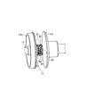
- FIG. 2 is a schematic view of the secondary pulley with the chain removed.
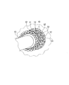
- FIG. 3 is a schematic perspective view of the output shaft portion of the secondary pulley.
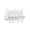
- FIG. 4 is a schematic cross-sectional view of the secondary pulley cut along the axial direction of the output shaft.
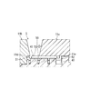
- FIG. 5 is a diagram showing a state in which the movable conical plate moves to the fixed conical plate side in FIG.
- FIG. 6 is a schematic configuration diagram of a spring.
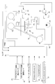
- FIG. 7 is a conceptual diagram of the hydraulic control unit and the CVT control unit of the first embodiment.
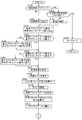
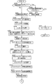
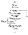
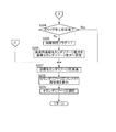
- FIG. 8 is a flowchart illustrating the shift control according to the first embodiment.
- FIG. 8 is a flowchart illustrating the shift control according to the first embodiment.
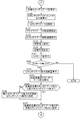
- FIG. 9 is a flowchart illustrating the shift control according to the first embodiment.
- FIG. 10 is a flowchart illustrating the shift control according to the first embodiment.
- FIG. 11 is a map showing the relationship between the shift difference thrust and the target line pressure.
- FIG. 12 is a map showing the relationship between the target line pressure and the line pressure solenoid command value.
- FIG. 13 is a map showing the relationship between the target primary pulley pressure and the primary pulley pressure solenoid command value.
- FIG. 14 is a map showing the relationship between the target secondary pulley pressure and the secondary pulley pressure solenoid command value.
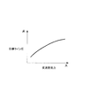
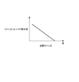
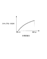
- FIG. 15 is a map showing the relationship between the stroke amount and the secondary pulley thrust reduction amount.
- FIG. 16 is a conceptual diagram of a hydraulic control unit and a CVT control unit according to the second embodiment.
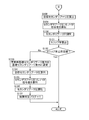
- FIG. 17 is a flowchart illustrating the shift control according to the second embodiment.
- FIG. 18 is a flowchart illustrating the shift control according to the second embodiment.
- FIG. 19 is a flowchart illustrating the shift control according to the second embodiment.
- FIG. 20 is a map showing the relationship between the target gear ratio and the step motor position.
- FIG. 21 is a flowchart illustrating the shift control according to the third embodiment.
- FIG. 22 is a flowchart illustrating the shift control according to the third embodiment.
- FIG. 23 is a flowchart illustrating the shift control according to the third embodiment.
- FIG. 24 is a map showing the relationship between the deviation and the secondary pulley pressure reduction amount.
- FIG. 1 is a schematic configuration diagram of a continuously variable transmission according to the first embodiment.
- the continuously variable transmission 5 is connected to the engine 1 via a torque converter 2 having a lock-up clutch and a forward / reverse switching mechanism 4.
- the continuously variable transmission 5 includes a primary pulley 10 to which driving force is transmitted from the engine 1, a secondary pulley 11 coupled to the output shaft 13, and an endless chain link that is wound around the primary pulley 10 and the secondary pulley 11. (Hereinafter referred to as a chain) 12.
- the output shaft 13 is connected to the differential 6 via an idler gear 14.
- the chain 12 is a band formed by connecting a large number of links with link pins to form an annular shape.
- a meshing groove 12 a that can mesh with a tooth portion 53 of a movable tooth 40 described later is formed on the inner peripheral surface of the chain 12.
- the meshing refers to a state in which the meshing groove 12 a and the tooth portion 53 overlap in the radial direction of the output shaft 13 and power is transmitted between the meshing groove 12 a and the tooth portion 53. Since the meshing groove 12 a meshes with the movable tooth 40, it is possible to suppress the occurrence of slip between the chain 12 and the secondary pulley 11.
- the primary pulley 10 includes a fixed conical plate 10b that rotates integrally with the input shaft, and a movable conical plate 10a that is disposed to face the fixed conical plate 10b and forms a V-shaped pulley groove.
- the movable conical plate 10a is displaced in the axial direction of the input shaft when primary pulley pressure is supplied to and discharged from the primary pulley cylinder chamber 10c.
- the secondary pulley 11 includes a fixed conical plate 11 b that rotates integrally with the output shaft 13, a movable conical plate 11 a that is disposed opposite to the fixed conical plate 11 b to form a V-shaped pulley groove, and a shaft of the output shaft 13.
- a movable tooth 40 formed along the direction and a spring 41 that urges the movable tooth 40 outward in the radial direction of the output shaft 13 are provided.
- FIG. 2 is a schematic view of the secondary pulley 11 with the chain 12 removed.
- FIG. 3 is a schematic perspective view of the output shaft 13 portion of the secondary pulley 11.
- FIG. 4 is a schematic cross-sectional view of the secondary pulley 11 cut along the axial direction of the output shaft 13.
- the movable tooth 40 is movable in the radial direction of the output shaft 13 in each of a plurality of movable tooth guide grooves 42 provided on the outer peripheral surface of the output shaft 13 at equal intervals in the circumferential direction and along the axial direction. It is provided as follows.
- the movable tooth 40 rotates integrally with the output shaft 13.
- the movable tooth 40 includes a base 50 extending in the axial direction of the output shaft 13, a first stopper 51 projecting radially outward from the end of the base 50 on the fixed conical plate 11 b side, and a movable cone in the base 50.
- a second stopper 52 projecting radially outward of the output shaft 13 from the end on the plate 11a side, and a tooth projecting radially outward of the output shaft 13 from the base 50 between the first stopper 51 and the second stopper 52 Part 53.
- the movable tooth 40 is pushed radially outward of the output shaft 13 by a spring 41 provided between the base 50 and the output shaft 13.
- the movable tooth 40 moves in the radial direction of the output shaft 13 according to the elastic force of the spring 41 and the pressing force generated when the meshing groove 12 a of the chain 12 meshes with the movable tooth 40.
- the first stopper 51 contacts the inner peripheral surface 11d of the fixed conical plate 11b
- the second stopper 52 is the inner peripheral surface of the movable conical plate 11a. 11e.
- the first stopper 51 contacts the inner peripheral surface 11d of the fixed conical plate 11b
- the second stopper 52 contacts the inner peripheral surface 11e of the movable conical plate 11a. Movement to the outside in the radial direction is restricted.
- the movable tooth 40 moves to the output shaft 13 side and is held at a position where the elastic force and the pressing force are balanced.
- the tooth portion 53 is formed along the axial direction of the output shaft 13 and is formed according to the shape of the meshing groove 12 a of the chain 12.
- the tooth tip of the tooth portion 53 is formed so as not to protrude outward in the radial direction of the output shaft 13 from the inner peripheral surfaces 11d and 11e. Therefore, the movable conical plate 11a can move in the axial direction of the output shaft 13 without interfering with the tooth portion 53, as shown in FIG.
- FIG. 5 is a diagram illustrating a state in which the movable conical plate 11a moves to the fixed conical plate 11b side in FIG.
- the spring 41 is configured by alternately arranging linear U-shaped elements 60 and linear connecting elements 61 on the same circumference.
- FIG. 6 is a schematic configuration diagram of the spring 41.
- the three springs 41 are arranged in the axial direction of the output shaft 13.
- the connecting element 61 engages with a groove 13a provided in the circumferential direction of the output shaft 13, and movement of the output shaft 13 inward in the radial direction is restricted by a groove bottom 13b.
- the U-shaped element 60 is provided such that a U-shaped bottom portion 60 a is located on the radially outer side of the output shaft 13 with respect to the connecting element 61, and the bottom portion 60 a contacts the movable tooth 40.
- the elastic force of the spring 41 increases as the movable tooth 40 is pushed radially inward of the output shaft 13.
- the U-shaped elements 60 are provided in the same number as the movable teeth 40, and the elastic force that each movable tooth 40 receives from the U-shaped elements 60 varies depending on the contact state between each movable tooth 40 and the chain 12.
- the movable conical plate 11a is displaced in the axial direction of the output shaft 13 when the secondary pulley pressure is supplied to and discharged from the secondary pulley cylinder chamber 11c.
- the continuously variable transmission 5 changes speed by changing the balance between the primary pulley pressure and the secondary pulley pressure.
- the gear ratio of the continuously variable transmission 5 and the thrust of the pulleys 10 and 11 are controlled by a hydraulic control unit 100 that responds to a command from the CVT control unit 20.
- the CVT control unit 20 determines and controls the target gear ratio and thrust based on engine output torque information output from the engine control unit 21 that controls the engine 1 and signals output from sensors and the like described later.
- the driving torque generated in the engine 1 is input to the primary pulley 10 of the continuously variable transmission 5 via the torque converter 2 and the forward / reverse switching mechanism 4 and is transmitted from the primary pulley 10 to the secondary pulley 11 via the chain 12. .
- the primary pulley 10 and the movable conical plate 11a of the secondary pulley 11 are changed. And the gear ratio in the secondary pulley 11 is continuously changed.
- the hydraulic control unit 100 includes a regulator valve 32 that controls the line pressure, a pressure reducing valve 30 that controls the primary pulley pressure, and a pressure reducing valve 34 that controls the secondary pulley pressure.
- FIG. 7 is a conceptual diagram of the hydraulic control unit 100 and the CVT control unit 20 in the first embodiment.
- the regulator valve 32 includes a solenoid 33 that regulates the pressure of oil discharged from an oil pump 36 that is driven by transmission of part of the driving torque generated in the engine 1.
- the regulator valve 32 adjusts the pressure of the oil discharged from the oil pump 36 to a predetermined line pressure corresponding to the operating state in accordance with a command (for example, a duty signal) from the CVT control unit 20.
- the pressure reducing valve 30 includes a solenoid 31 that regulates the line pressure.
- the pressure reducing valve 30 adjusts the line pressure to a predetermined primary pulley pressure in accordance with a command (for example, a duty signal) from the CVT control unit 20.
- the primary pulley pressure is supplied to and discharged from the primary pulley cylinder chamber 10c.
- the pressure reducing valve 34 includes a solenoid 35 that regulates the line pressure.
- the pressure reducing valve 34 adjusts the line pressure to a predetermined secondary pulley pressure in accordance with a command (for example, a duty signal) from the CVT control unit 20.
- the secondary pulley pressure is supplied to and discharged from the secondary pulley cylinder chamber 11c.
- the CVT control unit 20 includes a signal from the inhibitor switch 22, a signal from the accelerator pedal sensor 23, a signal from the primary pulley rotational speed sensor 24, a signal from the secondary pulley rotational speed sensor 25, a signal from the brake pedal sensor 26, the engine Based on the signal from the control unit 21, the gear ratio and the like are controlled. From the engine control unit 21, information on the engine rotation speed, the output torque of the engine 1, and the like is sent based on the signal from the engine rotation speed sensor 29.
- the speed change control of the present embodiment facilitates the change to the speed change ratio in which the meshing groove 12a of the chain 12 meshes with the movable tooth 40 by adjusting the secondary pulley pressure in the above situation.
- step S100 the CVT control unit 20 determines whether or not a failure determination flag described later in detail is “1”. The process proceeds to step S138 when the failure determination flag is “1”, and proceeds to step S101 when the failure determination flag is “0”.
- step S101 the CVT control unit 20 calculates the target gear ratio from the shift line map based on the input torque, the throttle opening, the vehicle speed, and the position of the select lever.
- the throttle opening is detected based on a signal from the accelerator pedal sensor 23.
- the vehicle speed is detected based on a signal from a wheel speed sensor (not shown).
- the position of the selector lever is detected based on a signal from the inhibitor switch 22.
- step S102 the CVT control unit 20 calculates a basic primary pulley thrust and a basic secondary pulley thrust based on the target gear ratio.
- the basic primary pulley thrust and the basic secondary pulley thrust are thrusts obtained by adding a safety allowance to the minimum thrust limit value necessary to realize the target gear ratio.
- step S103 the CVT control unit 20 determines whether the basic primary pulley thrust is equal to or greater than the minimum primary pulley thrust. The process proceeds to step S105 when the basic primary pulley thrust is greater than or equal to the minimum primary pulley thrust, and proceeds to step S104 when the basic primary pulley thrust is smaller than the minimum primary pulley thrust.
- step S104 the CVT control unit 20 sets the minimum primary pulley thrust to the basic primary pulley thrust.
- step S105 the CVT control unit 20 determines whether the basic secondary pulley thrust is equal to or greater than the minimum secondary pulley thrust. The process proceeds to step S107 when the basic secondary pulley thrust is greater than or equal to the minimum secondary pulley thrust, and proceeds to step S106 when the basic secondary pulley thrust is smaller than the minimum secondary pulley thrust.
- step S106 the CVT control unit 20 sets the minimum secondary pulley thrust to the basic secondary pulley thrust.
- step S107 the CVT control unit 20 calculates a shift difference thrust based on the basic primary pulley thrust and the basic secondary pulley thrust.
- step S108 the CVT control unit 20 calculates the target line pressure from the shift difference thrust map shown in FIG. 11 based on the shift difference thrust.
- step S109 the CVT control unit 20 calculates a line pressure solenoid command value from the map shown in FIG. 12 based on the target line pressure.
- step S110 the CVT control unit 20 controls the solenoid 33 of the regulator valve 32 based on the line pressure solenoid command value to adjust the line pressure.
- step S111 the CVT control unit 20 calculates a target primary pulley pressure based on the basic primary pulley thrust.
- step S112 the CVT control unit 20 calculates a primary pulley pressure solenoid command value from the map shown in FIG. 13 based on the target primary pulley pressure.
- step S113 the CVT control unit 20 controls the solenoid 31 of the pressure reducing valve 30 based on the primary pulley pressure solenoid command value to adjust the primary pulley pressure.
- step S114 the CVT control unit 20 calculates a target secondary pulley pressure based on the basic secondary pulley thrust.
- step S115 the CVT control unit 20 calculates a secondary pulley pressure solenoid command value from the map shown in FIG. 14 based on the target secondary pulley pressure.
- step S116 the CVT control unit 20 controls the solenoid 35 of the pressure reducing valve 34 based on the secondary pulley pressure solenoid command value to adjust the secondary pulley pressure.
- step S117 the CVT control unit 20 detects the primary pulley rotation speed based on the signal from the primary pulley rotation speed sensor 24.
- step S118 the CVT control unit 20 detects the secondary pulley rotational speed based on the signal from the secondary pulley rotational speed sensor 25.
- step S119 the CVT control unit 20 calculates the actual gear ratio by dividing the primary pulley rotational speed by the secondary pulley rotational speed.
- step S120 the CVT control unit 20 calculates the contact radius between the secondary pulley 11 and the chain 12 based on the actual gear ratio and the secondary pulley rotation speed.
- step S121 the CVT control unit 20 calculates the stroke amount of the movable tooth 40.
- the CVT control unit 20 is the contact radius between the secondary pulley 11 and the chain 12 when the meshing groove 12a of the chain 12 reaches the first gear ratio (predetermined gear ratio) that meshes with the movable teeth 40.
- a deviation between the predetermined radius and the contact radius between the secondary pulley 11 and the chain 12 calculated in step S120 is calculated.
- the stroke amount is zero or more when the meshing groove 12a of the chain 12 and the movable tooth 40 are meshed, and is smaller than zero when the meshing groove 12a of the chain 12 and the movable tooth 40 are not meshed. Become.
- step S122 the CVT control unit 20 determines whether or not the stroke amount is zero or more. The process ends the control when the stroke amount is smaller than zero, and proceeds to step S123 when the stroke amount is zero or more.
- the elastic force of the spring 41 acts on the chain 12 on the secondary pulley 11 side in addition to the clamping force by the hydraulic pressure supplied to the secondary pulley cylinder chamber 11c.
- the elastic force by the spring 41 is a force that prevents shifting to the High side.
- the elastic force by the spring 41 increases as the stroke amount increases.
- step S123 the CVT control unit 20 calculates the secondary pulley thrust reduction amount from the map shown in FIG. 15 based on the stroke amount.
- the secondary pulley thrust reduction amount increases as the stroke amount increases, and is calculated so as to reduce the tension of the chain 12 that increases on the secondary pulley 11 side by the elastic force of the spring 41.
- step S124 the CVT control unit 20 subtracts the secondary pulley thrust reduction amount from the basic secondary pulley thrust to calculate a reduced basic secondary pulley thrust.
- step S125 the CVT control unit 20 determines whether the post-reduction basic secondary pulley thrust is equal to or greater than the minimum secondary pulley thrust. The process proceeds to step S127 when the reduced basic secondary pulley thrust is equal to or greater than the minimum secondary pulley thrust, and proceeds to step S126 when the reduced basic secondary pulley thrust is smaller than the minimum secondary pulley thrust.
- step S126 the CVT control unit 20 sets the minimum secondary pulley thrust as the reduced basic secondary pulley thrust.
- step S127 the CVT control unit 20 sets the reduced basic secondary pulley thrust as the basic secondary pulley thrust.
- the current basic secondary pulley thrust is overwritten with the reduced basic secondary pulley thrust.
- step S1208 the CVT control unit 20 calculates the target secondary pulley pressure based on the basic secondary pulley thrust set in step S127.
- step S129 the CVT control unit 20 calculates the secondary pulley pressure solenoid command value from the map shown in FIG. 14 based on the target secondary pulley pressure.
- step S130 the CVT control unit 20 controls the solenoid 35 of the pressure reducing valve 34 based on the secondary pulley pressure solenoid command value to adjust the secondary pulley pressure.
- the basic secondary pulley thrust is overwritten in step S128, the secondary pulley pressure is adjusted again according to the value.
- step S131 the CVT control unit 20 calculates a slip ratio based on the actual gear ratio and the target gear ratio.
- the slip ratio is a deviation between the actual gear ratio and the target gear ratio.
- step S132 the CVT control unit 20 determines whether the slip ratio is equal to or less than a predetermined value.
- the predetermined value is a value for determining whether or not the meshing groove 12a of the chain 12 and the movable tooth 40 are meshed, and is set in advance by an experiment or the like. For example, when it is determined in step S122 that the stroke amount is zero or more and the engagement groove 12a of the chain 12 and the movable tooth 40 are engaged, the slip ratio is greater than a predetermined value. There is a possibility that an abnormality occurs in at least one of the movable teeth 40, the spring 41, and the chain 12, and the engagement groove 12a of the chain 12 and the movable teeth 40 may not be engaged.
- step S132 the CVT control unit 20 determines that an abnormality has occurred in at least one of the movable teeth 40, the spring 41, and the chain 12 when the slip ratio is greater than a predetermined value. The process ends this control when the slip ratio is equal to or less than the predetermined value, and proceeds to step S133 when the slip ratio is larger than the predetermined value.
- step S133 the CVT control unit 20 applies an abnormality when an abnormality occurs in at least one of the movable teeth 40, the spring 41, and the chain 12, and the engagement groove 12a of the chain 12 and the movable teeth 40 are not engaged.
- Hour basic secondary pulley thrust is set as basic secondary pulley thrust.
- the basic secondary pulley thrust set in step S127 is further overwritten.
- step S134 the CVT control unit 20 calculates the target secondary pulley pressure based on the basic secondary pulley thrust.
- step S135 the CVT control unit 20 calculates a secondary pulley pressure solenoid command value from the map shown in FIG. 14 based on the target secondary pulley pressure.
- step S136 the CVT control unit 20 controls the solenoid 35 of the pressure reducing valve 34 based on the secondary pulley pressure solenoid command value to adjust the secondary pulley pressure.
- the secondary pulley pressure is adjusted again according to the value.
- step S137 the CVT control unit 20 sets the failure determination flag to “1”.
- the failure determination flag is set to “0” as an initial value.
- step S138 the CVT control unit 20 determines that the other abnormality determination flag, for example, the gear ratio is the meshing groove 12a of the chain 12 and the movable teeth 40. Whether or not an abnormality has occurred in the continuously variable transmission 5 is determined based on a flag indicating that slip has occurred at a gear ratio that is lower than the first gear ratio. The process proceeds to step S139 if another abnormality has occurred in the continuously variable transmission 5, and proceeds to step S140 if no other abnormality has occurred in the continuously variable transmission 5.
- the other abnormality determination flag for example, the gear ratio is the meshing groove 12a of the chain 12 and the movable teeth 40.
- step S139 the CVT control unit 20 executes the safe mode.
- the safe mode for example, when the vehicle is traveling, the gear ratio is maintained at the current gear ratio, and after the vehicle stops, the gear ratio is limited to the lowest level.
- step S140 the CVT control unit 20 limits the gear ratio so that the meshing groove 12a of the chain 12 and the movable tooth 40 do not mesh. Further, the CVT control unit 20 notifies the driver by turning on a warning lamp indicating that any one of the movable teeth 40, the spring 41, and the chain 12 is abnormal.
- the movable tooth 40 It is determined that an abnormality has occurred in at least one of the spring 41 and the chain 12. Thereby, abnormality generation of the movable tooth 40, the spring 41, and the chain 12 can be detected, and a state where the meshing groove 12a and the movable tooth 40 are not normally meshed can be detected.
- the actual gear ratio becomes the first gear ratio in which the meshing groove 12a of the chain 12 meshes with the movable teeth 40, and after the stroke amount becomes zero or more, the slip ratio between the actual gear ratio and the target gear ratio is larger than a predetermined value. If it is determined that the engagement groove 12a of the chain 12 is not engaged with the movable tooth 40, it is determined that an abnormality has occurred in at least one of the movable tooth 40, the spring 41, and the chain 12. Thereby, it is possible to detect the occurrence of an abnormality in the movable tooth 40, the spring 41, and the chain 12 without using a hydraulic sensor.
- the gear ratio is limited to a gear ratio at which the meshing groove 12a of the chain 12 and the movable teeth 40 do not mesh. Thereby, it can suppress that the state of the movable tooth 40 in which abnormality generate
- a warning light is turned on. As a result, it is possible to notify the driver that an abnormality has occurred.
- FIG. 16 is a conceptual diagram of the hydraulic control unit 100 and the CVT control unit 20.
- symbol of 1st Embodiment is attached
- subjected and description here is abbreviate
- the hydraulic control unit 100 includes a regulator valve 32, a shift control valve 37, a pressure reducing valve 30, and a pressure reducing valve 34.
- the shift control valve 37 is a control valve that controls the primary pulley pressure in the primary pulley cylinder chamber 10c to a desired target pressure.
- the shift control valve 37 is connected to a servo link 70 constituting a mechanical feedback mechanism, is driven by a step motor 71 connected to one end of the servo link 70, and is connected to the other end of the servo link 70.
- the groove width that is, feedback of the actual gear ratio is received from the movable conical plate 10a.
- the speed change control valve 37 adjusts the primary pulley pressure so as to achieve the target speed ratio commanded at the drive position of the step motor 71 by sucking and discharging the hydraulic pressure to the primary pulley cylinder chamber 10c by the displacement of the spool 37a.
- the spool 37a is held in the valve closing position in response to the displacement from the servo link 70.
- the CVT control unit 20 includes a signal from the inhibitor switch 22, a signal from the accelerator pedal sensor 23, a signal from the primary pulley rotational speed sensor 24, a signal from the secondary pulley rotational speed sensor 25, a signal from the brake pedal sensor 26, a primary Based on the signal from the pulley pressure sensor 27, the signal from the secondary pulley pressure sensor 28, etc., the gear ratio and the like are controlled.
- step S200 the CVT control unit 20 determines whether or not the failure determination flag is “1”. The process proceeds to step S230 when the failure determination flag is “1”, and proceeds to step S201 when the failure determination flag is “0”.
- step S201 the CVT control unit 20 calculates the target gear ratio from the vehicle speed, the engine rotation speed, the throttle opening, and the position of the select lever.
- the engine speed is detected based on a signal from the engine speed sensor 29.
- step S202 the CVT control unit 20 calculates the step motor position from the map shown in FIG. 20 based on the target gear ratio.
- step S203 the CVT control unit 20 drives the step motor 71 based on the calculated step motor position. Thereby, the shift control valve 37 is controlled.
- step S204 the CVT control unit 20 receives input torque information from the engine control unit 21.
- step S205 the CVT control unit 20 calculates the minimum thrust limit value, the basic primary pulley thrust, and the basic secondary pulley thrust based on the target gear ratio and the input torque.
- step S206 the CVT control unit 20 calculates the target line pressure based on the basic primary pulley thrust and the basic secondary pulley thrust.
- step S207 the CVT control unit 20 calculates a line pressure solenoid command value from the map shown in FIG. 12 based on the target line pressure.
- step S208 the CVT control unit 20 controls the solenoid 33 of the regulator valve 32 based on the line pressure solenoid command value to adjust the line pressure.
- step S209 the CVT control unit 20 calculates the target primary pulley pressure and the target secondary pulley pressure by thrust distribution control based on the basic secondary pulley thrust and the minimum thrust limit value.
- step S210 the CVT control unit 20 calculates a primary pulley pressure solenoid command value from the map shown in FIG. 13 based on the target primary pulley pressure.
- step S211 the CVT control unit 20 controls the solenoid 31 of the pressure reducing valve 30 based on the primary pulley pressure solenoid command value to adjust the primary pulley pressure supplied to the shift control valve 37.
- step S212 the CVT control unit 20 detects the primary pulley rotation speed based on the signal from the primary pulley rotation speed sensor 24.
- step S213 the CVT control unit 20 detects the secondary pulley rotational speed based on the signal from the secondary pulley rotational speed sensor 25.
- step S214 the CVT control unit 20 calculates the actual gear ratio by dividing the primary pulley rotational speed by the secondary pulley rotational speed.
- step S215 the CVT control unit 20 calculates the contact radius between the secondary pulley 11 and the chain 12 based on the actual gear ratio and the secondary pulley rotational speed.
- step S216 the CVT control unit 20 calculates the stroke amount of the movable tooth 40.
- the method for calculating the stroke amount is the same as that in step S121 in the first embodiment.
- step S217 the CVT control unit 20 determines whether or not the stroke amount is zero or more. The process proceeds to step S227 when the stroke amount is smaller than zero, and proceeds to step S218 when the stroke amount is zero or more.
- step S218 the CVT control unit 20 calculates the secondary pulley thrust reduction amount from the map shown in FIG. 15 based on the stroke amount.
- step S219 the CVT control unit 20 subtracts the secondary pulley thrust reduction amount from the basic secondary pulley thrust to calculate a reduced basic secondary pulley thrust.
- step S220 the CVT control unit 20 determines whether or not the reduced basic secondary pulley thrust is equal to or greater than the minimum secondary pulley thrust. The process proceeds to step S222 when the reduced basic secondary pulley thrust is equal to or greater than the minimum secondary pulley thrust, and proceeds to step S221 when the reduced basic secondary pulley thrust is smaller than the minimum secondary pulley thrust.
- step S221 the CVT control unit 20 sets the minimum secondary pulley thrust as the reduced basic secondary pulley thrust.
- step S222 the CVT control unit 20 sets the reduced basic secondary pulley thrust as the basic secondary pulley thrust.
- the basic secondary pulley thrust calculated in step S205 is overwritten.
- step S223 the CVT control unit 20 calculates the slip ratio based on the actual gear ratio and the target gear ratio.
- the calculation method of the slip ratio is the same method as step S131 of the first embodiment.
- step S224 the CVT control unit 20 determines whether the slip rate is equal to or less than a predetermined value. The process proceeds to step S227 when the slip ratio is equal to or less than the predetermined value, and proceeds to step S225 when the slip ratio is larger than the predetermined value.
- step S225 the CVT control unit 20 sets the failure determination flag to “1”.
- step S226 the CVT control unit 20 applies an abnormality when an abnormality occurs in at least one of the movable teeth 40, the spring 41, and the chain 12, and the engagement groove 12a of the chain 12 and the movable teeth 40 are not engaged.
- Hour basic secondary pulley thrust is set as basic secondary pulley thrust.
- the basic secondary pulley thrust set in step S222 is further overwritten.
- step S227 the CVT control unit 20 calculates a target secondary pulley pressure. Specifically, when the stroke amount is smaller than zero in step S217, the CVT control unit 20 sets the target secondary pulley pressure calculated in step S209 as it is as the target secondary pulley pressure. When it is determined in step S224 that the slip ratio is equal to or less than the predetermined value, the CVT control unit 20 calculates the target secondary pulley pressure based on the basic secondary pulley thrust set in step S222. Further, when it is determined in step S224 that the slip ratio is larger than the predetermined value, the CVT control unit 20 calculates the target secondary pulley pressure based on the basic secondary pulley thrust set in step S226.
- step S2208 the CVT control unit 20 calculates the secondary pulley pressure solenoid command value from the map shown in FIG. 14 based on the target secondary pulley pressure.
- step S229 the CVT control unit 20 controls the solenoid 35 of the pressure reducing valve 34 based on the secondary pulley pressure solenoid command value to adjust the secondary pulley pressure.
- step S200 The control after step S200 is determined that the failure determination flag is “1” is the same as the control of step S138 to step S140 in the first embodiment, and therefore will be described here. Is omitted.
- the third embodiment differs from the second embodiment in shift control. Shift control in the present embodiment will be described with reference to FIGS.
- step S300 to step S311 Since the control from step S300 to step S311 is the same as the control from step S200 to step S211 of the second embodiment, description thereof is omitted here.
- step S312 the CVT control unit 20 detects the actual primary pulley pressure based on the signal from the primary pulley pressure sensor 27.
- step S313 the CVT control unit 20 determines whether the actual primary pulley pressure is equal to the target primary pulley pressure. The process proceeds to step S323 when the actual primary pulley pressure and the target primary pulley pressure are equal, and proceeds to step S314 when the actual primary pulley pressure and the target primary pulley pressure are not equal.
- step S314 the CVT control unit 20 determines whether the actual primary pulley pressure is lower than the target primary pulley pressure. The process proceeds to step S315 when the actual primary pulley pressure is higher than the target primary pulley pressure, and proceeds to step S323 when the actual primary pulley pressure is lower than the target primary pulley pressure.
- step S315 the CVT control unit 20 detects the primary pulley rotation speed based on the signal from the primary pulley rotation speed sensor 24.
- step S316 the CVT control unit 20 detects the secondary pulley rotational speed based on the signal from the secondary pulley rotational speed sensor 25.
- step S317 the CVT control unit 20 calculates the actual gear ratio by dividing the primary pulley rotational speed by the secondary pulley rotational speed.
- step S3108 the CVT control unit 20 determines whether or not the actual speed ratio is equal to or less than the second speed ratio (predetermined speed ratio).
- the second gear ratio is a gear ratio at which it can be determined that the meshing groove 12a of the chain 12 meshes with the movable tooth 40 and the actual primary pulley pressure is equal to or higher than a predetermined hydraulic pressure.
- the predetermined hydraulic pressure is a pressure at which it can be determined that the chain 12 is urged radially outward of the output shaft 13 by the elastic force of the spring 41, and is set in consideration of an error of a sensor or the like, and as the input torque increases. growing.
- the predetermined oil pressure is a pressure that is 110% higher than the target primary pulley pressure.
- step S319 the CVT control unit 20 determines whether the actual primary pulley pressure is equal to or higher than a predetermined hydraulic pressure.
- the predetermined hydraulic pressure is the same value as the predetermined hydraulic pressure in step S318.
- the process proceeds to step S320 when the actual primary pulley pressure is equal to or higher than the predetermined oil pressure, and proceeds to step S321 when the actual primary pulley pressure is lower than the predetermined oil pressure.
- step S320 the CVT control unit 20 sets the secondary pulley reduction instruction flag to “1”.
- the secondary pulley reduction instruction flag is set to “0” as an initial value.
- step S321 the CVT control unit 20 determines whether or not the secondary pulley reduction instruction flag is “1”. The process proceeds to step S324 if the secondary pulley reduction instruction flag is “1”, and proceeds to step S322 if the secondary pulley reduction instruction flag is “0”.
- step S322 the CVT control unit 20 sets the failure determination flag to “1”.
- the failure determination flag is set to “0” as an initial value.
- step S323 the CVT control unit 20 determines whether the secondary pulley reduction instruction flag is “1”. The process proceeds to step S324 when the secondary pulley reduction instruction flag is “1”, and proceeds to step S336 when the secondary pulley reduction instruction flag is “0”.
- step S324 the CVT control unit 20 determines whether or not the secondary pulley pressure reduction learning flag for the input torque described later in detail is “1”. The process proceeds to step S325 when the secondary pulley pressure reduction learning flag is “1”, and proceeds to step S326 when the secondary pulley pressure reduction learning flag is “0”.
- step S325 the CVT control unit 20 sets a learning value, which will be described in detail later, as a target secondary pulley pressure based on the actual gear ratio.
- the current target secondary pulley pressure is overwritten by the learned value.
- step S326 the CVT control unit 20 calculates the deviation between the actual primary pulley pressure and the target primary pulley pressure.
- step S327 the CVT control unit 20 calculates the secondary pulley pressure reduction amount from the map shown in FIG. 24 based on the deviation.
- the amount of secondary pulley pressure reduction increases as the deviation increases.
- the secondary pulley pressure reduction amount is calculated so as to reduce the tension of the chain 12 that increases on the secondary pulley 11 side by the elastic force of the spring 41. Thereby, even when the meshing groove 12a of the chain 12 meshes with the movable tooth 40, it becomes possible to perform a shift without increasing the primary pulley pressure.
- step S328 the CVT control unit 20 subtracts the secondary pulley pressure reduction amount from the target secondary pulley pressure, and calculates the post-reduction secondary pulley pressure.
- step S329 the CVT control unit 20 calculates the minimum secondary pulley pressure based on the basic secondary pulley thrust and the minimum thrust limit value.
- step S330 the CVT control unit 20 determines whether the post-reduction secondary pulley pressure is equal to or greater than the minimum secondary pulley pressure. The process proceeds to step S331 when the post-reduction secondary pulley pressure is greater than or equal to the minimum secondary pulley pressure, and proceeds to step S332 when the post-reduction secondary pulley pressure is lower than the minimum secondary pulley pressure.
- step S331 the CVT control unit 20 sets the post-reduction secondary pulley pressure as the target secondary pulley pressure.
- the current target secondary pulley pressure is overwritten by the post-reduction secondary pulley pressure.
- step S332 the CVT control unit 20 sets the minimum secondary pulley pressure command value as the target secondary pulley pressure.
- the current target secondary pulley pressure is overwritten by the minimum secondary pulley pressure command value.
- step S331 and S332 is temporarily stored in the CVT control unit 20 in accordance with each actual gear ratio.
- step S333 the CVT control unit 20 determines whether or not the actual gear ratio is the highest. The process proceeds to step S334 when the actual gear ratio is the highest, and proceeds to step S336 when the actual gear ratio is not the highest.
- step S334 the CVT control unit 20 stores the target secondary pulley pressure stored for the actual gear ratio as a learning value. Note that the temporarily stored target secondary pulley pressure is deleted. Further, the target secondary pulley pressure that is temporarily stored is also deleted when the actual gear ratio is changed from the previous control to the low gear ratio.
- step S335 the CVT control unit 20 sets the secondary pulley pressure learning flag to “1”.
- the secondary pulley pressure learning flag is set to “0” as an initial value.
- the secondary pulley pressure learning flag is set for each input torque.
- step S336 the CVT control unit 20 calculates the secondary pulley pressure solenoid command value from the map shown in FIG. 14 based on the target secondary pulley pressure.
- step S337 the CVT control unit 20 controls the solenoid 35 of the pressure reducing valve 34 based on the secondary pulley pressure solenoid command value to adjust the secondary pulley pressure.
- control after steps S 338 to S 340 which is the control after it is determined that the failure determination flag is “1” in step S 300, is the same as the control of steps S 138 to S 140 in the first embodiment, and will be described here. Is omitted.
- the actual transmission gear ratio becomes the second transmission gear ratio in which the meshing groove 12a of the chain 12 meshes with the movable tooth 40
- the actual primary pulley pressure is greater than the predetermined hydraulic pressure when the meshing groove 12a of the chain 12 meshes with the movable tooth 40.
- it is low it is determined that the meshing groove 12 a of the chain 12 is not meshed with the movable tooth 40.
- the secondary pulley thrust reduction amount is calculated and the secondary pulley pressure is lowered.
- the secondary pulley thrust reduction amount may be calculated to lower the secondary pulley pressure.
- an abnormality occurs in at least one of the movable teeth 40, the spring 41, or the chain 12 based on the slip ratio or the primary pulley pressure, and the engagement groove 12a of the chain 12 and the movable teeth 40 are not engaged.
- it may be determined based on hydraulic pressure, oil vibration, sound, or the like.
- the engine 1 is used as a power source, but a motor or an engine and a motor may be used as the power source.
- the chain 12 is used as the power transmission part (band body) of the continuously variable transmission 5.
- a power transmission part that transmits power on the pull side for example, a rubber belt that can mesh with the movable teeth 40, may be used. Good.
- the movable teeth 40 are provided on the secondary pulley 11, but the movable teeth 40 may be provided on the primary pulley 10.
- the gear ratio is limited when any one of the movable teeth 40, the spring 41, and the chain 12 is abnormal.
- the pulley pressure may not be lowered. Thereby, it is possible to suppress slippage between the chain 12 and the secondary pulley 11.
Landscapes
- Engineering & Computer Science (AREA)
- General Engineering & Computer Science (AREA)
- Mechanical Engineering (AREA)
- Control Of Transmission Device (AREA)
- Transmissions By Endless Flexible Members (AREA)
Abstract
可動歯に噛合可能な溝が形成された帯体と、帯体を軸部の径方向外側に付勢する付勢部とを備える無段変速機であって、溝が可動歯に噛合するかどうか判定する噛合判定部と、変速比が、溝が可動歯に噛合する所定変速比となり、かつ噛合判定部によって溝が可動歯に噛合していないと判定された場合には、可動歯、付勢部、帯体の少なくともいずれか一つに異常が発生していると判定する異常判定部とを備える。
Description
本発明は無段変速機に関するものである。
従来、バネによって径方向外側に付勢される可動歯をプーリの軸部に設け、無終端チェーンリンクに噛合溝を設け、変速比が例えば最High変速比となる場合に噛合溝を可動歯に噛合させる無段変速機がJP2010-014269Aに開示されている。
上記の無段変速機では、可動歯、バネなどが破損するなどにより機能していない場合には、噛合溝が可動歯に噛合せず、無終端チェーンリンクとプーリとの間で滑りが発生してしまうので、噛合溝と可動歯とが正常に噛合しているか否かを検知する必要がある。
本発明はこのような点に鑑みて発明されたもので、噛合溝と可動歯とが正常に噛合しているか否かを検知することを目的とする。
本発明のある態様に係る無段変速機は、第1固定円錐板と、第1油室に給排される油圧に応じて軸方向に移動する第1可動円錐板とを有する第1プーリと、第2固定円錐板と、第2油室に給排される油圧に応じて軸方向に移動する第2可動円錐板と、軸部の径方向に移動可能な可動歯とを有する第2プーリと、第1プーリと第2プーリとの間に巻き掛けられて第1プーリと第2プーリとの間で動力を伝達し、可動歯に噛合可能な溝が内周面に形成された環状の帯体と、可動歯を軸部の径方向外側に付勢する付勢部とを備える無段変速機であって、溝が可動歯に噛合するかどうか判定する噛合判定部と、変速比が、溝が可動歯に噛合する所定変速比となり、かつ噛合判定部によって溝が可動歯に噛合していないと判定された場合には、可動歯、付勢部、帯体の少なくともいずれか一つに異常が発生していると判定する異常判定部とを備える。
本発明の別の態様に係る制御方法は、第1固定円錐板と、第1油室に給排される油圧に応じて軸方向に移動する第1可動円錐板とを有する第1プーリと、第2固定円錐板と、第2油室に給排される油圧に応じて軸方向に移動する第2可動円錐板と、軸部の径方向に移動可能な可動歯とを有する第2プーリと、第1プーリと第2プーリとの間に巻き掛けられて第1プーリと第2プーリとの間で動力を伝達し、可動歯に噛合可能な溝が内周面に形成された環状の帯体と、可動歯を軸部の径方向外側に付勢する付勢部とを備える無段変速機を制御する制御方法であって、溝が可動歯に噛合するかどうか判定し、変速比が、溝が可動歯に噛合する所定変速比となり、かつ溝が可動歯に噛合していないと判定された場合には、可動歯、付勢部、帯体の少なくともいずれか一つに異常が発生していると判定する。
これらの態様によると、変速比が、帯体に設けた溝が可動歯に噛合する所定変速比となったにもかかわらず、溝が可動歯に噛合していないと判定されると、可動歯、付勢部、帯体の少なくともいずれか一つに異常が発生していると判定することで、溝と可動歯とが正常に噛合していない状態を検知することができる。
以下、本発明の実施形態を添付図面に基づいて説明する。なお、以下の説明において、「変速比」は、チェーン式無段変速機(以下、無段変速機と言う。)の入力回転速度を出力回転速度で割って得られる値である。無段変速機は変速比が小さいほどHigh側となる。図1は第1実施形態における無段変速機の概略構成図である。
無段変速機5はロックアップクラッチを備えたトルクコンバータ2、前後進切り替え機構4を介してエンジン1に連結される。無段変速機5は、エンジン1から駆動力が伝達されるプライマリプーリ10と、出力軸13に連結されたセカンダリプーリ11と、プライマリプーリ10とセカンダリプーリ11とに掛け回された無終端チェーンリンク(以下、チェーンと言う。)12とを備える。出力軸13はアイドラギア14を介してディファレンシャル6に連結される。
チェーン12は、多数のリンクをリンクピンで連結し、環状に形成される帯体である。チェーン12の内周面には、図4に示すように後述する可動歯40の歯部53が噛合可能な噛合溝12aが形成される。噛合とは、噛合溝12aと歯部53とが出力軸13の径方向において重なり、噛合溝12aと歯部53との間で動力伝達される状態を言う。噛合溝12aが可動歯40に噛合することで、チェーン12とセカンダリプーリ11との間で滑りが発生することを抑制することができる。
プライマリプーリ10は、入力軸と一体となって回転する固定円錐板10bと、固定円錐板10bに対向配置されてV字状のプーリ溝を形成する可動円錐板10aとを備える。可動円錐板10aは、プライマリプーリシリンダ室10cにプライマリプーリ圧が給排されることで入力軸の軸方向へ変位する。
セカンダリプーリ11は、出力軸13と一体となって回転する固定円錐板11bと、固定円錐板11bに対向配置されてV字状のプーリ溝を形成する可動円錐板11aと、出力軸13の軸方向に沿って形成される可動歯40と、可動歯40を出力軸13の径方向外側に付勢するバネ41とを備える。セカンダリプーリ11について図2~図4を用いて詳しく説明する。図2は、チェーン12を外したセカンダリプーリ11の概略図である。図3は、セカンダリプーリ11の出力軸13部分の概略斜視図である。図4は、セカンダリプーリ11を出力軸13の軸方向に沿って切断した概略断面図である。
可動歯40は、出力軸13の外周面にその周方向に等間隔で且つ軸方向に沿って設けられた複数の可動歯ガイド溝42の各々に、出力軸13の径方向へ移動可能となるように設けられる。可動歯40は出力軸13と一体となって回転する。
可動歯40は、出力軸13の軸方向に延びる基部50と、基部50における固定円錐板11b側の端部から出力軸13の径方向外側に突出する第1ストッパー51と、基部50における可動円錐板11a側の端部から出力軸13の径方向外側に突出する第2ストッパー52と、第1ストッパー51と第2ストッパー52との間の基部50から出力軸13の径方向外側に突出する歯部53とを備える。
可動歯40は、基部50と出力軸13との間に設けたバネ41によって、出力軸13の径方向外側に押されている。可動歯40は、バネ41による弾性力と、チェーン12の噛合溝12aが可動歯40に噛合する場合に発生する押力とに応じて出力軸13の径方向に移動する。押力がない場合、または弾性力が押力よりも大きい場合には、第1ストッパー51が固定円錐板11bの内周面11dに当接し、第2ストッパー52が可動円錐板11aの内周面11eに当接する。このように、第1ストッパー51が固定円錐板11bの内周面11dに当接し、第2ストッパー52が可動円錐板11aの内周面11eに当接することで、可動歯40は、出力軸13の径方向外側への移動が規制されている。押力が弾性力よりも大きい場合には、可動歯40は出力軸13側に移動し、弾性力と押力とが釣り合う位置に保持される。
歯部53は、出力軸13の軸方向に沿って形成され、チェーン12の噛合溝12aの形状に合わせて形成される。歯部53の歯先は、前記内周面11d、11eよりも出力軸13の径方向外側へ突出しないように形成されている。そのため、可動円錐板11aは、図5に示すように、歯部53に干渉することなく、出力軸13の軸方向へ移動可能となる。図5は、図4において可動円錐板11aが固定円錐板11b側に移動する状態を示す図である。
バネ41は、図6に示すように、線状のU字形エレメント60と、線状の連結エレメント61とを交互に同一円周上に配置して構成される。図6は、バネ41の概略構成図である。本実施形態では、図4に示すように3本のバネ41を出力軸13の軸方向に並べて配置する。
連結エレメント61は、出力軸13の周方向へ設けた溝13aに係合し、溝底13bによって出力軸13の径方向内側への移動が規制されている。
U字形エレメント60は、連結エレメント61に対してU字の底部60aが出力軸13の径方向外側に位置するように設けられており、底部60aが可動歯40に当接する。バネ41の弾性力は、可動歯40が出力軸13の径方向内側に押されるほど大きくなる。U字形エレメント60は、可動歯40と同数設けられており、各可動歯40がU字形エレメント60から受ける弾性力は各可動歯40とチェーン12との接触状態に応じて異なる。
可動円錐板11aは、セカンダリプーリシリンダ室11cにセカンダリプーリ圧が給排されることで出力軸13の軸方向へ変位する。
無段変速機5は、プライマリプーリ圧とセカンダリプーリ圧とのバランスを変更することによって変速する。
無段変速機5の変速比やプーリ10、11の推力は、CVTコントロールユニット20からの指令に応動する油圧コントロールユニット100によって制御される。CVTコントロールユニット20は、エンジン1を制御するエンジンコントロールユニット21から出力されるエンジン出力トルク情報や後述するセンサ等から出力される信号に基づいて目標変速比や推力を決定し、制御する。
エンジン1で生じた駆動トルクは、トルクコンバータ2、前後進切り替え機構4を介して無段変速機5のプライマリプーリ10へ入力され、プライマリプーリ10からチェーン12を介してセカンダリプーリ11へ伝達される。プライマリプーリ10の可動円錐板10a及びセカンダリプーリ11の可動円錐板11aを軸方向へ変位させて、プライマリプーリ10とチェーン12、セカンダリプーリ11とチェーン12における接触半径を変更することにより、プライマリプーリ10とセカンダリプーリ11とにおける変速比は連続的に変更される。
油圧コントロールユニット100は、図7に示すように、ライン圧を制御するレギュレータバルブ32と、プライマリプーリ圧を制御する減圧弁30と、セカンダリプーリ圧を制御する減圧弁34とを備える。図7は第1実施形態における油圧コントロールユニット100及びCVTコントロールユニット20の概念図である。
レギュレータバルブ32は、エンジン1で生じた駆動トルクの一部が伝達されて駆動するオイルポンプ36から吐出された油の圧力を調圧するソレノイド33を備える。レギュレータバルブ32は、オイルポンプ36から吐出された油の圧力をCVTコントロールユニット20からの指令(例えば、デューティ信号など)に応じて運転状態に応じた所定のライン圧に調圧する。
減圧弁30は、ライン圧を調圧するソレノイド31を備える。減圧弁30は、ライン圧をCVTコントロールユニット20からの指令(例えば、デューティ信号など)に応じて所定のプライマリプーリ圧に調圧する。プライマリプーリ圧は、プライマリプーリシリンダ室10cに給排される。
減圧弁34は、ライン圧を調圧するソレノイド35を備える。減圧弁34は、ライン圧をCVTコントロールユニット20からの指令(例えば、デューティ信号など)に応じて所定のセカンダリプーリ圧に調圧する。セカンダリプーリ圧は、セカンダリプーリシリンダ室11cに給排される。
CVTコントロールユニット20は、インヒビタスイッチ22からの信号、アクセルペダルセンサ23からの信号、プライマリプーリ回転速度センサ24からの信号、セカンダリプーリ回転速度センサ25からの信号、ブレーキペダルセンサ26からの信号、エンジンコントロールユニット21からの信号などに基づいて、変速比などを制御する。エンジンコントロールユニット21からは、エンジン回転速度センサ29からの信号に基づき、エンジン回転速度やエンジン1の出力トルクの情報などが送られる。
無段変速機5において、変速比をHigh側、例えば最Highへ変更する場合には、変速比が最Highとなる前にチェーン12の噛合溝12aの一部が可動歯40に噛合を開始し、可動歯40の一部はチェーン12によって出力軸13の径方向内側に押された状態となる。なお、チェーン12の噛合溝12aの一部が可動歯40に噛合している場合でも、チェーン12の噛合溝12aの他の一部は可動歯40に噛合せずに、チェーン12が可動歯40を出力軸13の径方向内側に押し込んでいる状態となる。そのため、変速比が、チェーン12の噛合溝12aが可動歯40と噛合を開始する変速比となった後は、チェーン12にはバネ41による弾性力が作用し、バネ41による弾性力を考慮して変速させなければならない。
本実施形態の変速制御は、上記状況においてセカンダリプーリ圧を調整することで、チェーン12の噛合溝12aが可動歯40に噛合する変速比への変更を容易にする。
次に、本実施形態における変速制御について図8~10のフローチャートを用いて説明する。
ステップS100では、CVTコントロールユニット20は、詳しくは後述する故障判定フラグが「1」であるかどうか判定する。処理は、故障判定フラグが「1」の場合にはステップS138に進み、故障判定フラグが「0」の場合にはステップS101に進む。
ステップS101では、CVTコントロールユニット20は、入力トルク、スロットル開度、車速、セレクトレバーの位置に基づいて、変速線マップから目標変速比を算出する。スロットル開度は、アクセルペダルセンサ23からの信号に基づいて検出される。車速は、図示しない車輪速センサからの信号に基づいて検出される。セレクレバーの位置は、インヒビタスイッチ22からの信号に基づいて検出される。
ステップS102では、CVTコントロールユニット20は、目標変速比に基づいて基礎プライマリプーリ推力と基礎セカンダリプーリ推力とを算出する。基礎プライマリプーリ推力、及び基礎セカンダリプーリ推力は、目標変速比を実現するために最低限必要な最小推力制限値に安全代を加算した推力である。
ステップS103では、CVTコントロールユニット20は、基礎プライマリプーリ推力が最小プライマリプーリ推力以上であるかどうか判定する。処理は、基礎プライマリプーリ推力が最小プライマリプーリ推力以上である場合にはステップS105に進み、基礎プライマリプーリ推力が最小プライマリプーリ推力よりも小さい場合にはステップS104に進む。
ステップS104では、CVTコントロールユニット20は、最小プライマリプーリ推力を基礎プライマリプーリ推力に設定する。
ステップS105では、CVTコントロールユニット20は、基礎セカンダリプーリ推力が最小セカンダリプーリ推力以上であるかどうか判定する。処理は、基礎セカンダリプーリ推力が最小セカンダリプーリ推力以上である場合にはステップS107に進み、基礎セカンダリプーリ推力が最小セカンダリプーリ推力よりも小さい場合にはステップS106に進む。
ステップS106では、CVTコントロールユニット20は、最小セカンダリプーリ推力を基礎セカンダリプーリ推力に設定する。
ステップS107では、CVTコントロールユニット20は、基礎プライマリプーリ推力と基礎セカンダリプーリ推力とに基づいて変速差推力を算出する。
ステップS108では、CVTコントロールユニット20は、変速差推力に基づいて、図11に示す変速差推力マップから目標ライン圧を算出する。
ステップS109では、CVTコントロールユニット20は、目標ライン圧に基づいて、図12に示すマップからライン圧ソレノイド指令値を算出する。
ステップS110では、CVTコントロールユニット20は、ライン圧ソレノイド指令値に基づいてレギュレータバルブ32のソレノイド33を制御し、ライン圧を調圧する。
ステップS111では、CVTコントロールユニット20は、基礎プライマリプーリ推力に基づいて目標プライマリプーリ圧を算出する。
ステップS112では、CVTコントロールユニット20は、目標プライマリプーリ圧に基づいて、図13に示すマップからプライマリプーリ圧ソレノイド指令値を算出する。
ステップS113では、CVTコントロールユニット20は、プライマリプーリ圧ソレノイド指令値に基づいて減圧弁30のソレノイド31を制御し、プライマリプーリ圧を調圧する。
ステップS114では、CVTコントロールユニット20は、基礎セカンダリプーリ推力に基づいて目標セカンダリプーリ圧を算出する。
ステップS115では、CVTコントロールユニット20は、目標セカンダリプーリ圧に基づいて、図14に示すマップからセカンダリプーリ圧ソレノイド指令値を算出する。
ステップS116では、CVTコントロールユニット20は、セカンダリプーリ圧ソレノイド指令値に基づいて減圧弁34のソレノイド35を制御し、セカンダリプーリ圧を調圧する。
ステップS117では、CVTコントロールユニット20は、プライマリプーリ回転速度センサ24からの信号に基づいてプライマリプーリ回転速度を検出する。
ステップS118では、CVTコントロールユニット20は、セカンダリプーリ回転速度センサ25からの信号に基づいてセカンダリプーリ回転速度を検出する。
ステップS119では、CVTコントロールユニット20は、プライマリプーリ回転速度をセカンダリプーリ回転速度で除算することで、実変速比を算出する。
ステップS120では、CVTコントロールユニット20は、実変速比とセカンダリプーリ回転速度とに基づいてセカンダリプーリ11とチェーン12との接触半径を算出する。
ステップS121では、CVTコントロールユニット20は、可動歯40のストローク量を算出する。具体的には、CVTコントロールユニット20は、チェーン12の噛合溝12aが可動歯40に噛合する第1変速比(所定変速比)となった場合のセカンダリプーリ11とチェーン12との接触半径である所定半径と、ステップS120によって算出したセカンダリプーリ11とチェーン12との接触半径との偏差を算出する。ストローク量は、チェーン12の噛合溝12aと可動歯40とが噛合している場合にはゼロ以上となり、チェーン12の噛合溝12aと可動歯40とが噛合していない場合にはゼロよりも小さくなる。
ステップS122では、CVTコントロールユニット20は、ストローク量がゼロ以上であるかどうか判定する。処理は、ストローク量がゼロよりも小さい場合には本制御を終了し、ストローク量がゼロ以上である場合にはステップS123に進む。ストローク量がゼロ以上である場合は、セカンダリプーリ11側のチェーン12には、セカンダリプーリシリンダ室11cに供給される油圧による挟持力に加えて、バネ41の弾性力が作用している。バネ41による弾性力は、High側への変速を妨げる力となる。バネ41による弾性力はストローク量が大きくなるほど大きくなる。
ステップS123では、CVTコントロールユニット20は、ストローク量に基づいて図15に示すマップからセカンダリプーリ推力低減量を算出する。セカンダリプーリ推力低減量は、ストローク量が大きくなると大きくなり、バネ41による弾性力によってセカンダリプーリ11側で増加するチェーン12の張力を減少させるように算出される。これにより、チェーン12の噛合溝12aが可動歯40に噛合する場合でも、プライマリプーリ圧を高くせずに変速を行うことができるようになり、変速をスムーズに行えるようになる。
ステップS124では、CVTコントロールユニット20は、基礎セカンダリプーリ推力からセカンダリプーリ推力低減量を減算し、低減後基礎セカンダリプーリ推力を算出する。
ステップS125では、CVTコントロールユニット20は、低減後基礎セカンダリプーリ推力が最小セカンダリプーリ推力以上であるかどうか判定する。処理は、低減後基礎セカンダリプーリ推力が最小セカンダリプーリ推力以上の場合にはステップS127に進み、低減後基礎セカンダリプーリ推力が最小セカンダリプーリ推力よりも小さい場合にはステップS126に進む。
ステップS126では、CVTコントロールユニット20は、最小セカンダリプーリ推力を低減後基礎セカンダリプーリ推力として設定する。
ステップS127では、CVTコントロールユニット20は、低減後基礎セカンダリプーリ推力を基礎セカンダリプーリ推力として設定する。ここでは、現在の基礎セカンダリプーリ推力が低減後基礎セカンダリプーリ推力に上書きされる。
ステップS128では、CVTコントロールユニット20は、ステップS127によって設定した基礎セカンダリプーリ推力に基づいて目標セカンダリプーリ圧を算出する。
ステップS129では、CVTコントロールユニット20は、目標セカンダリプーリ圧に基づいて図14に示すマップからセカンダリプーリ圧ソレノイド指令値を算出する。
ステップS130では、CVTコントロールユニット20は、セカンダリプーリ圧ソレノイド指令値に基づいて減圧弁34のソレノイド35を制御し、セカンダリプーリ圧を調圧する。ステップS128によって基礎セカンダリプーリ推力が上書きされると、その値に応じてセカンダリプーリ圧が再度調圧される。
ステップS131では、CVTコントロールユニット20は、実変速比と目標変速比とに基づいてスリップ率を算出する。スリップ率は実変速比と目標変速比との偏差である。セカンダリプーリ11で滑りが発生した場合には、セカンダリプーリ11の回転速度に対して、プライマリプーリ10の回転速度が高くなるので、目標変速比に対して実変速比が大きくなる。
ステップS132では、CVTコントロールユニット20は、スリップ率が所定値以下かどうか判定する。所定値は、チェーン12の噛合溝12aと可動歯40とが噛合しているかどうかを判定する値であり、予め実験などによって設定される。例えば、ステップS122によってストローク量がゼロ以上であり、チェーン12の噛合溝12aと可動歯40とが噛合していると判定されたにもかかわらず、スリップ率が所定値よりも大きい場合には、可動歯40、バネ41、チェーン12の少なくとも1つで異常が発生し、チェーン12の噛合溝12aと可動歯40とが噛合していないおそれがある。ステップS132では、CVTコントロールユニット20は、スリップ率が所定値よりも大きい場合には、可動歯40、バネ41、チェーン12の少なくとも1つで異常が発生していると判定する。処理は、スリップ率が所定値以下である場合には本制御を終了し、スリップ率が所定値よりも大きい場合にはステップS133に進む。
ステップS133では、CVTコントロールユニット20は、可動歯40、バネ41、チェーン12の少なくとも1つで異常が発生し、チェーン12の噛合溝12aと可動歯40とが噛合していない場合に適用する異常時基礎セカンダリプーリ推力を基礎セカンダリプーリ推力として設定する。ここでは、ステップS127によって設定された基礎セカンダリプーリ推力がさらに上書きされる。
ステップS134では、CVTコントロールユニット20は、基礎セカンダリプーリ推力に基づいて目標セカンダリプーリ圧を算出する。
ステップS135では、CVTコントロールユニット20は、目標セカンダリプーリ圧に基づいて図14に示すマップからセカンダリプーリ圧ソレノイド指令値を算出する。
ステップS136では、CVTコントロールユニット20は、セカンダリプーリ圧ソレノイド指令値に基づいて減圧弁34のソレノイド35を制御し、セカンダリプーリ圧を調圧する。ここでは、ステップS133によって基礎セカンダリプーリ推力が上書きされると、その値に応じてセカンダリプーリ圧が再度調圧される。
ステップS137では、CVTコントロールユニット20は、故障判定フラグを「1」に設定する。なお、故障判定フラグが初期値として「0」に設定されている。
ステップS100において故障判定フラグが「1」であると判定された場合には、ステップS138では、CVTコントロールユニット20は、その他の異常判定フラグ、例えば変速比がチェーン12の噛合溝12aと可動歯40とが噛合する第1変速比よりもLow側の変速比で滑りが発生したことを示すフラグに基づいて無段変速機5で異常が発生しているかどうか判定する。処理は、無段変速機5で他の異常が発生している場合にはステップS139に進み、無段変速機5で他の異常は発生していない場合にはステップS140に進む。
ステップS139では、CVTコントロールユニット20は、セーフモードを実行する。セーフモードでは、例えば車両が走行している場合には、変速比が現在の変速比に維持され、車両停車後には変速比は最Lowに限定される。
ステップS140では、CVTコントロールユニット20は、チェーン12の噛合溝12aと可動歯40とが噛合しないように変速比を制限する。さらに、CVTコントロールユニット20は、可動歯40、バネ41、チェーン12のいずれか1つに異常が発生していることを示す警告灯を点灯させて、運転者に告知する。
本発明の第1実施形態の効果について説明する。
実変速比がチェーン12の噛合溝12aが可動歯40に噛合する第1変速比となった後に、チェーン12の噛合溝12aが可動歯40に噛合していないと判定されると、可動歯40、バネ41、チェーン12の少なくとも1つに異常が発生していると判定する。これにより、可動歯40、バネ41、チェーン12の異常発生を検知することができ、噛合溝12aと可動歯40とが正常に噛合しない状態を検知することができる。
実変速比がチェーン12の噛合溝12aが可動歯40に噛合する第1変速比となり、ストローク量がゼロ以上となった後に、実変速比と目標変速比とのスリップ率が所定値よりも大きくなり、チェーン12の噛合溝12aが可動歯40に噛合していないと判定されると、可動歯40、バネ41、チェーン12の少なくとも1つに異常が発生していると判定する。これにより、油圧センサを用いずに可動歯40、バネ41、チェーン12の異常発生を検知することができる。
可動歯40、バネ41、チェーン12の少なくとも1つに異常が発生していると判定された場合に、変速比をチェーン12の噛合溝12aと可動歯40とが噛合しない変速比に制限する。これにより、異常が発生した可動歯40、バネ41、チェーン12の状態が更に悪化することを抑制することができる。
可動歯40、バネ41、チェーン12の少なくとも1つに異常が発生していると判定された場合に、警告灯を点灯する。これにより、運転者に異常が発生していることを告知することができる。
次に本発明の第2実施形態について説明する。
第2実施形態は、油圧コントロールユニット100及びCVTコントロールユニット20が第1実施形態と異なっている。ここでは、図16を用いて油圧コントロールユニット100及びCVTコントロールユニット20を中心に説明する。図16は油圧コントロールユニット100及びCVTコントロールユニット20の概念図である。第1実施形態と同じ構成については、第1実施形態の符号と同じ符号を付し、ここでの説明は省略する。
油圧コントロールユニット100は、レギュレータバルブ32と、変速制御弁37と、減圧弁30、減圧弁34とを備える。
変速制御弁37は、プライマリプーリシリンダ室10cのプライマリプーリ圧を所望の目標圧となるよう制御する制御弁である。変速制御弁37は、メカニカルフィードバック機構を構成するサーボリンク70に連結され、サーボリンク70の一端に連結されたステップモータ71によって駆動されるとともに、サーボリンク70の他端に連結したプライマリプーリ10の可動円錐板10aから溝幅、つまり実変速比のフィードバックを受ける。変速制御弁37は、スプール37aの変位によってプライマリプーリシリンダ室10cへの油圧の吸排を行って、ステップモータ71の駆動位置で指令された目標変速比となるようにプライマリプーリ圧を調整し、実際に変速が終了するとサーボリンク70からの変位を受けてスプール37aを閉弁位置に保持する。
CVTコントロールユニット20は、インヒビタスイッチ22からの信号、アクセルペダルセンサ23からの信号、プライマリプーリ回転速度センサ24からの信号、セカンダリプーリ回転速度センサ25からの信号、ブレーキペダルセンサ26からの信号、プライマリプーリ圧センサ27からの信号、セカンダリプーリ圧センサ28からの信号などに基づいて、変速比などを制御する。
次に、本実施形態における変速制御について図17~19のフローチャートを用いて説明する。
ステップS200では、CVTコントロールユニット20は、故障判定フラグが「1」であるかどうか判定する。処理は、故障判定フラグが「1」の場合にはステップS230に進み、故障判定フラグが「0」の場合にはステップS201に進む。
ステップS201では、CVTコントロールユニット20は、車速、エンジン回転速度、スロットル開度、セレクトレバーの位置から目標変速比を算出する。エンジン回転速度は、エンジン回転速度センサ29からの信号に基づいて検出される。
ステップS202では、CVTコントロールユニット20は、目標変速比に基づいて図20に示すマップからステップモータ位置を算出する。
ステップS203では、CVTコントロールユニット20は、算出したステップモータ位置に基づいてステップモータ71を駆動する。これにより、変速制御弁37が制御される。
ステップS204ではCVTコントロールユニット20は、エンジンコントロールユニット21から入力トルクの情報を受信する。
ステップS205では、CVTコントロールユニット20は、目標変速比と入力トルクとに基づいて最小推力制限値、基礎プライマリプーリ推力、基礎セカンダリプーリ推力を算出する。
ステップS206では、CVTコントロールユニット20は、基礎プライマリプーリ推力と基礎セカンダリプーリ推力とに基づいて目標ライン圧を算出する。
ステップS207では、CVTコントロールユニット20は、目標ライン圧に基づいて、図12に示すマップからライン圧ソレノイド指令値を算出する。
ステップS208では、CVTコントロールユニット20は、ライン圧ソレノイド指令値に基づいてレギュレータバルブ32のソレノイド33を制御し、ライン圧を調圧する。
ステップS209では、CVTコントロールユニット20は、基礎セカンダリプーリ推力と最小推力制限値とに基づいて推力分配制御により目標プライマリプーリ圧、及び目標セカンダリプーリ圧を算出する。
ステップS210では、CVTコントロールユニット20は、目標プライマリプーリ圧に基づいて図13に示すマップからプライマリプーリ圧ソレノイド指令値を算出する。
ステップS211では、CVTコントロールユニット20は、プライマリプーリ圧ソレノイド指令値に基づいて減圧弁30のソレノイド31を制御し、変速制御弁37に供給されるプライマリプーリ圧を調圧する。
ステップS212では、CVTコントロールユニット20は、プライマリプーリ回転速度センサ24からの信号に基づいてプライマリプーリ回転速度を検出する。
ステップS213では、CVTコントロールユニット20は、セカンダリプーリ回転速度センサ25からの信号に基づいてセカンダリプーリ回転速度を検出する。
ステップS214では、CVTコントロールユニット20は、プライマリプーリ回転速度をセカンダリプーリ回転速度で除算することで、実変速比を算出する。
ステップS215では、CVTコントロールユニット20は、実変速比とセカンダリプーリ回転速度とに基づいてセカンダリプーリ11とチェーン12との接触半径を算出する。
ステップS216では、CVTコントロールユニット20は、可動歯40のストローク量を算出する。ストローク量の算出方法は、第1実施形態のステップS121と同じ方法である。
ステップS217では、CVTコントロールユニット20は、ストローク量がゼロ以上であるかどうか判定する。処理は、ストローク量がゼロよりも小さい場合にはステップS227に進み、ストローク量がゼロ以上である場合にはステップS218に進む。
ステップS218では、CVTコントロールユニット20は、ストローク量に基づいて図15に示すマップからセカンダリプーリ推力低減量を算出する。
ステップS219では、CVTコントロールユニット20は、基礎セカンダリプーリ推力からセカンダリプーリ推力低減量を減算し、低減後基礎セカンダリプーリ推力を算出する。
ステップS220では、CVTコントロールユニット20は、低減後基礎セカンダリプーリ推力が最小セカンダリプーリ推力以上であるかどうか判定する。処理は、低減後基礎セカンダリプーリ推力が最小セカンダリプーリ推力以上の場合にはステップS222に進み、低減後基礎セカンダリプーリ推力が最小セカンダリプーリ推力よりも小さい場合にはステップS221に進む。
ステップS221では、CVTコントロールユニット20は、最小セカンダリプーリ推力を低減後基礎セカンダリプーリ推力として設定する。
ステップS222では、CVTコントロールユニット20は、低減後基礎セカンダリプーリ推力を基礎セカンダリプーリ推力として設定する。ここでは、ステップS205によって算出した基礎セカンダリプーリ推力が上書きされる。
ステップS223では、CVTコントロールユニット20は、実変速比と目標変速比とに基づいてスリップ率を算出する。スリップ率の算出方法は、第1実施形態のステップS131と同じ方法である。
ステップS224では、CVTコントロールユニット20は、スリップ率が所定値以下かどうか判定する。処理は、スリップ率が所定値以下である場合にはステップS227に進み、スリップ率が所定値よりも大きい場合にはステップS225に進む。
ステップS225では、CVTコントロールユニット20は、故障判定フラグを「1」に設定する。
ステップS226では、CVTコントロールユニット20は、可動歯40、バネ41、チェーン12の少なくとも1つで異常が発生し、チェーン12の噛合溝12aと可動歯40とが噛合していない場合に適用する異常時基礎セカンダリプーリ推力を基礎セカンダリプーリ推力として設定する。ここでは、ステップS222によって設定された基礎セカンダリプーリ推力がさらに上書きされる。
ステップS227では、CVTコントロールユニット20は、目標セカンダリプーリ圧を算出する。具体的には、CVTコントロールユニット20は、ステップS217においてストローク量がゼロよりも小さい場合には、ステップS209によって算出された目標セカンダリプーリ圧をそのまま目標セカンダリプーリ圧として設定する。CVTコントロールユニット20は、ステップS224においてスリップ率が所定値以下であると判定された場合には、ステップS222によって設定した基礎セカンダリプーリ推力に基づいて目標セカンダリプーリ圧を算出する。さらに、CVTコントロールユニット20は、ステップS224によってスリップ率が所定値よりも大きいと判定された場合には、ステップS226によって設定した基礎セカンダリプーリ推力に基づいて目標セカンダリプーリ圧を算出する。
ステップS228では、CVTコントロールユニット20は、目標セカンダリプーリ圧に基づいて図14に示すマップからセカンダリプーリ圧ソレノイド指令値を算出する。
ステップS229では、CVTコントロールユニット20は、セカンダリプーリ圧ソレノイド指令値に基づいて減圧弁34のソレノイド35を制御し、セカンダリプーリ圧を調圧する。
ステップS200において故障判定フラグが「1」であると判定された後の制御であるステップS230~ステップS232の制御は、第1実施形態のステップS138~ステップS140の制御と同じなので、ここでの説明は省略する。
本発明の第2実施形態の効果について説明する。
ステップモータ71、及び変速制御弁37を有する無段変速機5においても、第1実施形態と同様の効果を得ることができる。
次に本発明の第3実施形態について説明する。
第3実施形態は変速制御が第2実施形態と異なっている。本実施形態における変速制御について図21~23を用いて説明する。
ステップS300~ステップS311の制御は、第2実施形態のステップS200~ステップS211の制御と同じなので、ここでの説明は省略する。
ステップS312では、CVTコントロールユニット20は、プライマリプーリ圧センサ27からの信号に基づいて実プライマリプーリ圧を検出する。
ステップS313では、CVTコントロールユニット20は、実プライマリプーリ圧と目標プライマリプーリ圧とが等しいかどうか判定する。処理は、実プライマリプーリ圧と目標プライマリプーリ圧とが等しい場合にはステップS323に進み、実プライマリプーリ圧と目標プライマリプーリ圧とが等しくない場合にはステップS314に進む。
ステップS314では、CVTコントロールユニット20は、実プライマリプーリ圧が目標プライマリプーリ圧よりも低いかどうか判定する。処理は、実プライマリプーリ圧が目標プライマリプーリ圧よりも高い場合にはステップS315に進み、実プライマリプーリ圧が目標プライマリプーリ圧よりも低い場合にはステップS323に進む。
ステップS315では、CVTコントロールユニット20は、プライマリプーリ回転速度センサ24からの信号に基づいてプライマリプーリ回転速度を検出する。
ステップS316では、CVTコントロールユニット20は、セカンダリプーリ回転速度センサ25からの信号に基づいてセカンダリプーリ回転速度を検出する。
ステップS317では、CVTコントロールユニット20は、プライマリプーリ回転速度をセカンダリプーリ回転速度で除算することで、実変速比を算出する。
ステップS318では、CVTコントロールユニット20は、実変速比が第2変速比(所定変速比)以下となっているかどうか判定する。第2変速比は、チェーン12の噛合溝12aが可動歯40に噛合し、実プライマリプーリ圧が所定油圧以上となると判断可能な変速比である。所定油圧は、バネ41による弾性力によってチェーン12が出力軸13の径方向外側に付勢されていると判定できる圧であり、センサなどの誤差などを考慮して設定され、入力トルクが大きくなるほど大きくなる。所定油圧は、目標プライマリプーリ圧に対して110%高くなる圧である。処理は、実変速比が第2変速比以下となっている場合にはステップS319に進み、実変速比が第2変速比よりも大きい場合にはステップS323に進む。
ステップS319では、CVTコントロールユニット20は、実プライマリプーリ圧が所定油圧以上であるかどうか判定する。所定油圧は、ステップS318における所定油圧と同じ値である。ここでは、実際に実プライマリプーリ圧が所定油圧以上となっているかどうか判定する。可動歯40、バネ41、チェーン12のいずれにも異常が発生していなければ、チェーン12に可動歯40の付勢力が働き、それに応じて実プライマリプーリ圧も上昇し所定値以上の値となっている。処理は、実プライマリプーリ圧が所定油圧以上である場合には、ステップS320に進み、実プライマリプーリ圧が所定油圧よりも低い場合には、ステップS321に進む。
ステップS320では、CVTコントロールユニット20は、セカンダリプーリ低減指示フラグを「1」に設定する。セカンダリプーリ低減指示フラグは初期値として「0」に設定されている。
ステップS321では、CVTコントロールユニット20は、セカンダリプーリ低減指示フラグが「1」であるかどうか判定する。処理は、セカンダリプーリ低減指示フラグが「1」の場合にはステップS324に進み、セカンダリプーリ低減指示フラグが「0」の場合にはステップS322に進む。
ステップS322では、CVTコントロールユニット20は、故障判定フラグを「1」に設定する。なお、故障判定フラグは初期値として「0」に設定されている。
ステップS323では、CVTコントロールユニット20は、セカンダリプーリ低減指示フラグが「1」であるかどうか判定する。処理は、セカンダリプーリ低減指示フラグが「1」である場合にはステップS324に進み、セカンダリプーリ低減指示フラグが「0」の場合にはステップS336に進む。
ステップS324では、CVTコントロールユニット20は、詳しくは後述する入力トルクに対するセカンダリプーリ圧低減学習フラグが「1」であるかどうか判定する。処理はセカンダリプーリ圧低減学習フラグが「1」の場合にはステップS325に進み、セカンダリプーリ圧低減学習フラグが「0」の場合にはステップS326に進む。
ステップS325では、CVTコントロールユニット20は、実変速比に基づいて、詳しくは後述する学習値を目標セカンダリプーリ圧として設定する。ここでは、現在の目標セカンダリプーリ圧が学習値によって上書きされる。
ステップS326では、CVTコントロールユニット20は、実プライマリプーリ圧と目標プライマリプーリ圧との偏差を算出する。
ステップS327では、CVTコントロールユニット20は、偏差に基づいて図24に示すマップからセカンダリプーリ圧低減量を算出する。セカンダリプーリ圧低減量は、偏差が大きくなるほど大きくなる。セカンダリプーリ圧低減量は、バネ41による弾性力によってセカンダリプーリ11側で増加するチェーン12の張力を減少させるように算出される。これにより、チェーン12の噛合溝12aが可動歯40に噛合する場合でも、プライマリプーリ圧を高くせずに変速を行うことができるようになる。
ステップS328では、CVTコントロールユニット20は、目標セカンダリプーリ圧力からセカンダリプーリ圧低減量を減算し、低減後セカンダリプーリ圧を算出する。
ステップS329では、CVTコントロールユニット20は、基礎セカンダリプーリ推力と最小推力制限値とに基づいて最小セカンダリプーリ圧を算出する。
ステップS330では、CVTコントロールユニット20は、低減後セカンダリプーリ圧が最小セカンダリプーリ圧以上であるかどうか判定する。処理は、低減後セカンダリプーリ圧が最小セカンダリプーリ圧以上である場合にはステップS331に進み、低減後セカンダリプーリ圧が最小セカンダリプーリ圧よりも低い場合にはステップS332に進む。
ステップS331では、CVTコントロールユニット20は、低減後セカンダリプーリ圧を目標セカンダリプーリ圧として設定する。ここでは、現在の目標セカンダリプーリ圧が低減後セカンダリプーリ圧によって上書きされる。
ステップS332では、CVTコントロールユニット20は、最小セカンダリプーリ圧指令値を目標セカンダリプーリ圧として設定する。ここでは、現在の目標セカンダリプーリ圧が最小セカンダリプーリ圧指令値によって上書きされる。
なお、ステップS331及びステップS332によって上書きされた目標セカンダリプーリ圧は、各実変速比に応じて一時的にCVTコントロールユニット20に記憶される。
ステップS333では、CVTコントロールユニット20は、実変速比が最Highとなったかどうか判定する。処理は、実変速比が最Highとなった場合にはステップS334に進み、実変速比が最Highとなっていない場合にはステップS336に進む。
ステップS334では、CVTコントロールユニット20は、実変速比に対して記憶している目標セカンダリプーリ圧を学習値として記憶する。なお、一時的に記憶されていた目標セカンダリプーリ圧は消去される。また、実変速比が前回の制御からLow側の変速比に変更された場合にも一時的に記憶されていた目標セカンダリプーリ圧は消去される。
ステップS335では、CVTコントロールユニット20は、セカンダリプーリ圧学習フラグを「1」に設定する。セカンダリプーリ圧学習フラグは初期値として「0」に設定されている。なお、セカンダリプーリ圧学習フラグは、入力トルク毎に設定される。
ステップS336では、CVTコントロールユニット20は、目標セカンダリプーリ圧に基づいてセカンダリプーリ圧ソレノイド指令値を図14に示すマップから算出する。
ステップS337では、CVTコントロールユニット20は、セカンダリプーリ圧ソレノイド指令値に基づいて減圧弁34のソレノイド35を制御し、セカンダリプーリ圧を調圧する。
ステップS300において故障判定フラグが「1」であると判定された後の制御であるステップS338~ステップS340の制御は、第1実施形態のステップS138~ステップS140の制御と同じなので、ここでの説明は省略する。
本発明の第3実施形態の効果について説明する。
実変速比がチェーン12の噛合溝12aが可動歯40に噛合する第2変速比となっても、実プライマリプーリ圧がチェーン12の噛合溝12aが可動歯40に噛合するときの所定油圧よりも低い場合に、チェーン12の噛合溝12aが可動歯40に噛合していないと判定する。チェーン12の噛合溝12aと可動歯40とが噛合する際に高くなる実プライマリプーリ圧に基づいて可動歯40、バネ41、チェーン12の異常発生を判定することで、可動歯40、バネ41、チェーン12の異常発生を検知することができる。
以上、本発明の実施形態について説明したが、上記実施形態は本発明の適用例の一部を示したに過ぎず、本発明の技術的範囲を上記実施形態の具体的構成に限定する趣旨ではない。
上記実施形態では、ストローク量、またはプライマリプーリ圧に基づいてチェーン12の噛合溝12aと可動歯40とが噛合しているかどうか判定したが、セカンダリプーリ11の可動円錐板11aの位置、チェーン12と可動歯40とが当たる時に発生する音、振動などに基づいて判定してもよい。
第1、第2実施形態では、ストローク量がゼロ以上となると、セカンダリプーリ推力低減量を算出して、セカンダリプーリ圧を低くしたが、ゼロでなく所定のストローク量(正の値)以上で、セカンダリプーリ推力低減量を算出して、セカンダリプーリ圧を低くしてもよい。
上記実施形態では、スリップ率またはプライマリプーリ圧に基づいて可動歯40、バネ41、またはチェーン12の少なくとも1つに異常が発生し、チェーン12の噛合溝12aと可動歯40とが噛合していないと判定したが、油圧、油振、音などに基づいて判定してもよい。
上記実施形態では、エンジン1を動力源として用いているが、動力源としてモータ、またはエンジン及びモータを用いてもよい。
上記実施形態では、無段変速機5の動力伝達部(帯体)としてチェーン12を用いたが、引っ張り側で動力を伝達する動力伝達部、例えば可動歯40に噛合可能なゴムベルトを用いてもよい。
上記実施形態では、セカンダリプーリ11に可動歯40を設けたが、プライマリプーリ10に可動歯40を設けてもよい。
上記実施形態では、可動歯40、バネ41、チェーン12のいずれか一つに異常発生した場合に、変速比を制限したが、チェーン12の噛合溝12aと可動歯40とが噛合する場合にセカンダリプーリ圧が低下しないようにしてもよい。これにより、チェーン12とセカンダリプーリ11との間で滑りが発生することを抑制することができる。
本願は2013年3月25日に日本国特許庁に出願された特願2013-62511に基づく優先権を主張し、この出願の全ての内容は参照により本明細書に組み込まれる。
Claims (7)
- 第1固定円錐板と、第1油室に給排される油圧に応じて軸方向に移動する第1可動円錐板とを有する第1プーリと、
第2固定円錐板と、第2油室に給排される油圧に応じて軸方向に移動する第2可動円錐板と、軸部の径方向に移動可能な可動歯とを有する第2プーリと、
前記第1プーリと前記第2プーリとの間に巻き掛けられて前記第1プーリと前記第2プーリとの間で動力を伝達し、前記可動歯に噛合可能な溝が内周面に形成された環状の帯体と、
前記可動歯を前記軸部の径方向外側に付勢する付勢手段とを備える無段変速機であって、
前記溝が前記可動歯に噛合するかどうか判定する噛合判定手段と、
変速比が、前記溝が前記可動歯に噛合する所定変速比となり、かつ前記噛合判定手段によって前記溝が前記可動歯に噛合していないと判定された場合には、前記可動歯、前記付勢手段、前記帯体の少なくともいずれか一つに異常が発生していると判定する異常判定手段とを備える無段変速機。 - 請求項1に記載の無段変速機であって、
前記第1油室の油圧を検出する油圧検出手段を備え、
前記噛合判定手段は、前記変速比が前記所定変速比となり、かつ前記油圧検出手段によって検出した前記第1油室の油圧が、前記溝と前記可動歯とが噛合するときの油圧であって前記第1プーリへ入力される入力トルクに基づいて算出される所定油圧よりも低い場合に、前記溝が前記可動歯に噛合していないと判定する無段変速機。 - 請求項1に記載の無段変速機であって、
目標変速比を算出する目標変速比算出手段と、
実変速比を算出する変速比算出手段と、
前記実変速比と前記目標変速比との偏差を算出する偏差算出手段とを備え、
前記噛合判定手段は、前記変速比が前記所定変速比となり、かつ前記偏差が所定値よりも大きい場合に前記溝が前記可動歯に噛合していないと判定する無段変速機。 - 請求項1から3のいずれか一つに記載の無段変速機であって、
前記異常判定手段によって、前記可動歯、前記付勢手段、前記帯体の少なくともいずれか一つに異常が発生していると判定された場合に、前記変速比を前記溝が前記可動歯に噛合しない変速比に制限する制限手段を備える無段変速機。 - 請求項1から3のいずれか一つに記載の無段変速機であって、
前記変速比が前記所定変速比となると、前記第2油室の油圧を低下させる油圧制御手段を備え、
前記油圧制御手段は、前記異常判定手段によって前記可動歯、前記付勢手段、前記帯体の少なくともいずれか一つに異常が発生していると判定された場合に、前記第2油室の油圧を低下させない無段変速機。 - 請求項1から5のいずれか一つに記載の無段変速機であって、
前記異常判定手段によって前記可動歯、前記付勢手段、前記帯体の少なくともいずれか一つに異常が発生していると判定された場合に、異常発生を知らせる告知手段を備える無段変速機。 - 第1固定円錐板と、第1油室に給排される油圧に応じて軸方向に移動する第1可動円錐板とを有する第1プーリと、
第2固定円錐板と、第2油室に給排される油圧に応じて軸方向に移動する第2可動円錐板と、軸部の径方向に移動可能な可動歯とを有する第2プーリと、
前記第1プーリと前記第2プーリとの間に巻き掛けられて前記第1プーリと前記第2プーリとの間で動力を伝達し、前記可動歯に噛合可能な溝が内周面に形成された環状の帯体と、
前記可動歯を前記軸部の径方向外側に付勢する付勢手段とを備える無段変速機を制御する制御方法であって、
前記溝が前記可動歯に噛合するかどうか判定し、
変速比が、前記溝が前記可動歯に噛合する所定変速比となり、かつ前記溝が前記可動歯に噛合していないと判定された場合には、前記可動歯、前記付勢手段、前記帯体の少なくともいずれか一つに異常が発生していると判定する制御方法。
Applications Claiming Priority (2)
| Application Number | Priority Date | Filing Date | Title |
|---|---|---|---|
| JP2013062511A JP6031391B2 (ja) | 2013-03-25 | 2013-03-25 | 無段変速機および制御方法 |
| JP2013-062511 | 2013-03-25 |
Publications (1)
| Publication Number | Publication Date |
|---|---|
| WO2014157083A1 true WO2014157083A1 (ja) | 2014-10-02 |
Family
ID=51624056
Family Applications (1)
| Application Number | Title | Priority Date | Filing Date |
|---|---|---|---|
| PCT/JP2014/058080 Ceased WO2014157083A1 (ja) | 2013-03-25 | 2014-03-24 | 無段変速機および制御方法 |
Country Status (2)
| Country | Link |
|---|---|
| JP (1) | JP6031391B2 (ja) |
| WO (1) | WO2014157083A1 (ja) |
Cited By (1)
| Publication number | Priority date | Publication date | Assignee | Title |
|---|---|---|---|---|
| CN107061649A (zh) * | 2017-01-11 | 2017-08-18 | 北京工业大学 | 一种活齿无级变速滑片的设计方法 |
Citations (4)
| Publication number | Priority date | Publication date | Assignee | Title |
|---|---|---|---|---|
| WO2003001084A1 (en) * | 2001-06-25 | 2003-01-03 | John Philip Roger Hammerbeck | A non-slip pulley |
| US20030166426A1 (en) * | 2001-05-16 | 2003-09-04 | Anderson Lawrence A. | Drive system for an infinitely variable drive transmission |
| JP2004100826A (ja) * | 2002-09-10 | 2004-04-02 | Jatco Ltd | 無段変速機の変速制御装置 |
| JP2010014269A (ja) * | 2008-03-26 | 2010-01-21 | Nissan Motor Co Ltd | 無段変速装置 |
-
2013
- 2013-03-25 JP JP2013062511A patent/JP6031391B2/ja active Active
-
2014
- 2014-03-24 WO PCT/JP2014/058080 patent/WO2014157083A1/ja not_active Ceased
Patent Citations (4)
| Publication number | Priority date | Publication date | Assignee | Title |
|---|---|---|---|---|
| US20030166426A1 (en) * | 2001-05-16 | 2003-09-04 | Anderson Lawrence A. | Drive system for an infinitely variable drive transmission |
| WO2003001084A1 (en) * | 2001-06-25 | 2003-01-03 | John Philip Roger Hammerbeck | A non-slip pulley |
| JP2004100826A (ja) * | 2002-09-10 | 2004-04-02 | Jatco Ltd | 無段変速機の変速制御装置 |
| JP2010014269A (ja) * | 2008-03-26 | 2010-01-21 | Nissan Motor Co Ltd | 無段変速装置 |
Cited By (1)
| Publication number | Priority date | Publication date | Assignee | Title |
|---|---|---|---|---|
| CN107061649A (zh) * | 2017-01-11 | 2017-08-18 | 北京工业大学 | 一种活齿无级变速滑片的设计方法 |
Also Published As
| Publication number | Publication date |
|---|---|
| JP2014185752A (ja) | 2014-10-02 |
| JP6031391B2 (ja) | 2016-11-24 |
Similar Documents
| Publication | Publication Date | Title |
|---|---|---|
| JP5977186B2 (ja) | 無段変速機および制御方法 | |
| JP4687096B2 (ja) | ベルト式無段変速機の制御装置 | |
| JP2004052819A (ja) | 車輌のレンジ切替え装置 | |
| JP5977185B2 (ja) | 無段変速機および制御方法 | |
| JP5310299B2 (ja) | ベルト式無段変速機を備える車両 | |
| JP6031391B2 (ja) | 無段変速機および制御方法 | |
| US20200018668A1 (en) | Device for determining normality of electromagnetic control valve | |
| KR20180014182A (ko) | 무단 변속기의 제어 장치 | |
| CN102472180B (zh) | 车辆控制装置 | |
| KR101935190B1 (ko) | 변속기의 제어 장치 및 변속기의 제어 방법 | |
| WO2013088880A1 (ja) | 無段変速機及び無段変速機の制御方法 | |
| WO2017051750A1 (ja) | 無段変速機の制御装置及び無段変速機の制御方法 | |
| KR20170118791A (ko) | 변속기의 제어 장치 및 변속기의 제어 방법 | |
| CN107429830A (zh) | 变速器的控制装置及变速器的控制方法 | |
| JP4474832B2 (ja) | 無段変速機の制御装置 | |
| JP4396203B2 (ja) | 無段変速機の制御装置 | |
| JP4389462B2 (ja) | 無段変速機の滑り検出装置 | |
| JP2004332878A (ja) | 無段変速機の制御装置 | |
| JP5307423B2 (ja) | 電子制御式無段変速機、それを備えたパワーユニット、およびそれを備えた車両 | |
| JP2005344860A (ja) | 無段変速機の滑り検出装置 | |
| JP4380170B2 (ja) | 無段変速機の制御装置 | |
| US10948077B2 (en) | Transmission, control apparatus of transmission, and method of controlling transmission | |
| JP4161657B2 (ja) | 動力伝達機構の滑り検出装置 | |
| JP2016044716A (ja) | 自動変速機の制御装置及び故障診断方法 | |
| WO2009116319A1 (ja) | 無段変速機の制御装置 |
Legal Events
| Date | Code | Title | Description |
|---|---|---|---|
| 121 | Ep: the epo has been informed by wipo that ep was designated in this application |
Ref document number: 14773480 Country of ref document: EP Kind code of ref document: A1 |
|
| NENP | Non-entry into the national phase |
Ref country code: DE |
|
| 122 | Ep: pct application non-entry in european phase |
Ref document number: 14773480 Country of ref document: EP Kind code of ref document: A1 |