WO2014157003A1 - 光学レンズ、レンズユニット、撮像モジュール、電子機器、及び光学レンズの製造方法、レンズ成形型、レンズ成形型の形状補正方法 - Google Patents
光学レンズ、レンズユニット、撮像モジュール、電子機器、及び光学レンズの製造方法、レンズ成形型、レンズ成形型の形状補正方法 Download PDFInfo
- Publication number
- WO2014157003A1 WO2014157003A1 PCT/JP2014/057886 JP2014057886W WO2014157003A1 WO 2014157003 A1 WO2014157003 A1 WO 2014157003A1 JP 2014057886 W JP2014057886 W JP 2014057886W WO 2014157003 A1 WO2014157003 A1 WO 2014157003A1
- Authority
- WO
- WIPO (PCT)
- Prior art keywords
- lens
- optical
- optical lens
- shape
- concave
- Prior art date
- Legal status (The legal status is an assumption and is not a legal conclusion. Google has not performed a legal analysis and makes no representation as to the accuracy of the status listed.)
- Ceased
Links
Images





Classifications
-
- G—PHYSICS
- G02—OPTICS
- G02B—OPTICAL ELEMENTS, SYSTEMS OR APPARATUS
- G02B3/00—Simple or compound lenses
- G02B3/0006—Arrays
- G02B3/0075—Arrays characterized by non-optical structures, e.g. having integrated holding or alignment means
-
- G—PHYSICS
- G02—OPTICS
- G02B—OPTICAL ELEMENTS, SYSTEMS OR APPARATUS
- G02B3/00—Simple or compound lenses
- G02B3/02—Simple or compound lenses with non-spherical faces
- G02B3/08—Simple or compound lenses with non-spherical faces with discontinuous faces, e.g. Fresnel lens
-
- B—PERFORMING OPERATIONS; TRANSPORTING
- B29—WORKING OF PLASTICS; WORKING OF SUBSTANCES IN A PLASTIC STATE IN GENERAL
- B29D—PRODUCING PARTICULAR ARTICLES FROM PLASTICS OR FROM SUBSTANCES IN A PLASTIC STATE
- B29D11/00—Producing optical elements, e.g. lenses or prisms
- B29D11/00009—Production of simple or compound lenses
- B29D11/00019—Production of simple or compound lenses with non-spherical faces, e.g. toric faces
-
- B—PERFORMING OPERATIONS; TRANSPORTING
- B29—WORKING OF PLASTICS; WORKING OF SUBSTANCES IN A PLASTIC STATE IN GENERAL
- B29D—PRODUCING PARTICULAR ARTICLES FROM PLASTICS OR FROM SUBSTANCES IN A PLASTIC STATE
- B29D11/00—Producing optical elements, e.g. lenses or prisms
- B29D11/00009—Production of simple or compound lenses
- B29D11/00317—Production of lenses with markings or patterns
- B29D11/00326—Production of lenses with markings or patterns having particular surface properties, e.g. a micropattern
- B29D11/00336—Production of lenses with markings or patterns having particular surface properties, e.g. a micropattern by making depressions in the lens surfaces
-
- B—PERFORMING OPERATIONS; TRANSPORTING
- B29—WORKING OF PLASTICS; WORKING OF SUBSTANCES IN A PLASTIC STATE IN GENERAL
- B29D—PRODUCING PARTICULAR ARTICLES FROM PLASTICS OR FROM SUBSTANCES IN A PLASTIC STATE
- B29D11/00—Producing optical elements, e.g. lenses or prisms
- B29D11/00009—Production of simple or compound lenses
- B29D11/00432—Auxiliary operations, e.g. machines for filling the moulds
-
- B—PERFORMING OPERATIONS; TRANSPORTING
- B29—WORKING OF PLASTICS; WORKING OF SUBSTANCES IN A PLASTIC STATE IN GENERAL
- B29D—PRODUCING PARTICULAR ARTICLES FROM PLASTICS OR FROM SUBSTANCES IN A PLASTIC STATE
- B29D11/00—Producing optical elements, e.g. lenses or prisms
- B29D11/00009—Production of simple or compound lenses
- B29D11/00471—Production of simple or compound lenses made by rotational casting
-
- B—PERFORMING OPERATIONS; TRANSPORTING
- B29—WORKING OF PLASTICS; WORKING OF SUBSTANCES IN A PLASTIC STATE IN GENERAL
- B29D—PRODUCING PARTICULAR ARTICLES FROM PLASTICS OR FROM SUBSTANCES IN A PLASTIC STATE
- B29D11/00—Producing optical elements, e.g. lenses or prisms
- B29D11/00951—Measuring, controlling or regulating
-
- G—PHYSICS
- G02—OPTICS
- G02B—OPTICAL ELEMENTS, SYSTEMS OR APPARATUS
- G02B3/00—Simple or compound lenses
- G02B3/02—Simple or compound lenses with non-spherical faces
- G02B3/04—Simple or compound lenses with non-spherical faces with continuous faces that are rotationally symmetrical but deviate from a true sphere, e.g. so called "aspheric" lenses
-
- B—PERFORMING OPERATIONS; TRANSPORTING
- B29—WORKING OF PLASTICS; WORKING OF SUBSTANCES IN A PLASTIC STATE IN GENERAL
- B29K—INDEXING SCHEME ASSOCIATED WITH SUBCLASSES B29B, B29C OR B29D, RELATING TO MOULDING MATERIALS OR TO MATERIALS FOR MOULDS, REINFORCEMENTS, FILLERS OR PREFORMED PARTS, e.g. INSERTS
- B29K2101/00—Use of unspecified macromolecular compounds as moulding material
-
- B—PERFORMING OPERATIONS; TRANSPORTING
- B29—WORKING OF PLASTICS; WORKING OF SUBSTANCES IN A PLASTIC STATE IN GENERAL
- B29K—INDEXING SCHEME ASSOCIATED WITH SUBCLASSES B29B, B29C OR B29D, RELATING TO MOULDING MATERIALS OR TO MATERIALS FOR MOULDS, REINFORCEMENTS, FILLERS OR PREFORMED PARTS, e.g. INSERTS
- B29K2995/00—Properties of moulding materials, reinforcements, fillers, preformed parts or moulds
- B29K2995/0018—Properties of moulding materials, reinforcements, fillers, preformed parts or moulds having particular optical properties, e.g. fluorescent or phosphorescent
- B29K2995/0026—Transparent
Definitions
- the present invention relates to an optical lens, a lens unit, an imaging module, an electronic device, an optical lens manufacturing method, a lens mold, and a lens mold shape correction method.
- the shape of the molded optical lens is not necessarily the same as the lens design value. This is because the material itself is affected by the shrinkage of the material itself during the cooling process of the molded product and the stress generated due to the molded shape. Therefore, in order to mold an optical lens according to the lens design value, after molding the optical lens using a lens mold, the shape of the molded optical lens is measured, and an appropriate lens mold is selected according to the measurement result. Perform correction processing to shape.
- marking is provided outside the lens effective portion of the lens mold, and the surface shape of the lens molded product to which the marking is transferred is measured, and the measurement value and design of the surface shape are measured. It is described that a shape error, which is a deviation from the value, is calculated, and the shape of the lens mold is corrected according to information on the shape error.
- Patent Document 3 a test lens molding die having concave markings is used to test-mold a lens molded product with a transfer mark onto which the marking has been transferred, and a lens curved surface using the transfer mark of the lens molded product. It is described that the shape is measured, and correction information is calculated from the measured lens curved surface shape, and a lens mold for this use is produced again.
- JP-A-8-216272 Japanese Patent No. 397430 International Publication No. 2005/115712
- aspherical lenses have been frequently used as optical lenses.
- the lens surface of the lens molded product is an aspherical shape
- the aspherical surface portion is uneven or curved, so that the lens molded product shrinks unevenly during the cooling stage of the molding process. Therefore, in order to transfer the aspheric shape of the lens mold to the molded product with high accuracy, the difference between the aspheric shape of the lens mold and the aspheric shape of the molded product is accurately grasped, and there is a difference between the two. In some cases, it is necessary to correct the lens mold.
- the lens molded product molded by this lens mold may not have a surface shape as designed.
- the mold is different from the mold used for the test, unlike when the mold is chucked on the same mold machine as when the test lens mold was fabricated. The mold will be newly chucked.
- the tool may be processed with a tool different from the tool that processed the test mold. For this reason, the shape reproducibility of the mold does not always obtain the surface accuracy as expected because various machining conditions such as the chucking accuracy of the mold machine, the type of tool, and the wear state change.
- it is necessary to produce a plurality of molds and there is a disadvantage that the molding process becomes complicated.
- the present invention has been made on the basis of such a background. Even when high processing accuracy such as an aspherical lens is required, the lens performance is reliably and accurately designed without sacrificing lens performance.
- Optical lens, lens unit, imaging module, electronic device, optical lens manufacturing method, lens molding die, and lens molding die shape correction capable of simplifying the molding process using the lens molding die It aims to provide a method.
- the present invention has the following configuration.
- An optical lens having a lens portion having refractive power In the lens effective optical surface that contributes to the image formation of the lens part, having a concave mark formed to be recessed from the surface of the lens part,
- the concave lens is an optical lens having a width of 0.05 ⁇ m or more and 14 ⁇ m or less, and a depth of the depression of 0.05 ⁇ m or more and 5 ⁇ m or less.
- An imaging module comprising: (4) An electronic device on which the imaging module is mounted.
- a method for manufacturing an optical lens wherein an optical lens is molded using a lens molding die having a lens-shaped transfer surface, The lens mold has a convex transfer portion formed to protrude outward from the lens-shaped transfer surface, and the convex transfer portion has a lens effective optical surface that contributes to image formation of the lens portion. Molding an optical lens having a concave mark recessed from the surface of the lens part, A method for manufacturing an optical lens, wherein the concave mark is formed with a width of 0.05 ⁇ m or more and 14 ⁇ m or less and a depth of the depression of 0.05 ⁇ m or more and 5 ⁇ m or less. (6) The said lens shaping
- a method for correcting the shape of the lens mold Using the lens mold produced based on the lens shape design data representing the specified lens surface shape, the optical lens having the concave mark is molded, Detecting the position of the concave mark of the molded optical lens to obtain surface shape measurement data representing the lens surface shape of the optical lens, Comparing the surface shape actual measurement data and the lens shape design data, obtaining difference data for matching the surface shape of the optical lens with the surface shape based on the lens shape design data, A shape correction method for a lens mold that re-creates the lens mold based on lens shape correction data obtained by correcting the lens shape design data with the difference data.
- the lens surface shape as designed can be obtained reliably and with high accuracy without sacrificing the lens performance.
- the molding process using the lens mold can be simplified.
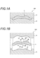
- FIG. 1 is a cross-sectional view of a lens mold and an optical lens for explaining an embodiment of the present invention
- FIG. 1A is an explanatory view showing a state in which the optical lens is taken out in a closed state
- FIG. is there.
- It is sectional drawing of an optical lens.
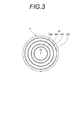
- It is a top view of the optical lens which shows the arrangement pattern of a concave mark.
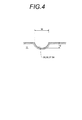
- It is sectional drawing which shows the cross-sectional shape of a concave mark.
- FIG. 7B are process explanatory views showing how the workpiece is processed. It is explanatory drawing which shows typically the mode of the shape measurement of the lens part by a shape measuring apparatus. It is explanatory drawing which shows typically the scanning system with respect to the optical lens of a stylus spin. 10A to 10C are cross-sectional views of various concave marks. It is a top view of the optical lens which shows the other arrangement pattern of a concave mark. It is explanatory drawing which shows typically the other scanning system with respect to the optical lens of a stylus spin. It is a top view which shows the concave mark extended radially. It is a perspective view which shows the cylindrical lens as an optical lens. It is a block diagram which shows an imaging module. It is a graph which shows the relationship between the ratio which the groove area of the concave mark occupies with respect to the area of a lens effective optical surface, and MTF reduction
- FIG. 1 is a cross-sectional view of a lens mold and an optical lens for explaining an embodiment of the present invention.
- FIG. 1A shows a state in which the lens mold is closed, and FIG. It is explanatory drawing which shows.
- the lens mold 100 includes an upper mold 13 and a lower mold 15 for molding a disk-shaped optical lens 11.
- the optical lens 11 is a meniscus lens made of transparent resin in which one lens surface 17 on the upper side in the drawing and the other lens surface 19 on the lower side have different shapes.
- the upper mold 13 and the lower mold 15 shown in FIG. 1B each have a lens transfer portion 21 that transfers one lens surface 17 of the optical lens 11 and a lens transfer portion 23 that transfers the other lens surface 19.
- the lens transfer portion 21 of the upper mold 13 is formed with a plurality of convex transfer portions 25 and 27, the details of which will be described later, protruding outward from the transfer surface, and the lens transfer portion 23 of the lower mold 15 will be described in detail later.
- a plurality of convex transfer portions 29 and 31 are formed to protrude outward from the transfer surface.
- the plurality of convex transfer portions 25, 27, 29, 31 transfer and form concave marks 33, 35, 37, 39, which will be described in detail later, on the lens surfaces 17, 19 of the optical lens 11.
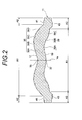
- FIG. 2 shows a cross-sectional view of the optical lens 11.
- Each lens surface 17 and 19 of the optical lens 11 has a lens part A1 having refractive power and a lens peripheral part A2 extending on the outer periphery of the lens part A1.
- the lens portion A1 is an aspheric lens, and the lens peripheral portion A2 is formed with flat portions 41, 43 and the like for joining the optical lens 11 to the lens holder and the lenses.
- FIG. 3 shows a plan view of the optical lens showing the arrangement pattern of the concave marks 33 and 35.
- a dot-like concave mark 33 formed at the position of the lens optical axis Ax, and a concave mark serving as a plurality of continuous grooves formed concentrically around the concave mark 33.
- 35 35A, 35B, 35C, 35D).
- the lens surface 19 of the optical lens 11 has a concave mark 37 formed at the position of the lens optical axis Ax, and a concave mark 39 (a plurality of continuous grooves formed concentrically around the concave mark 37). 39A, 39B, 39C).
- These concave marks 33, 35, 37, 39 are recessed from the lens surfaces 17, 19 and are formed in the lens effective optical surface of the lens portion A 1 of the optical lens 11.
- the concave marks 33, 35, 37, 39 coincide with the lens transfer portions 21, 23 of the lens mold 100, in which the lens shape in the lens portion A 1 of the optical lens 11 is produced based on the prescribed lens shape design data. It is a mark to measure whether or not.
- the shape of the lens transfer portions 21 and 23 of the lens mold 100 is corrected according to the measurement result obtained by measuring the positions of the concave marks 33, 35, 37 and 39.
- Fig. 4 shows the cross-sectional shape of the concave mark.
- the cross-sectional shape of each concave mark 33, 35, 37, 39 is the width W of the radial groove from the lens optical axis toward the lens outer periphery when the diameter D of the lens portion A1 of the optical lens 11 is 1.5 mm to 4 mm. Is 0.05 ⁇ m or more and 14 ⁇ m or less.
- the depth d of the groove is 0.05 ⁇ m or more and 5 ⁇ m or less.
- the total area of the concave marks in the lens effective optical surface of the lens portion A1 is set to 1.2% or less of the area of the lens effective optical surface.
- the lens effective optical surface here means a lens range that transmits a light beam that contributes to generation of a captured image by an image sensor (see FIG. 15) described later.
- the width W and the depth d of the groove are less than 0.05 ⁇ m, the accuracy of detecting the groove by the shape measuring device described later is lowered.
- the depth d of the groove exceeds 5 ⁇ m, the amount of light directed to the image sensor decreases due to an increase in diffraction intensity of incident light, local refraction caused by the groove, or the like. As a result, the image quality is deteriorated in the captured image. Therefore, the groove depth d is preferably 5 ⁇ m or less.
- the value of the modulation transfer function (MTF) representing the lens resolution of the lens portion A1 is not greatly reduced under the conditions of the dimension range of the concave mark and the total arrangement area. Specifically, by setting the groove width W and depth d in the above ranges, the concave mark is compared with the MTF value for the lens part having the same configuration except that the concave mark is not formed with the lens part. The rate of decrease from the MTF value when no film is formed is within 5%. If the reduction rate of MTF is within 5%, even if the concave mark is arranged in the lens effective optical surface that contributes to the image formation of the lens portion A1, the resolution of the actual lens is hardly affected.
- MTF modulation transfer function
- the concave marks 33 and 37 are preferably provided on the lens optical axis Ax because it is easy to grasp the rotationally symmetrical lens shape change, but the concave marks 33 and 37 may not be provided on the lens optical axis Ax. Even in this case, the position of the lens optical axis Ax can be obtained from the other concave marks 35 and 39.
- the concave marks 35 and 39 are formed concentrically, so that each concave mark is arranged on a line that is equidistant from the lens optical axis Ax with the lens optical axis Ax as the center. Therefore, it becomes easy to calculate the amount of contraction of the lens, and it becomes easy to correct the shape of the molding die described later.
- FIG. 5 is a flowchart showing a procedure from the production of the lens mold to the molding of the optical lens.
- a lens design for obtaining desired optical performance is performed, and the lens shape is determined (S1).
- each shape of the lens mold that molds the determined lens shape is determined (S2).
- the die processing apparatus 51 mainly fixes a spindle head 57 that rotates in the R direction and a tool 59 while a material that is a prototype of the upper mold 13 or the lower mold 15 that is the workpiece 53 is fixed by the chuck 55. And a carriage 61 that can move in the direction of the radius of rotation of the workpiece 53 (x direction).
- the headstock 57 is movable in the advancing / retreating direction (z direction) with respect to the tool 59, and the headstock 57 and the carriage 61 are installed on a common base 63.
- the workpiece 53 is fixed to the chuck 55 of the mold processing apparatus 51, and the workpiece 53 is driven to rotate. Then, the headstock 57 is moved in the z direction to cut the work 53 at the tip of the tool 59, and the carriage 61 is moved in the x direction to feed the tool 59.
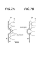
- FIGS. 7 (A) and 7 (B) The state of machining the workpiece 53 at this time is schematically shown in FIGS. 7 (A) and 7 (B).
- the tool 59 When cutting the workpiece 53 with the tool 59, as shown in FIG. 7A, while feeding the tool 59 along the end surface 67 of the workpiece 53, the tool 59 is cut in the cutting direction along the desired lens shape. Advance and retreat. Then, at the positions of the convex transfer portions 25, 27, 29, and 31 protruding from the end surface 67 in the lens shape, the tool 59 is advanced and retracted in the cutting direction along the shape of the convex transfer portions 25, 27, 29, and 31.
- the convex shape of the convex transfer portions 25, 27, 29, 31 can be easily processed at the tip of the tool 59, but conversely, it is a concave shape. In some cases, problems arise.
- Fig. 7 (B) shows a case where a concave shape is cut with a tool as a reference. If the tip edge of the tool 59 for cutting the workpiece 53 is too thick with respect to the concave shape to be formed, it cannot be processed into an accurate concave shape. That is, in order to form a desired concave shape on the surface of the workpiece 53, if the tip of the tool 59 is too thick with respect to the concave shape, the tip edge of the tool 59 cannot be applied to the cutting point. As a result, even if the tool 59 is moved along the desired concave shape and cut, the formed concave shape does not match the desired shape. In general, the blade width at the tip of the tool 59 is about 1 ⁇ m even if it is an extremely small type, and a groove narrower than this blade width cannot be machined.
- the convex transfer portions 25, 27, 29, and 31 are formed on the lens transfer portions 21 and 23 of the upper die 13 and the lower die 15, so that the transfer portions with extremely narrow protrusion widths are formed. Can be easily formed.
- the optical lens is test-molded using the upper mold 13 and the lower mold 15 produced by forming the desired lens shape and the convex convex transfer portion on the work 53 as described above (S4). ).
- a translucent resin is supplied into the cavity between the upper mold 13 and the lower mold 15 thus manufactured, and the lens of the upper mold 13 is used.
- the lens shape and convex transfer portions 25, 27, 29, and 31 are transferred to the translucent resin by the transfer portion 21 and the lens transfer portion 23 of the lower mold 15.
- the optical lens 11 in which the lens portion having a desired shape and the concave marks 33, 35, 37, and 39 are formed on the lens effective optical surface that contributes to the image formation of the lens portion is obtained.
- the optical lens 11 obtained by the test molding is attached to a shape measuring instrument for measuring the lens shape, and the three-dimensional shape of the lens portion is measured (S5).
- a shape measuring instrument for measuring the lens shape
- the shape measuring device for example, UA3P manufactured by Panasonic Corporation can be used, but the shape measuring device is not particularly limited.
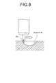
- FIG. 8 schematically shows how the shape of the lens portion is measured by the shape measuring device.
- the shape measuring device scans the surface of the optical lens 11 with the tip of the stylus spin 69 in contact with it, and amplifies the displacement information obtained from the stylus spin 69 to detect the curved surface shape.
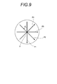
- FIG. 9 schematically shows a scanning method for the styluspin optical lens.
- the relative scanning of the optical lens 11 and the stylus spin 69 can be a scanning method in which scanning along a radial direction passing through the lens center O is repeated for a plurality of rotation angles ⁇ . That is, after scanning in the P1 direction along the radial direction, scanning in the P2 direction rotated by the rotation angle ⁇ from the P1 direction, and further scanning in the P3 direction rotated by the rotation angle ⁇ from the P2 direction are repeated.
- the rotation angle ⁇ is made finer, the number of points intersecting the concave mark increases, and the lens shape measurement accuracy can be improved.
- the relative movement between the stylus spin and the optical lens 11 only needs to move either one relative to the other. For example, the optical lens 11 moves in the horizontal plane, and the stylus spin is fixed with respect to the horizontal plane. Thus, it may be configured to be movable in the vertical direction according to the lens shape.
- the shape of the lens portion of the optical lens 11 is measured, and the position data (rotation angle ⁇ , radius distance r) and height data (detected from the concave marks 33, 35, 37, 39 of the optical lens 11) and height data ( The surface shape measurement data including the height h) at the rotation angle ⁇ radius distance r is obtained.
- the height h at the detection position ⁇ , r of the concave mark is known, and the positions other than the placement point of the concave mark are interpolated from the measurement data of the surrounding concave marks. The height can be determined. Therefore, the three-dimensional shape of the entire lens portion of the optical lens 11 can be grasped from the surface shape actual measurement data.
- the obtained surface shape measurement data is compared with the lens shape design data used as a production standard for the lens mold.
- the test-molded optical lens 11 does not match the shape of the prescribed lens shape design data due to the influence of shrinkage of the material itself in the cooling process, generation of stress, etc. due to the molded shape. Therefore, difference data for determining the surface shape of the test-molded optical lens 11 to match the surface shape based on the lens shape design data is obtained.
- the optical lens 11 has a rotationally symmetric shape with respect to the lens optical axis Ax.
- the optical lens 11 and the lens mold are formed with reference to a gate mark remaining on the surface of the optical lens at the gate connection position at the time of lens molding. A corresponding position around the lens optical axis Ax is obtained. Thereby, the corresponding position between the optical lens 11 and the lens mold can be uniquely determined.
- the lens mold is processed again until it becomes smaller than that value (repeats S3 to S5). In that case, a lens mold is produced again based on the lens shape correction data obtained by correcting the prescribed lens shape design data with the difference data.
- the optical lens 11 is molded using the lens mold used for the test molding as it is (S7).
- the shape correction method of the lens mold and the method of molding the optical lens after correcting the shape of the lens mold, the lens shape of the optical lens formed by the test molding using the lens mold is measured, and the lens shape After confirming that the difference from the design data is less than a predetermined value, the optical lens 11 is molded using the lens mold for which the shape correction / difference has been confirmed. For this reason, the lens shape of the optical lens 11 finally obtained has been confirmed by test molding, and the same lens shape as the shape of the lens shape design data can be reliably obtained.
- the shape of the lens portion is an aspherical shape
- there is no reference for the aspherical portion so it is not possible to know which part is contracted in which direction and how much. For this reason, it is difficult to associate which part of the lens mold corresponds to which part of the optical lens.
- the concave mark transferred by the convex transfer part of the lens mold is formed in the effective optical surface of the optical lens, so the corresponding position between the lens mold and the optical lens is accurately grasped. it can. Therefore, when measuring the aspherical shape of the optical lens after molding and feeding back the shape of the lens mold, it is possible to accurately determine what amount should be corrected at which position of the lens mold.
- the lens mold can be corrected with high accuracy. Therefore, the shape of the optical lens can be molded with high accuracy according to the shape of the lens shape design data.
- an aspherical lens requiring high resolution needs to achieve a strict target shape accuracy such as a shape error of 0.1 ⁇ m or less when the lens diameter is about 1 mm, for example. Even when such highly accurate molding is required, according to the present method, an optical lens having a target shape accuracy can be stably molded at a low cost while maintaining a high resolution.
- the optical lens 11 finally obtained is a lens mold that has been confirmed that the shape of the test molded optical lens coincides with the lens shape design data at a satisfactory level after the correction of the lens mold described above. It is molded. Therefore, the reliability of the lens shape is high compared with the case where the final correction data is obtained and the lens mold is produced again.
- the concave marks 33, 35, 37 and 39 transferred to the test molded optical lens remain as they are.
- the size of these concave marks 33, 35, 37, and 39 is very small, and even if they remain in the effective optical range of the optical lens 11, they hardly affect the optical performance of the lens.
- the concave mark remaining in the optical lens 11 can be used to serve as product quality traceability. For example, when continuously forming an optical lens with a lens transfer mold after correcting the shape, if a problem occurs in the lens properties, etc., the lens shape of each molded optical lens is measured using a concave mark. Thus, it is possible to confirm the occurrence of problems over time.
- the concave marks 33, 35, 37, and 39 can change the shape of the concave surface to various shapes.
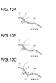
- 10A to 10C are cross-sectional views of various concave marks.
- the concave mark 71 shown in FIG. 10A has an aspheric concave surface, and the inclination angle ⁇ on the lens inner side with respect to the lens surface normal L at the boundary with the lens surface 73 is 40 ° or more and 80 ° or less. . Since the concave surface is aspherical, the width of the concave mark can be defined wider than when the concave surface is formed as a spherical surface. Therefore, when the stylus spin 69 of the shape measuring apparatus shown in FIG. 8 is brought into contact with the concave surface and scanned, the measurement distance can be made longer than that of the spherical surface, and the center position of the concave mark 71 can be easily obtained.
- the concave mark 77 shown in FIG. 10B has a spherical concave surface, and an inclination angle ⁇ with respect to the lens surface normal L is 40 ° or more and 80 ° or less.
- the concave mark 79 shown in FIG. 10C has a concave surface with a mountain-shaped cross section, and the inclination angle ⁇ with respect to the lens surface normal L is not less than 40 ° and not more than 80 °.
- the opening angle ⁇ of the bottom portion 81 is an obtuse angle so that the stylus spin 69 can be scanned smoothly. Since the concave surface has a mountain-shaped cross section, the center position of the concave mark 79 can be easily detected as the bottom portion 81.
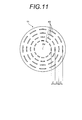
- FIG. 11 is a plan view of an optical lens showing another arrangement pattern of concave marks.
- the concave marks may be discontinuous concave marks 45 arranged in a distributed manner other than the continuous marks centered on the lens optical axis Ax.
- the concave mark 45 in this case is formed along the circumference of a plurality of concentric circles centering on the lens optical axis Ax, and the concave mark is divided by providing a blank area for each specified center angle.
- the dividing pattern is preferably the same in each concentric circle, in which case all the stylus spins of the shape measuring device are scanned along the radial direction where the concave mark 45 exists through the lens optical axis Ax.
- the concave mark 45 on the concentric circle can be detected.
- the concave mark 45 By dividing the concave mark 45, the total arrangement area of the concave mark 45 can be reduced. Therefore, when the concave mark 45 has the same total arrangement area, the concave mark can be formed into a high-density arrangement pattern in which the interval C between the concave mark groups at the same radial distance from the lens center is narrowed, and the measurement accuracy of the lens shape Can be improved.
- the concave mark only needs to be formed along a simple closed curve that includes the lens optical axis Ax of the lens portion.
- it may be an annular mark such as a polygonal shape or an elliptical shape in a plan view from the lens optical axis Ax direction. Since the concave mark is a simple closed curve, when the stylus spin of the shape measuring apparatus is scanned along an arbitrary radial direction passing through the lens optical axis Ax, the stylus spin always strikes any part of the concave mark. Therefore, the shape of the lens portion around the lens optical axis Ax can be reliably obtained.
- the concave marks are arranged concentrically on the optical lens.
- the following concave mark arrangement pattern can be obtained by changing the stylus spin scanning method. You can also.
- FIGS. 12A and 12B schematically show other scanning methods for the styluspin optical lens.
- the scanning method shown in FIG. 12A scans P1 to P5 along the circumference of a plurality of concentric circles centering on the lens center O.
- this scanning method as shown in FIG. 13, it can be a concave mark 47 extending radially from the center of the optical lens 11.
- the shape measuring device (FIG. 8) defines the center of the lens that is the intersection of the concave marks 47, and forms the radial distances r1, r2,... (FIG. 12A) for scanning the stylus spin 69. If managed accurately on the measuring device side, the lens shape can be measured in the same manner as the concave mark shown in FIG. As the rotation angle ⁇ is made finer, the number of points intersecting the concave mark increases, and the lens shape measurement accuracy can be improved.
- the disk-shaped aspheric meniscus lens is used as the optical lens, but the present invention is not limited to this.
- the lens may be a convex lens or a concave lens that is not a meniscus lens, or a spherical lens.
- the cylindrical lens 83 shown in FIG. 14 may be used.
- the line segment M1 that is the lens optical axis position of the lens portion A1 of the cylindrical lens 83, the line segments M2 and M2 that are parallel to the line segment M1 and are equidistant from the line segment M, and the line Concave marks are respectively formed on the minutes M3 and M3.
- the concave marks are also arranged symmetrically along a line that is equidistant from the lens optical axis with the lens optical axis as the center. Then, the lens shape of the cylindrical lens 83 is measured by scanning the stylus spin 69 of the shape measuring device along the P direction perpendicular to each concave mark on each concave mark at the position of each line segment M1, M2, M3. it can.
- the arrangement direction of the concave mark and the scanning direction of the stylus spin 69 may be reversed.
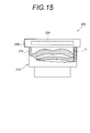
- the above-described optical lens 11 can be used, for example, in the imaging module shown in FIG.
- the imaging module 200 includes a lens unit 210 and an imaging unit 230 including an imaging element 220 that images a subject through the lens unit 210.
- the lens unit 210 includes a lens holder 211 and at least one optical lens 11 held by the lens holder 211.
- the optical lens 11 held by the lens holder 211 collects light from the lower subject side in the figure to the upper imaging unit 230 in the figure, and the imaging unit 230 captures an optical image of the subject and outputs a captured image signal. To do.
- the imaging module 200 is supported by a support member such as a substrate (not shown), and is disposed in a housing of an electronic device such as a digital camera or a vehicle-mounted camera, and serves as an imaging device.
- the imaging module 200 can be incorporated, for example, a PC (Personal Computer)
- An electronic device such as a built-in or external PC camera, an interphone with a camera, or a portable terminal device having a photographing function can be given.
- the portable terminal device include a mobile phone, a smartphone, a PDA (Personal Digital Assistants), a portable game machine, and the like.
- the present invention is not limited to the above-described embodiments, and those skilled in the art can make changes and applications based on combinations of the configurations of the embodiments, descriptions in the specification, and well-known techniques. This is also the scope of the present invention, and is included in the scope for which protection is sought.
- a concave mark As a concave mark, a first groove formed at the lens optical axis position and a second radius having a radius from the lens optical axis to the inside of the groove is 0.25 mm. A groove, a third groove of 0.50 mm, a fourth groove of 0.72 mm, a fifth groove of 1.00 mm, and a sixth groove of 1.25 mm.
- the MTF measurement is performed in the form of an imaging module in which five optical lenses are housed, as in the imaging module shown in FIG. 15, and the concave mark is formed only on the optical lens closest to the subject. Measurement was made for each case where no mark was formed.
- the MTF decrease rate is a value indicating how much the MTF value measured with the concave mark is lower than the MTF value measured without the concave mark.
- FIG. 16 is a graph showing the relationship between the ratio of the groove area of the concave mark to the area of the lens effective optical surface and the MTF reduction rate.
- a measuring instrument manufactured by Trioptics was used for measurement of MTF.
- the groove width is in the range of 5 to 14 ⁇ m
- the groove depth d is 5 ⁇ m
- the concave mark in the lens effective optical surface is the total area of the lens effective optical surface.
- An optical lens having a lens portion having refractive power In the lens effective optical surface that contributes to the image formation of the lens part, having a concave mark formed to be recessed from the surface of the lens part,
- the concave lens is an optical lens having a width of 0.05 ⁇ m or more and 14 ⁇ m or less, and a depth of the depression of 0.05 ⁇ m or more and 5 ⁇ m or less.
- the total area of the concave mark in the lens effective optical surface of the lens unit is an optical lens in which a ratio of the area of the lens effective optical surface to the lens effective optical surface is 1.2% or less.
- the optical lens according to (1) or (2), A plurality of the concave marks are formed along a line that is equidistant from the optical axis with the optical axis of the lens portion as a center.
- the concave mark is an optical lens formed along a simple closed curve including the optical axis of the lens unit.
- the optical lens according to (4), The concave mark is an optical lens formed along a circumference of a circle centered on the optical axis.
- the optical lens according to (6), The concave lens is an optical lens formed at equal intervals along the circumference of a circle centered on the optical axis.
- the optical lens according to any one of (1) to (7), The concave mark is an optical lens formed along a plurality of concentric circles centered on the optical axis.
- the optical lens according to any one of (1) to (8), The concave lens is an optical lens having a width of 0.05 ⁇ m or more and 14 ⁇ m or less, and a depth of the depression of 0.05 ⁇ m or more and 5 ⁇ m or less.
- the lens unit is an optical lens that is an aspheric lens.
- An electronic device in which the electronic device according to (14) is an in-vehicle camera.
- An electronic device in which the electronic device according to (14) is a digital camera.
- An optical lens manufacturing method for forming an optical lens using a lens mold having a lens-shaped transfer surface The lens mold has a convex transfer portion formed to protrude outward from the lens-shaped transfer surface, and the convex transfer portion has a lens effective optical surface that contributes to image formation of the lens portion. Molding an optical lens having a concave mark recessed from the surface of the lens part, A method for manufacturing an optical lens, wherein the concave mark is formed with a width of 0.05 ⁇ m or more and 14 ⁇ m or less and a depth of the depression of 0.05 ⁇ m or more and 5 ⁇ m or less. (18) The lens molding die used in the method for producing an optical lens according to (17).
Landscapes
- Engineering & Computer Science (AREA)
- Physics & Mathematics (AREA)
- Health & Medical Sciences (AREA)
- Manufacturing & Machinery (AREA)
- Ophthalmology & Optometry (AREA)
- Mechanical Engineering (AREA)
- General Physics & Mathematics (AREA)
- Optics & Photonics (AREA)
- Moulds For Moulding Plastics Or The Like (AREA)
- Eyeglasses (AREA)
Abstract
Description
そこで、レンズ設計値通りの光学レンズを成形するには、レンズ成形型を用いて光学レンズを成形した後、この成形した光学レンズの形状を測定し、測定結果に応じてレンズ成形型に適切な形状にする補正加工を行なう。例えば、特許文献1、2には、レンズ成形型のレンズ有効部の外側にマーキングを設け、このマーキングが転写されたレンズ成形品の表面形状を測定すること、及び、表面形状の測定値と設計値とのずれである形状誤差を算出し、この形状誤差の情報に応じてレンズ成形型の形状を補正することが記載されている。
(1) 屈折力を有するレンズ部を有する光学レンズであって、
上記レンズ部の結像に寄与するレンズ有効光学面内に、上記レンズ部の表面から窪んで形成された凹状マークを有し、
上記凹状マークは、幅が0.05μm以上、14μm以下であり、窪みの深さが0.05μm以上、5μm以下である光学レンズ。
(2) 上記光学レンズが少なくとも1枚、レンズホルダに保持されたレンズユニット。(3) 上記レンズユニットと、
上記レンズユニットを通して被写体を撮像する撮像部と、
を備える撮像モジュール。
(4) 上記撮像モジュールが搭載された電子機器。
(5) レンズ形状の転写面を有するレンズ成形型を用いて光学レンズを成形する光学レンズの製造方法であって、
上記レンズ成形型は、上記レンズ形状の転写面から外側に突出して形成される凸状転写部を有し、その凸状転写部によって、レンズ部の結像に寄与するレンズ有効光学面内に、上記レンズ部の表面から窪んだ凹状マークを有する光学レンズを成形し、
上記凹状マークを、幅が0.05μm以上、14μm以下であり、窪みの深さが0.05μm以上、5μm以下で形成する光学レンズの製造方法。
(6) 上記光学レンズの製造方法に用いる上記レンズ成形型。
(7) 上記レンズ成形型の形状補正方法であって、
規定のレンズ表面形状を表すレンズ形状設計データに基づいて作製された上記レンズ成形型を用いて、上記凹状マークを有する光学レンズを成形し、
成形された上記光学レンズの上記凹状マークの位置を検出して、上記光学レンズのレンズ表面形状を表す表面形状実測データを求め、
上記表面形状実測データと上記レンズ形状設計データとを比較して、上記光学レンズの表面形状を上記レンズ形状設計データに基づく表面形状に一致させる差分データを求め、
上記レンズ形状設計データを上記差分データにより補正したレンズ形状補正データに基づいて、上記レンズ成形型を再度作製するレンズ成形型の形状補正方法。
図1は本発明の実施形態を説明するためのレンズ成形型と光学レンズの断面図であり、(A)はレンズ成形型の型閉じ状態、(B)は型開き状態で光学レンズを取り出す様子を示す説明図である。
図1(A)に示すように、レンズ成形型100は、円盤状の光学レンズ11を成形する上型13と下型15とを有する。光学レンズ11は、図中上側となる一方のレンズ表面17と、下側となる他方のレンズ表面19とが、互いに異なる形状とされた透明樹脂からなるメニスカスレンズである。
先ず、光学レンズ11の形状について説明する。
図2に光学レンズ11の断面図を示す。光学レンズ11の各レンズ表面17,19は、屈折力を有するレンズ部A1と、レンズ部A1の外周に延設されたレンズ周辺部A2とを有する。レンズ部A1は非球面レンズであり、レンズ周辺部A2は光学レンズ11をレンズホルダやレンズ同士と接合する平坦部41,43等が形成されている。
=λ/δ : θは回折角、λは光の波長)によれば、隣接する凹状マーク同士の間隔δが十分に大きい場合、回折角θが略ゼロとなる。そのため、上記した凹状マークの寸法範囲では実質的に回折は発生せず、レンズの結像に影響する不要光は発生しない。
次に、上記光学レンズ11を成形するレンズ成形型の作製手順と、レンズ成形型による光学レンズの成形について説明する。
図5は、レンズ成形型の作製と光学レンズの成形までの手順を示すフローチャートである。
光学レンズ11を成形するにあたり、先ず、所望の光学性能を得るためのレンズ設計を行い、レンズ形状を決定する(S1)。次に、決定したレンズ形状を成形するレンズ成形型の各形状を決定する(S2)。
次に、光学レンズ11の凹状マーク(レンズ成形型の凸状転写部)の変形例について説明する。
凹状マーク33,35,37,39は、その凹面の形状を種々の形状に変更できる。図10(A)~(C)に種々の凹状マークの断面図を示した。図10(A)に示す凹状マーク71は、凹面が非球面形状であり、レンズ面73との境界部におけるレンズ面法線Lに対するレンズ内側の傾斜角αは40°以上、80°以下である。凹面が非球面形状であることにより、凹面を球面で形成する場合よりも凹状マークの幅を広く規定できる。そのため、図8に示す形状測定装置のスタイラスピン69を凹面に接触させて走査した際に、測定距離を球面の場合よりも長くでき、凹状マーク71の中心位置を求めやすい。
図11に凹状マークの他の配置パターンを示す光学レンズの平面図を示す。凹状マークはレンズ光軸Axを中心とする連続したマークである以外にも、分散配置された不連続の凹状マーク45であってもよい。この場合の凹状マーク45は、レンズ光軸Axを中心とする複数の同心円の円周に沿って形成され、規定の中心角度毎に空白領域を設けることで、凹状マークを分断している。分断パターンは各同心円で同じであることが好ましく、その場合には、形状測定装置のスタイラスピンを、レンズ光軸Axを通り凹状マーク45が存在する半径方向に沿って走査することによって、全ての同心円上の凹状マーク45を検出できる。
上記では、光学レンズとして円盤状の非球面メニスカスレンズを用いて説明したが、これに限らない。例えば、メニスカスレンズでない凸レンズ、凹レンズであってもよく、球面レンズであってもよい。また、図14に示すシリンドリカルレンズ83であってもよい。シリンドリカルレンズ83とした場合、シリンドリカルレンズ83のレンズ部A1のレンズ光軸位置となる線分M1と、この線分M1と平行で、線分Mから等距離となる線分M2,M2、及び線分M3,M3とに、それぞれ凹状マークを形成する。線分M2,M3の位置は、線分M1に対して対称位置であるため、凹状マークもレンズ光軸を中心として、レンズ光軸から等距離となる線上に沿って対称に配置される。そして、各線分M1,M2,M3の位置の各凹状マーク上を、各凹状マークに直交するP方向に沿って形状測定装置のスタイラスピン69を走査することで、シリンドリカルレンズ83のレンズ形状を測定できる。なお、凹状マークの配置方向とスタイラスピン69の走査方向とを逆転させた構成にしてもよい。
内蔵型又は外付け型のPC用カメラ、カメラ付きインターフォン、或いは、撮影機能を有する携帯端末装置等の電子機器を挙げることができる。携帯端末装置としては、例えば、携帯電話機やスマートフォン、PDA(Personal Digital Assistants)、携帯型ゲーム機
等が挙げられる。

(1) 屈折力を有するレンズ部を有する光学レンズであって、
上記レンズ部の結像に寄与するレンズ有効光学面内に、上記レンズ部の表面から窪んで形成された凹状マークを有し、
上記凹状マークは、幅が0.05μm以上、14μm以下であり、窪みの深さが0.05μm以上、5μm以下である光学レンズ。
(2) (1)に記載の光学レンズであって、
上記レンズ部のレンズ有効光学面内における上記凹状マークの総面積は、上記レンズ有効光学面の面積に占める割合が1.2%以下である光学レンズ。
(3) (1)又は(2)に記載の光学レンズであって、
上記凹状マークは、上記レンズ部の光軸を中心として、その光軸から等距離となる線上に沿って複数形成された光学レンズ。
(4) (1)又は(2)に記載の光学レンズであって、
上記凹状マークは、上記レンズ部の光軸を内包する単純閉曲線に沿って形成された光学レンズ。
(5) (4)に記載の光学レンズであって、
上記凹状マークは、上記光軸を中心とする円の円周に沿って形成された光学レンズ。
(6) (5)に記載の光学レンズであって、
上記凹状マークは、上記光軸を中心とする円の円周に沿って複数形成された光学レンズ。
(7) (6)に記載の光学レンズであって、
上記凹状マークは、上記光軸を中心とする円の円周に沿って等間隔に形成された光学レンズ。
(8) (1)乃至(7)のいずれか一項に記載の光学レンズであって、
上記凹状マークは、上記光軸を中心とする複数の同心円に沿って形成された光学レンズ。
(9) (1)乃至(8)に記載の光学レンズであって、
上記凹状マークは、幅が0.05μm以上、14μm以下であり、窪みの深さが0.05μm以上、5μm以下である光学レンズ。
(10) (1)乃至(9)のいずれか一項に記載の光学レンズであって、
上記レンズ部は、非球面レンズである光学レンズ。
(11) (1)乃至(10)のいずれか一項に記載の光学レンズであって、
上記レンズ部は、メニスカスレンズであり、
上記凹状マークは、上記レンズ部の両レンズ面にそれぞれ形成された光学レンズ。
(12) (1)乃至(11)のいずれか一項に記載の光学レンズが少なくとも1枚、レンズホルダに保持されたレンズユニット。
(13) (12)に記載のレンズユニットと、
上記レンズユニットを通して被写体を撮像する撮像部と、
を備える撮像モジュール。
(14) (13)に記載の撮像モジュールが搭載された電子機器。
(15) (14)に記載の電子機器が車載用カメラである電子機器。
(16) (14)に記載の電子機器がデジタルカメラである電子機器。
(17) レンズ形状の転写面を有するレンズ成形型を用いて光学レンズを成形する光学レンズの製造方法であって、
上記レンズ成形型は、上記レンズ形状の転写面から外側に突出して形成される凸状転写部を有し、その凸状転写部によって、レンズ部の結像に寄与するレンズ有効光学面内に、上記レンズ部の表面から窪んだ凹状マークを有する光学レンズを成形し、
上記凹状マークを、幅が0.05μm以上、14μm以下であり、窪みの深さが0.05μm以上、5μm以下で形成する光学レンズの製造方法。
(18) (17)に記載の光学レンズの製造方法に用いる上記レンズ成形型。
(19) (18)に記載のレンズ成形型の形状補正方法であって、
規定のレンズ表面形状を表すレンズ形状設計データに基づいて作製された上記レンズ成形型を用いて、上記凹状マークを有する光学レンズを成形し、
成形された上記光学レンズの上記凹状マークの位置を検出して、上記光学レンズのレンズ表面形状を表す表面形状実測データを求め、
上記表面形状実測データと上記レンズ形状設計データとを比較して、上記光学レンズの表面形状を上記レンズ形状設計データに基づく表面形状に一致させる差分データを求め、
上記レンズ形状設計データを上記差分データにより補正したレンズ形状補正データに基づいて、上記レンズ成形型を再度作製するレンズ成形型の形状補正方法。
13 上型
15 下型
21,23 レンズ転写部
25,27,29,31 凸状転写部
33,35,37,39 凹状マーク
100 レンズ成形型
200 撮像モジュール
210 レンズユニット
220 撮像素子
230 撮像部
A1 レンズ部
Ax レンズ光軸
Claims (19)
- 屈折力を有するレンズ部を有する光学レンズであって、
前記レンズ部の結像に寄与するレンズ有効光学面内に、前記レンズ部の表面から窪んで形成された凹状マークを有し、
前記凹状マークは、幅が0.05μm以上、14μm以下であり、窪みの深さが0.05μm以上、5μm以下である光学レンズ。 - 請求項1に記載の光学レンズであって、
前記レンズ部のレンズ有効光学面内における前記凹状マークの総面積は、前記レンズ有効光学面の面積に占める割合が1.2%以下である光学レンズ。 - 請求項1又は請求項2に記載の光学レンズであって、
前記凹状マークは、前記レンズ部の光軸を中心として、該光軸から等距離となる線上に沿って複数形成された光学レンズ。 - 請求項1又は請求項2に記載の光学レンズであって、
前記凹状マークは、前記レンズ部の光軸を内包する単純閉曲線に沿って形成された光学レンズ。 - 請求項4に記載の光学レンズであって、
前記凹状マークは、前記光軸を中心とする円の円周に沿って形成された光学レンズ。 - 請求項5に記載の光学レンズであって、
前記凹状マークは、前記光軸を中心とする円の円周に沿って複数形成された光学レンズ。 - 請求項6に記載の光学レンズであって、
前記凹状マークは、前記光軸を中心とする円の円周に沿って等間隔に形成された光学レンズ。 - 請求項1乃至請求項7のいずれか一項に記載の光学レンズであって、
前記凹状マークは、前記光軸を中心とする複数の同心円に沿って形成された光学レンズ。 - 請求項1乃至請求項8のいずれか一項に記載の光学レンズであって、
前記凹状マークは、幅が0.05μm以上、14μm以下であり、窪みの深さが0.05μm以上、5μm以下である光学レンズ。 - 請求項1乃至請求項9のいずれか一項に記載の光学レンズであって、
前記レンズ部は、非球面レンズである光学レンズ。 - 請求項1乃至請求項10のいずれか一項に記載の光学レンズであって、
前記レンズ部は、メニスカスレンズであり、
前記凹状マークは、前記レンズ部の両レンズ面にそれぞれ形成された光学レンズ。 - 請求項1乃至請求項11のいずれか一項に記載の光学レンズが少なくとも1枚、レンズホルダに保持されたレンズユニット。
- 請求項12に記載のレンズユニットと、
前記レンズユニットを通して被写体を撮像する撮像部と、
を備える撮像モジュール。 - 請求項13に記載の撮像モジュールが搭載された電子機器。
- 請求項14に記載の電子機器が車載用カメラである電子機器。
- 請求項14に記載の電子機器がデジタルカメラである電子機器。
- レンズ形状の転写面を有するレンズ成形型を用いて光学レンズを成形する光学レンズの製造方法であって、
前記レンズ成形型は、前記レンズ形状の転写面から外側に突出して形成される凸状転写部を有し、該凸状転写部によって、レンズ部の結像に寄与するレンズ有効光学面内に、前記レンズ部の表面から窪んだ凹状マークを有する光学レンズを成形し、
前記凹状マークを、幅が0.05μm以上、14μm以下であり、窪みの深さが0.05μm以上、5μm以下で形成する光学レンズの製造方法。 - 請求項17に記載の光学レンズの製造方法に用いる前記レンズ成形型。
- 請求項18に記載のレンズ成形型の形状補正方法であって、
規定のレンズ表面形状を表すレンズ形状設計データに基づいて作製された前記レンズ成形型を用いて、前記凹状マークを有する光学レンズを成形し、
成形された前記光学レンズの前記凹状マークの位置を検出して、前記光学レンズのレンズ表面形状を表す表面形状実測データを求め、
前記表面形状実測データと前記レンズ形状設計データとを比較して、前記光学レンズの表面形状を前記レンズ形状設計データに基づく表面形状に一致させる差分データを求め、
前記レンズ形状設計データを前記差分データにより補正したレンズ形状補正データに基づいて、前記レンズ成形型を再度作製するレンズ成形型の形状補正方法。
Priority Applications (3)
| Application Number | Priority Date | Filing Date | Title |
|---|---|---|---|
| JP2015508436A JP5820957B2 (ja) | 2013-03-27 | 2014-03-20 | 光学レンズ、レンズユニット、撮像モジュール、電子機器、及び光学レンズの製造方法、レンズ成形型、レンズ成形型の形状補正方法 |
| CN201480017205.9A CN105050784B (zh) | 2013-03-27 | 2014-03-20 | 光学透镜、透镜单元、摄像模块及光学透镜的制造方法 |
| US14/843,949 US9703017B2 (en) | 2013-03-27 | 2015-09-02 | Optical lens, lens unit, imaging module, electronic device, optical lens production method, lens mold, and shape correction method for lens mold |
Applications Claiming Priority (2)
| Application Number | Priority Date | Filing Date | Title |
|---|---|---|---|
| JP2013067036 | 2013-03-27 | ||
| JP2013-067036 | 2013-03-27 |
Related Child Applications (1)
| Application Number | Title | Priority Date | Filing Date |
|---|---|---|---|
| US14/843,949 Continuation US9703017B2 (en) | 2013-03-27 | 2015-09-02 | Optical lens, lens unit, imaging module, electronic device, optical lens production method, lens mold, and shape correction method for lens mold |
Publications (1)
| Publication Number | Publication Date |
|---|---|
| WO2014157003A1 true WO2014157003A1 (ja) | 2014-10-02 |
Family
ID=51623980
Family Applications (1)
| Application Number | Title | Priority Date | Filing Date |
|---|---|---|---|
| PCT/JP2014/057886 Ceased WO2014157003A1 (ja) | 2013-03-27 | 2014-03-20 | 光学レンズ、レンズユニット、撮像モジュール、電子機器、及び光学レンズの製造方法、レンズ成形型、レンズ成形型の形状補正方法 |
Country Status (4)
| Country | Link |
|---|---|
| US (1) | US9703017B2 (ja) |
| JP (1) | JP5820957B2 (ja) |
| CN (1) | CN105050784B (ja) |
| WO (1) | WO2014157003A1 (ja) |
Families Citing this family (4)
| Publication number | Priority date | Publication date | Assignee | Title |
|---|---|---|---|---|
| CN107728241A (zh) * | 2017-10-27 | 2018-02-23 | 辽宁中蓝电子科技有限公司 | 一种光学镜片 |
| CN112115319B (zh) * | 2020-09-08 | 2024-03-01 | 亚琛科技(深圳)有限公司 | 模具溯源方法、系统及光学镜片模压设备自动装载机械手 |
| TWI796817B (zh) | 2021-10-28 | 2023-03-21 | 大立光電股份有限公司 | 成像透鏡組、成像鏡頭模組、相機模組與電子裝置 |
| CN115503160B (zh) * | 2022-10-18 | 2025-11-04 | 桐城联创电子有限公司 | 一种嵌合镜片模具的测试调整方法 |
Citations (6)
| Publication number | Priority date | Publication date | Assignee | Title |
|---|---|---|---|---|
| JPH08194193A (ja) * | 1995-01-18 | 1996-07-30 | Hoya Corp | コンタクトレンズのマーキング方法 |
| JPH08294976A (ja) * | 1995-04-26 | 1996-11-12 | Canon Inc | レンズ及びその成形型 |
| JP2002355821A (ja) * | 2001-03-27 | 2002-12-10 | Ricoh Co Ltd | 成形用型、成形用型の製造方法、成形用型の設計装置及び設計プログラム、成形方法、成形品、並びに光学システム |
| WO2005115712A1 (ja) * | 2004-05-31 | 2005-12-08 | Hoya Corporation | 成形型の設計方法、成形型及び成形品 |
| JP2007519020A (ja) * | 2003-07-09 | 2007-07-12 | スリーエム イノベイティブ プロパティズ カンパニー | 少なくとも1つのレンズセントレーションマークを有するレンズおよび同レンズの製造方法および使用方法 |
| JP2011212924A (ja) * | 2010-03-31 | 2011-10-27 | Brother Industries Ltd | レンズの成形型の製造方法 |
Family Cites Families (6)
| Publication number | Priority date | Publication date | Assignee | Title |
|---|---|---|---|---|
| JP3221813B2 (ja) | 1995-02-13 | 2001-10-22 | キヤノン株式会社 | プラスチックレンズ |
| JP2002243914A (ja) * | 2001-02-19 | 2002-08-28 | Hitachi Koki Co Ltd | レンズ修正装置、レンズ修正方法及びレンズ |
| US20050182489A1 (en) * | 2001-04-27 | 2005-08-18 | Peyman Gholam A. | Intraocular lens adapted for adjustment via laser after implantation |
| US20070273983A1 (en) * | 2006-05-26 | 2007-11-29 | Hebert Raymond T | Devices, methods, and systems for image viewing |
| JP4527201B2 (ja) * | 2008-07-15 | 2010-08-18 | 株式会社メニコン | 眼内レンズおよびその製造方法 |
| US9236522B2 (en) * | 2012-11-30 | 2016-01-12 | Robert Bosch Gmbh | MEMS infrared sensor including a plasmonic lens |
-
2014
- 2014-03-20 JP JP2015508436A patent/JP5820957B2/ja active Active
- 2014-03-20 CN CN201480017205.9A patent/CN105050784B/zh active Active
- 2014-03-20 WO PCT/JP2014/057886 patent/WO2014157003A1/ja not_active Ceased
-
2015
- 2015-09-02 US US14/843,949 patent/US9703017B2/en active Active
Patent Citations (6)
| Publication number | Priority date | Publication date | Assignee | Title |
|---|---|---|---|---|
| JPH08194193A (ja) * | 1995-01-18 | 1996-07-30 | Hoya Corp | コンタクトレンズのマーキング方法 |
| JPH08294976A (ja) * | 1995-04-26 | 1996-11-12 | Canon Inc | レンズ及びその成形型 |
| JP2002355821A (ja) * | 2001-03-27 | 2002-12-10 | Ricoh Co Ltd | 成形用型、成形用型の製造方法、成形用型の設計装置及び設計プログラム、成形方法、成形品、並びに光学システム |
| JP2007519020A (ja) * | 2003-07-09 | 2007-07-12 | スリーエム イノベイティブ プロパティズ カンパニー | 少なくとも1つのレンズセントレーションマークを有するレンズおよび同レンズの製造方法および使用方法 |
| WO2005115712A1 (ja) * | 2004-05-31 | 2005-12-08 | Hoya Corporation | 成形型の設計方法、成形型及び成形品 |
| JP2011212924A (ja) * | 2010-03-31 | 2011-10-27 | Brother Industries Ltd | レンズの成形型の製造方法 |
Also Published As
| Publication number | Publication date |
|---|---|
| CN105050784B (zh) | 2018-05-04 |
| US20150378066A1 (en) | 2015-12-31 |
| CN105050784A (zh) | 2015-11-11 |
| JP5820957B2 (ja) | 2015-11-24 |
| US9703017B2 (en) | 2017-07-11 |
| JPWO2014157003A1 (ja) | 2017-02-16 |
Similar Documents
| Publication | Publication Date | Title |
|---|---|---|
| KR101066449B1 (ko) | 형상 측정 방법 | |
| JP5820957B2 (ja) | 光学レンズ、レンズユニット、撮像モジュール、電子機器、及び光学レンズの製造方法、レンズ成形型、レンズ成形型の形状補正方法 | |
| CN102869477B (zh) | 自动校准 | |
| KR100956376B1 (ko) | 웨이퍼 렌즈의 정렬 방법 및 이를 통해 제작되는 웨이퍼렌즈 | |
| CN206505198U (zh) | 透镜 | |
| CN105627945A (zh) | 非球面元件中心与外圆中心偏离量的测量装置及测量方法 | |
| JP5189420B2 (ja) | 樹脂レンズおよび樹脂レンズの成形方法 | |
| JP4986148B2 (ja) | 光学素子の成形金型、成形金型の加工方法、光学素子、光学装置、光走査装置、画像表示装置、光ピックアップ装置 | |
| JP5721508B2 (ja) | 測定用工具を合わせるための工具ホルダ、測定装置、及びその測定装置の校正方法 | |
| JP2006058850A (ja) | 光学レンズ及びその製造方法 | |
| JP2003337018A (ja) | 3次元形状測定機 | |
| CN110275484A (zh) | 一种在单晶硅基板上形成微透镜阵列模具的方法 | |
| US7499220B2 (en) | Optical lens and method of manufacturing the same | |
| JP4418860B2 (ja) | レンズ用金型、その切削加工方法およびそれを使用したレンズの製造方法 | |
| KR20140102002A (ko) | 어레이 렌즈 및 어레이 렌즈 금형 | |
| WO2014208371A1 (ja) | 非球面レンズ、該非球面レンズを備えたレンズユニットの製造方法および該製造方法により製造されるレンズユニットならびにレンズ成形金型 | |
| JP5466313B2 (ja) | 眼鏡レンズの製造方法 | |
| JP5483227B2 (ja) | 眼鏡レンズの製造装置 | |
| KR102659151B1 (ko) | 스타일러스 및 측정 방법 | |
| JP3226753B2 (ja) | レンズ及びその成形型 | |
| CN112880585A (zh) | 非接触形状测定装置 | |
| JP2008030160A (ja) | 円形レンズの心取り方法と該方法を用いた円形レンズの製造方法 | |
| CN100497221C (zh) | 可精密控制芯厚的模仁及具有此模仁的模具组 | |
| KR102053838B1 (ko) | 렌즈 | |
| JP2002090137A (ja) | 立体形状測定方法およびこれを用いたプラスチックレンズの製造方法 |
Legal Events
| Date | Code | Title | Description |
|---|---|---|---|
| WWE | Wipo information: entry into national phase |
Ref document number: 201480017205.9 Country of ref document: CN |
|
| 121 | Ep: the epo has been informed by wipo that ep was designated in this application |
Ref document number: 14775897 Country of ref document: EP Kind code of ref document: A1 |
|
| ENP | Entry into the national phase |
Ref document number: 2015508436 Country of ref document: JP Kind code of ref document: A |
|
| NENP | Non-entry into the national phase |
Ref country code: DE |
|
| 122 | Ep: pct application non-entry in european phase |
Ref document number: 14775897 Country of ref document: EP Kind code of ref document: A1 |