WO2014156288A1 - 方位検出装置 - Google Patents
方位検出装置 Download PDFInfo
- Publication number
- WO2014156288A1 WO2014156288A1 PCT/JP2014/052133 JP2014052133W WO2014156288A1 WO 2014156288 A1 WO2014156288 A1 WO 2014156288A1 JP 2014052133 W JP2014052133 W JP 2014052133W WO 2014156288 A1 WO2014156288 A1 WO 2014156288A1
- Authority
- WO
- WIPO (PCT)
- Prior art keywords
- axis
- angular velocity
- around
- rotation
- velocity sensor
- Prior art date
- Legal status (The legal status is an assumption and is not a legal conclusion. Google has not performed a legal analysis and makes no representation as to the accuracy of the status listed.)
- Ceased
Links
Images











Classifications
-
- G—PHYSICS
- G01—MEASURING; TESTING
- G01C—MEASURING DISTANCES, LEVELS OR BEARINGS; SURVEYING; NAVIGATION; GYROSCOPIC INSTRUMENTS; PHOTOGRAMMETRY OR VIDEOGRAMMETRY
- G01C19/00—Gyroscopes; Turn-sensitive devices using vibrating masses; Turn-sensitive devices without moving masses; Measuring angular rate using gyroscopic effects
-
- G—PHYSICS
- G01—MEASURING; TESTING
- G01C—MEASURING DISTANCES, LEVELS OR BEARINGS; SURVEYING; NAVIGATION; GYROSCOPIC INSTRUMENTS; PHOTOGRAMMETRY OR VIDEOGRAMMETRY
- G01C19/00—Gyroscopes; Turn-sensitive devices using vibrating masses; Turn-sensitive devices without moving masses; Measuring angular rate using gyroscopic effects
- G01C19/02—Rotary gyroscopes
- G01C19/34—Rotary gyroscopes for indicating a direction in the horizontal plane, e.g. directional gyroscopes
- G01C19/38—Rotary gyroscopes for indicating a direction in the horizontal plane, e.g. directional gyroscopes with north-seeking action by other than magnetic means, e.g. gyrocompasses using earth's rotation
Definitions
- the present invention relates to an azimuth detecting device, and more particularly to an azimuth detecting device that detects true north using an angular velocity sensor.
- a gyro compass that detects true north by detecting the rotational angular velocity of the earth is conventionally known.
- the gyrocompass is generally an orthogonal three-axis type. These gyrocompasses are large and expensive.
- a single-axis or two-axis gyro compass has been proposed for downsizing and cost reduction.
- many of these gyrocompasses are of the type in which a gyro sensor and an acceleration sensor are rotated on a turntable.
- these gyrocompasses have a large rotation angle and need to ensure a large space, and thus there is a limit to downsizing.
- many of the single-axis type gyrocompasses require a horizontal surface and are inconvenient to handle.
- a single-axis gyrocompass that does not require a horizontal plane has also been proposed.
- these gyrocompasses are inferior in azimuth measurement accuracy compared to the three-axis type.
- the applicant of the present application has proposed a six-direction directing device that is a single-axis type and does not require a horizontal plane in Japanese Patent Application Laid-Open No. 2012-112679.
- This six-direction directing device assumes a UVW orthogonal coordinate system in addition to the XYZ orthogonal coordinate system.
- the six directions + U, ⁇ U, + V, ⁇ V, + W, and ⁇ W are spaced apart by 60 degrees when projected onto the YZ plane.
- the six-direction directing device includes a shaft, a driving source, a rotating member, and a guide member.
- the shaft extends in the X-axis direction.
- the drive source rotates the shaft around the X axis.
- the rotating member is rotatable around an inclination axis inclined by ⁇ degrees with respect to the shaft, and is connected to the shaft.
- the rotating member includes a spherical surface and a track portion formed around the x-axis of the spherical surface.
- the guide member is fixed to the XYZ orthogonal coordinate system and contacts the track portion. In this six-direction directing device, an xyz coordinate system fixed to the rotating member is assumed.
- the xyz coordinate system rotates in the XYZ coordinate system according to the rotation of the rotating member.
- the track portion has a shape that directs the y-axis of the rotating member in each of + U, ⁇ U, + V, ⁇ V, + W, and ⁇ W directions when the rotating member rotates while contacting the guide member by rotation of the shaft.
- An angular velocity sensor and an acceleration sensor are arranged inside the rotating member.
- the angular velocity sensor detects an angular velocity around the y-axis direction.
- the acceleration sensor detects gravitational acceleration around the y-axis direction.
- the six-direction directing device sequentially rotates the y-axis of the rotating member in the directions of + U, -U, + V, -V, + W, and -W, so that the rotational angular velocity and gravity acceleration around the U, V, and W axes Measure.
- the azimuth angle ⁇ is calculated based on the measured rotation angular velocity and gravitational acceleration.
- the angular velocity sensor outputs a non-zero angular velocity (offset) despite no rotation around the detection axis.
- the offset causes a measurement error of each rotation angular velocity around the U axis, the V axis, and the W axis. Therefore, for example, the six-direction directing device calculates the difference between the rotational angular velocity measured when the y-axis is directed in the + V direction and the rotational angular velocity measured when the y-axis is directed in the ⁇ V direction.
- the offsets included in the rotation angular velocities of the + V axis and the ⁇ V axis are canceled.
- the rotating member rotates not only about the tilt axis but also about the y axis. That is, the angular velocity sensor moves while rotating around the y-axis while the y-axis of the rotating member is moved in each of + U, ⁇ U, + V, ⁇ V, + W, and ⁇ W directions.
- the angular velocity sensor continues to detect the angular velocity associated with the rotation around the y-axis during the movement of the y-axis.
- the angular velocity sensor outputs an angular velocity at a level of several degrees / second (tens of thousands of degrees / hour).
- the 6-direction pointing device measures the rotational angular velocity around each direction.
- the measured rotational angular velocity level is about 15 degrees / hour.
- the output of the angular velocity sensor when the y-axis moves is on the order of tens of thousands of degrees / hour. Therefore, the output level of the angular velocity sensor changes abruptly before and after the y-axis stops in the direction of the + U-axis or the like.
- the output of the angular velocity sensor is continuously increased (or influenced by the time constant due to the angular velocity output at the tens of thousands of degrees / hour level during the movement from the stop of the y-axis to the end of the measurement (or Decrease. Therefore, the measured rotation angular velocity includes an error associated with the time constant.
- the rotation direction around the y-axis of the rotating member immediately before stopping the y-axis changes according to the rotational position of the shaft. For example, when the y-axis is directed in the + V direction and when the y-axis is directed in the ⁇ V direction, the rotation direction around the y-axis immediately before the stop of the y-axis may be reversed. As a result, the characteristics of the error associated with the time constant when the y-axis is directed in the + V direction and the characteristics of the error associated with the time constant when the y-axis is directed in the ⁇ V direction are reversed.
- the difference value between the rotation angular velocity in the + V direction and the rotation angular velocity in the ⁇ V direction is calculated.
- the error due to the time constant is not canceled in this calculation.
- the six-direction directing device cannot accurately detect true north.
- An object of the present invention is to provide an azimuth detecting device capable of improving the detection accuracy of true north.
- the azimuth detecting device includes an angular velocity sensor, a posture changing device, and a control device.
- the attitude changing device rotates the angular velocity sensor around the detection axis, and changes the attitude of the angular velocity sensor so that the detection axis is directed to a predetermined measurement direction and a direction opposite to the predetermined measurement direction.
- the control device controls the posture changing device.
- the control device includes a first control unit and a second control unit. The first control unit controls the posture changing device so that the angular velocity sensor rotates around the detection axis in the first rotational direction before the angular velocity sensor starts detecting angular velocity around a predetermined measurement direction.
- the second control unit is configured to rotate the angular velocity sensor around the detection axis in a second rotational direction opposite to the first rotational direction before the angular velocity sensor starts detecting angular velocity around the opposite direction.
- the attitude changing device is controlled to further rotate around the detection axis in the first rotation direction.
- the present invention it is possible to make the characteristics of errors associated with the time constants included in each of the angular velocity around a predetermined measurement direction and the angular velocity around the opposite direction match. Therefore, the true north detection accuracy can be improved.
- control device calculates a difference between the angular velocity around the predetermined measurement direction detected by the angular velocity sensor and the angular velocity around the opposite direction detected by the angular velocity sensor, and calculates the axis along the predetermined measurement direction. Get the rotation angular velocity around.
- the posture changing device is installed in an XYZ orthogonal coordinate system.
- the posture changing device includes a shaft, a rotating member, a drive source, and a guide member.
- the shaft extends in the X-axis direction.
- the rotating member is rotatable around an inclination axis inclined by ⁇ degrees with respect to the shaft, and is connected to the shaft.
- the rotating member has an xyz orthogonal motion coordinate system.
- the rotating member includes a spherical surface and a track portion formed around the x-axis of the spherical surface.
- the drive source is controlled by the control device and rotates the shaft around the X axis.
- the guide member is fixed to the XYZ orthogonal coordinate system and contacts the track portion.
- the y-axis of the rotating member is moved in the positive and negative directions of the U-axis, V-axis, and W-axis that intersect each other every 60 degrees around the X-axis.
- the zigzag shape has four peaks that are convex in the positive direction of the x-axis and four valleys that are convex in the negative direction.
- the angular velocity sensor is attached to the rotating member so that the detection axis faces the y axis.
- the predetermined measurement direction and the opposite direction coincide with any one of the U axis, the V axis, and the W axis.
- the control unit when the angular velocity sensor detects an angular velocity around any one of the U-axis, V-axis, and W-axis, the control unit preferably detects the positive direction, the negative direction, and the positive direction of any one of the axes.
- the posture changing device is controlled so as to be directed in the following order.
- the angular velocity sensor detects the angular velocity around any one axial direction
- the number of times controlled by the second control unit is smaller than the number of times controlled by the first control unit.
- the sign of the detection axis is positive, and the detection axis is any of the U axis, the V axis, and the W axis.
- the sign of the detection axis is negative.
- the shaft rotates clockwise as viewed from the front of the azimuth detecting device the sign of the rotation direction of the shaft is positive.
- the shaft rotates counterclockwise the sign of the rotation direction of the shaft is negative.
- control program according to the present invention is used in the azimuth detecting device according to the present invention.
- FIG. 1 is an external view of the azimuth detecting device according to the present embodiment.
- FIG. 2 is a perspective view showing a configuration in the azimuth detecting device in FIG.
- FIG. 3 is a side view of the tilt crank mechanism and the vicinity thereof in the azimuth detecting device in FIG. 4 is a perspective view of the rotating member in FIG.
- FIG. 5 is a front view of the rotating member in FIG. 3.
- 6 is a plan view of the rotating member in FIG.
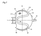
- FIG. 7 is a side view of the rotating member in FIG. 3.
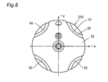
- FIG. 8 is a rear view of the rotating member in FIG. 3.
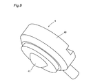
- FIG. 9 is a perspective view of the guide member in FIG. FIG.
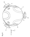
- FIG. 10 is a diagram illustrating an arrangement relationship between the rotating member and each guide member in the XYZ orthogonal coordinate system.
- FIG. 11 is a diagram illustrating the relationship between the XYZ orthogonal coordinate system and the UVW coordinate system.
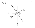
- FIG. 12 is another diagram showing the relationship between the XYZ orthogonal coordinate system and the UVW coordinate system.
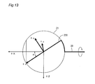
- FIG. 13 is a schematic diagram showing the relationship between the XYZ orthogonal coordinate system and the xyz orthogonal coordinate system when viewed in the + Y direction.
- FIG. 14 is a front view of the rotating member when the rotating member is disposed at the rotation start position.
- FIG. 15 is a view of the rotating member at the rotation start position as viewed from the ⁇ Z direction to the + Z direction.
- FIG. 16 is a view of FIG. 14 as viewed from a direction rotated 60 degrees clockwise around the X axis from the position of FIG.
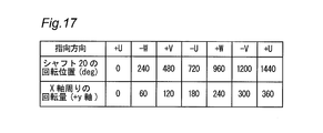
- FIG. 17 is a table showing the relationship between the rotational position of the shaft in FIG. 3 and the directing direction of the + y axis in FIG. 18 is a table showing the relationship between the rotational position of the shaft in FIG. 3 and the rotational direction around the + y axis in FIG.
- FIG. 19 is a functional block diagram showing a configuration of a control device provided in the azimuth detecting device in FIG.
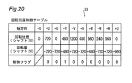
- FIG. 20 is a diagram illustrating an example of the rotational position control table in FIG.
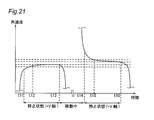
- FIG. 21 is a graph showing an example of the temporal change of the angular velocity output of the angular velocity sensor in FIG.
- FIG. 22 is a diagram illustrating another example of the temporal change in the angular velocity output of the angular velocity sensor in FIG.
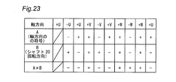
- FIG. 23 is a table showing the relationship between the rotation direction of the shaft in FIG. 3 and the symbols of the U axis, V axis, and W axis in FIG.
- FIG. 24 is a graph showing measurement results of rotation angular velocities around the U axis and the V axis in FIG.
- FIG. 25 is a flowchart of the control device in FIG.
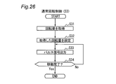
- FIG. 26 is a flowchart of the normal rotation control process in FIG.
- FIG. 27 is a flowchart of the excessive rotation control process in FIG.
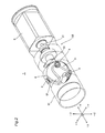
- FIG. 1 is an external view of an azimuth detecting device 1 according to the present embodiment.
- the direction detection device 1 includes a cylindrical housing 10.
- FIG. 2 is a perspective view showing a configuration inside the housing 10 in FIG. In FIG. 2, a part of the housing 10 is indicated by a one-dot chain line.
- azimuth detecting device 1 further includes posture changing device 100.
- the attitude changing device 100 is housed in a housing 10 and includes a drive source 3, an inclined crank mechanism 2, and a plurality of guide members 4.
- the drive source 3 and the plurality of guide members 4 are fixed to the housing 10.
- the drive source 3 is disposed at the rear part of the housing 10.
- the drive source 3 has a drive shaft 31 and rotates the drive shaft 31 around the central axis of the drive shaft 31.
- the drive source 3 is, for example, a motor.
- the type of motor is not particularly limited.
- the motor is, for example, a stepping motor or an ultrasonic motor.
- the azimuth detecting device 1 is installed in an XYZ orthogonal coordinate system. More specifically, the housing 10 is fixed to an XYZ orthogonal coordinate system.
- the XYZ orthogonal coordinate system is an orthogonal coordinate system in which the X, Y, and Z axes form 90 degrees with each other.
- the housing 10 assigns the X axis on the drive shaft 31 of the drive source 3.
- the + X direction is defined as the front side of the casing 10
- the ⁇ X direction is defined as the rear side of the casing 10.
- the Z axis is assigned to the vertical direction of the housing 10.
- the Y axis is assigned in the horizontal direction of the housing 10.
- the + Z direction is defined as the lower side of the casing 10
- the ⁇ Z direction is defined as the upper side of the casing 10.
- the + Y direction is defined as the left side when viewed from the front of the casing 10
- the ⁇ Y direction is defined as the right side when viewed from the front of the casing 10.
- the inclined crank mechanism 2 is disposed at the center of the housing 10.
- the inclined crank mechanism 2 is disposed in front of the drive source 3.
- FIG. 3 is a side view of the inclined crank mechanism 2 and the vicinity thereof in the azimuth detecting device 1 in FIG.
- a part of the housing 10 is indicated by a one-dot chain line.
- the inclined crank mechanism 2 includes a shaft 20 and a rotating member 21.
- the shaft 20 is rotated by the drive source 3.
- the rotating member 21 is coupled to the shaft 20 so as to be rotatable around an inclined axis 220 inclined with respect to the shaft 20.
- the rotating member 21 rotates around the inclined axis 220 while swinging up and down with respect to the X axis.
- the tilt axis 220 intersects the X axis at a tilt angle ⁇ degrees.
- the shaft 20 includes a rod-shaped main body 201 and an arm member 202.
- the main body 201 is disposed on the X axis.
- the rear end of the main body 201 is coupled to the drive shaft 31. Therefore, the main body 201 rotates around the central axis of the main body 201 by driving the drive source 3.
- An arm member 202 is disposed at the tip of the main body 201.
- the arm member 202 extends in a direction intersecting the X axis.
- the arm member 202 extends substantially perpendicular to the X axis, and the upper end portion is bent forward of the azimuth detecting device 1.
- the rear end of the arm member 202 is attached to the main body 201.
- the upper end portion of the arm member 202 is connected to the rotating member 21.
- the rotating member 21 is disposed in front of the shaft 20 and is connected to the shaft 20 via the arm member 202.
- the rotating member 21 includes a main body 210 and an inclined shaft 211.
- the main body 210 has a spherical shape and has a storage chamber 212 that opens forward.
- the inclined shaft 211 is arranged upright on the surface of the rotating member 21.
- the inclined shaft 211 is further disposed on the inclined axis 220.
- the upper end portion of the inclined shaft 211 is rotatably disposed in the boss of the arm member 202. Thereby, the rotating member 21 is attached so as to be rotatable around an inclined axis 220 inclined by ⁇ degrees with respect to the main body 201 of the shaft 20.
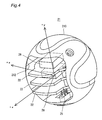
- FIG. 4 is a perspective view of the rotating member 21.
- rotating member 21 further includes a plurality of substrates 22, an angular velocity sensor 26, an acceleration sensor 28, and a position sensor 25.
- the plurality of substrates 22 are stored in the storage chamber 212.
- the plurality of substrates 22 are arranged with a gap in the vertical direction in FIG.
- the angular velocity sensor 26 is mounted on the uppermost substrate 22.
- the acceleration sensor 28 is mounted on the middle substrate 22.
- the arrangement location of the angular velocity sensor 26 and the acceleration sensor 28 is not particularly limited, and may be arranged on any substrate 22.
- the position sensor 25 is disposed on the lowermost substrate 22.
- the position sensor 25 includes a light transmitter and a light receiver. With reference to FIG. 3, a reflection plate 29 is disposed below the housing 10.
- the light transmitter in the position sensor 25 outputs light toward the outside of the rotating member 21.
- the rotating member 21 is moved (rotated) to a predetermined position by the drive source 3, the light emitted from the light transmitter is reflected by the reflecting plate 29.
- the position sensor 25 outputs a detection signal to the control device 30 described later.
- the azimuth detecting device 1 can recognize the rotation start position of the rotating member 21 by the position sensor 25.
- the rotating member 21 further has an xyz orthogonal coordinate system. Unlike the XYZ orthogonal coordinate system, the xyz orthogonal coordinate system is fixed to the rotating member 21. As shown in FIG. 4, in the present example, the + x direction faces the front of the rotating member 21. The + y direction coincides with the detection axis of the angular velocity sensor 26 and the detection axis of the acceleration sensor 28.
- the + y direction is directed to the plus and minus directions of the U axis, the V axis, and the W axis according to the rotation of the rotating member 21. Therefore, the angular velocity sensor 26 detects the angular velocity around the + y direction.
- the acceleration sensor 28 detects gravity acceleration in the + y direction.
- the xyz rectangular coordinate system is fixed to the rotating member 21.
- the XYZ orthogonal coordinate system is fixed to the housing 10. Therefore, if the rotating member 21 moves (rotates) with respect to the XYZ orthogonal coordinate system, the xyz orthogonal coordinate system also moves (rotates) with respect to the XYZ coordinate system.
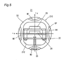
- FIG. 5 is a front view of the rotating member 21.
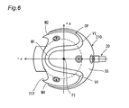
- FIG. 6 is a plan view of the rotating member 21.
- FIG. 7 is a side view of the rotating member 21.
- FIG. 8 is a rear view of the rotating member 21. 5 to 8, the main body 210 has a spherical surface SS.
- a track portion OP is formed on the spherical surface SS.
- the track portion OP is a groove formed in the spherical surface SS.
- the orbital portion OP has a plurality of peaks M1 to M4 that are formed around the x-axis and have protrusions in the + x direction, and a plurality of valleys V1 to V4 that have protrusions in the ⁇ x direction.
- the track portion OP is a zigzag groove extending around the x-axis.
- the opening of the storage chamber 212 has a rectangular shape, and the arrangement positions of the corners thereof correspond to the arrangement positions of the four valley portions V1 to V4. Thereby, the capacity
- FIG. 9 is a perspective view of the guide member 4.
- guide member 4 includes a pedestal 40 and a ball 41.
- the ball 41 is rotatably attached to the lower end of the pedestal 40.
- FIG. 10 is a diagram showing an arrangement relationship between the rotating member 21 and each guide member 4 in the XYZ orthogonal coordinate system.
- three guide members 4A to 4C are fixed to an XYZ orthogonal coordinate system.
- the guide members 4A to 4C are arranged at equal intervals around the X axis. In other words, the guide members 4A to 4C are arranged every 120 degrees around the X axis.
- the guide member 4A is disposed on the Z axis (+ Z direction side).
- the guide member 4B When the azimuth detecting device 1 is viewed from the front, the guide member 4B is disposed at a position rotated 120 degrees counterclockwise around the X axis from the guide member 4A, and the guide member 4C is disposed at a position rotated 240 degrees.
- the balls 41 of the guide members 4A to 4C are inserted into the groove-like track portion OP and come into contact with the track portion OP.
- the rotating member 21 is rotatably supported by the housing 10 by guide members 4A to 4C. When the rotating member 21 rotates, the ball 41 moves on the track portion OP. Therefore, how the rotating member 21 rotates depends on the shape of the track portion OP.
- the direction detection device 1 is installed in the XYZ orthogonal coordinate system.
- a UVW coordinate system is further assumed.
- 11 and 12 show the relationship between the XYZ rectangular coordinate system and the UVW rectangular coordinate system.
- 11 shows a YZ plan view as seen from the + X direction to the ⁇ X direction
- FIG. 12 shows a ZX plan view (right side view of FIG. 11) as seen from the ⁇ Y direction to the + Y direction.
- the elevation angle that the U, V, and W axes make with the YZ plane is ⁇ degrees. That is, the inclination angle ⁇ of the inclination shaft 220 with respect to the shaft 20 coincides with this elevation angle. Further, an intersection angle formed by the U, V, and W axes is ⁇ .
- the six axes + U, ⁇ U, + V, ⁇ V, + W, and ⁇ W are always arranged at intervals of 60 degrees on the YZ plane.
- the + U axis when the + U axis is projected perpendicularly to the YZ plane, it coincides with the ⁇ Z axis.
- the ⁇ U axis coincides with the + Z axis when projected perpendicular to the YZ plane.
- the ⁇ W axis forms 60 degrees with respect to the ⁇ Z axis when projected perpendicular to the YZ plane.
- the + W axis is projected perpendicularly to the YZ plane, it forms 60 degrees with respect to the + Z axis.
- the + V axis When the + V axis is projected perpendicularly to the YZ plane, it forms 60 degrees with respect to the + Z axis.
- the ⁇ V axis forms 60 degrees with respect to the ⁇ Z axis when projected perpendicular to the YZ plane.
- the dotted line axis indicates that it extends rearward from the paper surface of FIG. 11
- the solid line axis indicates the axis in FIG. It indicates that it extends to the front of the page.
- the intersection angle ⁇ is most preferably 90 degrees.
- the x axis on the + x side is referred to as “+ x axis”
- the x axis on the ⁇ x axis side is referred to as “ ⁇ x axis”.
- the other axes are defined in the same manner as in the case of the x axis.
- the definition is the same as in the case of the x-axis.
- the origins of the XYZ orthogonal coordinate system, the xyz orthogonal coordinate system, and the UVW orthogonal coordinate system are all the center points of the main body 210 of the rotating member 21.
- the azimuth detecting device 1 measures the rotational angular velocities ⁇ U , ⁇ V and ⁇ W around each axis of the UVW orthogonal coordinate system and the gravitational accelerations g U , g V and g W in the respective axis directions.
- the azimuth detecting device 1 uses the measured rotational angular velocities ⁇ U , ⁇ V , ⁇ W and the gravitational accelerations g U , g V , g W as the rotational angular velocities ⁇ X , ⁇ Y , ⁇ Z and the XYZ orthogonal coordinate system.
- the azimuth detecting device 1 calculates the azimuth angle ⁇ based on the rotation angular velocities ⁇ X , ⁇ Y , ⁇ Z and the gravitational accelerations g X , g Y , g Z.
- the angular velocity sensor 26 and the acceleration sensor 28 are swung only ⁇ ⁇ degrees with respect to the YZ plane. Therefore, the rotation angle is small and a larger space than that of the conventional azimuth measuring device is not required.
- the detection axes of the angular velocity sensor 26 and the acceleration sensor 28 are detected by the rotation of the rotating member 21.
- the orbit portion OP uses the + y axis of the rotating member 21 as the positive and negative directions of the U axis, the V axis, and the W axis. It has a shape that is directed sequentially.
- FIG. 13 is a schematic diagram showing the relationship between the XYZ orthogonal coordinate system and the xyz orthogonal coordinate system when viewed in the + Y direction.
- the x axis coincides with the tilt axis 220. Therefore, the angle formed by the x axis and the X axis is ⁇ degrees.
- the y axis is arranged on the XZ plane when the rotating member 21 is arranged at the position shown in FIG. Referring to FIGS. 12 and 13, when the rotating member 21 is disposed at the position shown in FIG.
- the + y axis coincides with the + U axis.
- the position shown in FIG. 13 is defined as the rotation start position of the rotating member 21.
- the position sensor 25 outputs a detection signal to the control device 30 (see FIG. 19) when the rotating member 21 moves to the position of FIG.
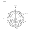
- FIG. 14 is a front view of the rotating member 21 when the rotating member 21 is disposed at the rotation start position, that is, a view seen from the + X direction to the ⁇ X direction.
- FIG. 15 is a view of the rotation member 21 at the rotation start position as viewed from the ⁇ Z direction to the + Z direction.
- FIG. 16 is a view of FIG. 14 as viewed from a direction rotated 60 degrees clockwise around the X axis from the position of FIG.
- the + y axis is shown in a bar shape. Referring to FIGS. 14 to 16, at the rotation start position, as described above, the + y axis coincides with the + U axis.
- the azimuth detecting device 1 is rotated by the rotation of the rotating member 21.
- the + y axis that coincides with the detection axes of the angular velocity sensor 26 and the acceleration sensor 28 needs to be directed in the plus and minus directions of the U axis, the V axis, and the W axis.
- the azimuth detecting device 1 directs the + y axis in the order of + U axis ⁇ ⁇ W axis ⁇ + V axis ⁇ ⁇ U axis ⁇ + W axis ⁇ ⁇ V axis ( ⁇ + U axis). .
- the + y axis moves in the order of path R1, path R2, path R3, path R4, path R5, path R6 ( ⁇ path R1).
- the order in which the + y axis is oriented in the plus and minus directions of the U, V, and W axes is not limited to the above order.
- the + y axis may be directed in the plus and minus directions of the U axis, the V axis, and the W axis in an order different from the above order.
- FIG. 17 is a table showing the relationship between the directing direction of the + y axis, the rotational position of the shaft 20, and the amount of rotation of the + y axis around the X axis.
- the rotation position of shaft 20 indicates a rotation angle when shaft 20 rotates counterclockwise around the X axis when viewed in the ⁇ X direction with reference to the rotation start position.
- the rotation position of the shaft 20 when the rotation member 21 is at the rotation start position is 0 degree.
- the + y axis is directed in the order of + U axis ⁇ ⁇ W axis ⁇ + V axis ⁇ ⁇ U axis ⁇ + W axis ⁇ ⁇ V axis ( ⁇ + U axis).
- the + y axis moves from the + U axis to the ⁇ W axis (see FIGS. 14 to 16).
- the + y axis rotates 60 degrees around the X axis.
- the + y axis moves along the trajectory R2, the trajectory R3, the trajectory R4, the trajectory R5, and the trajectory R6, the shaft 20 rotates 240 degrees, and the + y axis rotates 60 degrees around the X axis.
- the rotating member 21 rotates around the tilt axis 220 (x axis) according to the rotation of the shaft 20.
- the guide members 4A to 4C move on the track portion OP.
- the track part OP is a zigzag groove extending around the + x axis
- the rotating member 21 rotates around the + y axis as the guide members 4A to 4C move on the track part OP.
- the rotation around the + y axis means a rotational movement that rotates around the y axis as a central axis.
- the angular velocity sensor 26 outputs an angular velocity associated with the rotation around the + y axis.
- FIG. 18 is a table showing the correspondence between the rotational position of the shaft 20 and the rotational direction around the + y axis.
- the rotation direction “CW” around the + y axis indicates the clockwise direction when viewed in the ⁇ y direction
- “CCW” indicates the counterclockwise direction when viewed in the ⁇ y axis direction.
- the turning point is the rotational position of the shaft 20 when the rotational direction around the + y axis changes.
- the continuous rotation amount is the rotation amount of the shaft 20 required until the rotation direction around the + y axis changes next time.
- the rotating member 21 rotates counterclockwise around the + y axis as the shaft 20 rotates.
- the rotating member 21 continues to rotate the + y axis counterclockwise until the rotational position of the shaft 20 reaches the turning point (120 degrees) from the rotation start position.
- the rotation around the + y axis changes from counterclockwise to clockwise.
- the rotating member 21 continues to rotate clockwise around the + y axis until the + y axis is oriented in the ⁇ W axis direction.
- the rotating member 21 moves around the + y axis until the rotational position of the shaft 20 reaches the turning point (360 degrees).
- the rotation around the + y axis changes from clockwise to counterclockwise.
- the rotating member 21 continues to rotate counterclockwise around the + y axis until the + y axis is oriented in the + V axis direction.
- the rotational direction around the + y axis changes every time the rotational position of the shaft 20 reaches the turning point. That is, the rotation direction around the + y axis changes every time the shaft 20 rotates 240 degrees.
- the rotation direction around the + y axis is opposite to that in FIG.
- the + y axis is moved from the ⁇ W axis to the + U axis by rotating the shaft 20 clockwise, the + y axis first rotates counterclockwise (CCW). Thereafter, when the rotational position becomes smaller than the turning point (120 degrees), the rotation around the + y axis changes in the clockwise direction (CW).
- the rotation position (direction change point) of the shaft 20 where the rotation direction around the + y axis changes is 120, 360, 600, 840, 1080, and 1320 degrees.
- any one of the guide members 4A to 4C causes the + y axis and the spherical surface SS of the peak portions M1 to M4 and the valley portions V1 to V4 included in the track portion OP. Passes through a peak M1 located in the immediate vicinity of the intersection PI (see FIG. 6).
- the moving direction of the guide members 4A to 4C with respect to the rotating member 21 is reversed, so that the rotating direction around the + y axis changes.
- the detection axis (+ y axis) of the angular velocity sensor moves from a predetermined measurement direction (for example, + U axis) to another measurement direction (for example, ⁇ V axis)
- the detection axis (+ y axis) around the angular velocity sensor The direction of rotation will change.
- azimuth detecting device 1 further includes a control device 30 including a computer or the like.
- the control device 30 controls the posture change device 100.
- the control device 30 and the angular velocity sensor 26, the acceleration sensor 28, and the position sensor 25 in the rotating member 21 are connected by wire or wirelessly.
- the control device 30 includes a drive source control unit 32, a rotational position control table 33, a rotation angular velocity measurement unit 36, a gravity acceleration measurement unit 38, a rotation angular velocity coordinate conversion unit 42, a gravity acceleration coordinate conversion unit 46, an azimuth And an angle calculation unit 44.
- the drive source control unit 32 controls the drive source 3 based on the rotational position control table 33 in which the rotation amount of the shaft 20 is set.
- the rotational position control table 33 is stored in a storage device (not shown).
- the rotation angular velocity measuring unit 36 measures the angular velocities detected within a predetermined time by the angular velocity sensor 26 as the rotation angular velocities ⁇ U , ⁇ V and ⁇ W.
- the rotational angular velocities ⁇ U , ⁇ V, and ⁇ W are rotational angular velocity components around the respective axial directions of the U axis, the V axis, and the W axis.
- the gravitational acceleration measuring unit 38 measures the gravitational accelerations g U , g V and g W detected by the acceleration sensor 28.
- Gravitational accelerations g U , g V and g W are gravity acceleration components in the axial directions of the U axis, the V axis and the W axis, respectively.
- the rotation angular velocity coordinate conversion unit 42 converts the rotation angular velocity ⁇ U , ⁇ V and ⁇ W measured by the rotation angular velocity measurement unit 36 into the rotation angular velocity ⁇ X , ⁇ Y and ⁇ Z.
- the gravity acceleration coordinate conversion unit 46 converts the gravity accelerations g U , g V, and g W measured by the gravity acceleration measurement unit 38 into gravity accelerations g X , g Y, and g Z.
- the azimuth angle calculation unit 44 includes the rotation angular velocities ⁇ X , ⁇ Y, and ⁇ Z obtained by the rotation angular velocity coordinate conversion unit 42, and the gravitational accelerations g X , g Y, and g Z obtained by the gravitational acceleration coordinate conversion unit 46. Based on the above, the azimuth angle ⁇ is calculated.
- the rotation position control table 33 has an order in which the + y axis is directed in the plus and minus directions of the U axis, the V axis, and the W axis. Unlike the order shown in FIG. 16, the + y axis starts from the + U axis at the rotation start position, and is ⁇ U axis, + U axis, + V axis, ⁇ V axis, + V axis, + W axis, ⁇ W axis, + W axis, Directed in the order of + U axis.
- the rotation angular velocity ⁇ U is obtained by calculating a difference between the rotation angular velocity of the + U axis and the rotation angular velocity of the ⁇ U axis.
- the rotation angular velocity ⁇ V and the rotation angular velocity ⁇ W are obtained in the same manner. As a result, the bias inherent in the angular velocity sensor 26 is canceled.
- the angular velocity output of the angular velocity sensor 26 includes an offset unique to the angular velocity sensor 26.
- the offset changes with differences in operating conditions such as temperature, but also changes with drift.
- Drift refers to a phenomenon in which the offset increases (or decreases) over time.
- the azimuth detecting device 1 acquires the change rate of the offset due to the drift by measuring the + U axis twice before and after the measurement of the ⁇ U axis. The drift is removed from the measured angular velocity based on the obtained rate of change. The reason why the + V axis and the + W axis are measured twice is also the same.
- the reason why the rotational angular velocity of the + U axis is first measured and the rotational angular velocity of the + U axis is finally measured is to eliminate drift.
- the rotation angular velocity component at the rotation start position (+ U axis) at the end of the measurement it is possible to obtain the rate of change of the offset that occurs during a series of measurement periods necessary to obtain the azimuth angle ⁇ .
- the rotational position of the shaft 20 is the same as the rotational position shown in FIG. That is, the rotation position is a rotation angle of the shaft 20 necessary for directing the + y axis in the direction of each axis from the rotation start position.
- Rotation amount is the rotation angle of the shaft 20 when the + y axis is directed from the current axial direction to the next axial direction.
- the sign of the rotation amount indicates the rotation direction of the shaft 20, the sign “+” is the counterclockwise direction when viewed in the ⁇ X direction, and the sign “ ⁇ ” is the clockwise direction when viewed in the ⁇ X direction. is there.
- the rotation amount of the -U axis is set to +720 degrees. Therefore, when the + y axis is moved from the + U axis to the ⁇ U axis, the control device 30 rotates the shaft 20 720 degrees counterclockwise when viewed in the ⁇ X direction.
- the control flag indicates whether the control device 30 rotates the shaft 20 by normal rotation control or excessive rotation control. When the control flag is 0, execution of normal rotation control is indicated, and when the control flag is 1, execution of excessive rotation control is indicated. Details of the normal rotation control and the excessive rotation control will be described later.
- control device 30 that executes the normal rotation control will be described by taking as an example the case where the + y axis is moved from the + U axis to the ⁇ U axis.
- the description of the measurement of the gravitational acceleration is omitted unless otherwise described, but the gravitational acceleration is measured in parallel with the rotation angular velocity.
- control device 30 executes normal rotation control because the control flag of ⁇ U axis is set to 0.
- the normal rotation control is a process for rotating the shaft 20 by the rotation amount set in the rotation position control table 33.
- the control device 30 rotates the shaft 20 by the rotation amount (+720 degrees) set on the ⁇ U axis.
- the + y axis passes through the ⁇ W axis and the + V axis (see FIG. 14) and reaches the ⁇ U axis.
- control device 30 that executes the excessive rotation control will be described by taking the case where the + y axis moves from the + U axis to the + V axis as an example.
- the control device 30 executes the excessive rotation control and sets the + y axis because the control flag of the + V axis that is the next measurement target is set to 1. Move from + U axis to + V axis.
- +480 degrees is set as the rotation amount when moving from the + U axis to the + V axis.
- the control device 30 adds a preset excess amount (for example, 40 degrees) to +480 degrees, and calculates +520 degrees.
- the control device 30 rotates the shaft 20 520 degrees counterclockwise when viewed in the ⁇ X direction (excessive rotation).
- the + y axis passes through the ⁇ W axis and further passes through the + V axis once (see FIG. 14). That is, the + y axis moves halfway (between the + V axis and the ⁇ U axis) due to excessive rotation.
- the control device 30 further reversely rotates the shaft 20 rotated by +520 degrees by an excessive amount. Specifically, the control device 30 rotates the shaft 20 by 40 degrees clockwise as viewed in the ⁇ X direction.
- the + y-axis that has once passed through the + V-axis reaches the + V-axis by reversing the trajectory R3 by reverse rotation.
- control device 30 can not accurately measure the rotational angular velocity omega V.
- FIG. 21 shows the angular velocity detected by the angular velocity sensor 26 when the normal rotation control is executed during the movement of the + y axis from the + U axis to the + V axis and the movement of the + y axis from the + V axis to the ⁇ V axis. It is a graph which shows a time change.
- the control device 30 rotates the shaft 20 by +480 degrees.
- the + y axis reaches the + V axis while rotating around the + y axis.
- the angular velocity sensor 26 outputs an angular velocity associated with rotation around the y axis (hereinafter referred to as “moving angular velocity”) even during movement of the + y axis.
- the + y axis reaches the + V axis at time t11. Since the rotation direction around the + y axis immediately before reaching the + V axis is counterclockwise, the angular velocity sensor 26 outputs a negative angular velocity before time t11. The angular velocity output continues to increase after time t11 when the + y axis stops at the + V axis. This is because the moving angular velocity is included in the angular velocity output even after the y-axis is stopped due to the influence of the time constant of the angular velocity sensor 26.
- the angular velocity output during the period immediately after the + y axis stops at the + V axis varies greatly due to the influence of the time constant and is not stable.
- the control device 30 measures the angular velocity output of the angular velocity sensor 26 within a predetermined period (time t12 to t13) as the rotation angular velocity of the + V axis.
- the rotation angular velocity of the + V axis continues to increase slightly. That is, the rotation angular velocity of the + V axis includes an error associated with a time constant having a characteristic that increases with time.
- the + y axis moves from the + V axis to the ⁇ V axis (time t13 to t14).
- the + y axis rotates clockwise around the + y axis, so the angular velocity sensor 26 outputs a positive angular velocity immediately before time t14.
- the angular velocity output after time t14 when the + y axis stops at the ⁇ V axis continues to decrease due to the influence of the time constant.
- the -V-axis rotation angular velocity measured from time t15 to time t16 includes an error accompanying a time constant having a characteristic that decreases with time.
- the error characteristic associated with the time constant included in the ⁇ V-axis rotation angular velocity is opposite to the error characteristic associated with the time constant included in the + V-axis rotation angular velocity.
- the rotation angular velocity ⁇ V + of the + V axis and the rotation angular velocity ⁇ V ⁇ of the ⁇ V axis are expressed as follows.
- ⁇ V + True is a true rotation angular velocity that does not include the above-described error of the + V axis
- ⁇ V-True is a true rotation angular velocity of the ⁇ V axis.
- ⁇ V + True and ⁇ V-True have the same absolute value and different signs.
- V is an offset.
- ⁇ 1 is an error associated with a time constant included in the rotation angular velocity ⁇ V + of the + V axis.
- ⁇ 2 is an error accompanying a time constant included in the rotation angular velocity ⁇ V ⁇ .
- Rotational angular velocity omega V is obtained by subtracting the expression (2) from equation (1). The offset is canceled by the above subtraction.
- the error [delta] 1 of characteristics due to the time constant because when the error [delta] 2 of the characteristic opposite with a constant, the above subtraction, the error [delta] 2 with the time constant, the error [delta] 1 due to the time constant On the contrary, it is added to the error ⁇ 1 associated with the time constant without being canceled.
- Controller 30 can not accurately measure the rotational angular velocity omega V, it is impossible to accurately detect true north.
- control device 30 in order to reduce the errors associated with the time constant included in the rotational angular velocity omega V, when moving to the + V axis from the + U axis + y-axis, performing over-rotation control.
- the + y axis moves from the + V axis to the ⁇ V axis, normal rotation control is executed.
- FIG. 22 shows the time change of the angular velocity output of the angular velocity sensor 26 when the excessive rotation control is used for the movement from the + U axis to the + V axis and the normal rotation control is used for the movement from the + V axis to the ⁇ V axis. It is a graph to show.
- the control device 30 rotates the shaft 20 by an amount of rotation obtained by adding an excess amount (40 degrees) to +720 degrees (excess rotation).
- the + y axis once passes through the + V axis due to excessive rotation and stops in the middle of the locus R3.
- the rotation direction around the + y axis is counterclockwise.
- the control device 30 rotates the shaft 20 backward by 40 degrees to move the + y axis to the + V axis.
- the shaft 20 is rotated clockwise as viewed in the ⁇ X direction, the rotation direction around the + y axis is opposite to the rotation direction shown in FIG. Therefore, the rotation direction around the + y axis immediately before the + y axis reaches the + V axis is clockwise.
- the angular velocity sensor 26 outputs a positive moving angular velocity before time t21. After time t21 when the + y axis stops at the + V axis, the angular velocity output continues to decrease. As a result, the error ⁇ 1 associated with the time constant included in the rotation angular velocity of the + V axis has a characteristic that decreases with time.
- the + y axis moves from the + V axis to the ⁇ V axis by normal rotation control.
- the time change of the angular velocity output until the + y axis reaches the ⁇ V axis (until time t25), and the time change of the angular velocity output when stopped on the + V axis (after time t25) is after time t14 shown in FIG. It is the same as the time change of. That is, the error ⁇ 2 accompanying the time constant included in the ⁇ V axis rotation angular velocity has a characteristic of decreasing with time.
- the error ⁇ 1 associated with the time constant included in the rotation angular velocity of the + V axis has the same characteristics as the error ⁇ 2 associated with the time constant included in the rotation angular velocity of the ⁇ V axis. Therefore, in order to obtain the rotational angular velocity ⁇ V (the axial rotational angular velocity along the + V direction and the ⁇ V direction), when the equation (2) is subtracted from the equation (1), the error ⁇ 1 associated with the time constant is It cancels out the error ⁇ 2 associated with the time constant. In rotational angular speed omega V, because it is possible to suppress the effect of the errors associated with the time constant, thereby improving the detection accuracy of the true north.
- FIG. 23 is a table showing the relationship between the rotation direction of the shaft 20 and the signs of the U, V, and W axes.
- A indicates the symbols of the U axis, V axis, and W axis.
- the signs of + U axis, + V axis and + W are positive.
- the sign of the ⁇ U axis, ⁇ V axis or ⁇ W axis is negative.
- B indicates the rotation direction of the shaft 20 when the shaft 20 is rotated based on the rotation position control table 33.
- B When the shaft 20 rotates clockwise as viewed in the ⁇ X direction, B is set to minus, and when the shaft 20 rotates counterclockwise as viewed in the ⁇ X direction, B is set to plus.
- a ⁇ B is the product of the U-axis, V-axis, and W-axis codes (A) and the shaft 20 rotation direction code (B).
- a ⁇ B is referred to as “code product” for convenience.
- the code product corresponds to the rotation direction around the + y axis immediately before the + y axis stops at each axis.
- the code product is positive, the rotation direction around the y-axis immediately before stopping at each axis is counterclockwise.
- the code product is negative, the rotation direction around the y-axis immediately before stopping at each axis is clockwise.
- the control device 30 may determine the target of excessive rotation control so that the number of executions of normal rotation control is greater than the number of executions of excessive rotation control.
- the control device 30 executes normal rotation control when moving from the + V axis to the ⁇ V axis and from the ⁇ V axis to the + V axis, and excessively rotates when moving from the + U axis to the + V axis. Execute control. By suppressing the number of times of excessive rotation control, the measurement time of the rotation angular velocity of each axis can be shortened.
- the code products A ⁇ B are aligned with minus, and in the case of the W axis, the code products A ⁇ B are aligned with plus. Therefore, when measuring the rotation angular velocity ⁇ U and the rotation angular velocity ⁇ W , the control device 30 only needs to perform normal rotation control.
- the target of excessive rotation control may be determined so that the code products of all axes match.
- the positive number is smaller than the negative number. Therefore, when the code product A ⁇ B is set to minus, the movement from the + U axis to the ⁇ U axis, the movement from the ⁇ U axis to the + U axis, the movement from the + V axis to the ⁇ V axis, and the movement from the ⁇ V axis to the + V axis.
- excessive rotation control may be executed.
- the control device 30 performs the normal rotation control so that the angular velocity sensor 26 rotates around the detection axis (+ y axis) in the first rotation direction before the angular velocity sensor 26 starts measuring the angular velocity around the predetermined measurement direction.
- the posture changing device 100 is controlled to rotate. Before the angular velocity sensor 26 starts measuring the angular velocity around the direction opposite to the predetermined measurement direction, the control device 30 controls the angular velocity sensor 26 around the detection axis (+ y axis) as the first rotational direction by over-rotation control.
- the posture changing device 100 is controlled so as to rotate in the opposite second rotation direction and the angular velocity sensor 26 further rotates around the detection axis (+ y axis) in the first rotation direction.
- FIG. 24 is a graph showing the rotation angular velocity measurement results when only normal rotation control is used and when excessive rotation control is used in addition to normal rotation control.
- the graph of FIG. 24 shows the result of measuring the rotational angular velocity of each axis according to the order specified in the rotational position control table 33 shown in FIG.
- Rotational angular velocity when combined with excessive rotation control is generally smaller than the rotational angular velocity when only normal rotation control is used.
- the reason for this is that the error associated with the time constant is not offset when using only normal rotation control, but is added to the rotational angular velocity, whereas it is offset when using excessive rotation control. It is. It can be seen that the measurement accuracy of the rotation angular velocity can be improved by using the excessive rotation control.
- the variation of the rotation angular velocity when using the excessive rotation control is smaller than the variation of the rotation angular velocity when using only the normal rotation control.
- Variations in the rotational angular velocity are caused by errors associated with time constants. It can be seen that the variation in the rotation angular velocity is suppressed by canceling out the error due to the time constant by the excessive rotation control.
- FIG. 25 is a flowchart of the control device 30.
- control device 30 specifies the next directing direction of + y axis based on the current position of + y axis and rotation position control table 33 (step S ⁇ b> 1).
- the control device 30 determines whether or not to perform excessive rotation control when moving the + y axis in the next axial direction (step S2). Specifically, the control device 30 refers to the rotation position control table 33 and executes normal rotation control when the control flag corresponding to the next axial direction is set to 0 (No in step S2). (Step S3). For example, referring to FIG. 20, when the next axial direction is the ⁇ U axis, control device 30 executes normal rotation control because the control flag for ⁇ U axis is set to 0.
- step S4 when the control flag for the next axial direction is set to “1” (Yes in step S2), the control device 30 executes the excessive rotation control (step S4).
- the control flag of the control device 30 when the current position of the + y axis is the + U axis and the next stop position is the + V axis, the control flag of the control device 30 is set to “1”. Therefore, excessive rotation control is executed.
- FIG. 26 is a flowchart of normal rotation control (step S3).
- control device 30 acquires a rotation amount corresponding to the next axial direction from rotation position control table 33 (step S31), and sets the acquired rotation amount as the rotation amount of shaft 20 (step S31). S32).
- the control device 30 outputs a pulse signal corresponding to the acquired rotation amount to the drive source 3 (step S33).
- the control device 30 ends the normal rotation control.
- FIG. 27 is a flowchart of excessive rotation control (step S4).
- control device 30 acquires a rotation amount corresponding to the next stop position from rotation position control table 33 (step S41).
- the drive source control unit 32 sets the rotation amount of the shaft 20 excessively by adding a preset excessive amount (40 degrees) to the acquired rotation amount (step S42).
- a preset excessive amount 40 degrees
- the rotation amount of the shaft 20 is set by adding the excessive rotation amount to the acquired rotation amount.
- the sign of the acquired rotation amount is negative, the rotation amount of the shaft 20 is set excessively by subtracting the excessive rotation amount from the acquired rotation amount.
- Control device 30 outputs a pulse signal corresponding to the set rotation amount to drive source 3 (step S43). As a result, the + y axis once passes the next axial direction.
- Step S45 When the rotational movement amount of the shaft 20 reaches an excessively set rotational amount (Yes in Step S44), the control device 30 sets the excessive amount as the rotational amount of the shaft 20 (Step S45).
- the rotation direction is set in the reverse direction based on the sign of the rotation amount acquired in step S41.
- the control device 30 outputs a pulse signal corresponding to the set rotation amount to the drive source 3 (step S46).
- the pulse signal is output to the drive source 3 until the rotation amount of the shaft 20 reaches the set rotation amount (Yes in step S46).
- the + y axis stops in the designated next axial direction.
- the bearing detection device 1 executes normal rotation control or excessive rotation control.
- the rotational directions around the y axis immediately before the + y axis reaches the positive, negative directions of the U, V, and W axes can be matched.
- errors due to the time constant can be canceled out, so that the detection accuracy of the azimuth angle ⁇ can be improved.
- a biaxial or triaxial azimuth detecting device may perform normal rotation control and excessive rotation control.
- a three-axis type azimuth detecting device including an X-axis angular velocity sensor, a Y-axis angular velocity sensor, and a Z-axis angular velocity sensor.
- the three-axis type azimuth detecting device measures the + X-axis rotation angular velocity and the -X-axis rotation angular velocity by rotating the X-axis angular velocity sensor around the Y-axis. At this time, the angular velocity sensor for the Y axis rotates around the Y axis.
- the rotational direction of the angular velocity sensor for the Y axis may be set immediately before measuring the rotational angular velocity of the + Y axis and the rotational angular velocity of the -Y axis. The situation may be reversed immediately before the measurement.
- the three-axis type azimuth detecting device executes excessive rotation control before starting measurement of the rotation angular velocity of the + Y axis.
- the rotation direction of the rotation angular velocity sensor for the Y axis can be aligned between immediately before measuring the rotation angular velocity of the + Y axis and immediately before measuring the rotation angular velocity of the ⁇ Y axis. Measurement accuracy can be improved.
- each functional block of the control device 30 may be individually made into one chip by a semiconductor device such as an LSI, or may be made into one chip so as to include a part or all of it.
- the method of circuit integration is not limited to LSI, and implementation with a dedicated circuit or a general-purpose processor is also possible.
- An FPGA Field Programmable Gate Array
- a reconfigurable processor that can reconfigure the connection and setting of circuit cells inside the LSI may be used.
- part or all of the processing of each functional block described above may be realized by a program.
- a part or all of the processing of each functional block in each of the above embodiments is performed by a central processing unit (CPU) in the computer.
- a program for performing each processing is stored in a storage device such as a hard disk or a ROM, and is read out and executed in the ROM or the RAM. Further, these programs may be provided by being stored in a recording medium such as a CD or a DVD.
- each processing of the above embodiment may be realized by hardware, or may be realized by software (including a case where it is realized together with an OS (operating system), middleware, or a predetermined library). Further, it may be realized by mixed processing of software and hardware. Needless to say, when the control device 30 according to the above-described embodiment is realized by hardware, it is necessary to perform timing adjustment for performing each process. In the above embodiment, for convenience of explanation, details of timing adjustment of various signals generated in actual hardware design are omitted.
Landscapes
- Physics & Mathematics (AREA)
- Engineering & Computer Science (AREA)
- General Physics & Mathematics (AREA)
- Radar, Positioning & Navigation (AREA)
- Remote Sensing (AREA)
- Life Sciences & Earth Sciences (AREA)
- Environmental & Geological Engineering (AREA)
- General Life Sciences & Earth Sciences (AREA)
- Geology (AREA)
- Gyroscopes (AREA)
Abstract
Description
図1は本実施の形態における方位検出装置1の外観図である。方位検出装置1は、筒状の筐体10を備える。
図3は、図2中の方位検出装置1のうち、傾斜クランク機構2とその近傍の側面図である。図3では、筐体10の一部を1点鎖線で示す。図3を参照して、傾斜クランク機構2は、シャフト20と、回転部材21とを備える。
回転部材21は、シャフト20の前方に配置され、アーム部材202を介してシャフト20と連結される。回転部材21は、本体210と、傾斜シャフト211とを備える。本体210は球状であり、前方が開口する収納室212を有する。傾斜シャフト211は、回転部材21の表面に立てて配置される。傾斜シャフト211はさらに、傾斜軸220上に配置される。傾斜シャフト211の上端部は、アーム部材202のボス内に回転可能に配置される。これにより、回転部材21は、シャフト20の本体201に対してα度傾斜した傾斜軸220の周りを回転可能に取り付けられる。
上述のとおり、方位検出装置1はXYZ直交座標系内に設置される。本実施の形態ではさらに、UVW座標系を想定する。XYZ直交座標系とUVW直交座標系との関係を図11及び図12に示す。図11は+X方向から-X方向に見たYZ平面図を示し、図12は-Y方向から+Y方向に見たZX平面図(図11の右側面図)を示す。U、V、W軸がYZ平面となす仰角をα度とする。つまり、シャフト20に対する傾斜軸220の傾斜角αは、この仰角と一致する。さらに、U,V,W軸が互いになす交角をβとする。
方位検出装置1は、UVW直交座標系の各軸周りの自転角速度ωU、ωV及びωWと、各軸方向の重力加速度gU、gV及びgWとを計測する。次に、方位検出装置1は、計測された自転角速度ωU、ωV、ωW及び重力加速度gU、gV、gWをXYZ直交座標系における自転角速度ωX、ωY、ωZ及び重力加速度gX、gY、gZに座標変換する。次に、方位検出装置1は、自転角速度ωX、ωY、ωZ及び重力加速度gX、gY、gZに基づいて方位角ψを算出する。方位検出装置1では、角速度センサ26及び加速度センサ28はYZ平面に対して±α度しか揺動されない。そのため、回転角度が小さく、従来の方位測定装置よりも大きな空間を必要としない。
初めに、回転部材21が回転したときの+y軸の軌跡を説明する。
+y軸がU軸、V軸及びW軸の各プラス及びマイナス方向に向けて移動する間、回転部材21は、+y軸周りを回転する。
図19を参照して、方位検出装置1はさらに、コンピュータ等からなる制御装置30を備える。制御装置30は、姿勢変更装置100を制御する。制御装置30と回転部材21内の角速度センサ26、加速度センサ28及び位置センサ25とは、有線又は無線で接続されている。
図20を参照して、回転位置制御テーブル33には、+y軸をU軸、V軸及びW軸の各プラス及びマイナス方向に向ける順序が設定されている。+y軸は、図16に示す順序と異なり、回転開始位置の+U軸からスタートして、-U軸、+U軸、+V軸、-V軸、+V軸、+W軸、-W軸、+W軸、+U軸の順に指向する。+y軸が+U軸に一致しているときのシャフトの位置が、シャフト20の回転開始位置(回転角=0度)となる。
+y軸を各軸方向に向ける際の制御装置30の基本的な動作を説明する。
ωV-=ωV-True+V+δ2 ・・・(2)
図25は、制御装置30のフローチャートである。図25を参照して、制御装置30は、+y軸の現在位置と、回転位置制御テーブル33とに基づいて、+y軸の次の指向方向を特定する(ステップS1)。
Claims (6)
- 角速度センサと、
前記角速度センサを検出軸周りに回転させ、前記検出軸を所定の測定方向と前記所定の測定方向と反対の方向とに向けるように前記角速度センサの姿勢を変更する姿勢変更装置と、
前記姿勢変更装置を制御する制御装置と、
を備え、
前記制御装置は、
前記角速度センサが前記所定の測定方向周りの角速度の検出を開始する前に、前記角速度センサが前記検出軸周りを第1回転方向に回転するように前記姿勢変更装置を制御する第1制御部と、
前記角速度センサが前記反対の方向周りの角速度の検出を開始する前に、前記角速度センサが前記検出軸周りを前記第1回転方向と反対の第2回転方向に回転し、前記角速度センサが前記検出軸周りをさらに前記第1回転方向に回転するように前記姿勢変更装置を制御する第2制御部とを備える、方位検出装置。 - 請求項1に記載の方位検出装置であって、
前記制御装置は、前記角速度センサにより検出された前記所定の測定方向周りの角速度と、前記角速度センサにより検出された前記反対の方向周りの角速度との差分を計算して、前記所定の測定方向に沿った軸周りの自転角速度を取得する、方位検出装置。 - 請求項1又は2に記載の方位検出装置であって、
前記姿勢変更装置は、XYZ直交座標系内に設置され、
前記姿勢変更装置は、
X軸方向に延びたシャフトと、
前記シャフトに対してα度傾斜した傾斜軸周りを回転可能であり、前記シャフトと連結され、xyz直交動座標系を有し、球体状表面と、前記球体状表面のx軸周りに形成された軌道部とを備える回転部材と、
前記制御装置により制御され、前記シャフトをX軸周りに回転する駆動源と、
前記XYZ直交座標系に固定され、前記軌道部と接触するガイド部材とを備え、
前記軌道部は、前記シャフトの回転により前記ガイド部材と接触しながら回転するときに、前記回転部材のy軸を、X軸周りの60度おきに互いに交わるU軸、V軸及びW軸のプラス及びマイナス方向に順次向ける形状を有し、x軸のプラス方向に凸状の4つの山部と、マイナス方向に凸状の4つの谷部とを有するジグザグ状であり、
前記角速度センサは、前記検出軸がy軸を向くように前記回転部材に取り付けられ、
所定の測定方向及び反対の方向は、U軸、V軸及びW軸のいずれか1つに一致する、方位検出装置。 - 請求項3に記載の方位検出装置であって、
前記制御装置は、前記角速度センサがU軸、V軸及びW軸のいずれか1つの軸方向周りの角速度を検出する場合、前記検出軸が前記いずれか1つの軸のプラス方向、マイナス方向、プラス方向の順に向けられるように、前記姿勢変更装置を制御し、
前記角速度センサが前記いずれか1つの軸方向周りの角速度を検出する際に、前記第2制御部により制御される回数が、前記第1制御部により制御される回数よりも少ない、方位検出装置。 - 請求項3又は4に記載の方位検出装置であって、
前記検出軸がU軸、V軸及びW軸のいずれか1つの軸のプラス方向に向けられる場合、前記検出軸の符号がプラスであり、前記検出軸がU軸、V軸及びW軸のいずれかの1つ軸のマイナス方向に向けられる場合、前記検出軸の符号がマイナスであり、
前記シャフトが前記方位検出装置の正面から見て時計回りに回転する場合、前記シャフトの回転方向の符号がプラスであり、前記シャフトが反時計回りに回転する場合、前記シャフトの回転方向の符号がマイナスであり、
前記検出軸が前記いずれか1つの軸のプラス方向、マイナス方向に向けられる場合、前記姿勢変更装置が前記第1制御部により制御されるか否かが、前記検出軸の符号と前記回転方向の符号との積に基づいて決定される、方位検出装置。 - 検出軸周りの角速度を検出する角速度センサと、前記角速度センサを前記検出軸周りに回転させ、前記検出軸を所定の測定方向と前記所定の測定方向と反対の方向に向けるように前記角速度センサの姿勢を変更する姿勢変更装置とを備える方位検出装置に搭載されるコンピュータに、
前記角速度センサが前記所定の測定方向周りの角速度の検出を開始する前に、前記角速度センサが検出軸周りを第1回転方向に回転するように前記姿勢変更装置を制御するステップと、
前記角速度センサが前記反対の方向周りの角速度の検出を開始する前に、前記角速度センサが前記検出軸周りを前記第1回転方向と反対の第2回転方向に回転し、前記角速度センサが前記検出軸周りをさらに前記第1回転方向に回転するように前記姿勢変更装置を制御するステップとを実行させるための制御プログラム。
Priority Applications (2)
| Application Number | Priority Date | Filing Date | Title |
|---|---|---|---|
| JP2015508132A JP6250031B2 (ja) | 2013-03-29 | 2014-01-30 | 方位検出装置 |
| US14/776,738 US9441968B2 (en) | 2013-03-29 | 2014-01-30 | Direction detector |
Applications Claiming Priority (2)
| Application Number | Priority Date | Filing Date | Title |
|---|---|---|---|
| JP2013-071378 | 2013-03-29 | ||
| JP2013071378 | 2013-03-29 |
Publications (1)
| Publication Number | Publication Date |
|---|---|
| WO2014156288A1 true WO2014156288A1 (ja) | 2014-10-02 |
Family
ID=51623290
Family Applications (1)
| Application Number | Title | Priority Date | Filing Date |
|---|---|---|---|
| PCT/JP2014/052133 Ceased WO2014156288A1 (ja) | 2013-03-29 | 2014-01-30 | 方位検出装置 |
Country Status (3)
| Country | Link |
|---|---|
| US (1) | US9441968B2 (ja) |
| JP (1) | JP6250031B2 (ja) |
| WO (1) | WO2014156288A1 (ja) |
Citations (3)
| Publication number | Priority date | Publication date | Assignee | Title |
|---|---|---|---|---|
| JPH04142088A (ja) * | 1990-10-02 | 1992-05-15 | Tokimec Inc | レイトバイアス装置 |
| JPH08210855A (ja) * | 1995-02-01 | 1996-08-20 | Japan Aviation Electron Ind Ltd | 方位測定装置 |
| JP2012112679A (ja) * | 2010-11-19 | 2012-06-14 | Sumitomo Precision Prod Co Ltd | 6方向指向装置 |
-
2014
- 2014-01-30 JP JP2015508132A patent/JP6250031B2/ja active Active
- 2014-01-30 US US14/776,738 patent/US9441968B2/en active Active
- 2014-01-30 WO PCT/JP2014/052133 patent/WO2014156288A1/ja not_active Ceased
Patent Citations (3)
| Publication number | Priority date | Publication date | Assignee | Title |
|---|---|---|---|---|
| JPH04142088A (ja) * | 1990-10-02 | 1992-05-15 | Tokimec Inc | レイトバイアス装置 |
| JPH08210855A (ja) * | 1995-02-01 | 1996-08-20 | Japan Aviation Electron Ind Ltd | 方位測定装置 |
| JP2012112679A (ja) * | 2010-11-19 | 2012-06-14 | Sumitomo Precision Prod Co Ltd | 6方向指向装置 |
Also Published As
| Publication number | Publication date |
|---|---|
| JPWO2014156288A1 (ja) | 2017-02-16 |
| US9441968B2 (en) | 2016-09-13 |
| JP6250031B2 (ja) | 2017-12-20 |
| US20160033271A1 (en) | 2016-02-04 |
Similar Documents
| Publication | Publication Date | Title |
|---|---|---|
| JP5749919B2 (ja) | 6方向指向装置 | |
| US9476709B2 (en) | Calibration apparatus, calibration method, and manufacturing method for an electronic device | |
| JP5377507B2 (ja) | 6方向指向装置 | |
| KR20170094851A (ko) | 기울기센서를 이용한 자이로센서의 캘리브레이션 방법 | |
| US20190219393A1 (en) | Three-dimensional surveying device and three-dimensional surveying method | |
| JP6250031B2 (ja) | 方位検出装置 | |
| JP2004125511A (ja) | ジャイロ装置及び掘削用ジャイロ装置の使用方法 | |
| CN114502983A (zh) | 利用激光的测距装置及测距方法 | |
| CN107923752A (zh) | 具有用于翻转测量的转台的导航设备和操作此导航设备的方法 | |
| JPH098533A (ja) | アンテナ姿勢制御装置 | |
| CN113167585B (zh) | 惯性测量装置 | |
| US11592911B2 (en) | Predictive data-reconstruction system and method for a pointing electronic device | |
| JP4938496B2 (ja) | 方位計測装置及びその方法 | |
| JP2007033401A (ja) | 衛星追尾用のアンテナ制御装置 | |
| JPH07271435A (ja) | 走行ロボット | |
| JPH01188254A (ja) | 非接触倣いデジタイジング方法 | |
| JP2022158099A (ja) | 反転作動型慣性検出装置及び測量装置 | |
| TWI895835B (zh) | 移動型機器人精度量測定向輔助模組 | |
| JP2016031283A (ja) | 角速度センサ装置および角速度センサ補正方法 | |
| CN120121044B (zh) | 一种小型化单轴旋转调制惯导系统及其转位方法 | |
| Estrada | INDOOR ROBOT MOBILE POSITIONING BY RANGE AND BEARING MEASUREMENTS | |
| KR20250094257A (ko) | 센서 모듈 및 이를 포함하는 전자 장치 | |
| CA3253655A1 (en) | CALIBRATION OF THE SENSOR INSTALLATION FOR MONITORING SIX-SETTING BLADES |
Legal Events
| Date | Code | Title | Description |
|---|---|---|---|
| 121 | Ep: the epo has been informed by wipo that ep was designated in this application |
Ref document number: 14775680 Country of ref document: EP Kind code of ref document: A1 |
|
| ENP | Entry into the national phase |
Ref document number: 2015508132 Country of ref document: JP Kind code of ref document: A |
|
| WWE | Wipo information: entry into national phase |
Ref document number: 14776738 Country of ref document: US |
|
| NENP | Non-entry into the national phase |
Ref country code: DE |
|
| 122 | Ep: pct application non-entry in european phase |
Ref document number: 14775680 Country of ref document: EP Kind code of ref document: A1 |