WO2014156172A1 - オイルレシーバー及び変速機 - Google Patents
オイルレシーバー及び変速機 Download PDFInfo
- Publication number
- WO2014156172A1 WO2014156172A1 PCT/JP2014/001798 JP2014001798W WO2014156172A1 WO 2014156172 A1 WO2014156172 A1 WO 2014156172A1 JP 2014001798 W JP2014001798 W JP 2014001798W WO 2014156172 A1 WO2014156172 A1 WO 2014156172A1
- Authority
- WO
- WIPO (PCT)
- Prior art keywords
- case
- rotation center
- shaft
- oil receiver
- idler
- Prior art date
- Legal status (The legal status is an assumption and is not a legal conclusion. Google has not performed a legal analysis and makes no representation as to the accuracy of the status listed.)
- Ceased
Links
Images
Classifications
-
- F—MECHANICAL ENGINEERING; LIGHTING; HEATING; WEAPONS; BLASTING
- F16—ENGINEERING ELEMENTS AND UNITS; GENERAL MEASURES FOR PRODUCING AND MAINTAINING EFFECTIVE FUNCTIONING OF MACHINES OR INSTALLATIONS; THERMAL INSULATION IN GENERAL
- F16H—GEARING
- F16H57/00—General details of gearing
- F16H57/02—Gearboxes; Mounting gearing therein
- F16H57/021—Shaft support structures, e.g. partition walls, bearing eyes, casing walls or covers with bearings
-
- F—MECHANICAL ENGINEERING; LIGHTING; HEATING; WEAPONS; BLASTING
- F16—ENGINEERING ELEMENTS AND UNITS; GENERAL MEASURES FOR PRODUCING AND MAINTAINING EFFECTIVE FUNCTIONING OF MACHINES OR INSTALLATIONS; THERMAL INSULATION IN GENERAL
- F16H—GEARING
- F16H57/00—General details of gearing
- F16H57/04—Features relating to lubrication or cooling or heating
- F16H57/042—Guidance of lubricant
- F16H57/0421—Guidance of lubricant on or within the casing, e.g. shields or baffles for collecting lubricant, tubes, pipes, grooves, channels or the like
- F16H57/0423—Lubricant guiding means mounted or supported on the casing, e.g. shields or baffles for collecting lubricant, tubes or pipes
-
- F—MECHANICAL ENGINEERING; LIGHTING; HEATING; WEAPONS; BLASTING
- F16—ENGINEERING ELEMENTS AND UNITS; GENERAL MEASURES FOR PRODUCING AND MAINTAINING EFFECTIVE FUNCTIONING OF MACHINES OR INSTALLATIONS; THERMAL INSULATION IN GENERAL
- F16H—GEARING
- F16H57/00—General details of gearing
- F16H57/04—Features relating to lubrication or cooling or heating
- F16H57/048—Type of gearings to be lubricated, cooled or heated
- F16H57/0493—Gearings with spur or bevel gears
- F16H57/0494—Gearings with spur or bevel gears with variable gear ratio or for reversing rotary motion
-
- F—MECHANICAL ENGINEERING; LIGHTING; HEATING; WEAPONS; BLASTING
- F16—ENGINEERING ELEMENTS AND UNITS; GENERAL MEASURES FOR PRODUCING AND MAINTAINING EFFECTIVE FUNCTIONING OF MACHINES OR INSTALLATIONS; THERMAL INSULATION IN GENERAL
- F16H—GEARING
- F16H3/00—Toothed gearings for conveying rotary motion with variable gear ratio or for reversing rotary motion
- F16H3/02—Toothed gearings for conveying rotary motion with variable gear ratio or for reversing rotary motion without gears having orbital motion
- F16H3/08—Toothed gearings for conveying rotary motion with variable gear ratio or for reversing rotary motion without gears having orbital motion exclusively or essentially with continuously meshing gears, that can be disengaged from their shafts
- F16H2003/0822—Toothed gearings for conveying rotary motion with variable gear ratio or for reversing rotary motion without gears having orbital motion exclusively or essentially with continuously meshing gears, that can be disengaged from their shafts characterised by the arrangement of at least one reverse gear
-
- F—MECHANICAL ENGINEERING; LIGHTING; HEATING; WEAPONS; BLASTING
- F16—ENGINEERING ELEMENTS AND UNITS; GENERAL MEASURES FOR PRODUCING AND MAINTAINING EFFECTIVE FUNCTIONING OF MACHINES OR INSTALLATIONS; THERMAL INSULATION IN GENERAL
- F16H—GEARING
- F16H57/00—General details of gearing
- F16H57/02—Gearboxes; Mounting gearing therein
- F16H2057/02013—Extension units for gearboxes, e.g. additional units attached to a main gear
Definitions
- the present invention relates to an oil receiver and a transmission.
- Patent Literature 1 and Patent Literature 2 include transmissions that change the power input from the power source in accordance with the vehicle speed and output the power to the drive wheels.
- the transmissions of Patent Document 1 and Patent Document 2 have a rotation center shaft (input shaft) in which a plurality of rolling members (gears, clutch hubs, etc.) are attached to one of cases that can be divided into a plurality of cases. , One end of the output shaft, etc.) is inserted and the remaining cases are covered, and the cases are fixed to each other, or the case and the rotation center shaft are fixed to form one case.
- a rotation center shaft input shaft
- a plurality of rolling members gears, clutch hubs, etc.
- the transmission shown in FIG. 1 of Patent Document 1 and FIG. 1 of Patent Document 2 two of the three rotation center shafts have both ends inserted into the case, and one has one end inserted into the case. Yes. Therefore, it is common to assemble with the side where the three rotation center shafts are inserted facing down.
- the side on which the two rotation center shafts are inserted may be assembled downward.
- the position of the rotation center shaft not inserted in the lower case is maintained by some method, and is assembled by covering another case.
- a jig, a robot, or the like In order to hold the position of the rotation center axis that is not inserted into the case, if it is supported from the outside of the case by a hand, a jig, a robot, or the like, what is held to cover another case becomes an obstacle. If a member for holding inside is arranged, unnecessary members remain in the transmission after assembly.
- JP 2012-154444 A see FIG. 1
- JP 2012-163178 A see FIG. 1
- the present invention has been made in view of the above situation, and when assembling one of the cases divided into a plurality of cases downward, an oil receiver and a transmission for holding a rotation center shaft that is not held with respect to the case. Providing a machine is an issue to be solved.
- the structural features of the invention for solving the above problems are a case that can be divided into a plurality of cases, A plurality of rotation center shafts pivotally supported by the case;
- An oil receiver used for a transmission having a plurality of rolling members rotatably attached to the plurality of rotation center shafts, A first case that is one of the cases in the axial direction of the rotation center axis, and a first rotation center axis that is one of the rotation center axes and does not contact the first case;
- a shaft support portion that is positioned between and supports one of the first rotation center shafts;
- a receiving portion located between the shaft support portion and the first case, wherein one of the first rotation center shafts abuts on the first case, and receives the lubricating oil in the transmission;
- One of the first rotation center shafts is in contact with the first case, and the holding portion is located between the shaft support portion and the first case on the side opposite to the receiving portion receiving the lubricating oil.
- the invention of the above (1) can be adopted by arbitrarily adding one or more of the following configurations (2) to (4).
- the invention of (2) is that the holding portion is in contact with the shaft support portion on the other side of the first rotation center shaft.
- the invention of (3) includes a lubricating oil passage in which the first rotation center axis is formed in the axial direction inside, A discharge portion for discharging the lubricating oil received by the receiving portion; The discharge part and the lubricating oil passage communicate with each other.
- the other one of the first rotation center shafts is pivotally supported by a second case in which the first rotation center shaft is one of the cases that can be divided into a plurality of cases. That is.
- the invention of (5) is a transmission having the oil receiver described in any one of (1) to (4).
- the first rotation center shaft does not contact the first case, and the oil receiver contacts the first case.
- the oil receiver is located between the first rotation center axis and the first case.
- the oil receiver is in contact with the first rotation center shaft at the shaft support portion, and the receiving portion and the holding portion are in contact with the first case. That is, the oil receiver is arranged between the first rotation center axis and the first case. Therefore, when assembling with the first case facing down, the first rotation center shaft contacts the first case at two locations, and the first receiver is contacted at one location by the oil receiver. Retained. Therefore, when assembling the first case among the cases divided into a plurality of parts, the first rotation center axis is held by the oil receiver.
- the receiving part of the oil receiver is used as an oil receiver.
- the holding part is in contact with the first case so as to be held at a position where the oil receiver is installed. Therefore, the oil receiver of the present invention is not an unnecessary member even after being assembled.
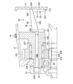
- FIG. 3 is a partial cross-sectional view of the vicinity of an idler shaft 23 to which the oil receiver 3A of Embodiment 1 is attached. It is a partial sectional view near the idler shaft 23 to which the oil receiver 3B of Embodiment 2 is attached. It is a partial cross section figure around the idler axis
- An oil receiver according to the present embodiment and a transmission including the oil receiver are mounted on a vehicle.
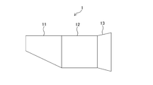
- the transmission includes a case 1 that is divided into a rear case (first case) 11, a middle case (third case) 12, and a front case (second case) 13.
- the transmission includes three rotation center shafts of an input shaft 21, an output shaft 22, and an idler shaft 23.
- a rolling member is attached to each of the rotation center shafts (21 to 23) so as to be capable of synchronous rotation or relative rotation with the rotation center shaft.
- a gear 211 is attached to the input shaft 21 as a rolling member, and other gears, a clutch hub, a synchronizer ring, and the like are also attached.
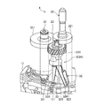
- FIG. 2 shows a state in which one end of each of the input shaft 21 and the output shaft 22 of the sub assembly 4 is inserted into the rear case 11.
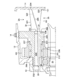
- the oil receiver 3 ⁇ / b> A according to the first embodiment is attached to an idler shaft (first rotation center shaft) 23 as shown in FIGS. 2 and 3.
- the idler shaft 23 to which the oil receiver 3A is attached has one end 232 pivotally supported by the front case 13 as shown in FIG.
- the other end 233 is fixed to the middle case 12 with a bolt 14.
- the bolt 14 is screwed into the other end 233 from the outside of the middle case 12, and the idler shaft 23 is installed so as not to rotate with respect to the middle case 12, that is, the case 1.
- a lubricating oil passage 235 through which lubricating oil flows is defined inside the idler shaft 23.
- the lubricating oil passage 235 is formed along the axial direction, and one side opens to the one end 232 side, and the other opens to the other end 233 side.
- An idler gear 231 is attached to the outer periphery of the idler shaft 23 via a bearing 236 so as to be relatively rotatable.
- the idler gear 231 is engaged with a gear 212 formed integrally with the input shaft 21.
- the diameter of the other end 233 is larger than the diameter of the one end 232, and there is a step 237.
- the idler gear 231 abuts on the step 237 and the axial movement toward the other end 233 is restricted.
- an engaged portion 238 that is recessed toward the one end 232 side in the axial direction is formed on the other end 233 side, and an engaging portion 332 of an oil receiver 3A described later is engaged.
- the oil receiver 3 ⁇ / b> A includes a shaft support portion 31, a receiving portion 32, and a holding portion 33.
- the shaft support portion 31 is one idler shaft 23 side of the receiving portion 32 and the holding portion 33 in the axial direction of the idler shaft 23, and is a portion integrally connecting the receiving portion 32 and the holding portion 33. 23 to support the oil receiver 3A.
- the receiving portion 32 is a box-shaped member that is located between the idler shaft 23 and the rear case 11 in the axial direction of the idler shaft 23 and that opens upward when the transmission is mounted on the vehicle.
- the receiving portion 32 receives the lubricating oil from the upper opening 321 and causes the received lubricating oil to flow along the bottom surface 322 to the idler shaft 23 side.
- the bottom surface 322 is inclined from the rear case 11 side toward the idler shaft 23 side so that the idler shaft 23 side is lowered.
- the receiving part 32 further includes a discharge part 323 and a case contact part 324.
- the discharge portion 323 is located on the idler shaft 23 side, and has a cylindrical shape protruding from the lubricant passage 235 so that the lubricant flowing along the bottom surface 322 is discharged to the lubricant passage 235 of the idler shaft 23. And engages with the lubricating oil passage 235.
- the case contact portion 324 is a side portion that is located on the rear case 11 side and contacts the rear case 11.
- the holding portion 33 is positioned between the idler shaft 23 and the rear case 11 in the axial direction of the idler shaft 23 on the bottom 325 side of the receiving portion 32 (lower side when the transmission is mounted on the vehicle).
- a part 331, an engaging part 332, and an installation part 333 are provided.
- the engaging portion 332 is positioned on the idler shaft 23 side of the main body portion 331 in the axial direction, protrudes from the idler shaft 23, and is inserted into the engaged portion 238 at the other end 233 of the idler shaft 23 to be engaged.
- the installation portion 333 is located on the rear case 11 side of the main body portion 331 in the axial direction, contacts the rear case 11, and engages the protruding portion 111 of the rear case 11.
- the main body 331 is inclined upward so as to become narrower in the vertical direction from the idler shaft 23 toward the rear case 11.
- the oil receiver 3 ⁇ / b> A receives the lubricating oil that scatters, flies, or drops from the opening 321 of the portion 32, flows along the bottom surface 322 to the discharging portion 323, and is led out from the discharging portion 323 to the lubricating oil passage 235.
- the lubricating oil that has flowed into the lubricating oil passage 235 flows out of the lubricating oil passage 235 from the side opposite to the oil receiver 3A that has flowed in, and is guided to the location where the lubricating oil is to be supplied or to the bottom of the case 1 (not shown). It is burned.
- the idler gear 231 and the oil receiver 3A are assembled to the idler shaft 23. Either may be assembled first.
- the idler gear 231 is inserted together with the bearing 236 from the one end 232 side of the idler shaft 23 as shown in FIG. 3 and abuts against the step 237 of the idler shaft 23.
- the idler gear 231 and the bearing 236 are restricted from moving toward the other end 233 in the axial direction by the step 237.
- the oil receiver 3A engages the discharge portion 323 of the receiving portion 32 with the lubricating oil passage 235 of the idler shaft 23, engages the engaging portion 332 of the holding portion 33 with the engaged portion 238 of the idler shaft 23, and The shaft 23 is assembled.
- a state where the idler gear 23 and the oil receiver 3A are assembled to the idler shaft 23 is referred to as an idler shaft sub-assembly.
- each rolling member and other members are assembled so that the idler gear 231 is attached to the idler shaft 23, and the input shaft sub-assembly and the output shaft sub-assembly are assembled.
- the input shaft sub-assembly, output shaft sub-assembly, and idler shaft sub-assembly are in the state of one sub-assembly 4 by engaging and engaging with other sub-assembly members, if necessary, among the members assembled to them. (See FIG. 2).
- the subassembly 4 is assembled to the rear case 11.
- the rear case 11 is held with the side coupled to the middle case 12 facing up.
- the sub assembly 4 inserts one end of the input shaft 21 and the output shaft 22 into the rear case 11 from above the held rear case 11 with one end of the input shaft 21 and the output shaft 22 facing downward.
- the oil receiver 3A is positioned below the idler gear 231. With the input shaft 21 and one end of the output shaft 22 inserted, the receiving portion 32 of the oil receiver 3A is in contact with the rear case 11 and the installation portion 333 of the holding portion 33 is in contact with the rear case 11. Touch.
- a protruding portion 111 protruding toward the middle case 12 is formed at a location where the installation portion 333 of the oil receiver 3A of the rear case 11 contacts.
- the idler shaft sub-assembly is positioned by aligning the installation portion 333 with the protruding portion 111. Since the oil receiver 3A is also in contact with the rear case 11 at the case contact portion 324 of the receiving portion 32, the idler shaft subassembly is held at a predetermined position by the oil receiver 3A.
- the middle case 12 is assembled.
- the middle case 12 is covered from above the rear case 11 and the sub assembly 4 so as to cover the sub assembly 4 and is fixed to the rear case 11 in this state.
- Other members are further fixed to the middle case 12 with bolts or the like.
- One of them is an idler shaft 23.
- the bolt 14 is inserted in a direction substantially orthogonal to the idler shaft 23, and the idler shaft 12 is fixed to the middle case 12 by the bolt 14 (see FIG. 3).
- the front case 13 is assembled.
- the other end of the input shaft 21 and the output shaft 22 is inserted into the front case 13.
- the idler shaft 23 is also inserted into the front case 13 at one end 232 on the same side as the other ends of the input shaft 21 and the output shaft 22 in the axial direction (see FIG. 3).
- the front case 13 and the middle case 12 are fixed, and the assembly of the transmission housed in the case 1 is completed.
- a clutch (not shown) is attached to the other end of the input shaft 21, or a ring gear (not shown) of the differential device is engaged with a final gear located on one end side of the output shaft 22. Since the assembling methods and processes employ known methods and processes and are not directly related to the invention according to the present specification, description thereof will be omitted.
- the oil receiver 3 ⁇ / b> A according to the first embodiment is located between the idler shaft 23 and the rear case 11, the idler shaft 23 side with the shaft support portion 31 is in contact with the idler shaft 23, and the case contact portion 324 of the receiving portion 32. And the installation part 333 of the holding part 33 contacts the rear case 11.
- the receiving portion 32 and the holding portion 33 are integrally connected by a shaft support portion 31.
- the idler shaft 23 and the idler gear 231 are not directly in contact with the rear case 11 and are therefore held against the rear case 11 by the oil receiver 3A.
- the oil receiver 3 ⁇ / b> A is not simply located between and in contact with the idler shaft 23 and the rear case 11.
- the receiving portion 32 has a shape that widens from the idler shaft 23 side toward the rear case 11.
- the holding part 33 is located on the opposite side of the direction in which the receiving part 32 spreads. That is, the oil receiver 3A as a whole is divided into two forks to hold the idler shaft 23. Since the oil receiver 3A does not protrude from the case 1, it does not get in the way of assembly work.
- maintenance part 33 is not directly related to the function as an oil receiver, it contributes to the oil receiver 3A holding
- the oil receiver 3 ⁇ / b> B includes a shaft support portion 31, a receiving portion 32, and a holding portion 34. Since the shaft support portion 31, the receiving portion 32, and the idler shaft 23 have the same configuration as the shaft support portion 31, the receiving portion 32, and the idler shaft 23 of the oil receiver according to the first embodiment, detailed description thereof is omitted.
- the holding part 34 includes a main body part 341, an engaging part 342, and an installation part 343.
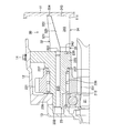
- the main body portion 341 has a trapezoidal shape extending downward from the entirety of the lower portion of the receiving portion 32 (direction when the transmission is mounted on the vehicle), and is located between the idler shaft 23 and the rear case 11.
- An engaging portion 342 that protrudes from the shaft support portion 31 toward the idler shaft 23 is provided, and the installation portion 343 on the rear case side 11 abuts along the rear case 11 from the bottom portion 325 side of the receiving portion 32.
- the holding portion 34 since the holding portion 34 includes the main body portion 341 from the receiving portion 32 to the entire bottom side 325, there is a configuration in which the idler shaft 23 is continuous to the rear case 11. . Therefore, according to the oil receiver 3B of the second embodiment, the idler shaft 23 can be more securely held in the axial direction.
- the oil receiver 3 ⁇ / b> C of the third embodiment includes a shaft support portion 31, a receiving portion 32, and a holding portion 35. Since the shaft support portion 31, the receiving portion 32, and the idler shaft 23 have the same configuration as the shaft support portion 31, the receiving portion 32, and the idler shaft 23 of the oil receiver according to the first embodiment, detailed description thereof is omitted.
- the holding unit 35 includes a main body unit 351 and an installation unit 353.
- the main body portion 351 has a shape along the rear case 11 from below the case contact portion 324 of the receiving portion 32 (direction when the transmission is mounted on the vehicle), and the installation portion 353 is attached to the rear case 11 on the main body. This is the rear case side 11 of the portion 351.
- the oil receiver 3 ⁇ / b> C has a shape in which the opening 321 of the receiving portion 32 is turned upward and the whole is seen from the side, as seen from the side of the high heel. Positioning can be performed by engaging a portion of the main body portion 351 away from the end portion 3511 and the bottom portion 325 of the receiving portion 32 with the protrusion 112 formed on the rear case 11.
- the discharge part 323 of the oil receiver 3 (3A, 3B, 3C) does not have to be engaged with the lubricating oil passage 325 without a gap, and the case contact part 324 and the installation part 333 are in contact with the rear case 11.
- the idler shaft 23 is held even when the assembly operation is performed with the rear case 11 facing downward.
- the idler shaft 23 is fixed to the case 1 if the holding is maintained when the middle case 12 and the front case 13 are installed.
Landscapes
- Engineering & Computer Science (AREA)
- General Engineering & Computer Science (AREA)
- Mechanical Engineering (AREA)
- General Details Of Gearings (AREA)
Abstract
Description
前記ケースに軸支される複数の回転中心軸と、
前記複数の回転中心軸に回転可能に取り付けられる複数の転動部材と、を有する変速機に用いるオイルレシーバーであって、
前記回転中心軸の軸線方向において前記ケースのうちの1つである第1のケースと、前記回転中心軸のうちの1つであり前記第1のケースに当接しない第1の回転中心軸との間に位置し、前記第1の回転中心軸の一方を支持する軸支持部と、
前記軸支持部及び前記第1のケースの間に位置し、前記第1の回転中心軸の一方が前記第1のケースに当接し、前記変速機内の潤滑油を受ける受け部と、
前記第1の回転中心軸の一方が前記第1のケースに当接し、前記受け部が潤滑油を受けるのとは逆側で前記軸支持部及び前記第1のケースの間に位置する保持部と、
を備えることである。
(2)の発明は、前記保持部が前記第1の回転中心軸の他方が前記軸支持部に当接することである。
(3)の発明は、前記第1の回転中心軸が内部に軸線方向に形成された潤滑油路を備え、
前記受け部が受けた潤滑油を排出する排出部を備え、
前記排出部と前記潤滑油路とが連通することである。
本実施形態1のオイルレシーバー3Aは、図2及び図3に示すように、アイドラ軸(第1の回転中心軸)23に取り付けられる。まず、オイルレシーバー3Aが取り付けられているアイドラ軸23は、図3に示すように、一端232がフロントケース13に軸支されている。そして、他端233はミドルケース12にボルト14によって固定されている。他端233には、ボルト14がミドルケース12外部から螺合し、アイドラ軸23はミドルケース12、つまりケース1に対して回転不能に設置される。また、アイドラ軸23の内部には潤滑油が流れる潤滑油路235が区画されている。潤滑油路235は、軸線方向に沿って形成されており、一方が一端232側に開口しており、他方が他端233側に開口している。また、アイドラ軸23の外周にはアイドラギヤ231がベアリング236を介して相対回転可能に取り付けられている。アイドラギヤ231が噛合しているのは、入力軸21と一体成形されているギヤ212である。他端233の直径は一端232の直径よりも大きく、段差237がある。段差237にアイドラギヤ231が当接し、他端233側への軸方向移動が規制されている。また、他端233側には軸線方向で一端232側に窪んだ被係合部238が形成されており、後述するオイルレシーバー3Aの係合部332が係合する。
オイルレシーバー3Aは、軸支持部31と受け部32と保持部33とを備える。軸支持部31は、アイドラ軸23の軸線方向で受け部32及び保持部33の一方のアイドラ軸23側であり、受け部32と保持部33とを一体的に連結する部分であり、アイドラ軸23と当接してオイルレシーバー3Aを支持する。受け部32は、アイドラ軸23の軸線方向でアイドラ軸23とリアケース11との間に位置し、変速機が車両に搭載されている際の上方が開口した箱状の部材である。受け部32は、上方の開口321から潤滑油を受け、受けた潤滑油を底面322に沿ってアイドラ軸23側に流す。底面322は、アイドラ軸23側が低くなるように、リアケース11側からアイドラ軸23側に向かって傾斜している。受け部32は、更に、排出部323とケース当接部324とを備える。排出部323は、アイドラ軸23側に位置し、底面322に沿って流れた潤滑油をアイドラ軸23の潤滑油路235に排出するように潤滑油路235に対して突出した筒状をしており、潤滑油路235に係合する。ケース当接部324は、リアケース11側に位置し、リアケース11に当接する側面部分である。
オイルレシーバー3Aは、飛散、飛翔あるいは滴下する潤滑油を受け部32の開口321から受け、底面322に沿って排出部323に流し、排出部323から潤滑油路235へと導出する。潤滑油路235へと流れた潤滑油は、流れ込んだオイルレシーバー3Aとは逆側から潤滑油路235を流出していき、潤滑油を供給したい箇所やケース1の底部(図示略)へと導かれる。例えば、入力軸21又は出力軸22の転動部材(ギヤなど)の外周側、入力軸21や出力軸21の内部に区画された流路から転動部材の内周側、あるいは下に溜まっている潤滑油に戻す、などが考えられる。
次に、本実施形態1のオイルレシーバー3Aを変速機に組み付ける方法を説明する。まず、アイドラ軸23にアイドラギヤ231とオイルレシーバー3Aとを組み付ける。どちらを先に組み付けても良い。アイドラギヤ231はベアリング236とともに、図3に示すようにアイドラ軸23の一端232側から挿入され、アイドラ軸23の段差237に当接する。アイドラギヤ231及びベアリング236は、段差237によって、軸線方向で他端233側への移動が規制される。オイルレシーバー3Aは、アイドラ軸23の潤滑油路235に受け部32の排出部323を係合し、アイドラ軸23の被係合部238に保持部33の係合部332を係合し、アイドラ軸23に組み付けられる。アイドラ軸23にアイドラギヤ23及びオイルレシーバー3Aが組み付けられた状態をアイドラ軸サブアッシーと称する。
本実施形態1のオイルレシーバー3Aは、アイドラ軸23とリアケース11との間に位置し、軸支持部31のあるアイドラ軸23側がアイドラ軸23と当接し、受け部32のケース当接部324及び保持部33の設置部333がリアケース11に当接する。受け部32と保持部33とは軸支持部31で一体的に連結している。変速機が組み立てられた状態あるいはフロントケース13を下側にしてアイドラ軸23が組み付けられる場合は、アイドラ軸23はフロントケース13に軸支される。そして、フロントケース13を下側にしてアイドラ軸23が組み付けられる場合はアイドラギヤ231がフロントケース13に保持される形状、構成である(図3参照)。リアケース11を下側にして組み付ける際は、アイドラ軸23及びアイドラギヤ231は直接リアケース11に当接しないため、オイルレシーバー3Aによってリアケース11に対して保持される。オイルレシーバー3Aは単にアイドラ軸23とリアケース11との間に位置して当接しているだけではない。受け部32はアイドラ軸23側からリアケース11に向かって広がる形状である。保持部33は受け部32の広がる方向の逆側に位置する。つまり、オイルレシーバー3A全体として二股に分かれてアイドラ軸23を保持している。オイルレシーバー3Aは、ケース1からはみ出したりする形状ではないため、組み付け作業で邪魔にならない。更に、保持部33は、オイルレシーバーとしての機能に直接関係ないが、オイルレシーバー3Aが位置を保持するのに貢献している。オイルレシーバー3Aの排出部323とアイドラ軸23の潤滑油路235との係合が隙間なくしっかりと嵌合していなかったとしても、保持部33によって、当該係合が外れにくい。よって、リアケース11を下にして組み付け作業が行われる場合、オイルレシーバー3Aによってアイドラ軸23及びアイドラギヤ231は位置を保持し、組み付けが困難であったり、組み付けに支障がでたりし難い。
本実施形態2のオイルレシーバー3Bは、図4に示すように、軸支持部31と受け部32と保持部34とを備える。軸支持部31、受け部32及びアイドラ軸23は、実施形態1のオイルレシーバーの軸支持部31及び受け部32、そしてアイドラ軸23と同様の構成であるため、詳細な説明は省略する。
本実施形態3のオイルレシーバー3Cは、図5に示すように、軸支持部31と受け部32と保持部35とを備える。軸支持部31、受け部32及びアイドラ軸23は、実施形態1のオイルレシーバーの軸支持部31及び受け部32、そしてアイドラ軸23と同様の構成であるため、詳細な説明は省略する。
以上、本発明の好適な実施形態について説明したが、本発明は上記実施形態に限定されるものではない。例えば、オイルレシーバー3(3A、3B、3C)の排出部323は、潤滑油路325に隙間なく係合しなくても良く、ケース当接部324及び設置部333がリアケース11に当接することで、リアケース11を下側にして組み付け作業が行われてもアイドラ軸23は保持される。アイドラ軸23は、ミドルケース12やフロントケース13が設置される際に、保持が維持されれば、ケース1に対して固定される。変速機として組み立て後、つまり、受け部32の開口321が上方に位置する状態においても、軸支持部31及びリアケース11に当接する保持部33~35の形状によりオイルレシーバー3は下方に下がりにくい。
Claims (5)
- 複数に分割可能なケースと、
前記ケースに軸支される複数の回転中心軸と、
前記複数の回転中心軸に回転可能に取り付けられる複数の転動部材と、を有する変速機に用いるオイルレシーバーであって、
前記ケースのうちの1つである第1のケースと、前記回転中心軸のうちの1つであり前記第1のケースに当接しない第1の回転中心軸との間に位置し、前記第1の回転中心軸の一方を支持する軸支持部と、
前記軸支持部及び前記第1のケースの間に位置し、前記第1の回転中心軸の一方が前記第1のケースに当接し、前記変速機内の潤滑油を受ける受け部と、
前記第1の回転中心軸の一方が前記第1のケースに当接し、前記受け部が潤滑油を受けるのとは逆側で前記軸支持部及び前記第1のケースの間に位置する保持部と、
を備えるオイルレシーバー。 - 前記保持部は、前記第1の回転中心軸の他方が前記軸支持部に当接する請求項1に記載のオイルレシーバー。
- 前記第1の回転中心軸は内部に軸線方向に形成された潤滑油路を備え、
前記受け部は受けた潤滑油を排出する排出部を備え、
前記排出部と前記潤滑油路とが連通する請求項1又は2に記載のオイルレシーバー。 - 前記第1の回転中心軸は、前記複数に分割可能なケースのうちの1つである第2のケースに、前記第1の回転中心軸の他方を軸支される請求項1~3の何れか1項に記載のオイルレシーバー。
- 請求項1~4の何れか1つに記載のオイルレシーバーを有する変速機。
Priority Applications (1)
| Application Number | Priority Date | Filing Date | Title |
|---|---|---|---|
| DE112014001714.0T DE112014001714T5 (de) | 2013-03-27 | 2014-03-27 | Ölsammler und Zahnradgetriebe |
Applications Claiming Priority (2)
| Application Number | Priority Date | Filing Date | Title |
|---|---|---|---|
| JP2013-066360 | 2013-03-27 | ||
| JP2013066360A JP6035181B2 (ja) | 2013-03-27 | 2013-03-27 | オイルレシーバー及び変速機 |
Publications (1)
| Publication Number | Publication Date |
|---|---|
| WO2014156172A1 true WO2014156172A1 (ja) | 2014-10-02 |
Family
ID=51623184
Family Applications (1)
| Application Number | Title | Priority Date | Filing Date |
|---|---|---|---|
| PCT/JP2014/001798 Ceased WO2014156172A1 (ja) | 2013-03-27 | 2014-03-27 | オイルレシーバー及び変速機 |
Country Status (3)
| Country | Link |
|---|---|
| JP (1) | JP6035181B2 (ja) |
| DE (1) | DE112014001714T5 (ja) |
| WO (1) | WO2014156172A1 (ja) |
Citations (4)
| Publication number | Priority date | Publication date | Assignee | Title |
|---|---|---|---|---|
| JPS58177652U (ja) * | 1982-05-21 | 1983-11-28 | トヨタ自動車株式会社 | 変速機の潤滑機構 |
| JPS59189956U (ja) * | 1983-06-04 | 1984-12-17 | ダイハツ工業株式会社 | 歯車変速機の潤滑装置 |
| JPS63123860U (ja) * | 1987-02-04 | 1988-08-11 | ||
| JP2005054874A (ja) * | 2003-08-04 | 2005-03-03 | Kubota Corp | エンジンの出力歯車列におけるアイドルギヤの軸受装置 |
Family Cites Families (1)
| Publication number | Priority date | Publication date | Assignee | Title |
|---|---|---|---|---|
| EP2256373A1 (de) * | 2009-05-29 | 2010-12-01 | Siemens Aktiengesellschaft | Vorrichtung zur Schmierstoffversorgung eines Lagers in einem Getriebe |
-
2013
- 2013-03-27 JP JP2013066360A patent/JP6035181B2/ja not_active Expired - Fee Related
-
2014
- 2014-03-27 WO PCT/JP2014/001798 patent/WO2014156172A1/ja not_active Ceased
- 2014-03-27 DE DE112014001714.0T patent/DE112014001714T5/de not_active Ceased
Patent Citations (4)
| Publication number | Priority date | Publication date | Assignee | Title |
|---|---|---|---|---|
| JPS58177652U (ja) * | 1982-05-21 | 1983-11-28 | トヨタ自動車株式会社 | 変速機の潤滑機構 |
| JPS59189956U (ja) * | 1983-06-04 | 1984-12-17 | ダイハツ工業株式会社 | 歯車変速機の潤滑装置 |
| JPS63123860U (ja) * | 1987-02-04 | 1988-08-11 | ||
| JP2005054874A (ja) * | 2003-08-04 | 2005-03-03 | Kubota Corp | エンジンの出力歯車列におけるアイドルギヤの軸受装置 |
Also Published As
| Publication number | Publication date |
|---|---|
| JP6035181B2 (ja) | 2016-11-30 |
| DE112014001714T5 (de) | 2015-12-10 |
| JP2014190430A (ja) | 2014-10-06 |
Similar Documents
| Publication | Publication Date | Title |
|---|---|---|
| JP5553817B2 (ja) | 変速機の潤滑油供給構造 | |
| JP2009275732A (ja) | 回転軸の軸受潤滑構造 | |
| US20160053883A1 (en) | Lubricating Device for Transmission | |
| JP5808698B2 (ja) | キャリア支持構造 | |
| JP5722606B2 (ja) | ギヤ装置における軸受の潤滑構造 | |
| JP2016080152A5 (ja) | ||
| JP2016080152A (ja) | 差動装置 | |
| JP2006316932A (ja) | トランスファーの潤滑機構 | |
| JP6035181B2 (ja) | オイルレシーバー及び変速機 | |
| CN110360294A (zh) | 差动装置 | |
| JP5038208B2 (ja) | トランスミッションにおける潤滑構造 | |
| JP2012137113A (ja) | シャフト装置 | |
| JP5051040B2 (ja) | ディファレンシャル装置 | |
| US20200318719A1 (en) | Differential device | |
| US7399253B2 (en) | Washer and planetary gear set having the same | |
| JP4234557B2 (ja) | 遊星歯車装置 | |
| JP2008223866A (ja) | 車両の終減速装置 | |
| JP2013234728A (ja) | 軸受の潤滑構造 | |
| JP2019132333A (ja) | デファレンシャル装置 | |
| JP6578763B2 (ja) | 変速機のドグプレート取付構造 | |
| JP6169018B2 (ja) | 車両用トランスミッション | |
| JP2006242295A (ja) | 差動制限装置 | |
| JP2009162311A (ja) | 軸受部材の分割構造 | |
| KR100856566B1 (ko) | 차량용 시트 이송 기어박스 | |
| JP6287662B2 (ja) | 変速機の潤滑装置 |
Legal Events
| Date | Code | Title | Description |
|---|---|---|---|
| 121 | Ep: the epo has been informed by wipo that ep was designated in this application |
Ref document number: 14775580 Country of ref document: EP Kind code of ref document: A1 |
|
| WWE | Wipo information: entry into national phase |
Ref document number: 1120140017140 Country of ref document: DE Ref document number: 112014001714 Country of ref document: DE |
|
| 32PN | Ep: public notification in the ep bulletin as address of the adressee cannot be established |
Free format text: NOTING OF LOSS OF RIGHTS PURSUANT TO RULE 112(1) EPC (EPO FORM 1205A DATED 18/01/2016) |
|
| 122 | Ep: pct application non-entry in european phase |
Ref document number: 14775580 Country of ref document: EP Kind code of ref document: A1 |