WO2014155932A1 - 測定装置及び測定方法 - Google Patents
測定装置及び測定方法 Download PDFInfo
- Publication number
- WO2014155932A1 WO2014155932A1 PCT/JP2014/000666 JP2014000666W WO2014155932A1 WO 2014155932 A1 WO2014155932 A1 WO 2014155932A1 JP 2014000666 W JP2014000666 W JP 2014000666W WO 2014155932 A1 WO2014155932 A1 WO 2014155932A1
- Authority
- WO
- WIPO (PCT)
- Prior art keywords
- path
- measurement
- particles
- conductance
- unit
- Prior art date
Links
- 238000005259 measurement Methods 0.000 title claims abstract description 145
- 238000000691 measurement method Methods 0.000 title claims description 4
- 239000002245 particle Substances 0.000 claims abstract description 131
- 239000012530 fluid Substances 0.000 claims abstract description 50
- 230000005611 electricity Effects 0.000 claims abstract description 14
- 238000004458 analytical method Methods 0.000 claims description 18
- 238000000034 method Methods 0.000 claims description 15
- 210000000601 blood cell Anatomy 0.000 claims description 12
- 208000031481 Pathologic Constriction Diseases 0.000 abstract 4
- 208000037804 stenosis Diseases 0.000 abstract 4
- 230000036262 stenosis Effects 0.000 abstract 4
- 210000004027 cell Anatomy 0.000 description 23
- 238000005516 engineering process Methods 0.000 description 17
- 230000006870 function Effects 0.000 description 16
- 230000005684 electric field Effects 0.000 description 15
- 239000011347 resin Substances 0.000 description 13
- 229920005989 resin Polymers 0.000 description 13
- 238000012545 processing Methods 0.000 description 12
- 230000009471 action Effects 0.000 description 9
- 238000010586 diagram Methods 0.000 description 9
- 239000000463 material Substances 0.000 description 9
- 238000004364 calculation method Methods 0.000 description 8
- 230000007246 mechanism Effects 0.000 description 8
- 239000003990 capacitor Substances 0.000 description 7
- 239000008151 electrolyte solution Substances 0.000 description 6
- 239000000725 suspension Substances 0.000 description 6
- 210000000170 cell membrane Anatomy 0.000 description 5
- 238000001514 detection method Methods 0.000 description 5
- 230000008859 change Effects 0.000 description 4
- 230000008878 coupling Effects 0.000 description 4
- 238000010168 coupling process Methods 0.000 description 4
- 238000005859 coupling reaction Methods 0.000 description 4
- 238000005868 electrolysis reaction Methods 0.000 description 4
- 230000007274 generation of a signal involved in cell-cell signaling Effects 0.000 description 4
- 210000000265 leukocyte Anatomy 0.000 description 4
- 230000008569 process Effects 0.000 description 4
- 229920000089 Cyclic olefin copolymer Polymers 0.000 description 3
- 238000006243 chemical reaction Methods 0.000 description 3
- 230000007423 decrease Effects 0.000 description 3
- 235000013870 dimethyl polysiloxane Nutrition 0.000 description 3
- 239000004205 dimethyl polysiloxane Substances 0.000 description 3
- 239000003792 electrolyte Substances 0.000 description 3
- 210000003743 erythrocyte Anatomy 0.000 description 3
- 239000012212 insulator Substances 0.000 description 3
- 229910052751 metal Inorganic materials 0.000 description 3
- 239000002184 metal Substances 0.000 description 3
- 239000002504 physiological saline solution Substances 0.000 description 3
- 230000010287 polarization Effects 0.000 description 3
- 229920000435 poly(dimethylsiloxane) Polymers 0.000 description 3
- 229920001721 polyimide Polymers 0.000 description 3
- 238000011144 upstream manufacturing Methods 0.000 description 3
- RYGMFSIKBFXOCR-UHFFFAOYSA-N Copper Chemical compound [Cu] RYGMFSIKBFXOCR-UHFFFAOYSA-N 0.000 description 2
- 239000004713 Cyclic olefin copolymer Substances 0.000 description 2
- PXHVJJICTQNCMI-UHFFFAOYSA-N Nickel Chemical compound [Ni] PXHVJJICTQNCMI-UHFFFAOYSA-N 0.000 description 2
- 239000004695 Polyether sulfone Substances 0.000 description 2
- 239000004642 Polyimide Substances 0.000 description 2
- BQCADISMDOOEFD-UHFFFAOYSA-N Silver Chemical compound [Ag] BQCADISMDOOEFD-UHFFFAOYSA-N 0.000 description 2
- 238000013459 approach Methods 0.000 description 2
- 229910052802 copper Inorganic materials 0.000 description 2
- 239000010949 copper Substances 0.000 description 2
- 230000000694 effects Effects 0.000 description 2
- PCHJSUWPFVWCPO-UHFFFAOYSA-N gold Chemical compound [Au] PCHJSUWPFVWCPO-UHFFFAOYSA-N 0.000 description 2
- 229910052737 gold Inorganic materials 0.000 description 2
- 239000010931 gold Substances 0.000 description 2
- 238000010030 laminating Methods 0.000 description 2
- 239000007769 metal material Substances 0.000 description 2
- BASFCYQUMIYNBI-UHFFFAOYSA-N platinum Chemical compound [Pt] BASFCYQUMIYNBI-UHFFFAOYSA-N 0.000 description 2
- 239000004417 polycarbonate Substances 0.000 description 2
- -1 polydimethylsiloxane Polymers 0.000 description 2
- 229920006393 polyether sulfone Polymers 0.000 description 2
- 229910052709 silver Inorganic materials 0.000 description 2
- 239000004332 silver Substances 0.000 description 2
- 238000012935 Averaging Methods 0.000 description 1
- 229910001200 Ferrotitanium Inorganic materials 0.000 description 1
- 239000004743 Polypropylene Substances 0.000 description 1
- 239000004793 Polystyrene Substances 0.000 description 1
- RTAQQCXQSZGOHL-UHFFFAOYSA-N Titanium Chemical compound [Ti] RTAQQCXQSZGOHL-UHFFFAOYSA-N 0.000 description 1
- HCHKCACWOHOZIP-UHFFFAOYSA-N Zinc Chemical compound [Zn] HCHKCACWOHOZIP-UHFFFAOYSA-N 0.000 description 1
- 230000002159 abnormal effect Effects 0.000 description 1
- NIXOWILDQLNWCW-UHFFFAOYSA-N acrylic acid group Chemical group C(C=C)(=O)O NIXOWILDQLNWCW-UHFFFAOYSA-N 0.000 description 1
- 229910052782 aluminium Inorganic materials 0.000 description 1
- XAGFODPZIPBFFR-UHFFFAOYSA-N aluminium Chemical compound [Al] XAGFODPZIPBFFR-UHFFFAOYSA-N 0.000 description 1
- 230000006399 behavior Effects 0.000 description 1
- 238000004422 calculation algorithm Methods 0.000 description 1
- 238000011109 contamination Methods 0.000 description 1
- 210000000805 cytoplasm Anatomy 0.000 description 1
- 230000003247 decreasing effect Effects 0.000 description 1
- 238000010292 electrical insulation Methods 0.000 description 1
- 238000005530 etching Methods 0.000 description 1
- 238000013213 extrapolation Methods 0.000 description 1
- 230000004907 flux Effects 0.000 description 1
- 230000005484 gravity Effects 0.000 description 1
- 210000003168 insulating cell Anatomy 0.000 description 1
- 239000007788 liquid Substances 0.000 description 1
- 238000004519 manufacturing process Methods 0.000 description 1
- 239000012528 membrane Substances 0.000 description 1
- 229910052759 nickel Inorganic materials 0.000 description 1
- CXQXSVUQTKDNFP-UHFFFAOYSA-N octamethyltrisiloxane Chemical compound C[Si](C)(C)O[Si](C)(C)O[Si](C)(C)C CXQXSVUQTKDNFP-UHFFFAOYSA-N 0.000 description 1
- 238000012856 packing Methods 0.000 description 1
- 238000000206 photolithography Methods 0.000 description 1
- 230000004962 physiological condition Effects 0.000 description 1
- 238000004987 plasma desorption mass spectroscopy Methods 0.000 description 1
- 238000007747 plating Methods 0.000 description 1
- 229910052697 platinum Inorganic materials 0.000 description 1
- 229920000515 polycarbonate Polymers 0.000 description 1
- 229920001155 polypropylene Polymers 0.000 description 1
- 229920002223 polystyrene Polymers 0.000 description 1
- 238000012805 post-processing Methods 0.000 description 1
- 238000002310 reflectometry Methods 0.000 description 1
- 238000011160 research Methods 0.000 description 1
- 230000004044 response Effects 0.000 description 1
- 238000005070 sampling Methods 0.000 description 1
- 238000004088 simulation Methods 0.000 description 1
- 229910001220 stainless steel Inorganic materials 0.000 description 1
- 239000010935 stainless steel Substances 0.000 description 1
- 230000001629 suppression Effects 0.000 description 1
- 230000008685 targeting Effects 0.000 description 1
- 229920006259 thermoplastic polyimide Polymers 0.000 description 1
- 239000010936 titanium Substances 0.000 description 1
- 229910052725 zinc Inorganic materials 0.000 description 1
- 239000011701 zinc Substances 0.000 description 1
Images


Classifications
-
- G01N15/131—
-
- G01N15/1023—
-
- G—PHYSICS
- G01—MEASURING; TESTING
- G01N—INVESTIGATING OR ANALYSING MATERIALS BY DETERMINING THEIR CHEMICAL OR PHYSICAL PROPERTIES
- G01N15/00—Investigating characteristics of particles; Investigating permeability, pore-volume, or surface-area of porous materials
- G01N15/02—Investigating particle size or size distribution
- G01N15/0266—Investigating particle size or size distribution with electrical classification
-
- G—PHYSICS
- G01—MEASURING; TESTING
- G01N—INVESTIGATING OR ANALYSING MATERIALS BY DETERMINING THEIR CHEMICAL OR PHYSICAL PROPERTIES
- G01N15/00—Investigating characteristics of particles; Investigating permeability, pore-volume, or surface-area of porous materials
- G01N15/10—Investigating individual particles
- G01N15/1031—Investigating individual particles by measuring electrical or magnetic effects thereof, e.g. conductivity or capacity
-
- G01N15/132—
-
- G01N15/01—
-
- G01N2015/1028—
Definitions
- the present technology relates to a measuring apparatus and a measuring method for measuring the electric quantity of particles such as blood cells.
- a particle counting device such as a blood cell has a flow path including a narrow tube portion such as an orifice or an aperture, and when the particle passes through the thin tube portion, the impedance of the narrow tube portion depends on the area blocked by the particle itself. Change.
- the counting device detects changes in the impedance of the capillary tube by passing a direct current between the electrodes provided on the inlet side and outlet side of the capillary tube in the flow path, thereby measuring the number of particles. ing.
- the apparatus described in Patent Document 1 uses an AC coupling capacitor. Specifically, this apparatus applies a direct current between the electrodes in the same manner as a general apparatus, and from the variation of the total impedance of the system including the orifice in the flow cell, that is, the system including the electric double layer, AC
- the fluctuation from which the DC component has been removed by the coupling capacitor is detected as a voltage fluctuation (for example, see page 4, left column, line 22 of the specification of Patent Document 1).
- an object of the present technology is to provide a measuring apparatus and a measuring method that can suppress the generation of bubbles in the flow path.
- a measurement apparatus includes a generation unit and a measurement unit, a narrow path through which particles pass by a fluid flow, and a measurement electrode unit provided in the vicinity of the narrow path A predetermined measurement is performed using a flow path device having The generation unit is higher than a characteristic frequency defined by the conductance of the fluid including the particles in the constriction path and the electric double layer capacitance formed by the measurement electrode unit, and according to the size of the particles An AC voltage having a frequency region showing the conductance is generated in the measurement electrode unit.
- the measurement unit measures an amount of electricity including at least the conductance when the particles pass through the constriction path in a state where the AC voltage is applied to the measurement electrode unit.
- the present technology can use an AC voltage that does not cause electrolysis instead of a DC voltage. Therefore, it is not necessary to detect voltage fluctuations. Accordingly, since the generation of bubbles is suppressed, a small channel device can be used.
- the measurement unit includes a measurement circuit including the measurement electrode unit, detects a current flowing through the measurement circuit, and calculates a conductance of the fluid including the particles in the constricted path based on the detected current. Also good.
- the measuring device can easily identify the number and type of particles by performing a predetermined calculation using the conductance measured by the measuring unit.
- the measurement apparatus may further include an analysis unit that monitors the time lapse of the conductance and calculates the size of the particles based on the peak value of the conductance. By detecting the conductance peak value, the analysis unit can calculate the particle size using a predetermined relational expression as follows.
- the analysis unit may calculate the size of the particles using at least a function having the conductance and a peak value of the conductance as parameters.
- the particles are blood cells of a living body, and in this case, the generation unit may generate an alternating voltage having a frequency range of 100 Hz to 1 MHz. Alternatively, the generation unit may generate an alternating voltage having a frequency range of 100 kHz to 500 kHz.
- Another measurement apparatus includes a flow path device having a narrow path through which particles pass by a fluid flow, a measurement electrode unit provided in the vicinity of the narrow path, the generation unit, and the measurement described above. Part.
- the flow channel device may include a first flow channel and a second flow channel connected to the first flow channel via the narrowed channel.
- the narrow path and the second flow path may be arranged so that a flow including a velocity component orthogonal to the velocity component of the fluid in the narrow path is formed in the second flow path. .
- a cross flow can be formed by the narrow path and the second flow path, and the phenomenon of “returning” of the particles can be suppressed, and the measurement accuracy of the electric quantity by the measurement unit can be increased.
- the flow channel device may further include a working electrode unit that applies a dielectrophoretic force to the particles in the flow channel.
- the measurement apparatus may further include a control unit that outputs a working voltage signal to the working electrode unit based on the electric quantity measured by the measuring unit.
- grains can be fractionated based on the measured electric quantity.
- the measurement method measures the amount of electricity of the constricted path using a flow path device having a constricted path through which particles pass by a fluid flow and a measurement electrode portion provided in the vicinity of the constricted path. Is the method.
- An AC voltage having a region is generated in the measurement electrode unit. In a state where the AC voltage is applied to the measurement electrode unit, an electric quantity including at least the conductance when the particles pass through the constriction path is measured.
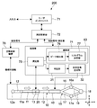
- FIG. 1 is a block diagram illustrating a configuration of a measurement apparatus according to the first embodiment of the present technology.
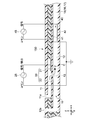
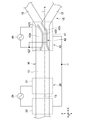
- FIG. 2 is a schematic view of the flow channel device as seen in a cross section along the direction of the flow channel.
- FIG. 3 is a plan view of the second flow path showing the vicinity of the constricted path.
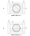
- FIG. 4A schematically shows a state of lines of electric force when a measurement voltage in a low frequency region is applied between the electrodes when cells in the electrolyte are between the measurement electrodes.
- FIG. 4B schematically shows a state of lines of electric force when a measurement voltage in a high frequency region is applied between the electrodes.
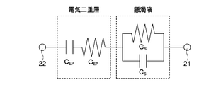
- FIG. 5 shows an electrical equivalent circuit between the measurement electrodes when an electric double layer is generated.
- FIG. 6 is an equivalent circuit that is a simplified representation of the equivalent circuit shown in FIG.
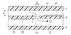
- FIG. 7 is a schematic diagram for illustrating an example of the size of the constriction path structure.
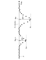
- FIG. 8 shows the relationship between the frequency of the measured voltage and the conductance of the entire system including the electric double layer in the flow path not having the narrow path structure and the flow path having the narrow path structure as in this embodiment. It is a graph.
- FIG. 9 shows a measurement circuit as an example of hardware included in the measuring instrument.
- FIG. 10 is a schematic diagram showing a time-series waveform based on a measurement plot of conductance measured by a measuring instrument.
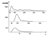
- FIG. 11 shows an example of a histogram of various particles, here blood cells, obtained by the histogram calculation unit.
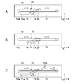
- FIG. 12A to 12C are schematic plan views each showing a flow channel device according to another embodiment.
- FIG. 13 is a block diagram illustrating a configuration of a measurement apparatus according to the second embodiment of the present technology.
- 14 is a cross-sectional view taken along the x direction of the flow channel device of the measurement apparatus shown in FIG.
- FIG. 15 is a plan view showing a second flow path and a branch portion of the flow path device shown in FIG.
- FIG. 1 is a block diagram illustrating a configuration of a measurement apparatus according to the first embodiment of the present technology.
- the measurement apparatus 100 mainly includes a flow channel device 50, a processing unit 73 electrically connected to the flow channel device 50, and a flow control mechanism 78 that controls the fluid of the flow channel device 50.
- the user can input information to the measurement controller 72 using a user interface 71 constituted by a keyboard, a mouse, a touch panel, or the like.
- the measurement controller 72 outputs a control signal corresponding to the input information to the processing unit 73, or obtains a measured value such as an electric quantity (described later) measured by the processing unit 73 and other data.
- the measurement controller 72 can output the information output from the processing unit 73 and the flow control mechanism 78 to, for example, a higher-level device so that the information can be presented to the user.
- the measurement controller 72 and the processing unit 73 are mainly configured by a computer such as a PC or a dedicated machine.
- the measurement controller 72 and the processing unit 73 may be physically separate devices or may be integrated devices.
- the flow channel device 50 is mainly mechanically connected to a flow control mechanism 78 that controls the flow of fluid in the flow channel device 50.
- the flow control mechanism 78 includes a pump, a flow meter, a pressure gauge, and the like.
- the flow channel device 50 is formed in a chip shape, for example, and has a flow channel 10.
- a fluid containing particles as a sample flows through the flow path 10.
- the flow channel 10 is a micro flow channel having a narrow width of about 30 to 200 ⁇ m, for example.
- the particle as a sample is a living body (for example, human or animal) cell, for example, white blood cell or red blood cell.
- the fluid is, for example, physiological saline.
- FIG. 2 is a schematic diagram of the flow channel device 50 as seen in a cross section along the direction of the flow channel 10.
- the flow channel device 50 is configured by laminating a plurality of resin films 3 to 7, for example. Specifically, various electrodes, grooves, holes, and the like are formed on these resin films by photolithography, etching, and the like, and these resin films are aligned and heat-pressed, whereby the flow path device 50 is formed. It is formed.
- Measurement electrodes 21 and 22 of the measurement electrode unit 20 to be described later are formed of, for example, copper, silver, gold, platinum, nickel, zinc, titanium, or stainless steel, or are formed by performing various plating processes thereon. obtain.
- Resin films 3-7 include polyimide film, thermoplastic polyimide film, PDMS (polydimethylsiloxane or dimethylpolysiloxane), acrylic, PES (polyethersulfone), polycarbonate, polypropylene, polystyrene, polyimide, COP (cyclic olefin) Polymer), COC (cyclic olefin copolymer) and the like.
- PDMS polydimethylsiloxane or dimethylpolysiloxane
- acrylic polyES
- PES polyethersulfone
- polycarbonate polypropylene
- polystyrene polystyrene
- polyimide polyimide
- COP cyclic olefin Polymer
- COC cyclic olefin copolymer
- the flow channel device 50 includes a flow channel 10 provided in two stages in the thickness direction of the flow channel device 50.
- the first flow path 11 provided on the upper side has a first inlet 11 a, and particles are passed through the first inlet 11 a by a pipette or a pump included in the flow control mechanism 78.
- a fluid containing C flows into the first flow path 11.
- the second flow path 12 provided on the lower side has a second inlet 12a.
- a fluid not containing particles is introduced into the second flow path 12 via the second inlet 12a by a pump or other equipment (not shown) included in the flow control mechanism 78.
- the pressure of the fluid flowing into the second flow path 12 through the second inlet 12a is preferably constant.
- the second inlet 12 a is the upstream end of the flow path 10.
- a measurement electrode unit 20 for measuring the amount of electricity at a predetermined location of the flow path 10 is provided on the downstream side of the second inlet 12a.
- a drain port 12 b through which particles and fluid flow out from the flow path 10 to the outside is provided at the downstream end of the second flow path 12.
- a particle reservoir for storing particles may be provided in the flow path 10 between the measurement electrode unit 20 and the drainage port 12b.
- the first flow path 11 and the second flow path 12 communicate with each other via a narrow path 13.
- the narrow path 13 has, for example, a flow path size that allows a single particle to pass therethrough, and individual particles C that flow through the first flow path 11 pass through the narrow path 13 through the second flow path. 12 flows in.
- FIG. 3 is a plan view of the second flow path 12 showing the vicinity of the narrow path 13.
- the measurement electrode unit 20 is disposed in the vicinity of the constriction path 13.
- the measurement electrode unit 20 includes measurement electrodes 21 and 22 provided so as to sandwich the narrow path 13.
- the measurement electrodes 21 and 22 are respectively provided on the upper and lower surfaces of the central resin film 5 among the resin films 3 to 7 laminated as shown in FIG. 2, for example, and constitute a parallel plate type capacitor.
- An AC power supply 25 is connected to the measurement electrodes 21 and 22, and a predetermined AC measurement voltage signal on the order of several tens to several hundred mV can be applied.
- the measurement electrode 22 is a common electrode.
- this flow channel device 50 by dividing the flow channel 10 into the first flow channel 11 and the second flow channel 12, in the first flow channel 11 and the narrowed channel 13, the alignment of the particles C is promoted by a constant flow rate.
- the pressure gradient of the fluid in the second channel 12 can be determined predominantly in the second channel 12.
- the stability of the fluid pressure at the outlet portion of the constriction path 13 can be enhanced, so that the flow rate of the fluid passing through the constriction path 13 can be stabilized.
- the width of the second flow path 12 in the y direction is drawn larger than the width of the first flow path 11 in the y direction, but this is for easy understanding of the drawing.
- Both flow paths 11 and 12 are basically the same width.
- the processing unit 73 includes a measuring device 75 and an analysis unit 74.
- the measuring device 75 applies the voltage to the measurement electrode unit 20 by generating an AC measurement voltage signal in a predetermined frequency region described later using the AC power source 25.
- the measuring instrument 75 functions as a generator that generates a measurement voltage signal.
- the measuring instrument 75 measures the amount of electricity when the particles pass through the constriction path 13 in a state where the measurement voltage signal is applied to the measurement electrode unit 20.
- the measuring device 75 functions as a measuring unit that measures the amount of electricity. Examples of the electric quantity include current, voltage, resistivity, impedance, conductivity, conductance, and complex values thereof.
- the analysis unit 74 includes a peak detector 76, a histogram calculation unit 77, and the like. Details of these will be described later.
- a blood cell as a particle is roughly a spherical body of about 10 ⁇ m formed by covering a conductive cytoplasm on an insulating cell membrane having a thickness of about 5 nm.
- a conductive liquid such as plasma or physiological saline
- an electrolyte solution an electrolyte solution
- an alternating voltage is applied to the electrolyte solution, and the dielectric constant of the electrolyte solution and When the conductivity is measured, the following results are obtained.
- the dielectric constant and conductivity are substantially constant in the region where the frequency of the alternating voltage is less than several hundred kHz from the direct current, and in the region of several hundred kHz to several tens of MHz, the change varies significantly according to the frequency. Indicates. However, it is assumed that the contribution of DC conductivity has been removed in advance.
- FIG. 4A schematically shows a state of electric lines of force when a measurement voltage in a low frequency region is applied between the electrodes C1 and C22 in the electrolyte solution between the electrodes such as the measurement electrodes 21 and 22.
- the cell C1 becomes an insulator due to the function of the cell membrane Ca, and the conductivity between the electrodes takes a value reflecting the size of the cell.
- FIG. 4B when a measurement voltage in a high frequency region is applied between the electrodes, the function of the insulator of the cell membrane Ca is lost as described above, and a current flows between the electrodes regardless of the size of the cell C1. It begins to flow.
- the cell membrane Ca functions as an insulator in a relatively low frequency range from DC to several hundred kHz, polarization occurs in the cell membrane Ca, and a constant dielectric constant is detected. Is done.
- the charge in the cell membrane Ca cannot follow the change in electrical polarity, and the function of polarization is relaxed as the frequency increases (dielectric).
- a phenomenon called dielectric relaxation occurs.
- the conductivity shows the same change as this, but contrary to the dielectric constant, the conductivity decreases from a direct current to a low frequency region (substantially constant value) and increases as the frequency increases in a high frequency region.
- the constant conductivity value in the low frequency region of the electrolyte solution containing cells that is, the suspension system, reflects the outer shape of the cell, that is, the size of the cell. Different values are shown for each size.
- This technology uses the AC voltage in the relatively low frequency region as described above while accurately suppressing the generation of bubbles, which was a problem with the prior art, and accurately measures the conductivity (conductance) reflecting the cell size. It is a technology to measure. In addition to this, the present technology can also suppress the cell return phenomenon.
- FIG. 5 shows an electrical equivalent circuit between the measurement electrodes when an electric double layer is generated.
- FIG. 6 is an equivalent circuit that is a simplified representation of the equivalent circuit shown in FIG.
- the electric double layer capacitance is C EP
- its conductance is G EP
- the suspension system capacitance is C s
- its conductance is G s .
- the electric double layer, and the C EP and G EP are connected in series, in the electrolyte, and the C s and G s are connected in parallel.
- the influence of the electric double layer is a single relaxation curve with a characteristic frequency f EP defined by the following equation (1).
- the measured voltage having a frequency higher than the characteristic frequency f EP it can be seen that the influence of the electric double layer is relatively small. Further, by reducing the characteristic frequency fEP itself, the frequency that can be used for measurement can be shifted in a relatively low frequency direction (see FIG. 8 described later). From equation (1), by increasing the C EP, or by decreasing the G s, it is possible to reduce the characteristic frequency f EP. To increase the C EP, increase the surface area of the measuring electrode, or may be increased microscale surface area containing irregularities on effectively contributes measuring electrode in the electric double layer capacitance.
- the flow path device 50 forms the narrowed path 13 and the distance d between the measurement electrodes is set to be small.
- FIG. 7 is a schematic diagram for illustrating an example of the size of the constriction path structure. For example, the following numerical values are adopted, where D is the diameter of the hole of the narrow path 13, h is the height in the z direction of the first flow path 11 and the second flow path 12, and t is the thickness of the resin film. can do.
- the constriction path structure is not limited to the above value, and can be set within a suitable range.
- the hole diameter D can be set to 8 ⁇ m ⁇ D ⁇ 30 ⁇ m. This is because, when the diameter D of the hole is smaller than 8 ⁇ m, the possibility of the blockage of the constricted path 13 is greatly increased by the blood cells passing therethrough. On the other hand, if the diameter of the hole is larger than 30 ⁇ m, it is not possible to ensure the measurement accuracy necessary for distinguishing blood cells and other cells from the viewpoint of size.
- the thickness t of the resin film a value that is as thin as possible to ensure electrical insulation is selected from the viewpoint of measurement accuracy.
- FIG. 8 shows the entire system including the frequency of the measurement voltage and the electric double layer (shown in FIGS. 5 and 6), including the flow path not having the narrow path structure and the flow path having the narrow path structure as in this embodiment. It is a graph which shows the relationship with the conductance of the (equivalent circuit). The graph shows conductance in the case where physiological saline is used as the electrolytic solution and no particles are present in the narrowed path 13.
- the conductance becomes substantially constant regardless of the frequency above a predetermined frequency (characteristic frequency shown in the above formula (1)). It is possible to accurately measure the conductance G s of the suspension system.
- the characteristic frequency can be shifted in the low frequency direction as described above, so that the conductance G of the suspension system is used by using the low frequency region as much as possible. s can be measured. In the example of this graph, it can be seen that the influence of the electric double layer does not reach a frequency of about 100 kHz or more.
- the accurate conductance G s of the suspension system is generated by generating a measurement voltage signal using a frequency that satisfies both the requirements of b) and c). Can be measured.
- Requirement a) depends on the material of the measurement electrodes 21 and 22, the material of the fluid, and the measurement voltage.
- Requirements b) and c) depend on the structure of the flow path device 50, the conductivity of the fluid, the cell type, the cell state, and the fluid material.
- the cells are blood cells, the fluid satisfies physiological conditions, and the values (D, h, t) described above are preferably adopted as the structure and size of the flow channel device 50.
- the characteristic frequency f EP defined by the equation (1) is about 1 kHz. Therefore, it is desirable from the viewpoint of measurement accuracy that the frequency satisfying the requirements b) and c) is in the range of 100 kHz to 500 kHz.
- the frequency range is generally within 100 Hz to 1 MHz.
- a metal material satisfying the requirement a) in this frequency range a general metal material (for example, aluminum, copper, silver, gold, etc.) can be used.
- FIG. 9 shows a measurement circuit as an example of hardware included in the measuring instrument 75.
- the measurement circuit includes the AC power supply 25 and a resistor R s as a current detection passive element.
- a capacitor or an inductor may be used as the passive element.
- Measuring electrode 21 of the measuring electrode portion 20 is connected in series with the resistor R s.
- the voltage of the signal generated by the AC power supply 25 is V out . If the current I is obtained, the impedance (complex impedance) in the measurement electrode unit 20 can be obtained by (V out ⁇ V) / I. If the current path structure is known as described above, the conductance G s can be obtained from the current I.
- the diameter d of the particles can be obtained from the measured conductance by the relational expression (2) shown below using the function g.
- the particles are regarded as substantially spherical (equivalent volume sphere), and the diameter d is an equivalent diameter.
- the function g is obtained as a regression equation using numerical analysis or actual measurement data. It will be described later ⁇ G and G b. Specifically, the following regression equation (3) can be used for the equation (2).
- Parameters such as D, t, c, g, or x, y can be set when the flow channel device 50 is manufactured.
- the flow path device 50 is connected to the main body of the apparatus (that is, the equipment constituting the processing unit 73 or the measurement controller 72) or to the flow control mechanism 78, if those parameters are transmitted to the apparatus main body side.
- a QR (Quick Response) code provided in the flow channel device 50 or a package for packing the flow channel device 50 only needs to include information on those parameters.
- FIG. 10 is a schematic diagram showing a time-lapse waveform of conductance monitored by the measuring instrument 75 and the analysis unit 74 as a measurement plot.
- the conductance measurement plot P is indicated by a black circle.
- the time waveform of the conductance obtained in time series has a peak (G 1 , G 2 ,..., G n ⁇ 1 , G n each time each particle passes. ) Is expressed.
- the peak detector 76 (see FIG.
- the peak detector 76 may detect the peak in real time by hardware, or may detect the peak in post-processing by software.
- a method for detecting a peak there are various known methods such as detection of a peak value from a plurality of sampling values within a predetermined time, detection of a sign of a differential value, or detection by a moving averaging process.
- the ⁇ G at the timing when each particle passes through the constriction path is converted to the cell diameter d by the equations (2) and (3).
- the analysis unit 74 collates the data on the diameter ranges of various particles stored in advance in memory with the diameter d obtained by calculation, and specifies which diameter range the diameter d belongs to. As a result, the type of target particles can be specified. Further, the analysis unit 74 can identify the number of particles of the target type by counting the number of particles belonging to the target diameter range.
- the histogram calculation unit 77 of the analysis unit 74 counts the number of particles for each type of particle, and outputs a fractional histogram. Since the type of particle is specified by calculating the diameter d, this histogram can be formed.
- FIG. 11 shows an example of a histogram of various particles, here blood cells, obtained by the histogram calculator 77.
- WBC White Blood Cell
- RBC Red Blood Blood Cell
- PHT Platelet
- the horizontal axis represents the volume (fl: femtoliter) of various particles calculated from the diameter d.
- the vertical axis represents the normalized number of various particles (relative number). The horizontal axis may not be the volume of the particle but the diameter d itself.
- the measuring apparatus 100 measures an AC voltage having a frequency region in which the influence of the electric double layer is reduced as much as possible and a frequency region that is low enough to obtain a conductance that can reflect the particle size. Used as voltage.
- the measuring apparatus 100 can use an AC voltage that does not cause electrolysis instead of a DC voltage, and there is no need to detect a voltage variation via an AC coupling capacitor as in the prior art. Accordingly, since the generation of bubbles is suppressed, a small channel device 50 can be used. As a result of suppressing the generation of bubbles, the flow of particles can be stabilized, and the measuring device 75 can measure conductance and other electric quantities accurately and stably.
- the measuring apparatus 100 can be used at a hospital bedside, clinic, user's home, or the like. Similarly, the researcher can easily use the measuring apparatus 100 at the research site.
- the measuring apparatus 100 easily identifies the number and type of particles based on the conductance measured by the measuring instrument 75, simply by performing a predetermined calculation using the equations (2) and (3). be able to.
- the flow channel device 50 As shown in FIG. 1, the flow channel device 50 according to the present embodiment is provided so as to be connectable to the processing unit 73 and the flow control mechanism 78, so that the flow channel device 50 can be easily replaced or can be disposable. Used as device 50. Therefore, even when the channel of the channel device 50 is clogged or broken during the measurement, it is possible to take measures such as promptly replacing the channel device 50. In addition, in order to prevent the occurrence of contamination between samples, individual flow channel devices 50 can be used for each sample.
- the fluid pressure at the outlet portion of the narrowed channel 13 is reduced. Since the stability can be improved, the flow rate of the fluid passing through the narrow path 13 can be stabilized. Thereby, the phenomenon of “returning” of the particles can be suppressed, and the measurement accuracy of the electric quantity by the measuring device 75 can be increased.
- the flow channel 10 has a velocity component (horizontal velocity component, here x) orthogonal to the flow direction (z direction) of the fluid containing the particles C in the narrow path 13. Forming a fluid flow (cross flow) in the second flow path 12. Thereby, the flow mode after the second flow path 12 is governed by the cross flow. As a result, the particles C that have exited the constriction path 13 quickly leave the constriction path 13 and flow through the second flow path 12, so that the particles can be prevented from returning to the vicinity of the constriction path 13.
- the fluid having a flow rate larger than that of the fluid in the first flow path 11 and the narrow path 13 is adjusted so as to flow in the second flow path 12.
- a / b which is a flow rate ratio between the first flow rate a and the second flow rate b, is set in a range of 1/2 to 1/50, for example.
- the flow path device 50 is easily manufactured by laminating resin films such as polyimide sheets while having a structure for the measurement.
- the velocity component of the flow in the second flow channel 12 is substantially only the component in the horizontal direction. However, it contains a horizontal component and may also contain a z component. However, in this case, the thickness of the flow path device in the z direction is larger than that of the flow path device 50 shown in FIG.
- FIG. 12A is a schematic plan view showing a flow channel device according to another embodiment.
- a part of the first flow channel 11 is formed non-parallel to the second flow channel 12 when viewed in the z direction.
- the first flow path 11 is arranged with an angle with respect to the second flow path 12 when viewed in the z direction.
- the distance from the inlet 11a of the first flow channel 11 to the narrow path 13 is shorter than that in the flow channel device shown in FIG. 12A. Further, the narrow channel 13 and the subsequent channels of the first channel 11 are parallel to the second channel 12.
- FIG. 12C shows a form in which the first flow path 11 has a drain port 11b.
- the first flow path 11 of the flow path device shown in FIGS. 1 and 12B may also have such a drain port 11b.
- the first flow path 11 and the second flow path 12 may be orthogonal to each other when viewed in the z direction, at least in the vicinity of the narrow path 13.
- FIG. 13 is a block diagram illustrating a configuration of a measurement apparatus according to the second embodiment of the present technology.
- FIG. 14 is a cross-sectional view of the flow channel device 150 of the measuring apparatus 200 along the x direction.
- the same members, functions, and the like included in the measurement apparatus 100 according to the embodiment shown in FIG. 1 and the like will not be described or will be mainly described.
- the flow channel device 150 of the measuring apparatus 200 includes a branch portion 15 that branches from the downstream end of the second flow channel 12, a working electrode portion 40 provided immediately before the branch portion 15, and a downstream side of the branch portion 15.
- a drainage channel 19 and a drainage port 18 are provided.
- the branch part 15 has a plurality of, for example, two branch paths 16 and 17, and particle reservoirs 16 a and 17 a are connected to downstream ends of the branch paths 16 and 17, respectively.
- the drainage channels 19 are connected to the particle reservoirs 16a and 17a, respectively.
- FIG. 15 is a plan view showing the second flow path 12 and the branch portion 15 branched from the second flow path 12.
- the constriction path 13 is disposed so as to be located on a position deviated from the center (position of the branch reference line j) in the y direction which is the width direction of the second flow path 12, for example, on the line k.
- the working electrode unit 40 forms an electric field having a predetermined electric field strength gradient, and applies a dielectrophoretic force to particles flowing through the flow path 10.
- the working electrode part 40 includes a common electrode 41 provided on the upper part of the second flow path 12 and a guide electrode part 42 provided on the lower part thereof.
- An AC power supply 45 is connected to the working electrode section 40, and an AC working voltage is applied between the common electrode 41 and the guide electrode section 42.
- the common electrode 41 functions as a ground electrode and is maintained at a ground potential (common potential).
- the guide electrode section 42 typically includes a plurality of, for example, two elongated line electrodes 42a and 42b.
- the branch paths 16 and 17 are branched at a position on the branch reference line j provided at a substantially central position in the width direction (y direction) of the second flow path 12.
- the guide electrode portion 42 is disposed at a position deviated from the branch reference line j in the y direction.
- the above-described line k is disposed between the line electrodes 42a and 42b.
- the guide electrode part 42 includes an introduction part 421, a rectilinear part 422, and a direction changing part 423.
- the introduction portion 421 is formed so that the line electrodes 42a and 42b approach each other as it goes from the upstream side to the downstream side.
- the rectilinear portion 422 is formed along the second flow path 12, that is, parallel to the x direction.
- the direction conversion unit 423 is formed by changing the direction from the straight traveling unit 422 so as to go to one branch path 16. A voltage is applied to these line electrodes 42a and 42b so as to have the same potential.
- the working electrode section 40 When an AC working voltage is applied to the working electrode section 40, an working electric field is formed between the common electrode 41 and the guide electrode section 42.
- the applied electric field gives the particles a dielectrophoretic force such that the particles travel between the line electrodes 42a and 42b.
- the amplitude of the AC voltage applied to the working electrode unit 40 is 1 V to 30 V, and the frequency is 1 kHz to 100 MHz.
- grain can be changed with the time when a voltage is applied to the working electrode part 40, and when it does not apply, and a particle
- the processing unit 83 includes a determination unit 31 and an action signal generation unit 32 in addition to the measuring device 75 and the analysis unit 74.
- the measuring device 75 calculates a complex impedance as an electric quantity to be measured from the current I described above. Specifically, the measuring device 75 applies multipoint frequencies (3 points or more, typically about 10 to 20 points) with respect to each cell flowing through the constriction path 13 in the above-described frequency region of 100 Hz to 1 MHz. ) To calculate the complex dielectric constant depending on those cells. In addition, the measuring device 75 measures the amount of electricity other than the complex dielectric constant such as conductance and conductivity, and performs the calculation of the histogram in the same manner as in the first embodiment. Is output to the analysis unit 74.
- the measuring instrument 75 calculates a complex dielectric constant from the complex impedance calculated as described above by a known electrical conversion formula, and obtains data including the complex dielectric constant.
- Quantities that are electrically equivalent to the complex permittivity include complex impedance, complex admittance, complex capacitance, and complex conductance. These can be converted into each other by the known simple electric quantity conversion described above.
- the measurement of complex impedance and complex permittivity includes measurement of only the real part or only the imaginary part.
- the determination unit 31 acquires data output from the measuring device 75, and based on the data, whether or not the particle is a particle to be sorted, that is, a predetermined one of the branching units 15 (this embodiment). Then, it is determined whether or not the particle should be led to the branch path 16). Specifically, the determination unit 31 performs the determination process by comparing the measurement data with a determination condition for data related to the complex dielectric constant, which is arbitrarily set in advance to select desired particles in the memory. Do.
- the action signal generation unit 32 generates an action signal when the particles to be measured are particles to be separated (here, particles to be guided to the branch path 16), and otherwise outputs the action signal. Do not generate.
- the action signal generation unit 32 may not generate an action signal when the particles to be measured are particles to be sorted, and may generate an action signal otherwise.
- the determination unit 31 and the action signal generation unit 32 function as a control unit that controls the sorting of particles by generating the action voltage signal.
- the following working electric field is generated by the working electrode section 40 having the guide electrode section 42 (two line electrodes 42a and 42b) and one common electrode 41 facing the guide electrode section 42 (two line electrodes 42a and 42b). That is, an electric field strength gradient in the z direction is generated between the guide electrode portion 42 and the common electrode 41, and an electric field strength gradient in the y direction is generated between the two line electrodes 42a and 42b.
- Dielectrophoretic force is governed by changes in the electric field strength gradient, that is, the density of electric field lines (or electric flux density). This point is different from the electrophoretic force generated in the direction along the electric lines of force. That is, the dielectrophoretic force is not always generated in the direction along the electric lines of force.
- the electric field strength gradient toward the center (position of the line k) between the line electrodes 42a and 42b, that is, the y direction.
- the electric field strength gradient is generated. In this embodiment, it was confirmed that the electric field strength gradient in the y direction is steeper than the electric field strength gradient in the z direction.
- the particles flowing between the line electrodes 42a and 42b are once subjected to the dielectrophoretic force in the z direction, but gradually approach the guide electrode portion 42 (away from the common electrode 41), and between the line electrodes 42a and 42b. It falls within the position on the line k which is the center of.
- the direction changer 423 similarly falls between the line electrodes 42a and 42b due to the steep electric field intensity gradient in the y direction. That is, since the particles move along the line electrodes 42a and 42b, the direction of the movement can be changed.
- the working electrode section 40 instead of the working electrode section 40, the working electrode (voltage applying section) and the voltage applying method described in FIGS. 3 to 12 of JP 2012-98075 A may be employed.
- the measuring apparatus 200 like the measuring apparatus 100 according to the first embodiment, has a function of measuring the quantity of electricity in a desired frequency region and a function of suppressing the return behavior of particles. Have Therefore, since the measurement accuracy by the measuring instrument 75 can be increased, the determination accuracy in the determination unit 31 can also be increased, and consequently the particle sorting accuracy can be increased.
- the analysis unit of the processing unit 83 may include only one type of particles to be counted.
- the analysis unit is not limited to a mode in which the type of particle is specified and counted, and other characteristics of the particle may be analyzed based on the amount of electricity measured by the measuring device 75.
- the measurement circuit shown in FIG. 9 employs the IV method to determine the current flowing through the circuit, but may employ a TDR (Time Domain Domain Reflectometry) method.
- TDR Time Domain Domain Reflectometry
- the present technology can be configured as follows. (1) A conductance of the fluid including the particles in the constricted path of a flow path device having a constricted path through which particles pass by the flow of fluid and a measurement electrode provided near the constricted path, and the measurement A generator for generating an AC voltage in the measurement electrode unit having a frequency region higher than a characteristic frequency defined by the electric double layer capacitance formed by the electrode unit and having a conductance corresponding to the size of the particle; , A measurement device comprising: a measurement unit that measures an amount of electricity including at least the conductance when the particles pass through the constriction path in a state where the AC voltage is applied to the measurement electrode unit.
- the measuring apparatus includes a measurement circuit including the measurement electrode unit, detects a current flowing through the measurement circuit, and calculates a conductance of the fluid including the particles in the constricted path based on the detected current. apparatus.
- the measuring device includes a measurement circuit including the measurement electrode unit, detects a current flowing through the measurement circuit, and calculates a conductance of the fluid including the particles in the constricted path based on the detected current. apparatus.
- a measuring apparatus further comprising an analysis unit that monitors the time lapse of the conductance and calculates the size of the particles based on a peak value of the conductance.
- the analysis unit calculates the size of the particle by using at least the conductance and a function having the conductance peak value as a parameter.
- the measuring device according to any one of (1) to (4), The particles are living blood cells,
- the generating unit generates an AC voltage having a frequency range of 100 Hz to 1 MHz.
- the measuring apparatus according to (5), The generator is a measuring device that generates an AC voltage having a frequency range of 100 kHz to 500 kHz.
- a flow path device having a constriction path through which particles pass by a fluid flow, and a measurement electrode portion provided in the vicinity of the constriction path; It is higher than the characteristic frequency defined by the conductance of the fluid containing the particles in the constricted path of the flow channel device and the electric double layer capacitance formed by the measurement electrode unit, and depends on the size of the particles
- a generator for generating an alternating voltage in the measurement electrode unit having a frequency region showing a high conductance
- a measurement device comprising: a measurement unit that measures an electric quantity including at least the conductance when the particles pass through the constriction path in a state where the AC voltage is generated in the measurement electrode unit.
- the measuring apparatus according to (7), The flow channel device is: A first flow path; And a second flow path connected to the first flow path via the narrow path.
- the measuring apparatus according to (8) or (9), The flow channel device further includes a working electrode portion that applies a dielectrophoretic force to the particles in the flow channel,
- the measuring device is A measuring apparatus further comprising: a control unit that outputs a working voltage signal to the working electrode unit based on the amount of electricity measured by the measuring unit.
- AC voltage having a region is generated in the measurement electrode unit
- a measurement method for measuring an electric quantity including at least the conductance when the particles pass through the constriction path in a state where the AC voltage is generated in the measurement electrode unit.
Abstract
Description
前記発生部は、前記狭窄路における前記粒子を含む前記流体のコンダクタンスと、前記測定電極部により形成される電気二重層キャパシタンスとで規定される特性周波数より高く、かつ、前記粒子の大きさに応じたコンダクタンスを示す周波数領域を持つ交流電圧を前記測定電極部に発生させる。
前記測定部は、前記交流電圧が前記測定電極部に印加された状態で、前記狭窄路を前記粒子が通過する時の少なくとも前記コンダクタンスを含む電気量を測定する。
前記狭窄路における前記粒子を含む前記流体のコンダクタンスと、前記測定電極部により形成される電気二重層キャパシタンスとで規定される特性周波数より高く、かつ、前記粒子の大きさに応じたコンダクタンスを示す周波数領域を持つ交流電圧が前記測定電極部に発生する。
前記交流電圧が前記測定電極部に印加された状態で、前記狭窄路を前記粒子が通過する時の少なくとも前記コンダクタンスを含む電気量が測定される。
図1は、本技術の第1の実施形態に係る測定装置の構成を示すブロック図である。測定装置100は、流路デバイス50と、この流路デバイス50に電気的に接続された処理部73と、流路デバイス50の流体を制御する流動制御機構78とを主に備える。
例えば粒子としての血球細胞は、大まかに言えば、厚さ5nm程度の絶縁性の細胞膜に導電性の細胞質が覆われてできた10μm程度の球状体である。このような構造体が、流体として血漿や生理食塩水などの導電性液体、つまり電解液に浮遊して存在している場合、その電解液に交流電圧を印加してこの電解液の誘電率及び導電率を測定すると、次のような結果となる。それら誘電率及び導電率は、その交流電圧の周波数が直流から数百kHzより小さい領域では実質的に一定であり、数百kHzから数十MHz程度の領域では、その周波数に応じて顕著な変化を示す。ただし、直流導電率の寄与をあらかじめ取り除かれているものとする。
上述したように、導電率の測定結果が細胞のサイズを反映できるようにするために、低周波領域の測定電圧を使用した場合、次のような問題が生じる。電解液中の電極対は、電気二重層キャパシタの機能を発揮し、一般にこの電気二重層キャパシタンスは非常に大きいため、直流~低周波領域の交流電圧による電流は、電気二重層を含む系を流れにくくなる。したがって、直流~低周波領域の測定電圧を用いる場合、懸濁液の系に、この電気二重層による影響を含めてコンダクタンス及びキャパシタンスを考える必要がある。

h=50μm
t=13μm
以上をまとめると、以下のa)の要件を前提として、b)及びc)の両方の要件を満たす周波数を用いて測定電圧信号を発生させることによって、懸濁液の系の正確なコンダクタンスGsを測定することができる。
b)細胞のサイズを反映できるコンダクタンスを取得できる程度に低い周波数領域
c)特性周波数fEPより高い周波数領域
図9は、測定器75が含むハードウェアの一例としての測定回路を示す。測定回路は、上記交流電源25及び電流検出用の受動素子として抵抗Rsを含む。受動素子としては、キャパシタやインダクタが用いられてもよい。測定電極部20の測定電極21が、この抵抗Rsに直列に接続されている。抵抗Rsに加えられる電圧Vを測定することにより、この測定回路に流れる電流(複素電流)Iは、I=V/Rsにより導き出すことができる。交流電源25が発生する信号の電圧をVoutとする。電流Iが求められれば、測定電極部20におけるインピーダンス(複素インピーダンス)は、(Vout-V)/Iによって求めることができる。また、上述のように電流経路の構造が既知であれば、電流IからコンダクタンスGsを求めることができる。

D:狭窄路の孔の直径
t:狭窄路の流路長(上記した樹脂フィルムの厚さ)

従来から、オリフィスの背後に多数の測定済みの粒子が残存しており、それらがオリフィス近傍に舞い戻ることによる疑似信号が測定されてしまう、という問題があった。この問題の解決のために、測定信号からそのような疑似信号を除去するためのアルゴリズムが、例えば特公平7-37934号公報に提示されている。しかしながら、これらの演算は、全体のスループットを低下させたり、異常細胞に由来する小信号を誤って除去してしまったりする等の問題があった。
(1) 流体の流れにより粒子が通過する狭窄路と、前記狭窄路付近に設けられた測定電極部とを有する流路デバイスの、前記狭窄路における前記粒子を含む前記流体のコンダクタンスと、前記測定電極部により形成される電気二重層キャパシタンスとで規定される特性周波数より高く、かつ、前記粒子の大きさに応じたコンダクタンスを示す周波数領域を持つ交流電圧を前記測定電極部に発生させる発生部と、
前記交流電圧が前記測定電極部に印加された状態で、前記狭窄路を前記粒子が通過する時の少なくとも前記コンダクタンスを含む電気量を測定する測定部と
を具備する測定装置。
(2) (1)に記載の測定装置であって、
前記測定部は、前記測定電極部を含む測定回路を有し、前記測定回路に流れる電流を検出し、前記検出した電流に基づき、前記狭窄路における前記粒子を含む前記流体のコンダクタンスを算出する
測定装置。
(3) (1)または(2)に記載の測定装置であって、
前記コンダクタンスの時間経過を監視し、前記コンダクタンスのピーク値に基づき前記粒子の大きさを算出する解析部をさらに具備する
測定装置。
(4) (3)に記載の測定装置であって、
前記解析部は、少なくとも前記コンダクタンス及び前記コンダクタンスのピーク値をパラメータとした関数を用いて、前記粒子の大きさを算出する
測定装置。
(5) (1)から(4)のうちいずれか1つに記載の測定装置であって、
前記粒子は、生体の血球であり、
前記発生部は、100Hz以上1MHz以下の周波数領域を持つ交流電圧を発生する
測定装置。
(6) (5)に記載の測定装置であって、
前記発生部は、100kHz以上500kHz以下の周波数領域を持つ交流電圧を発生する
測定装置。
(7) 流体の流れにより粒子が通過する狭窄路と、前記狭窄路付近に設けられた測定電極部とを有する流路デバイスと、
前記流路デバイスの前記狭窄路における前記粒子を含む前記流体のコンダクタンスと、前記測定電極部により形成される電気二重層キャパシタンスとで規定される特性周波数より高く、かつ、前記粒子の大きさに応じたコンダクタンスを示す周波数領域を持つ交流電圧を前記測定電極部に発生させる発生部と、
前記交流電圧が前記測定電極部に発生した状態で、前記狭窄路を前記粒子が通過する時の少なくとも前記コンダクタンスを含む電気量を測定する測定部と
を具備する測定装置。
(8) (7)に記載の測定装置であって、
前記流路デバイスは、
第1の流路と、
前記第1の流路に前記狭窄路を介して接続された第2の流路とを有する
測定装置。
(9) (8)に記載の測定装置であって、
前記狭窄路内での前記流体の速度成分に直交する速度成分を含む流れが第2の流路に形成されるように、前記狭窄路及び前記第2の流路が配置されている
測定装置。
(10) (8)または(9)に記載の測定装置であって、
前記流路デバイスは、前記流路内で前記粒子に誘電泳動力を作用させる作用電極部をさらに有し、
前記測定装置は、
前記測定部で測定された前記電気量に基づき、作用電圧信号を前記作用電極部に出力する制御部をさらに具備する
測定装置。
(11) 流体の流れにより粒子が通過する狭窄路と、前記狭窄路付近に設けられた測定電極部とを有する流路デバイスを用いて、前記狭窄路の電気量を測定する方法であって、
前記狭窄路における前記粒子を含む前記流体のコンダクタンスと、前記測定電極部により形成される電気二重層キャパシタンスとで規定される特性周波数より高く、かつ、前記粒子の大きさに応じたコンダクタンスを示す周波数領域を持つ交流電圧を前記測定電極部に発生させ、
前記交流電圧が前記測定電極部に発生した状態で、前記狭窄路を前記粒子が通過する時の少なくとも前記コンダクタンスを含む電気量を測定する
測定方法。
10…流路
11…第1の流路
12…第2の流路
13…狭窄路
20…測定電極部
21、22…測定電極
50、150…流路デバイス
74…解析部
75…測定器
76…ピーク検出器
77…ヒストグラム演算部
100、200…測定装置
Claims (11)
- 流体の流れにより粒子が通過する狭窄路と、前記狭窄路付近に設けられた測定電極部とを有する流路デバイスの、前記狭窄路における前記粒子を含む前記流体のコンダクタンスと、前記測定電極部により形成される電気二重層キャパシタンスとで規定される特性周波数より高く、かつ、前記粒子の大きさに応じたコンダクタンスを示す周波数領域を持つ交流電圧を前記測定電極部に発生させる発生部と、
前記交流電圧が前記測定電極部に印加された状態で、前記狭窄路を前記粒子が通過する時の少なくとも前記コンダクタンスを含む電気量を測定する測定部と
を具備する測定装置。 - 請求項1に記載の測定装置であって、
前記測定部は、前記測定電極部を含む測定回路を有し、前記測定回路に流れる電流を検出し、前記検出した電流に基づき、前記狭窄路における前記粒子を含む前記流体のコンダクタンスを算出する
測定装置。 - 請求項1に記載の測定装置であって、
前記コンダクタンスの時間経過を監視し、前記コンダクタンスのピーク値に基づき前記粒子の大きさを算出する解析部をさらに具備する
測定装置。 - 請求項3に記載の測定装置であって、
前記解析部は、少なくとも前記コンダクタンス及び前記コンダクタンスのピーク値をパラメータとした関数を用いて、前記粒子の大きさを算出する
測定装置。 - 請求項1に記載の測定装置であって、
前記粒子は、生体の血球であり、
前記発生部は、100Hz以上1MHz以下の周波数領域を持つ交流電圧を発生する
測定装置。 - 請求項5に記載の測定装置であって、
前記発生部は、100kHz以上500kHz以下の周波数領域を持つ交流電圧を発生する
測定装置。 - 流体の流れにより粒子が通過する狭窄路と、前記狭窄路付近に設けられた測定電極部とを有する流路デバイスと、
前記流路デバイスの前記狭窄路における前記粒子を含む前記流体のコンダクタンスと、前記測定電極部により形成される電気二重層キャパシタンスとで規定される特性周波数より高く、かつ、前記粒子の大きさに応じたコンダクタンスを示す周波数領域を持つ交流電圧を前記測定電極部に発生させる発生部と、
前記交流電圧が前記測定電極部に発生した状態で、前記狭窄路を前記粒子が通過する時の少なくとも前記コンダクタンスを含む電気量を測定する測定部と
を具備する測定装置。 - 請求項7に記載の測定装置であって、
前記流路デバイスは、
第1の流路と、
前記第1の流路に前記狭窄路を介して接続された第2の流路とを有する
測定装置。 - 請求項8に記載の測定装置であって、
前記狭窄路内での前記流体の速度成分に直交する速度成分を含む流れが第2の流路に形成されるように、前記狭窄路及び前記第2の流路が配置されている
測定装置。 - 請求項8に記載の測定装置であって、
前記流路デバイスは、前記流路内で前記粒子に誘電泳動力を作用させる作用電極部をさらに有し、
前記測定装置は、
前記測定部で測定された前記電気量に基づき、作用電圧信号を前記作用電極部に出力する制御部をさらに具備する
測定装置。 - 流体の流れにより粒子が通過する狭窄路と、前記狭窄路付近に設けられた測定電極部とを有する流路デバイスを用いて、前記狭窄路の電気量を測定する方法であって、
前記狭窄路における前記粒子を含む前記流体のコンダクタンスと、前記測定電極部により形成される電気二重層キャパシタンスとで規定される特性周波数より高く、かつ、前記粒子の大きさに応じたコンダクタンスを示す周波数領域を持つ交流電圧を前記測定電極部に発生させ、
前記交流電圧が前記測定電極部に発生した状態で、前記狭窄路を前記粒子が通過する時の少なくとも前記コンダクタンスを含む電気量を測定する
測定方法。
Priority Applications (3)
| Application Number | Priority Date | Filing Date | Title |
|---|---|---|---|
| JP2015507985A JP6299749B2 (ja) | 2013-03-26 | 2014-02-07 | 測定装置 |
| EP14776330.4A EP2980558B1 (en) | 2013-03-26 | 2014-02-07 | Measurement device and measurement method |
| US14/775,099 US20160025610A1 (en) | 2013-03-26 | 2014-02-07 | Measurement apparatus and measurement method |
Applications Claiming Priority (2)
| Application Number | Priority Date | Filing Date | Title |
|---|---|---|---|
| JP2013-063515 | 2013-03-26 | ||
| JP2013063515 | 2013-03-26 |
Publications (1)
| Publication Number | Publication Date |
|---|---|
| WO2014155932A1 true WO2014155932A1 (ja) | 2014-10-02 |
Family
ID=51622958
Family Applications (1)
| Application Number | Title | Priority Date | Filing Date |
|---|---|---|---|
| PCT/JP2014/000666 WO2014155932A1 (ja) | 2013-03-26 | 2014-02-07 | 測定装置及び測定方法 |
Country Status (4)
| Country | Link |
|---|---|
| US (1) | US20160025610A1 (ja) |
| EP (1) | EP2980558B1 (ja) |
| JP (1) | JP6299749B2 (ja) |
| WO (1) | WO2014155932A1 (ja) |
Cited By (4)
| Publication number | Priority date | Publication date | Assignee | Title |
|---|---|---|---|---|
| JP2017129545A (ja) * | 2016-01-22 | 2017-07-27 | 日本光電工業株式会社 | フローセル、粒子分析装置および粒子分析方法 |
| WO2017141685A1 (ja) * | 2016-02-16 | 2017-08-24 | 株式会社Afiテクノロジー | 分離装置 |
| JP2019082485A (ja) * | 2019-01-09 | 2019-05-30 | 株式会社東芝 | 分析チップ |
| JP2019117050A (ja) * | 2017-12-26 | 2019-07-18 | 東ソー株式会社 | 粒子検出装置 |
Families Citing this family (12)
| Publication number | Priority date | Publication date | Assignee | Title |
|---|---|---|---|---|
| CN104937400B (zh) | 2013-01-28 | 2018-07-03 | 索尼公司 | 用于生物样品的阻抗测量装置和用于生物样品的阻抗测量系统 |
| CN105008906B (zh) | 2013-03-13 | 2020-01-07 | 索尼公司 | 血液状态分析装置、血液状态分析系统 |
| CN105008907B (zh) | 2013-03-15 | 2018-12-28 | 索尼公司 | 血液状态分析装置、血液状态分析系统、血液状态分析方法 |
| JPWO2014156370A1 (ja) | 2013-03-29 | 2017-02-16 | ソニー株式会社 | 血液状態評価装置、血液状態評価システム、血液状態評価方法及びプログラム |
| JP6512093B2 (ja) | 2013-03-29 | 2019-05-15 | ソニー株式会社 | 血液状態解析装置、血液状態解析システム、血液状態解析方法及びプログラム |
| US10207266B2 (en) * | 2015-09-29 | 2019-02-19 | Foxconn Interconnect Technology Limited | Microfluidic device for detecting cells of blood |
| US10900884B2 (en) | 2018-03-08 | 2021-01-26 | International Business Machines Corporation | 2D nanoparticle motion sensing methods and structures |
| US10444045B2 (en) | 2018-03-08 | 2019-10-15 | International Business Machines Corporation | 2D nanoparticle motion sensing methods and structures |
| US10422672B1 (en) | 2018-03-08 | 2019-09-24 | International Business Machines Corporation | 2D nanoparticle motion sensing methods and structures |
| WO2019236682A1 (en) | 2018-06-05 | 2019-12-12 | Chronus Health, Inc. | Devices, cartridge, and sensors for controlling liquid movement and analyzing biological samples |
| JP7058579B2 (ja) * | 2018-09-19 | 2022-04-22 | 株式会社アドバンテスト | ポアデバイスおよび微粒子測定システム |
| KR102383813B1 (ko) * | 2019-12-13 | 2022-04-08 | (주)셀라바이오텍 | 나노 잉크를 이용한 전위 측정 기반 수직 방향 입자 정량 측정 장치 및 그 방법 |
Citations (4)
| Publication number | Priority date | Publication date | Assignee | Title |
|---|---|---|---|---|
| JPH0737934A (ja) | 1993-06-29 | 1995-02-07 | Matsushita Electric Ind Co Ltd | フリップチップの実装方法 |
| JP2815435B2 (ja) | 1989-12-22 | 1998-10-27 | 株式会社日立製作所 | 粒子解析装置及び血球カウンタ |
| JP2010181399A (ja) | 2009-01-09 | 2010-08-19 | Sony Corp | 流路デバイス、複素誘電率測定装置及び誘電サイトメトリー装置 |
| JP2012098075A (ja) | 2010-10-29 | 2012-05-24 | Sony Corp | 細胞分取装置、細胞分取チップ及び細胞分取方法 |
Family Cites Families (7)
| Publication number | Priority date | Publication date | Assignee | Title |
|---|---|---|---|---|
| US6058934A (en) * | 1995-11-02 | 2000-05-09 | Chiron Diagnostics Corporation | Planar hematocrit sensor incorporating a seven-electrode conductivity measurement cell |
| DE10311716A1 (de) * | 2003-03-17 | 2004-10-14 | Evotec Oai Ag | Verfahren und Vorrichtung zur Trennung von Partikeln in einer Flüssigkeitsströmung |
| US7390387B2 (en) * | 2004-03-25 | 2008-06-24 | Hewlett-Packard Development Company, L.P. | Method of sorting cells in series |
| EP2259044A1 (en) * | 2009-06-05 | 2010-12-08 | Koninklijke Philips Electronics N.V. | Multi-frequency impedance method and apparatus for discriminating and counting particles expressing a specific marker |
| FR2950972A1 (fr) * | 2009-10-02 | 2011-04-08 | Commissariat Energie Atomique | Procede et cellule de mesure de la concentration globale en ions d'un fluide corporel |
| JP5905212B2 (ja) * | 2010-06-09 | 2016-04-20 | エイペックス バイオテクノロジー コーポレイションApex Biotechnology Corp. | 検体におけるリアクタンスの変化の分析によりプロトロンビン時間を、又はプロトロンビン時間及びヘマトクリットの両方を測定する装置及びその方法 |
| JP5549484B2 (ja) * | 2010-09-01 | 2014-07-16 | ソニー株式会社 | 液体試料の電気特性測定のためのサンプルカートリッジと装置 |
-
2014
- 2014-02-07 EP EP14776330.4A patent/EP2980558B1/en active Active
- 2014-02-07 US US14/775,099 patent/US20160025610A1/en not_active Abandoned
- 2014-02-07 WO PCT/JP2014/000666 patent/WO2014155932A1/ja active Application Filing
- 2014-02-07 JP JP2015507985A patent/JP6299749B2/ja not_active Expired - Fee Related
Patent Citations (4)
| Publication number | Priority date | Publication date | Assignee | Title |
|---|---|---|---|---|
| JP2815435B2 (ja) | 1989-12-22 | 1998-10-27 | 株式会社日立製作所 | 粒子解析装置及び血球カウンタ |
| JPH0737934A (ja) | 1993-06-29 | 1995-02-07 | Matsushita Electric Ind Co Ltd | フリップチップの実装方法 |
| JP2010181399A (ja) | 2009-01-09 | 2010-08-19 | Sony Corp | 流路デバイス、複素誘電率測定装置及び誘電サイトメトリー装置 |
| JP2012098075A (ja) | 2010-10-29 | 2012-05-24 | Sony Corp | 細胞分取装置、細胞分取チップ及び細胞分取方法 |
Cited By (6)
| Publication number | Priority date | Publication date | Assignee | Title |
|---|---|---|---|---|
| JP2017129545A (ja) * | 2016-01-22 | 2017-07-27 | 日本光電工業株式会社 | フローセル、粒子分析装置および粒子分析方法 |
| WO2017141685A1 (ja) * | 2016-02-16 | 2017-08-24 | 株式会社Afiテクノロジー | 分離装置 |
| JP2017143763A (ja) * | 2016-02-16 | 2017-08-24 | 株式会社Afiテクノロジー | 分離装置 |
| JP2019117050A (ja) * | 2017-12-26 | 2019-07-18 | 東ソー株式会社 | 粒子検出装置 |
| JP7205056B2 (ja) | 2017-12-26 | 2023-01-17 | 東ソー株式会社 | 粒子検出装置 |
| JP2019082485A (ja) * | 2019-01-09 | 2019-05-30 | 株式会社東芝 | 分析チップ |
Also Published As
| Publication number | Publication date |
|---|---|
| JPWO2014155932A1 (ja) | 2017-02-16 |
| EP2980558B1 (en) | 2019-11-06 |
| US20160025610A1 (en) | 2016-01-28 |
| EP2980558A1 (en) | 2016-02-03 |
| EP2980558A4 (en) | 2016-10-26 |
| JP6299749B2 (ja) | 2018-03-28 |
Similar Documents
| Publication | Publication Date | Title |
|---|---|---|
| JP6299749B2 (ja) | 測定装置 | |
| JP6299609B2 (ja) | 微小粒子分析装置及び微小粒子分析システム | |
| US10222314B2 (en) | Flow channel device, complex permittivity measuring apparatus, and dielectric cytometry system | |
| Spencer et al. | Positional dependence of particles in microfludic impedance cytometry | |
| Reale et al. | High-throughput electrical position detection of single flowing particles/cells with non-spherical shape | |
| US9505010B2 (en) | Flow channel device and sorting apparatus | |
| Hassan et al. | Flow metering characterization within an electrical cell counting microfluidic device | |
| Caselli et al. | Modeling, simulation, and performance evaluation of a novel microfluidic impedance cytometer for morphology-based cell discrimination | |
| Zhai et al. | Complex admittance detection of horizontal oil-water two-phase flows using a capacitance sensor | |
| Mei et al. | Counting leukocytes from whole blood using a lab-on-a-chip Coulter counter | |
| Claudel et al. | An electrical model optimization for single cell flow impedance spectroscopy | |
| Claudel et al. | High reliability microfluidic biosensor for single cell impedance cytometry | |
| JP3909050B2 (ja) | 血球計数装置 | |
| JP7003640B2 (ja) | 粒子検出装置及び粒子検出方法 | |
| Chen et al. | An Impedance Flow Cytometer Chip with Tunable Impedance Responses for High Sensitive Cellular Biomarker Detection | |
| Das et al. | A bioimpedance-based microflow cytometer with compact electronic instrumentation for counting of microparticles | |
| WO2024052697A1 (en) | Microfluidic device and method for determining a characteristic of a particle | |
| WO2014122491A1 (en) | Testing unit for determining the physical characteristics of samples containing liquid components | |
| Lata et al. | Development of Electrode Polarization Impedance based Bubble Detection in Flow Channels | |
| Hosseini et al. | Low-cost sheath-less microfluidic impedance cytometry for point-of-care applications | |
| Mansor et al. | An impedance flow cytometry with integrated dual microneedle for electrical properties characterization of single cell | |
| Sherif et al. | An improved planar electrode for dielectric parameters extraction | |
| De Bisschop et al. | Electronic gate detection for cell or particle counting and sizing in liquids: Front-end characteristics, flow-dependent gate impedance, and its remediation | |
| Lee et al. | Particle concentration sensor using control volume between double electrical sensing zones | |
| Zhang et al. | Numerical Investigation of the Coulter Principle in a Microfluidic Device |
Legal Events
| Date | Code | Title | Description |
|---|---|---|---|
| 121 | Ep: the epo has been informed by wipo that ep was designated in this application |
Ref document number: 14776330 Country of ref document: EP Kind code of ref document: A1 |
|
| ENP | Entry into the national phase |
Ref document number: 2015507985 Country of ref document: JP Kind code of ref document: A |
|
| WWE | Wipo information: entry into national phase |
Ref document number: 2014776330 Country of ref document: EP |
|
| WWE | Wipo information: entry into national phase |
Ref document number: 14775099 Country of ref document: US |
|
| NENP | Non-entry into the national phase |
Ref country code: DE |