WO2014155471A1 - 符号化方法および符号化装置 - Google Patents
符号化方法および符号化装置 Download PDFInfo
- Publication number
- WO2014155471A1 WO2014155471A1 PCT/JP2013/058487 JP2013058487W WO2014155471A1 WO 2014155471 A1 WO2014155471 A1 WO 2014155471A1 JP 2013058487 W JP2013058487 W JP 2013058487W WO 2014155471 A1 WO2014155471 A1 WO 2014155471A1
- Authority
- WO
- WIPO (PCT)
- Prior art keywords
- encoding
- image
- unit
- region
- analysis
- Prior art date
- Legal status (The legal status is an assumption and is not a legal conclusion. Google has not performed a legal analysis and makes no representation as to the accuracy of the status listed.)
- Ceased
Links
Images



Classifications
-
- H—ELECTRICITY
- H04—ELECTRIC COMMUNICATION TECHNIQUE
- H04N—PICTORIAL COMMUNICATION, e.g. TELEVISION
- H04N19/00—Methods or arrangements for coding, decoding, compressing or decompressing digital video signals
- H04N19/10—Methods or arrangements for coding, decoding, compressing or decompressing digital video signals using adaptive coding
- H04N19/102—Methods or arrangements for coding, decoding, compressing or decompressing digital video signals using adaptive coding characterised by the element, parameter or selection affected or controlled by the adaptive coding
- H04N19/124—Quantisation
-
- B—PERFORMING OPERATIONS; TRANSPORTING
- B60—VEHICLES IN GENERAL
- B60W—CONJOINT CONTROL OF VEHICLE SUB-UNITS OF DIFFERENT TYPE OR DIFFERENT FUNCTION; CONTROL SYSTEMS SPECIALLY ADAPTED FOR HYBRID VEHICLES; ROAD VEHICLE DRIVE CONTROL SYSTEMS FOR PURPOSES NOT RELATED TO THE CONTROL OF A PARTICULAR SUB-UNIT
- B60W50/00—Details of control systems for road vehicle drive control not related to the control of a particular sub-unit, e.g. process diagnostic or vehicle driver interfaces
- B60W50/08—Interaction between the driver and the control system
- B60W50/14—Means for informing the driver, warning the driver or prompting a driver intervention
-
- G—PHYSICS
- G06—COMPUTING OR CALCULATING; COUNTING
- G06V—IMAGE OR VIDEO RECOGNITION OR UNDERSTANDING
- G06V20/00—Scenes; Scene-specific elements
- G06V20/50—Context or environment of the image
- G06V20/56—Context or environment of the image exterior to a vehicle by using sensors mounted on the vehicle
-
- G—PHYSICS
- G08—SIGNALLING
- G08G—TRAFFIC CONTROL SYSTEMS
- G08G1/00—Traffic control systems for road vehicles
- G08G1/16—Anti-collision systems
- G08G1/167—Driving aids for lane monitoring, lane changing, e.g. blind spot detection
-
- H—ELECTRICITY
- H04—ELECTRIC COMMUNICATION TECHNIQUE
- H04N—PICTORIAL COMMUNICATION, e.g. TELEVISION
- H04N19/00—Methods or arrangements for coding, decoding, compressing or decompressing digital video signals
- H04N19/10—Methods or arrangements for coding, decoding, compressing or decompressing digital video signals using adaptive coding
- H04N19/134—Methods or arrangements for coding, decoding, compressing or decompressing digital video signals using adaptive coding characterised by the element, parameter or criterion affecting or controlling the adaptive coding
-
- H—ELECTRICITY
- H04—ELECTRIC COMMUNICATION TECHNIQUE
- H04N—PICTORIAL COMMUNICATION, e.g. TELEVISION
- H04N19/00—Methods or arrangements for coding, decoding, compressing or decompressing digital video signals
- H04N19/10—Methods or arrangements for coding, decoding, compressing or decompressing digital video signals using adaptive coding
- H04N19/134—Methods or arrangements for coding, decoding, compressing or decompressing digital video signals using adaptive coding characterised by the element, parameter or criterion affecting or controlling the adaptive coding
- H04N19/136—Incoming video signal characteristics or properties
- H04N19/137—Motion inside a coding unit, e.g. average field, frame or block difference
- H04N19/139—Analysis of motion vectors, e.g. their magnitude, direction, variance or reliability
-
- H—ELECTRICITY
- H04—ELECTRIC COMMUNICATION TECHNIQUE
- H04N—PICTORIAL COMMUNICATION, e.g. TELEVISION
- H04N19/00—Methods or arrangements for coding, decoding, compressing or decompressing digital video signals
- H04N19/10—Methods or arrangements for coding, decoding, compressing or decompressing digital video signals using adaptive coding
- H04N19/134—Methods or arrangements for coding, decoding, compressing or decompressing digital video signals using adaptive coding characterised by the element, parameter or criterion affecting or controlling the adaptive coding
- H04N19/136—Incoming video signal characteristics or properties
- H04N19/14—Coding unit complexity, e.g. amount of activity or edge presence estimation
-
- H—ELECTRICITY
- H04—ELECTRIC COMMUNICATION TECHNIQUE
- H04N—PICTORIAL COMMUNICATION, e.g. TELEVISION
- H04N19/00—Methods or arrangements for coding, decoding, compressing or decompressing digital video signals
- H04N19/10—Methods or arrangements for coding, decoding, compressing or decompressing digital video signals using adaptive coding
- H04N19/169—Methods or arrangements for coding, decoding, compressing or decompressing digital video signals using adaptive coding characterised by the coding unit, i.e. the structural portion or semantic portion of the video signal being the object or the subject of the adaptive coding
- H04N19/17—Methods or arrangements for coding, decoding, compressing or decompressing digital video signals using adaptive coding characterised by the coding unit, i.e. the structural portion or semantic portion of the video signal being the object or the subject of the adaptive coding the unit being an image region, e.g. an object
-
- H—ELECTRICITY
- H04—ELECTRIC COMMUNICATION TECHNIQUE
- H04N—PICTORIAL COMMUNICATION, e.g. TELEVISION
- H04N19/00—Methods or arrangements for coding, decoding, compressing or decompressing digital video signals
- H04N19/10—Methods or arrangements for coding, decoding, compressing or decompressing digital video signals using adaptive coding
- H04N19/169—Methods or arrangements for coding, decoding, compressing or decompressing digital video signals using adaptive coding characterised by the coding unit, i.e. the structural portion or semantic portion of the video signal being the object or the subject of the adaptive coding
- H04N19/17—Methods or arrangements for coding, decoding, compressing or decompressing digital video signals using adaptive coding characterised by the coding unit, i.e. the structural portion or semantic portion of the video signal being the object or the subject of the adaptive coding the unit being an image region, e.g. an object
- H04N19/174—Methods or arrangements for coding, decoding, compressing or decompressing digital video signals using adaptive coding characterised by the coding unit, i.e. the structural portion or semantic portion of the video signal being the object or the subject of the adaptive coding the unit being an image region, e.g. an object the region being a slice, e.g. a line of blocks or a group of blocks
-
- H—ELECTRICITY
- H04—ELECTRIC COMMUNICATION TECHNIQUE
- H04N—PICTORIAL COMMUNICATION, e.g. TELEVISION
- H04N19/00—Methods or arrangements for coding, decoding, compressing or decompressing digital video signals
- H04N19/10—Methods or arrangements for coding, decoding, compressing or decompressing digital video signals using adaptive coding
- H04N19/169—Methods or arrangements for coding, decoding, compressing or decompressing digital video signals using adaptive coding characterised by the coding unit, i.e. the structural portion or semantic portion of the video signal being the object or the subject of the adaptive coding
- H04N19/17—Methods or arrangements for coding, decoding, compressing or decompressing digital video signals using adaptive coding characterised by the coding unit, i.e. the structural portion or semantic portion of the video signal being the object or the subject of the adaptive coding the unit being an image region, e.g. an object
- H04N19/176—Methods or arrangements for coding, decoding, compressing or decompressing digital video signals using adaptive coding characterised by the coding unit, i.e. the structural portion or semantic portion of the video signal being the object or the subject of the adaptive coding the unit being an image region, e.g. an object the region being a block, e.g. a macroblock
-
- H—ELECTRICITY
- H04—ELECTRIC COMMUNICATION TECHNIQUE
- H04N—PICTORIAL COMMUNICATION, e.g. TELEVISION
- H04N19/00—Methods or arrangements for coding, decoding, compressing or decompressing digital video signals
- H04N19/42—Methods or arrangements for coding, decoding, compressing or decompressing digital video signals characterised by implementation details or hardware specially adapted for video compression or decompression, e.g. dedicated software implementation
- H04N19/436—Methods or arrangements for coding, decoding, compressing or decompressing digital video signals characterised by implementation details or hardware specially adapted for video compression or decompression, e.g. dedicated software implementation using parallelised computational arrangements
Definitions
- the technical field relates to image coding.
- Patent Document 1 states that “the conventional data amount control method based on feedback control can provide high encoding efficiency by entropy encoding, but the data amount cannot be reliably kept within a certain unit in units of frames. As a solution to this problem, “Highly efficient encoding by controlling the data amount so that the predetermined amount of encoded output data is within a certain value.” Is obtained by means of means for predicting the data amount in units of sections shorter than the predetermined fixed section, and the predicting means described above.
- a method for controlling the amount of encoded output data comprising means for accumulating the difference between the predicted data amount obtained by the measuring means and the actually encoded data amount and controlling the encoding process based on the result of the accumulation "Provide”.
- Patent Document 2 provides “a coding control device for an image signal that requires only a small amount of hardware, assigns a code amount with optimum efficiency, and obtains a decoded image with little image quality degradation”
- Patent Reference 2 [0010] is a problem, and as means for solving the problem, “quantization parameter initial value calculation unit, macroblock line quantization parameter calculation unit, macroblock activity calculation unit, activity average value calculation unit, An image signal encoding control device including a complexity calculation unit, and classifying macroblocks into preset classes based on activities and activity average values output from the activity calculation unit and activity average value calculation unit A classifier that outputs class information and a table corresponding to the class characteristics according to the class information.
- a conversion table unit that selects and refers to a conversion table in which information is written and converts a macroblock line quantization parameter output from the macroblock line quantization parameter calculation unit into a quantization parameter for each macroblock; (See Patent Document 2 [0011]) and the like.
- the present application includes a plurality of means for solving the above problems.
- An encoding step for performing the encoding of the first region, and the size of the first region analyzed in the analysis step is variable.
- the image quality of the transmitted video can be improved while taking into account the delay time in the video transmission.
- Animated image compression is used in many applications.
- applications such as a TV conference system and an in-vehicle network camera system
- image compression and image coding for transmitting a compressed image with low delay and high image quality.
- Technology is required.
- the amount of code generated during encoding can be made constant.
- a buffer delay for smoothing the generated code amount can be eliminated, so that a low delay can be realized.
- Patent Document 1 discloses an invention for controlling the amount of data so that the amount of encoded output data for each fixed interval is within a fixed value. It is effective to some extent to suppress the buffer delay. However, since the Ford back process is performed according to the generated code amount regardless of the picture pattern, it is difficult to allocate bits suitable for the picture pattern, and the image quality may be deteriorated.
- Patent Document 2 by determining the Q parameter using the activity average value of the macroblock and the entire screen, efficient code assignment is performed, and compression coding with less image quality degradation is possible.
- Patent Document 2 only describes the use of the activity of the entire screen, and in particular, does not describe a corresponding method when used in a low-delay image transmission system of one frame or less.
- the activity average value of the entire screen is obtained by adding the activities of the macroblocks, the value of the previous frame is used as the activity average value of the entire screen. For this reason, when the design is suddenly changed, a large amount or a small amount of generated code may occur, and it is conceivable that the generated code amount cannot be accurately estimated.
- H.264 is used for image coding.
- An example using H.264 will be described.
- FIGS. 12 shows an example of a surveillance camera system
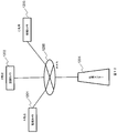
- FIG. 13 shows a video conference system
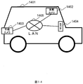
- FIG. 14 shows an example of an in-vehicle camera system.
- 1201, 1202, and 1203 are monitoring cameras installed at points A, B, and C, respectively
- 1204 is a monitoring center that receives images captured by the monitoring cameras 1201, 1202, and 1203, and 1205 is an Internet line A wide area network (WAN). Images captured by the monitoring cameras 1201 to 1203 can be displayed on a monitor or the like in the monitoring center 1204 via the WAN 1205.
- FIG. 12 shows an example in which there are three surveillance cameras, the number of in-vehicle cameras may be two or less or four or more.
- the image encoding apparatus is mounted on, for example, the monitoring cameras 1201 to 1203.
- the image encoding device performs an encoding process, which will be described later, on an input image input via the lenses of the monitoring cameras 1201 to 1203, and the encoded input image is output to the WAN 1205.
- reference numerals 1301, 1302, and 1303 denote video conference systems installed at points A, B, and C, respectively, and 1304 denotes a WAN such as an Internet line. Images captured by the cameras of the video conference systems 1301 to 1303 can be displayed on monitors of the video conference systems 1301 to 1303 via the WAN 1304. Although FIG. 13 shows an example in which there are three video conference systems, the number of video conference systems may be two or four or more.
- the image encoding apparatus is mounted on, for example, cameras of video conference systems 1301 to 1303.
- the image encoding device performs an encoding process, which will be described later, on an input image input through the camera lens of the video conference systems 1301 to 1303, and the encoded input image is output to the WAN 1305.
- reference numeral 1401 denotes an automobile
- 1402 and 1403 denote in-vehicle cameras mounted on the automobile 1401
- 1404 denotes a monitor for displaying images captured by the in-vehicle cameras 1402 and 1403
- 1405 denotes a local area network (LAN) in the automobile 1401. It is. Images captured by the in-vehicle cameras 1402 and 1403 can be displayed on the monitor 1404 via the LAN 1405.
- FIG. 14 shows an example in which two in-vehicle cameras are mounted, the number of in-vehicle cameras may be one or three or more.
- the image encoding apparatus is mounted on, for example, on-vehicle cameras 1402 and 1403.
- the image encoding device performs an encoding process, which will be described later, on an input image input via the lenses of the in-vehicle cameras 1402 and 1403, and the encoded input image is output to the LAN 1405.
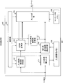
- FIG. 1 is an example of a configuration diagram of an image encoding device.
- the image encoding apparatus 100 includes an input image writing unit 101, an input image complexity calculating unit 102, an input image memory 103, an encoding unit image reading unit 104, an encoding unit 105, an encoding memory 106, and an encoding unit complexity calculation.
- QP quantization parameter
- the input image writing unit 101 performs a process of writing the input images input in the raster scan order in the input image memory 103.
- the input image complexity calculator 102 calculates the complexity using the input image before being written to the memory, and outputs the input image complexity.
- the complexity is an index indicating the difficulty of the pattern of the input image in the area corresponding to the target delay time, and is given by, for example, the variance value var described in (Equation 1).
- N represents the number of pixels in the horizontal direction to be calculated
- M represents the number of pixels in the vertical direction to be calculated
- x (ij) is a pixel value within the range of N ⁇ M pixels
- X is N ⁇ M pixels. Is an average value of the pixel values within the range.
- N and M are determined from the set target delay time.
- the target delay time is the processing time of the encoding process from when the image is input until the stream is output, and is controlled so that the generated code amount in this delay time unit is below a certain level.
- the target delay time is assumed to be about 1 to 50 ms for an in-vehicle network and about 100 ms for a video conference system, but the target delay time required may change depending on the situation.
- the input image memory 103 temporarily stores the input images input in the raster scan order, and is in a coding unit (in the case of H.264, a 16 pixel ⁇ 16 pixel macroblock (hereinafter referred to as “MB”)).
- MB 16 pixel ⁇ 16 pixel macroblock
- This memory may be an external memory such as SDRAM or an internal memory such as SRAM.
- the encoding unit reading unit 104 is a block that reads an MB image from the input image memory 103.
- the MB image read by the encoding unit reading unit 104 is supplied to the encoding unit 105 and the encoding unit complexity calculation unit 107.
- the encoding unit complexity calculation unit 107 calculates the complexity for each MB using the MB image, and outputs the encoding unit complexity. This is calculated using the same dispersion formula (Formula 1) as the input image complexity calculator 102.
- H In the case of H.264, since MB is 16 pixels ⁇ 16 pixels, N and M are both 16.
- the QP value calculation unit 108 outputs a QP value for each MB using the input image complexity, the encoding unit complexity, and the generated code amount generated when the encoding unit 105 actually encodes.
- the QP indicates a quantization parameter, that is, a quantization parameter, and the calculation method of the QP value will be described later with a specific example.
- the encoding unit 105 performs an encoding process using the MB image output from the encoding unit image reading unit 104 and the QP value output for each MB from the QP value calculation unit 108, and generates a stream.
- the encoding memory 106 is a memory for storing a reproduced image to be used for the prediction process, and may be either SDRAM or SRAM like the input image memory. Although the input image memory 103 and the encoding memory 106 are illustrated separately in FIG. 1, it is not necessary to separate them, and one SDRAM may be used.
- control unit 109 executes each processing block (input image writing unit 101, input image complexity calculation unit 102, encoding unit image reading unit 104, encoding unit 105, This block controls the coding unit complexity calculation unit 107 and the QP value calculation unit 108).
- processing block input image writing unit 101, input image complexity calculation unit 102, encoding unit image reading unit 104, encoding unit 105, This block controls the coding unit complexity calculation unit 107 and the QP value calculation unit 108.
- the control method will be described later with a specific example.
- a configuration including the input image complexity calculation unit 102 and the coding unit complexity calculation unit 107 is also simply referred to as an analysis unit.
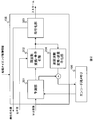
- the encoding unit 105 includes a prediction unit 201, a frequency conversion / quantization unit 202, an encoding unit 203, and an inverse frequency conversion / inverse quantization unit 204.
- the prediction unit 201 uses the MB image as an input, selects either the in-screen prediction or the inter-frame prediction, whichever is more efficient, and creates a predicted image. Thereafter, the generated predicted image and an error image obtained by subtracting the predicted image from the current image are output.
- In-screen prediction is a method of creating a prediction image using a reproduction image of an adjacent MB stored in the encoding memory 106, and inter-frame prediction is performed using a reproduction image of a past frame stored in the encoding memory 106. This is a method of creating a predicted image.
- the frequency transform / quantization unit 202 performs frequency transform on the error image, and then outputs a quantized coefficient obtained by quantizing the transform coefficient of each frequency component based on the quantization parameter given from the QP value calculating unit. .
- the encoding unit 203 encodes the quantized coefficient output from the frequency transform / quantization unit 202 and outputs a stream. Further, the generated code amount used by the QP value calculation unit 108 is output.
- the inverse frequency transform / inverse quantization unit 204 inversely quantizes the quantized coefficient to return it to the transform coefficient of each frequency component, and then performs an inverse frequency transform to generate an error image. Thereafter, a reproduction image is created by adding the prediction image output from the prediction unit 201 and stored in the encoding memory 106.
- the precondition is that an image of 1280 pixels ⁇ 720 pixels and 60 fps (frame per second) is encoded with a target delay time of 3.33 ms.
- FIG. 3 is a diagram in which an image of one frame (16.666 ms per frame because it is 60 fps) is divided into regions (region 1 to region 5) every target delay time 3.33 ms. All the areas have the same size, and the square blocks in the areas indicate MBs. Numbers described in the MB are assigned numbers in the processing order. In one area, the number of horizontal MBs is 80, the number of vertical MBs is 9, and the total number of MBs is 720. For each area, processing is performed so as to improve the image quality while keeping the generated code amount constant.
- each processing block (input image writing unit 101, input image complexity calculating unit 102, encoding unit image reading unit 104, encoding unit 105, encoding unit complexity calculating unit 107, QP
- the timing diagram which showed the processing timing of the value calculation part 108, the prediction part 201, the frequency conversion and quantization part 202, and the encoding part 203) is shown.
- the horizontal axis indicates time, and the vertical axis indicates each processing block, so that it can be understood which region or MB is processed at which timing for each processing block.
- the control of the processing timing is performed by the control unit 109 shown in FIG.
- Each process of the encoding unit 105 is a pipeline process for each MB as shown in FIG.
- pipeline processing is a technique for performing high-speed processing by dividing the encoding processing for each MB into a plurality of stages (stages) and processing the processes in each stage in parallel.
- the input image writing process of the input image writing unit 101 and the input image complexity calculating process of the input image complexity calculating unit 102 are performed in parallel.
- the encoding unit image reading unit 104 performs the encoding unit image reading process and outputs the encoded unit image to the encoding unit 105 and the encoding unit complexity calculation unit 107.
- the encoding unit complexity calculation unit 107 calculates the encoding unit complexity.
- the QP calculation process of the QP value calculation unit 108 and the prediction process of the prediction unit 201 are performed in parallel. Further, the frequency conversion / quantization unit 202 performs frequency conversion / quantization processing using the QP value calculated in the previous QP value calculation processing. Finally, the encoding unit 203 performs an encoding process and outputs a stream.
- the target delay time can be changed by changing the region size corresponding to the target delay time and changing the start timing of the encoding process.
- FIG. 5 is a diagram showing the internal details of the QP value calculation unit 108, and includes a base QP calculation unit 501, an MB (macroblock) QP calculation unit 502, and a QP calculation unit 503.
- the base QP calculation unit 501 is a process executed only when straddling regions (region 1 to region 5), and outputs the base QP of the region to be processed next using the input image complexity and the code amount.
- This base QP is given by (Equation 2) below.
- QP ave is the average QP value of the previous region
- bitrate is the generated code amount of the previous region
- target_bitrate is the target code amount of the next region
- ⁇ is a coefficient
- var next is the input image complexity of the next region
- Var pre indicate the input image complexity of the previous area.
- the MBQP calculation unit 502 is a process executed for each MB, and outputs MBQP from the encoding unit complexity and the input image complexity.
- This MBQP is given by (Equation 3).
- ⁇ represents a coefficient
- ⁇ represents a limiter value
- this process increases the MBQP of a complex picture with a large amount of generated code and reduces the MBQP of a flat picture with a small code amount to be generated. It also has the effect of smoothing the generated code amount for each.
- the QP calculation unit 503 calculates the QP value using the formula described in (Formula 4).
- the generated code amount in the base QP calculation unit 501 of the QP value calculation unit 108 is made constant, and the pattern in the MBQP calculation unit 502 of the QP value calculation unit 108 is determined.
- the QP value By controlling the QP value, it is possible to achieve high image quality while keeping the generated code amount for each target delay time constant.
- the configuration of the first embodiment is also effective when changing the target delay time during encoding or for each application.
- the encoding unit complexity for each encoding unit in parallel with the calculation of the input image complexity in the input image complexity calculation unit 102 the encoding unit complexity for the number of MBs in the target delay time region The degree needs to be recorded in a memory (in the example of the first embodiment, a memory of 720 MB is necessary).
- the pipeline processing delay (first embodiment) is calculated.
- it since it is used in the next stage, it is sufficient to have a memory of 1 MB), and it is sufficient to have a fixed memory regardless of the target delay time. This is particularly effective when encoding a large image size such as a 4k8k size because a small fixed amount of memory is sufficient.
- this configuration can be realized without changing the pipeline processing during encoding, and there is no delay in encoding processing due to the introduction of this processing.
- the target delay time of one frame or less has been described as an example.
- the target delay time may be set as late as the memory capacity permits.
- the bit distribution can be performed after analyzing three input images, so that high image quality can be realized.
- H.264 An example of H.264 is given, but it may be a moving image coding method (MPEG2, next-generation moving image coding method HEVC (H.265), etc.) having a parameter capable of changing the image quality for each coding unit. For example, the same effect can be obtained by using this configuration.
- MPEG2 next-generation moving image coding method HEVC (H.265), etc.
- any index indicating the complexity of the image can be used, such as the sum of difference values from adjacent pixels and the sum of edge detection filters (Sobel filter, Laplacian filter, etc.). It is not limited to the variance value.
- the specific QP value determination method of the QP value calculation unit 108 has been described with reference to FIG. 5, but is not limited to this processing. It suffices if at least the input image complexity, coding unit complexity, and generated code amount can be used to achieve high image quality while keeping the generated code amount constant according to the target delay time.
- the area to be input to the target delay time The complexity may be calculated for each region smaller than the size of.
- the input image complexity is calculated for the area of 720 MB, but it is assumed that the input image complexity is calculated for each 1/3 240 MB area.
- the code amount correction QP term shown in (Equation 4 ′) can be added every 240 MB.
- the code amount correction QP is a value calculated every 240 MB, and is calculated based on the code amount generated immediately before 240 MB.
- the code amount correction QP value is set to a positive value, and conversely, when the generated code amount is smaller than the code amount desired to be constant, By making the code amount QP value a negative value, it is possible to increase the accuracy of making the generated code amount constant in the target delay time.
- the camera system in FIG. 6 includes an image transmission device 1000 and an image reception device 1100.
- the image transmission apparatus 1000 is an in-vehicle camera, for example, and includes an imaging unit 1001 that converts light into a digital image, and an image encoding unit 1002 that encodes a digital image output from the imaging unit 1001 and generates a stream.
- the network IF 1003 is configured to packetize the encoded stream and output it on the network.
- the image receiving apparatus 1100 is, for example, a car navigation system, and receives a packet transmitted from the video transmitting apparatus 1000 and converts it into a stream, and generates a reproduction image by decoding the stream output from the network IF 1101
- a voice output unit 1105 is provided to output a voice and notify the driver when the result shows a dangerous state.
- FIG. 7 The configuration diagram of the image encoding device 1002 capable of improving the performance of the image recognition processing when performing the image recognition processing on the reproduced image is shown in FIG. 7 taking the configuration of the in-vehicle network camera system of FIG. 6 as an example.
- the description of the components having the same functions as those already described with reference to FIG. 1 is omitted.
- the encoding unit feature amount extraction unit 110 extracts an image feature amount from the MB image, and outputs the encoding unit image feature amount.
- a configuration including the input image complexity calculation unit 102, the coding unit complexity calculation unit 107, and the coding unit feature amount extraction unit is also simply referred to as an analysis unit.
- FIG. 8 shows the internal configuration of the QP value calculation unit 111. Description of portions having the same functions as those of the QP value calculation unit 108 in FIG. 5 having the same reference numerals shown in FIG.
- a difference from FIG. 5 is a feature QP calculation unit 504 and a QP calculation unit 505.
- the feature QP calculation unit 504 outputs a feature QP according to the size of the feature amount from the encoded unit image feature amount.
- the QP calculation unit 505 calculates a QP value by an expression given by (Expression 5) in which not only the base QP and MBQP but also the feature QP is added.
- the coding unit feature amount extraction unit 110 extracts white line feature amounts necessary for white line recognition. Specifically, the difference value between the adjacent pixels is calculated, and when there are consecutive difference values of the same step on the straight line, the white line feature amount (0, 1, 2) that increases the feature amount is obtained.
- the coding unit image feature amount is output as follows: the higher the value, the higher the possibility of a white line). Further, the feature QP calculation unit 504 determines the feature quantity QP from the three levels of white line feature quantities based on the table of FIG.
- the feature quantity QP may be determined using a mathematical expression such as a linear function or a Log function.
- the example which used the difference value with an adjacent pixel was described for the feature-value extraction, the result of having prepared the image of the basic pattern which can search a designated picture beforehand, and performing pattern matching with the basic pattern Any index value can be used as long as it is possible to determine a target whose image quality is to be improved, such as determining the feature quantity QP using (similarity).
- the feature amount may be calculated in an area calculated by the input image complexity calculation unit 102. .
- FIG. 10 shows an example in which the target delay time is changed according to the application, taking the in-vehicle network camera system of FIG. 6 as an example.
- Applications include rear obstacle detection during parking, white line departure warning during high-speed driving, and sign recognition during urban driving.
- the application to be used changes depending on the speed of the car. Therefore, the target delay time may be changed according to the speed of the car.
- ⁇ Obstacle detection during parking is assumed to be used at a speed of 20 km / h or less. Since the speed is low, there is little change in the image for each frame, so a low delay of 10 ms or less is not necessary, and the target delay time is 33.3 ms. Therefore, the image quality can be improved using the analysis result for one frame.
- the white line departure warning during high speed driving is assumed to be used at a speed of 100 km / h or more. Therefore, it is considered that the image changes greatly every frame. If the delay time is large, even if image recognition processing is performed and a dangerous state is detected, it is important that the target delay time is as short as 1 ms because there is a possibility that an accident has already occurred.
- the sign recognition when traveling in urban areas is a moderate speed of 40 km to 80 km per hour, so it does not go up to 1 ms, but it is necessary to shorten the target delay time to some extent, so it is 10 ms.
- the image encoding device when the image encoding device is applied to the in-vehicle network camera system, the image feature focused by the image recognition processing algorithm of the image recognition unit 1104 of the image receiving device 1100 is the encoding unit feature of the image transmitting device 1000.
- the extraction unit 110 simply extracts the feature amount, and the QP value calculation unit 111 lowers the QP value of the corresponding MB. It is possible to realize an image encoding device capable of improving the performance of recognition processing.
- the imaging unit 1001 may be replaced with a storage device such as a recorder.
- the transmission is performed while considering the delay in image transmission by setting the target delay time according to the application to be used. It becomes possible to improve the image quality.
Landscapes
- Engineering & Computer Science (AREA)
- Multimedia (AREA)
- Signal Processing (AREA)
- Automation & Control Theory (AREA)
- Physics & Mathematics (AREA)
- General Physics & Mathematics (AREA)
- Human Computer Interaction (AREA)
- Transportation (AREA)
- Mechanical Engineering (AREA)
- Theoretical Computer Science (AREA)
- Compression Or Coding Systems Of Tv Signals (AREA)
Abstract
Description
本願は上記課題を解決する手段を複数含んでいるが、その一例を挙げるならば、
入力される画像を解析する解析ステップと、解析ステップの解析結果を用いて量子化パラメータを算出する量子化パラメータ算出ステップと、量子化パラメータ算出ステップで算出した量子化パラメータを用いて入力される画像のエンコードを行うエンコードステップと、を有し、解析ステップで解析する第1の領域の大きさが可変であることを特徴とする。






101 入力画像書込み部
102 入力画像複雑度計算部
103 入力画像用メモリ
104 符号化単位画像読込み部
105 エンコード部
106 エンコード用メモリ
107 符号化単位複雑度計算部
108 QP値計算部
109 制御部
201 予測部
202 周波数変換・量子化部
203 符号化部
204 逆周波数変換・逆量子化部
501 ベースQP計算部
502 MBQP計算部
503 QP値算出部
1000 画像送信装置
1001 撮像部
1002 画像符号化部
1003 ネットワークIF
1100 画像受信装置
1101 ネットワークIF
1102 画像復号部
1103 表示部
1104 画像認識部
1105 音声出力部
1201 監視カメラ
1202 監視カメラ
1203 監視カメラ
1204 監視センター
1205 WAN
1301 テレビ会議システム
1302 テレビ会議システム
1303 テレビ会議システム
1304 WAN
1401 自動車
1402 車載カメラ
1403 車載カメラ
1404 モニタ
1405 LAN
Claims (14)
- 入力される画像を解析する解析ステップと、
前記解析ステップの解析結果を用いて量子化パラメータを算出する量子化パラメータ算出ステップと、
前記量子化パラメータ算出ステップで算出した量子化パラメータを用いて入力される画像のエンコードを行うエンコードステップと、を有し、
前記解析ステップで解析する第1の領域の大きさが可変であることを特徴とする符号化方法。 - 請求項1の符号化方法であって、
前記第1の領域の大きさは、前記符号化方法を用いて行われる映像伝送において設定される遅延時間に基づいて変化することを特徴とする符号化方法。 - 請求項1または2の符号化方法であって、
前記第1の領域の大きさは入力される画像の1フレームの大きさよりも小さいことを特徴とする符号化方法。 - 請求項1~3のいずれかの符号化方法であって、
前記解析ステップは、
前記第1の領域を解析する第1の解析ステップと、
前記第1の領域の一部である第2の領域を解析する第2の解析ステップと、を含むことを特徴とする符号化方法。 - 請求項4の符号化方法であって、
前記第1の解析ステップでは前記第1の領域の画像の複雑度を計算し、
前記第2の解析ステップでは前記第2の領域の画像の複雑度を計算することを特徴とする符号化方法。 - 請求項4または5の符号化方法であって、
前記解析ステップは、前記第2の領域の画像の特徴量を抽出する第3の解析ステップを含むことを特徴とする符号化方法。 - 請求項4~6のいずれかの符号化方法であって、
前記第2の領域は、前記エンコードステップにおけるエンコードの単位である符号化単位の領域であることを特徴とする符号化方法。 - 入力される画像を解析する解析部と、
前記解析部の解析結果を用いて量子化パラメータを算出する量子化パラメータ算出部と、
前記量子化パラメータ算出部で算出した量子化パラメータを用いて入力される画像のエンコードを行うエンコード部と、を有し、
前記解析部解析する第1の領域の大きさが可変であることを特徴とする符号化装置。 - 請求項8の符号化装置であって、
前記第1の領域の大きさは、前記符号化装置を用いて行われる映像伝送において設定される遅延時間に基づいて変化することを特徴とする符号化装置。 - 請求項8または9の符号化装置であって、
前記第1の領域の大きさは、入力される画像の1フレームの大きさよりも小さいことを特徴とする符号化装置。 - 請求項8~10のいずれかの符号化装置であって、
前記解析部は、
前記第1の領域を解析する第1の解析部と、
前記第1の領域の一部である第2の領域を解析する第2の解析部と、を含むことを特徴とする符号化装置。 - 請求項11の符号化装置であって、
前記第1の解析部は前記第1の領域の画像の複雑度を計算し、
前記第2の解析部は前記第2の領域の画像の複雑度を計算することを特徴とする符号化装置。 - 請求項11または12の符号化装置であって、
前記解析部は、前記第2の領域の画像の特徴量を抽出する第3の解析部を含むことを特徴とする符号化装置。 - 請求項11~13のいずれかの符号化装置であって、
前記第2の領域は、前記エンコード部におけるエンコードの単位である符号化単位の領域であることを特徴とする符号化装置。
Priority Applications (4)
| Application Number | Priority Date | Filing Date | Title |
|---|---|---|---|
| PCT/JP2013/058487 WO2014155471A1 (ja) | 2013-03-25 | 2013-03-25 | 符号化方法および符号化装置 |
| US14/653,483 US10027960B2 (en) | 2013-03-25 | 2013-03-25 | Coding method and coding device |
| JP2015507704A JP6084682B2 (ja) | 2013-03-25 | 2013-03-25 | 符号化方法および符号化装置 |
| CN201380067188.5A CN104871544B (zh) | 2013-03-25 | 2013-03-25 | 编码方法以及编码装置 |
Applications Claiming Priority (1)
| Application Number | Priority Date | Filing Date | Title |
|---|---|---|---|
| PCT/JP2013/058487 WO2014155471A1 (ja) | 2013-03-25 | 2013-03-25 | 符号化方法および符号化装置 |
Publications (1)
| Publication Number | Publication Date |
|---|---|
| WO2014155471A1 true WO2014155471A1 (ja) | 2014-10-02 |
Family
ID=51622567
Family Applications (1)
| Application Number | Title | Priority Date | Filing Date |
|---|---|---|---|
| PCT/JP2013/058487 Ceased WO2014155471A1 (ja) | 2013-03-25 | 2013-03-25 | 符号化方法および符号化装置 |
Country Status (4)
| Country | Link |
|---|---|
| US (1) | US10027960B2 (ja) |
| JP (1) | JP6084682B2 (ja) |
| CN (1) | CN104871544B (ja) |
| WO (1) | WO2014155471A1 (ja) |
Families Citing this family (1)
| Publication number | Priority date | Publication date | Assignee | Title |
|---|---|---|---|---|
| US10356408B2 (en) * | 2015-11-27 | 2019-07-16 | Canon Kabushiki Kaisha | Image encoding apparatus and method of controlling the same |
Citations (6)
| Publication number | Priority date | Publication date | Assignee | Title |
|---|---|---|---|---|
| JPH0541806A (ja) * | 1991-08-06 | 1993-02-19 | Olympus Optical Co Ltd | 画像記録装置 |
| JPH08102947A (ja) * | 1994-09-29 | 1996-04-16 | Sony Corp | 画像信号符号化方法及び画像信号符号化装置 |
| JPH11164305A (ja) * | 1997-04-24 | 1999-06-18 | Mitsubishi Electric Corp | 動画像符号化方法、動画像符号化装置および動画像復号装置 |
| JP2006519565A (ja) * | 2003-03-03 | 2006-08-24 | コーニンクレッカ フィリップス エレクトロニクス エヌ ヴィ | ビデオ符号化 |
| JP2009246540A (ja) * | 2008-03-28 | 2009-10-22 | Ibex Technology Co Ltd | 符号化装置、符号化方法および符号化プログラム |
| JP2010141659A (ja) * | 2008-12-12 | 2010-06-24 | Sony Corp | 情報処理装置および方法 |
Family Cites Families (7)
| Publication number | Priority date | Publication date | Assignee | Title |
|---|---|---|---|---|
| JPH0797753B2 (ja) | 1989-01-24 | 1995-10-18 | 日本ビクター株式会社 | 符号化出力データ量の制御方式 |
| TW388843B (en) * | 1997-04-24 | 2000-05-01 | Mitsubishi Electric Corp | Moving image encoding method, moving image encoder and moving image decoder |
| JP3324551B2 (ja) | 1999-03-18 | 2002-09-17 | 日本電気株式会社 | 画像信号の符号化制御装置 |
| JP3893344B2 (ja) * | 2002-10-03 | 2007-03-14 | 松下電器産業株式会社 | 画像符号化方法および画像符号化装置 |
| JP4257655B2 (ja) * | 2004-11-04 | 2009-04-22 | 日本ビクター株式会社 | 動画像符号化装置 |
| JP5128389B2 (ja) * | 2008-07-01 | 2013-01-23 | 株式会社日立国際電気 | 動画像符号化装置及び動画像符号化方法 |
| CN105872541B (zh) * | 2009-06-19 | 2019-05-14 | 三菱电机株式会社 | 图像编码装置、图像编码方法及图像解码装置 |
-
2013
- 2013-03-25 US US14/653,483 patent/US10027960B2/en active Active
- 2013-03-25 CN CN201380067188.5A patent/CN104871544B/zh active Active
- 2013-03-25 WO PCT/JP2013/058487 patent/WO2014155471A1/ja not_active Ceased
- 2013-03-25 JP JP2015507704A patent/JP6084682B2/ja active Active
Patent Citations (6)
| Publication number | Priority date | Publication date | Assignee | Title |
|---|---|---|---|---|
| JPH0541806A (ja) * | 1991-08-06 | 1993-02-19 | Olympus Optical Co Ltd | 画像記録装置 |
| JPH08102947A (ja) * | 1994-09-29 | 1996-04-16 | Sony Corp | 画像信号符号化方法及び画像信号符号化装置 |
| JPH11164305A (ja) * | 1997-04-24 | 1999-06-18 | Mitsubishi Electric Corp | 動画像符号化方法、動画像符号化装置および動画像復号装置 |
| JP2006519565A (ja) * | 2003-03-03 | 2006-08-24 | コーニンクレッカ フィリップス エレクトロニクス エヌ ヴィ | ビデオ符号化 |
| JP2009246540A (ja) * | 2008-03-28 | 2009-10-22 | Ibex Technology Co Ltd | 符号化装置、符号化方法および符号化プログラム |
| JP2010141659A (ja) * | 2008-12-12 | 2010-06-24 | Sony Corp | 情報処理装置および方法 |
Also Published As
| Publication number | Publication date |
|---|---|
| JPWO2014155471A1 (ja) | 2017-02-16 |
| CN104871544A (zh) | 2015-08-26 |
| JP6084682B2 (ja) | 2017-02-22 |
| US10027960B2 (en) | 2018-07-17 |
| US20150350649A1 (en) | 2015-12-03 |
| CN104871544B (zh) | 2018-11-02 |
Similar Documents
| Publication | Publication Date | Title |
|---|---|---|
| US10582196B2 (en) | Generating heat maps using dynamic vision sensor events | |
| US9706203B2 (en) | Low latency video encoder | |
| US10212456B2 (en) | Deblocking filter for high dynamic range (HDR) video | |
| CN103650504B (zh) | 基于图像捕获参数对视频编码的控制 | |
| US8457205B2 (en) | Apparatus and method of up-converting frame rate of decoded frame | |
| US8493499B2 (en) | Compression-quality driven image acquisition and processing system | |
| US11102475B2 (en) | Video encoding device, operating methods thereof, and vehicles equipped with a video encoding device | |
| US12316908B2 (en) | System and method to minimize repetitive flashes in streaming media content | |
| US20130195206A1 (en) | Video coding using eye tracking maps | |
| EP3648460A1 (en) | Method and apparatus for controlling encoding resolution ratio | |
| US11924424B2 (en) | Method and device for transmitting block division information in image codec for security camera | |
| US12563238B2 (en) | Encoding of pre-processed image frames | |
| WO2012160626A1 (ja) | 画像圧縮装置、画像復元装置、及びプログラム | |
| JP6084682B2 (ja) | 符号化方法および符号化装置 | |
| EP4672738A1 (en) | SELECTIVE FRAME PROCESSING IN A BLOW-BASED CODING PIPELINE | |
| Benjak et al. | Deferred demosaicking: efficient first-person view drone video encoding | |
| WO2023132163A1 (ja) | 映像圧縮方法、映像圧縮装置、コンピュータプログラム、及び映像処理システム | |
| CN111901605B (zh) | 视频处理方法、装置、电子设备及存储介质 | |
| EP4637138A1 (en) | Adaptive coding tool selection with content classification | |
| US11716475B2 (en) | Image processing device and method of pre-processing images of a video stream before encoding | |
| US20250254329A1 (en) | Video encoding with content adaptive resolution decision | |
| US11089308B1 (en) | Removing blocking artifacts in video encoders | |
| Shirahase et al. | Video Transfer Method Suitable for Object Detection in the Cloud | |
| Isnardi et al. | Salience-based compression: providing FMV over low-bit rate channels |
Legal Events
| Date | Code | Title | Description |
|---|---|---|---|
| 121 | Ep: the epo has been informed by wipo that ep was designated in this application |
Ref document number: 13879706 Country of ref document: EP Kind code of ref document: A1 |
|
| ENP | Entry into the national phase |
Ref document number: 2015507704 Country of ref document: JP Kind code of ref document: A |
|
| WWE | Wipo information: entry into national phase |
Ref document number: 14653483 Country of ref document: US |
|
| NENP | Non-entry into the national phase |
Ref country code: DE |
|
| 122 | Ep: pct application non-entry in european phase |
Ref document number: 13879706 Country of ref document: EP Kind code of ref document: A1 |