WO2014148347A1 - 多孔質面形成方法,光化学反応器の製造方法及び光化学反応器 - Google Patents
多孔質面形成方法,光化学反応器の製造方法及び光化学反応器 Download PDFInfo
- Publication number
- WO2014148347A1 WO2014148347A1 PCT/JP2014/056652 JP2014056652W WO2014148347A1 WO 2014148347 A1 WO2014148347 A1 WO 2014148347A1 JP 2014056652 W JP2014056652 W JP 2014056652W WO 2014148347 A1 WO2014148347 A1 WO 2014148347A1
- Authority
- WO
- WIPO (PCT)
- Prior art keywords
- glass tube
- particles
- silica particles
- photochemical reactor
- silica
- Prior art date
- Legal status (The legal status is an assumption and is not a legal conclusion. Google has not performed a legal analysis and makes no representation as to the accuracy of the status listed.)
- Ceased
Links
Images








Classifications
-
- B—PERFORMING OPERATIONS; TRANSPORTING
- B01—PHYSICAL OR CHEMICAL PROCESSES OR APPARATUS IN GENERAL
- B01J—CHEMICAL OR PHYSICAL PROCESSES, e.g. CATALYSIS OR COLLOID CHEMISTRY; THEIR RELEVANT APPARATUS
- B01J19/00—Chemical, physical or physico-chemical processes in general; Their relevant apparatus
- B01J19/08—Processes employing the direct application of electric or wave energy, or particle radiation; Apparatus therefor
- B01J19/12—Processes employing the direct application of electric or wave energy, or particle radiation; Apparatus therefor employing electromagnetic waves
-
- B—PERFORMING OPERATIONS; TRANSPORTING
- B01—PHYSICAL OR CHEMICAL PROCESSES OR APPARATUS IN GENERAL
- B01J—CHEMICAL OR PHYSICAL PROCESSES, e.g. CATALYSIS OR COLLOID CHEMISTRY; THEIR RELEVANT APPARATUS
- B01J35/00—Catalysts, in general, characterised by their form or physical properties
- B01J35/30—Catalysts, in general, characterised by their form or physical properties characterised by their physical properties
- B01J35/39—Photocatalytic properties
-
- C—CHEMISTRY; METALLURGY
- C01—INORGANIC CHEMISTRY
- C01B—NON-METALLIC ELEMENTS; COMPOUNDS THEREOF; METALLOIDS OR COMPOUNDS THEREOF NOT COVERED BY SUBCLASS C01C
- C01B33/00—Silicon; Compounds thereof
- C01B33/113—Silicon oxides; Hydrates thereof
- C01B33/12—Silica; Hydrates thereof, e.g. lepidoic silicic acid
- C01B33/126—Preparation of silica of undetermined type
-
- B—PERFORMING OPERATIONS; TRANSPORTING
- B01—PHYSICAL OR CHEMICAL PROCESSES OR APPARATUS IN GENERAL
- B01J—CHEMICAL OR PHYSICAL PROCESSES, e.g. CATALYSIS OR COLLOID CHEMISTRY; THEIR RELEVANT APPARATUS
- B01J2219/00—Chemical, physical or physico-chemical processes in general; Their relevant apparatus
- B01J2219/08—Processes employing the direct application of electric or wave energy, or particle radiation; Apparatus therefor
- B01J2219/0873—Materials to be treated
- B01J2219/0892—Materials to be treated involving catalytically active material
Definitions
- the present invention relates to a porous surface forming method, a photochemical reactor manufacturing method, and a photochemical reactor suitable for use in manufacturing a fluid treatment apparatus and the like.
- Patent Document 1 discloses a purifier
- Patent Document 2 discloses a water treatment device. Is disclosed.
- the purification device disclosed in Patent Document 1 includes an outer tube made of a material that transmits ultraviolet rays such as glass and the like, and an outer tube that is open at both ends, and is accommodated in the outer tube.
- the bead surface is filled with a photocatalyst coated with anatase-type titanium dioxide, and an inner tube that forms a treatment space to which treated water is supplied, glass filters provided at both ends of the outer tube, and an outer tube
- An ultraviolet lamp that irradiates ultraviolet rays arranged in the vicinity and a reflector that reflects the ultraviolet rays emitted from the ultraviolet lamp toward the outer tube are configured.
- the treatment device is a cylindrical vessel that is mounted on the rotation support shaft of the drive device, and is installed to rotate at a speed of about 1 to 5 revolutions per minute around the central axis.
- One of the pipes is provided with an introduction pipe for water to be treated, and the other is provided with a discharge pipe, so that the water to be treated is introduced and discharged so as to have a predetermined circulation amount in the treatment tank. .
- each water purifier increases the contact area of titanium dioxide (photocatalyst) to the water to be treated by using a large number of photocatalysts formed by coating titanium dioxide on the surface of granules formed of glass material. Increases processing capacity (processing efficiency).
- processing capacity processing efficiency
- Patent Document 2 since the treatment tank is rotated at a speed of about 1 to 5 revolutions per minute, the photocatalyst contained in the treatment tank is agitated randomly. Therefore, the point that all the photocatalysts can be activated on average but the photocatalyst behind the photocatalyst cannot be activated is the same as in the case of the cited document 1, which is insufficient from the viewpoint of increasing the irradiation area of ultraviolet rays.
- a large processing tank and a driving device for rotating the processing tank are required, which increases the cost and size of the entire apparatus and requires the use of electric power. Therefore, it is inferior in versatility, such as limited places where it can be used.
- This photoreactor and its manufacturing method increase the contact area of the surface of the granule to the fluid, and further increase the irradiation area to the surface of the granule, thereby increasing the processing capacity (processing efficiency) for the fluid and reducing the amount.
- the purpose is to make it easy to manufacture with the number of parts, to reduce the overall cost, to make it compact and compact, and to improve energy saving and versatility.
- a photoreactor configured to accommodate a large number of formed granules and to allow fluid to flow in the glass tube, and a contact portion between the glass tube and the particles, and a contact portion between the particles Are formed as a welded surface having a predetermined area, so that a light guide path continuous through the welded surface is provided on the glass tube and the granule to constitute a photoreactor.
- the manufacturing method also includes a method of heating the glass tube filled with the granules at a predetermined heating temperature after filling the granules into the glass tube, and a contact portion between the glass tube and the granules, and the granules. Welding surfaces each having a predetermined area are generated at the abutting portions between them, and a light guide path that is continuous through the welding surface is provided on the glass tube and the granules.
- the contact area of the particle surface with respect to the fluid can be increased and the irradiation area with respect to the particle surface can be further increased.
- the internal surface area is about 4.5 times that of a simple glass tube, and
- the photochemical reaction activity (decomposition reaction) increases approximately 6.3 times, the activity is insufficient from the viewpoint of ensuring practicality, and there is room for further improvement in order to increase the processing capacity.
- the contact area of the particle surface with the fluid since it is necessary to further increase the contact area of the particle surface with the fluid, the overall size and cost tend to be sacrificed. That is, when increasing the contact area of the particle surface, the contact area can be increased by taking measures such as increasing the amount of particles or lengthening the glass tube, but the overall size and flowability are increased. It tends to cause a decline in In the end, it is not easy to avoid the increase in size and maintain the flowability while increasing the processing capacity.
- the present invention aims to provide a method for forming a porous surface, a method for producing a photochemical reactor, and a photochemical reactor that solve the problems existing in the background art.
- the porous surface forming method of the present invention provides a silica dispersion Ag containing alkoxysilane when providing the porous surface Ef on the surface of the object G in order to solve the above-described problems.
- a number of silica particles Bm... Having a predetermined particle diameter are added, and a surface forming agent E is generated by using a sol-gel method, and the surface forming agent G is applied to the surface of the object G, and then the surface.
- a porous surface Ef is provided by heat-treating the forming agent E at a predetermined fixing temperature and fixing the silica particles Bm to the surface of the object G in a state where a part of the silica dispersion Ag remains. It is characterized by.
- the silica dispersion Ag contains a plurality of second silicas having a particle diameter in the range of 1 to 300 [nm] which is smaller than the silica particles (first silica particles) Bm. Particles Bs can be included.
- the manufacturing method of the photochemical reactor which concerns on this invention fills the inside of the glass tube 2 with many granule 3 ... formed with the glass raw material in order to solve the subject mentioned above, Then, the said granule 3 ... By heating the glass tube 2 filled with a predetermined melting temperature, a contact area between the glass tube 2 and the particles 3... And a contact portion between the particles 3.
- the photochemical reactor 1 in which the light guide C is formed on the glass tube 2 and the granule 3 through the welding surface J, and the like.
- a large number of silica particles Bm selected to have a particle size of 1 [ ⁇ m] or more and a particle size of 15 [%] or less with respect to the outer diameter of the granules 3 are added to the dispersion Ag.
- the surface forming agent E is produced using a sol-gel method, After the forming agent E is applied to the inner surfaces 2f, 3f, etc. of the glass tube 2, the surface forming agent E is heat-treated at a predetermined fixing temperature, and the silica particles Bm are converted into a part of the silica dispersion Ag. In this state, a porous surface Ef is provided by adhering to the inner surfaces 2f... 3f.
- the silica dispersion Ag contains a plurality of second silicas having a particle diameter in the range of 1 to 300 [nm] which is smaller than the silica particles (first silica particles) Bm. Particles Bs can be included. Moreover, the photocatalyst layer 4 ... can be provided on the surface of the porous surface Ef.
- the photochemical reactor 1 fills the inside of the glass tube 2 with a large number of particles 3 formed of a glass material, and a contact portion between the glass tube 2 and the particles 3.
- the light guide path C which continues through the welding surface J ... is provided in the glass tube 2 and the granule 3 ... by providing the welding surface J ... which each has a predetermined area in the contact part between the bodies 3 ....
- a porous surface Ef is provided by fixing a number of silica particles Bm.
- the glass tube 2 can be used in the fluid processing apparatus M in which one end of the glass tube 2 becomes the inlet 2i of the processing fluid La and the other end becomes the outlet 2e of the processing fluid Lb. It is also possible to irradiate light from the external light emitting unit 5 to the peripheral surface of the glass tube 2.
- the photochemical reactor 1 according to the present invention configured as described above introduces a hierarchical structure to the inner surfaces 2f, 3f, ... desired in the flow path formed inside the glass tube 2, and has a main channel of nanometer order and a nanometer.
- the internal surface area can be increased while ensuring a practical distribution amount. Therefore, when the light irradiated on the peripheral surface of the glass tube 2 is guided to the porous layer of the inner surfaces 2f, 3f..., The intensity of the light is 1 / compared with the intensity on the peripheral surface of the glass tube 2. It is conceivable that the pressure drops to about 1000.
- the photochemical reactor 1 In general, in a photochemical reaction, when the concentration of an excited state is increased, the light utilization rate (quantum efficiency or quantum yield) is significantly reduced due to deactivation due to interaction between excited states. On the other hand, if the light intensity is lowered, the reaction rate of the photochemical reactor 1 is lowered, so that the reaction yield and the quantum efficiency are in a trade-off relationship.
- the photochemical reactor 1 according to the present invention light entering from the peripheral surface of the glass tube 2 is guided from the millimeter order glass to the micrometer order glass, and the fluid (reaction solution) flowing through the flow path is on the micrometer order.
- porous channel porous surface Ef
- a wide active surface is ensured while ensuring a mass transfer rate. Therefore, for example, if the photocatalyst layer 4..., That is, nanometer-order photocatalyst ultrafine particles are supported on the surface of the porous surface Ef in the photochemical reactor 1, it can be used as a photocatalyst reactor with increased activity and processing speed. .
- the silica dispersion Ag containing alkoxysilane has a particle size of 1 [ ⁇ m] or more and a particle size of 15 [%] or less with respect to the outer diameter of the granules 3.
- a large number of silica particles Bm are added, and a surface forming agent E is generated using a sol-gel method.
- the surface forming agent E is applied to the surface of the object G, the surface forming agent E Since the porous surface Ef is provided by fixing the silica particles Bm... To the surface of the object G in a state where a part of the silica dispersion Ag remains, the porous surface Ef is provided.
- the substantial area of the surface can be increased dramatically with little major geometric change of the surface in the body G.
- the method for producing a photochemical reactor is that the glass tube 2 is filled with a large number of granules 3 made of a glass material, and then the glass tube 2 filled with the granules 3 is used for predetermined melting. By performing heat treatment at a temperature, weld surfaces J each having a predetermined area are generated at the contact portion between the glass tube 2 and the particles 3 and the contact portion between the particles 3.
- the photochemical reactor 1 in which the tube 2 and the particles 3... Are provided with the continuous light guide C through the welding surface J..., The above-described porous structure is formed on the glass tube 2 and the particles 3. Since the surface forming method can be used, the contact area with the fluid flowing inside the glass tube 2 can be dramatically increased.
- the photochemical reaction activity of the fluid in contact with the inner surfaces 2f, 3f... Of the glass tube 2 is easily increased to about 1000 times that is practical compared to the inner peripheral surface of the glass tube 2 without the porous surface Ef. Can be made.
- the fixing function (bonding function) to the first silica particles Bm can be further increased, the surface of the formed body G, that is, the inner surface 2f of the glass tube 2, 3f, The first silica particles Bm can be more firmly and stably fixed.
- one end of the glass tube 2 becomes the inlet 2i of the fluid La to be processed and the other end is It is possible to easily construct the fluid processing apparatus M that becomes the outlet 2e of the processing fluid Lb, dramatically increase the processing capacity (processing efficiency) when purifying the fluid La to be processed, and further reduce the cost and reduce the size and size.
- the fluid processing apparatus M can be provided.
- the fluid processing apparatus M that functions more efficiently and effectively can be obtained. Can be easily obtained.
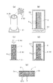
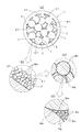
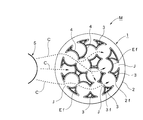
- a flowchart for explaining a processing procedure when producing a surface forming liquid used in the method for producing the photochemical reactor Schematic diagram of the process state for explaining the manufacturing method of the photochemical reactor, Basic cross-sectional configuration diagram including an extracted enlarged cross-sectional view of each part in the front view of the photochemical reactor, Action diagram of the photochemical reactor, Side cross-sectional view omitting a part of the photochemical reactor, Action explanatory diagram using the extracted enlarged cross-section of some particles of the photochemical reactor, Transmittance characteristics diagram for the light wavelength of the glass used in the same photochemical reactor, Light intensity characteristic diagram for light wavelength between particles in the same photochemical reactor, Side sectional view showing a part of a photochemical reactor according to a modified embodiment of the present invention, Side surface sectional drawing of the granule for demonstrating the manufacturing method of the photochemical reactor which concerns on other modified embodiment of this invention, Side surface sectional drawing of the one part gran
- SYMBOLS 1 Photochemical reactor, 2: Glass tube, 2i: Inlet, 2e: Outlet, 3 ...: Granule, 3f ...: The surface of a particle, 4 ...: Photocatalyst layer, 5: Light emission part, G: Formation Body, Ef: porous surface, Bm ...: silica particles (first silica particles), Bs ...: second silica particles, E: surface forming agent, Ag: silica dispersion, J ...: welding surface, C: light guide , La: fluid to be processed, Lb: processing fluid, M: fluid processing device
- a glass tube 2 and a large number of granules 3 that are used parts are prepared (step S1).
- the glass tube 2 and a large number of particles 3 constitute the object G in the present invention.
- the glass tube 2 is a single tube having a circular cross section, and is formed using heat-resistant glass such as Pyrex (registered trademark) glass. Therefore, the target glass tube 2 can be easily obtained by cutting the length of the long glass pipe having a predetermined diameter by the length to be used. If the cross-sectional shape of the glass tube 2 is formed in a circular shape, the most popular shape can be obtained, so that there is an advantage that it can be manufactured easily and at low cost.
- the inner diameter, the outer diameter, and the length of the glass tube 2 are not particularly limited, and the inner diameter of the illustrated glass tube 2 is selected to be 30 [mm].
- the granule 3 is formed into a spherical shape having the same diameter using a glass material.
- a glass material As the glass material of the granule 3, general-purpose soda glass, silica glass, and the like can be used as well as the above-described Pyrex (registered trademark) glass.
- Pyrex registered trademark
- a sphere (glass bead) having an outer diameter of 5 mm was used.
- the glass tube 2 and a large number of particles 3 are prepared, the glass tube 2 is erected on the substrate jig 21 as shown in FIG. To fill the inside of the glass tube 2 (step S2).
- the glass tube 2 filled with the granules 3 is accommodated in a heating furnace 23 that is heated by the heater 22, and a preset heating temperature (melting temperature) Th.
- Heat treatment is performed for a preset heating time Zh in a temperature environment of [° C.] (steps S3 and S4). Thereby, the surface of the glass tube 2 and the granule 3 ...
- the heating temperature Th [° C.] is preferably about 600 to 700 [° C.].
- the heating time Zh has elapsed, the glass tube 2 is taken out from the heating furnace 23 and cooled to room temperature by natural cooling (step S5). Thereby, the continuous light guide C is provided in the glass tube 2 and the granule 3 ... via the welding surface J ....
- the glass tube 2 filled with the granules 3 is heated at a predetermined heating temperature Th, so that the glass tube 2 and the granules 3. If a welding surface J having a predetermined area is generated at each of the abutting portions and the abutting portions between the granule bodies 3..., It can be manufactured very easily with a small number of parts. It is possible to realize cost reduction and downsizing and compactness, and since there is no need for a power unit or the like, there is an advantage of excellent energy saving and versatility.
- a surface forming agent E for providing a porous surface Ef is applied to the inner surfaces 2f, 3f.
- the inner surfaces 2f, 3f,... Of the glass tube 2 include the inner peripheral surface 2f of the glass tube 2, and the surfaces 3f,.
- the surface forming agent E to be used is prepared separately and prepared in advance (step S20). Since the use of the surface forming agent E becomes an important technical element of the present invention, hereinafter, a manufacturing method (Example) capable of obtaining the surface forming agent E will be described with reference to the flowchart shown in FIG. This will be specifically described.
- a silica-dispersed aqueous solution Ao is prepared as a main raw material (step S21).
- This silica-dispersed aqueous solution Ao is an aqueous solution containing a large number of silica particles Bs... Having a diameter of the order of nanometers, and in this embodiment, commercially available silica particles (second silica particles) Bs.
- An aqueous silica dispersion Ao (4.8 [wt%]) was used.
- the reason for using such silica particles Bs... Is to prevent color development due to spectroscopy by using non-crystalline silica particles (quartz).
- the particle size of the second silica particles Bs is preferably selected in the range of 1 to 300 [nm].
- silica-dispersed aqueous solution Ao second silica particles Bs having a particle diameter in the range of 1 to 300 [nm], which is sufficiently smaller than the first silica particles Bm used for porous formation described later.
- the fixing function (bonding function) to the first silica particles Bm can be further enhanced, so that the surface of the formed body G, that is, the inner surfaces 2f, 3f.
- the first silica particles Bm can be more firmly and stably fixed.
- step S22 and S23 the same amount of methanol is added to the prepared silica-dispersed aqueous solution Ao, and centrifugal separation is performed under the conditions of a rotational speed of 6000 [rpm] and a processing time of 30 [min].
- the centrifugal separation process is completed, the transparent supernatant is removed, and the residual liquid amount after the removal is halved (step S24).
- the same amount of methanol is added to the residual liquid from which the supernatant liquid has been removed, and stirring is performed (steps S25 and S26).
- step S27 When the shaking and stirring is completed, the centrifugal separation process is performed under the conditions of the rotational speed of 6000 [rpm] and the processing time of 30 [minutes] (step S27).
- step S28 When the centrifugation process is completed, the transparent supernatant is removed, and the remaining liquid amount after the removal is halved (step S28). Then, the processes in steps S25 to S28 are repeated a set number of times (in the example, 8 times) (step S29).
- 3 [wt%] gel-like silica dispersion is obtained by adding 60 [%] volume of methanol to the volume of the obtained silica dispersion and stirring with stirring. Ag is obtained (steps S30, S31, S32).
- the water content of the silica dispersion Ag obtained at this time is approximately 0.4 [wt%]. It is also possible to use a similar dispersion in which silica particles (second silica particles Bs). Are dispersed in an alcohol solvent. In this case, the processing steps of steps S22 to S32 described above can be omitted.
- TEOS tetraethoxysilane
- TEOS tetraethoxysilane
- TEOS is exemplified as an example of a silica precursor, that is, an alkoxysilane, and other silica precursors belonging to alkoxysilane such as tetramethoxysilane may be used. Therefore, the alkoxide used as the precursor is not limited. In addition, it is effective to partially polymerize these alkoxides to increase the adhesive strength (adhesion strength).
- first silica particles Bm with a diameter of the order of micrometers
- the first silica particles Bm are fixed to the surface 3f of the granules 3 and become a material for making them porous. Therefore, it is desirable to select the particle size in the range of 1 to 100 [ ⁇ m]. .
- the first silica particles Bm... Having an average diameter of approximately 9 [ ⁇ m] were used.
- step S37 and S38 stirring was continued for 12 hours at room temperature. Thereby, the process based on the sol-gel method is performed, and the surface-forming agent E having an appropriate viscosity that has been gelled can be obtained (steps S39 and S20).
- the obtained surface forming agent E is applied to the inner surfaces 2f, 3f.
- the surface forming agent E is inject
- vibration or the like is applied to allow the surface forming agent E to penetrate into the gaps between the particles 3.
- the surface forming agent E is discharged from the glass tube 2 (step S7). Thereby, the surface-forming agent E is applied to the inner surfaces 2f, 3f... Of the glass tube 2 including the granules 3.
- the mixed first silica particles Bm... are mixed with the inner peripheral surface 2 f of the glass tube 2 that is the inner surfaces 2 f, 3 f. It can be made to adhere uniformly to the surface 3f of 3.
- the glass tube 2 including the granules 3 coated with the surface forming agent E is annealed under conditions of a temperature of 150 [° C.] and a processing time of 10 [min] (step S8).
- a predetermined heating temperature fixing temperature
- a heating time is 1 hour. Baking is performed below (step S9).
- the obtained photochemical reactor 1 has a large number of 9 [ ⁇ m] diameters on the surface 3f of the 5 [mm] diameter particles 3.
- One silica particle Bm... Is fixed.
- the silica dispersion Ag partially includes the first silica particles Bm. It functions as an adhesive (fixing agent) for fixing the silica particles Bm and the surfaces 3f of the particles 3.
- adhesive fixing agent
- the silica dispersion Ag contains a large number of second silica particles Bs having a diameter of 100 [nm], so that it is based on the same principle as that of concrete mixed with gravel.
- the silica dispersion Ag exhibits a stronger bonding function. For this reason, after firing, treatment conditions such as fixing temperature and heating time are set in advance based on experiments and the like so that a part of the silica dispersion Ag remains.
- the silica dispersion Ag containing the first silica particles Bm ... and the second silica particles Bs ... becomes a transparent vitreous material having non-crystallinity, the transparent particles 3 ... formed of a glass material.
- the surface 3f is formed as a substantially porous surface Ef. If necessary, the layer thickness on the porous surface Ef can be adjusted by repeating steps S6 to S9.
- a photocatalyst layer 4 made of anatase-type titanium dioxide was further provided on the surface of the porous surface Ef in the photochemical reactor 1 having the basic structure.
- the photocatalyst solution K can be applied to the photochemical reactor 1 obtained in step S9 by the same method as that for applying the surface forming agent E described above. That is, similar to the process shown in FIG. 3C, the photocatalyst solution K is injected from the upper end opening of the glass tube 2, and the glass catalyst 2 is filled with the photocatalyst solution K (step S10).
- the photocatalyst solution K can contain titanium dioxide as a main component and a necessary binder or the like.
- the photocatalyst solution K is discharged from the glass tube 2 (step S11). If the photocatalyst solution K is discharged, the glass tube 2 after discharge is subjected to a drying process or a baking process (step S12). After that, the substrate jig 21 is removed, and finishing such as removing the unnecessary photocatalyst layer 4 attached to the end face, outer peripheral surface, etc. of the glass tube 2 is performed, and further, the light guide property is inspected. For example, the photochemical reactor 1 having the photochemical reaction function shown in FIG. 3E can be obtained (step S13).
- the glass tube 2 is filled with a large number of particles 3 formed of a glass material and then filled with the particles 3.
- the contact portion between the glass tube 2 and the particles 3 and the contact portion between the particles 3 have predetermined areas, respectively.
- TEOS which is one of alkoxysilanes is contained.
- Having a particle size in the range of 1 to 100 [ ⁇ m] are added to the silica dispersion Ag to produce a surface forming agent E using a sol-gel method. Apply to the inner surface 2f, 3f ... of the glass tube 2 Thereafter, the surface forming agent E is heat-treated at a predetermined fixing temperature, and the silica particles Bm are fixed to the inner surfaces 2f, 3f of the glass tube 2 with a part of the silica dispersion Ag remaining. Since the porous surface Ef is provided by this, the contact area with the fluid flowing inside the glass tube 2 can be dramatically increased. Therefore, the photochemical reaction activity of the fluid in contact with the inner surfaces 2f, 3f...
- the glass tube 2 is easily increased to about 1000 times that is practical compared to the inner peripheral surface of the glass tube 2 without the porous surface Ef. Can be made. As a result, it is possible to obtain the photochemical reactor 1 having a significantly increased processing capability, and to avoid problems that greatly impair the cross-sectional area of the flow passage inside the glass tube 2 and problems that lead to an increase in overall size.
- the photochemical reaction activity with respect to the flowing fluid is approximately several hundred times higher in calculation. Therefore, when the particle diameter of the first silica particles Bm is 4 [ ⁇ m] and the first silica particles Bm are provided in 25 stages, the photochemical reaction activity is 1000 times as calculated. Moreover, since such photochemical reaction activity becomes so high that light is weak, the quantity which can be processed per unit time can be increased. In this embodiment, since the porous surface Ef is provided on the surface 3f of the granules 3, the light is dispersed and weakened. Therefore, it is presumed that the actual photochemical reaction activity is further higher than the calculated value described above.
- the porous surface forming method according to the present embodiment provides not only the production of the photochemical reactor 1, but also the provision of the porous surface Ef on the surface of a general glass body (including a quartz substrate, soda glass, etc.). It can also be applied as it is. That is, in this case, a number of silica particles Bm... Having a particle size in the range of 1 to 100 [ ⁇ m] are added to the silica dispersion Ag containing the alkoxysilane, and the surface forming agent E is produced using the sol-gel method.
- the surface forming agent E is heat-treated at a predetermined fixing temperature to leave a part of the silica dispersion Ag in the silica particles Bm.
- the porous surface Ef can be provided on the surface of the glass body. Therefore, the porous surface forming method according to the present embodiment is provided when the porous surface Ef is provided on the surface of an object to be formed G other than a glass body, specifically, an oxide base such as a silicon wafer or an FTO substrate. Can also be used.
- the exemplified silica particles Bm..., Bs... are used, the transparency in a wide wavelength region of 200 to 1000 [nm] is high from the viewpoint of the material, and therefore organic molecules having absorption bands in ultraviolet light and visible light. It is applicable to photochemical reactions and photocatalytic reactions.
- the object G is formed of various materials or formed into various shapes, it can be easily made porous.
- the substantial area of the surface can be increased dramatically with little major geometric change of the surface.
- the surface of the object G is a flat surface, better results can be obtained by performing spin coating.
- the photochemical reactor 1 can be configured as a fluid processing apparatus M if caps 31 and 32 are attached to the openings at both ends and closed as shown in FIG. Since the caps 31 and 32 have connection ports 31c and 32c projecting outward at the center of the caps 31 and 32, the pipes 33 and 34 are connected to the connection ports 31c and 32c, respectively.
- the fluid La can be flowed in, and the processing fluid Lb can be flowed out from the inside of the photochemical reactor 1. Accordingly, a fluid processing apparatus M is obtained in which one end of the glass tube 2 serves as the inlet 2a of the fluid La to be processed and the other end serves as the outlet 2b of the processing fluid Lb.
- the fluid L circulated through the photochemical reactor 1 may be a liquid or a gas. If a liquid is applied to the fluid treatment device M, it can be used as a water purification device, for example. On the other hand, if a gas is applied, for example, the photochemical reactor 1 supporting an appropriate catalyst is constituted and heated to 400 to 500 [° C.], and carbon dioxide and water are reacted by passing air and water vapor. It can be used as an air purification device for removing carbon dioxide in the air. Therefore, if such an air purification device is attached to an ironworks, a thermal power plant or the like, it can be used as means for reducing carbon dioxide emissions.
- the photochemical reactor 1 according to the present embodiment is further applied to the surface 3f of the granule 3 except the welding surface J and the inner peripheral surface 2f of the glass tube 2 with respect to the basic structure.
- a photocatalytic layer 4 using anatase type titanium dioxide is provided. Therefore, it can be used as the water purification device described above. That is, since the photocatalyst layer 4 has the photocatalyst layer 4 on the surface of the porous surface Ef in the photochemical reactor 1, one end of the glass tube 2 serves as an inlet 2i of the fluid to be treated (water to be treated) La and the other end is treated fluid ( Treated water) Lb outlet 2e.
- the photocatalyst layer 4 is provided on the surface of the porous surface Ef in the photochemical reactor 1, one end of the glass tube 2 becomes the inlet 2i of the fluid La to be processed and the other end of the processing fluid Lb.
- the fluid treatment device M such as a water purification device that becomes the outlet 2e can be easily constructed, and the treatment capacity (treatment efficiency) when purifying the fluid La to be treated is dramatically increased, and the cost is reduced and the size is reduced. There is an advantage that it can be provided as a fluid processing apparatus M capable of achieving the above.
- a fluid treatment device M such as a water purification device that functions more efficiently and effectively can be easily obtained. Can get to.
- a light-emitting portion 5 serving as a light source of ultraviolet irradiation light that activates the photocatalyst in the photocatalyst layer 4 is disposed facing the outer peripheral surface of the glass tube 2. Therefore, a black lamp that emits ultraviolet rays can be used for the light emitting unit 5.
- the ultraviolet light emitted from the light emitting unit 5 is irradiated to the peripheral surface of the glass tube 2.
- 5 shows one light emitting part 5 for the sake of convenience, a plurality of light emitting parts 5 are arranged around the photochemical reactor 1, or a semicircular reflecting plate is used as the peripheral surface of the glass tube 2. It is possible to adopt a configuration such as disposing at a position opposite to the light emitting unit 5 and at a position opposite to the light emitting unit 5.
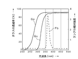
- FIG. 8 shows transmittance characteristics with respect to the light wavelength of each glass and radiation spectrum characteristics of the black lamp (10 [W]), which are evaluation data of Pyrex (registered trademark) glass, soda glass, and black lamp.
- Gp is the transmittance of Pyrex (registered trademark) glass
- Gs is the transmittance of soda glass
- Fb is the emission spectrum of the black lamp.
- Pyrex (registered trademark) glass ensures a transmittance of 85 to 95% at a light wavelength of 300 [nm] or more
- soda glass has a light wavelength of from 85 to 95 [%] at a wavelength of 350 [nm] or more. Ensure transmittance.
- the relative light intensity of the lamp exists in the light wavelength range of 350 to 400 [nm]. Therefore, even if inexpensive soda glass is used as the particles 3... And a black lamp is used as the light source (light emitting unit 5) of the ultraviolet irradiation light, the necessary and sufficient light guiding properties can be ensured.
- FIG. 9 shows the light intensity characteristics with respect to the light wavelength of the particles 3.
- Fi is a light intensity characteristic when a welding surface J is provided between the two particles 3 and 3.
- Fr is a light intensity characteristic when two independent particles 3 and 3 are simply brought into contact with each other.
- the light intensity characteristic is such that one end of the light incident side optical fiber is opposed to one end side in the arrangement direction of the two aligned grains 3 and 3, and one end of the light output side optical fiber is opposed to the other end side in the arrangement direction.
- the measurement was performed with the light from the light source incident on the other end of the light incident side optical fiber and the spectroscope on the other end of the light output side optical fiber. As shown in FIG.
- the above-described titanium dioxide is used for the photocatalyst layer 4
- known actions such as water purification, deodorization, sterilization, and antifouling are performed by the oxidation reaction and decomposition reaction by the photocatalyst. That is, as shown in FIG. 7, when the contaminant X is in contact with the surface of the photocatalyst layer 4 provided on the granule 3 (soda glass), the excitation light (ultraviolet light) U is simultaneously irradiated. In this way, the contaminant X is purified.
- the purifying action that satisfies this condition is significantly lower in the case of liquids than in the case of liquids, so that when the density is taken into consideration, a processing capacity that is 1000 times that of gas is actually required. Accordingly, increasing the substantial contact area where the contaminant X is brought into contact with the surface of the photocatalyst layer 4 and at the same time increasing the substantial irradiation area irradiated with the excitation light U increases the treatment capacity of the water purification device. It becomes an important factor in raising.
- Such a water purification device functions as follows. First, welding surfaces J are generated between the glass tube 2 and the particles 3 and between the particles 3, and a continuous light guide path C is provided via the welding surfaces J.
- the light is guided to each of the granules 3 through the light guide C, and is irradiated from the inner side of each of the granules 3 to the back surface of the photocatalyst layer 4 provided on the surface of each of the granules 3.
- the incident ultraviolet light is efficiently guided to most of the granules 3 in the glass tube 2 without greatly deteriorating the light intensity. Therefore, if the peripheral surface of the glass tube 2 in the photochemical reactor 1 can be irradiated with light from the external light emitting unit 5, a water purification device that functions efficiently and effectively can be obtained.
- dirty treated water La flows into the glass tube 2 from the inlet 2 a at one end and passes through the inside of the glass tube 2.
- the water La to be treated circulates in contact with the photocatalyst layer 4 provided on the surface of the large number of granules 3 existing inside the glass tube 2 and at the same time, the inner side of most of the granules 3. Since the photocatalyst layer 4 is irradiated with ultraviolet rays as excitation light from the photocatalyst layer 4 and the photocatalyst layer 4 is activated, dirt in water, such as various environmental hormones, dioxins, trihalomethanes, etc.
- FIG. 10 shows the photochemical reactor 1 in which the photocatalytic layer 4 is not provided. That is, the photochemical reactor 1 having the basic configuration obtained in step S9 in FIG. 1 is used as it is. Even in this case, since the welding surfaces J and the light guide C are formed, efficient light irradiation can be performed on the fluid flowing through the glass tube 2. Therefore, for example, by flowing an organic solvent in which margarine is dissolved in ethanol and activating the trans isomer of the margarine component, it can be used for applications such as changing to a cis isomer on the short wavelength side. After such treatment, if the ethanol is volatilized, the trans form considered harmful can be removed.
- FIG. 11 shows a case where polymer particles (resin particles) are used in place of the above-described first silica particles Bm ... when providing the porous surface Ef.
- the polymer particles (resin particles) are removed by using heating or the like at the time of sintering, it is possible to provide the porous surface Ef having a large number of micropores 7 shown in FIG.
- FIG. 12 shows a structure in which the particles 3 are provided with a coating layer 3c made of a transparent material having a melting point lower than that of the glass material on the surface of a base 3b formed of a single glass material.
- the granules 3 to be used can be manufactured in advance. That is, first, 58 [wt%] Na 2 SiO 3 (0.5 M) and 42 [wt%] HCI (1 M) are prepared as a material for producing a low melting point glass, and the precursor is prepared by sufficiently stirring. Prepare the solution. Next, the substrate 3b formed of a single glass material is dipped in the precursor solution, and then taken out and dried. Thereby, the granule 3 ... which has the coating layer 3c ...
- substrate 3b ... is obtained. Then, if the photochemical reactor 1 is manufactured using the particles 3..., Weld surfaces J... Formed by the coating layers 3 c. Even in this case, the above-described porous surface Ef can be provided similarly. In this way, if the particles 3... Having the coating layer 3 c... Provided on the surface of the substrate 3 b... Are used, the welded surface J can be generated by the coating layer 3 c. Thus, the photochemical reactor 1 is manufactured at a lower heating temperature. can do. In particular, since unnecessary dissolution of the base bodies 3b can be avoided, the shape of the base bodies 3b can be maintained as it is.
- the modified embodiment shown in FIGS. 13 and 14 is obtained by changing the size of the silica particles (first silica particles) Bm, in particular, with respect to the embodiments shown in FIGS. 1 to 6 described above, spherical particles (glass beads) having an outer diameter of 5 [mm] and silica particles Bm... Having an average diameter of approximately 9 [ ⁇ m] are used as the granules 3.
- spherical particles (glass beads) having an outer diameter of 5 [mm]
- silica particles Bm... Having an average diameter of approximately 9 [ ⁇ m] are used as the granules 3.
- a large number of silica particles Bm... Having a particle size of about 9 [ ⁇ m] adhere to the outer peripheral surface of the granule 3, and the outer peripheral surface of the granule 3 can be easily and well made porous.
- silica particles Bm are not usually deposited as a single layer structure on the outer peripheral surface of the granule 3, but other silica particles are further deposited on the silica particles Bm attached on the outer peripheral surface.
- the relative size of the flow path forming space 51 (see FIG. 13) formed between the particles 3 is considerably larger than the size of the silica particles Bm.
- the to-be-processed fluid La flowing near the center of the flow path forming space 51 is hardly processed.
- the embodiment shown in FIGS. 1 to 6, that is, the spherical body (glass beads) having an outer diameter of 5 [mm] and the silica particles Bm having an average diameter of about 9 [ ⁇ m] are used as the granular body 3.
- the embodiment is suitable for the treatment of the gas and the fluid to be treated La having a low viscosity, the embodiment is not necessarily suitable depending on the type of the fluid to be treated La such as the fluid to be treated La having a high viscosity.
- the spherical bodies (glass beads) having the same outer diameter 5 [mm] are used as the granules 3, but the particle diameter of the silica particles Bm... Is selected to 1 [mm].
- the effect of the difference in size of the silica particles Bm was verified.
- a large number of granules 3 having an outer diameter of 5 [mm] and a large number of silica particles Bm having a particle diameter of 1 [mm] are preliminarily set to 1 : Mixing at a ratio of 24 and heat-welding to produce a structure Q as shown in FIG. 13 and applying the surface forming agent E to the structure Q as in the case of FIG. The same process was performed.
- FIG. 13 shows only one structural unit of the structure Q extracted.
- the fluid La to be treated can be sufficiently brought into contact with the outer peripheral surface of the silica particles Bm, and the flow paths formed between the individual granules 3 for the silica particles Bm.
- the relative size of the formation space 51 can be reduced, and even the fluid L to be treated having a high viscosity can be sufficiently accommodated.
- the conversion rate characteristic Ps resulting from this measurement is shown by a solid line in FIG.
- a structure not using the silica particles Bm that is, a structure obtained by removing the silica particles Bm from the structure shown in FIG. 13 was similarly manufactured and subjected to the same measurement.
- the conversion rate characteristic Pr as a result of this measurement is shown in phantom in FIG.
- the conversion rate characteristic Ps is approximately twice as large as the conversion rate characteristic Pr, and the effectiveness of the effect was recognized.
- the particle diameter of the silica particles Bm is set in the range of 1 to 100 [ ⁇ m], but the modified embodiment of FIGS. In consideration of the fact that the outer diameter of the silica particles Bm can be arbitrarily selected, the particle diameter of the silica particles Bm... Considering this, it is possible to select from a range of 10% or less.
- any glass material other than those illustrated can be used, and the use of other transparent materials that exhibit the same action as the glass material is not excluded.
- the glass tube 2 was formed in the linear form (I form) was shown, you may bend
- the light source lamp it is possible to select a light source that emits a wavelength suitable for the photocatalyst or reactant used, and it does not exclude light sources other than the exemplified lamp.
- the photocatalyst layer 4 was formed using titanium dioxide was shown, the case where it forms using the substance which exhibits another photocatalytic action is not excluded.
- the photochemical reactor 1 according to the present invention can be widely used for various photochemical reactors capable of reacting a fluid (liquid, gas) with light or light components, and practically an exemplified water purification device. , Gas (air) purification equipment, drinking water purification equipment, high-concentration sewage treatment equipment, photochemical reactors, deodorizing equipment, sterilization equipment, etc. .
Landscapes
- Chemical & Material Sciences (AREA)
- Organic Chemistry (AREA)
- Chemical Kinetics & Catalysis (AREA)
- General Health & Medical Sciences (AREA)
- Toxicology (AREA)
- Physics & Mathematics (AREA)
- Health & Medical Sciences (AREA)
- Electromagnetism (AREA)
- Inorganic Chemistry (AREA)
- Catalysts (AREA)
- Engineering & Computer Science (AREA)
- Materials Engineering (AREA)
- Exhaust Gas Treatment By Means Of Catalyst (AREA)
- Silicon Compounds (AREA)
- Physical Or Chemical Processes And Apparatus (AREA)
Abstract
アルコキシシランを含有するシリカ分散液Agに、粒径が1〔μm〕以上となり、かつ粒径が粒体3の外径に対して15〔%〕以下となる範囲の大きさに選定した多数のシリカ粒子Bm…を添加し、ゾルゲル法を用いて表面形成剤Eを生成するとともに、この表面形成剤Eをガラス管2の内部面2f,3fに塗布した後、当該表面形成剤Eを所定の固着用温度により加熱処理し、シリカ粒子Bm…を、シリカ分散液Agの一部が残留する状態でガラス管2の内部面2f,3fに固着することにより多孔質面Efを設ける。
Description
本発明は、流体処理装置等を製造する際に用いて好適な多孔質面形成方法,光化学反応器の製造方法及び光化学反応器に関する。
従来、ガラス素材により形成した粒体の表面に二酸化チタンをコーティングして構成した光触媒体を、ガラス管等の容器に多数収容し、この光触媒体に光(紫外線)を照射するとともに、被処理水を通過させることにより、当該被処理水を浄化するようにした浄水装置(光反応器)は知られており、特許文献1には浄化装置が開示され、また、特許文献2には水処理装置が開示されている。
特許文献1に開示される浄化装置は、ガラス等のように紫外線を透過させる材料で形成された両端が開放された外管と、この外管に収容されて、外管との間に、ガラスビーズ表面にアナタース型二酸化チタンが被覆された光触媒が充填されると共に、被処理水が供給される処理空間を形成する内管と、外管の両端部に設けられたガラスフィルタと、外管の近傍に配置された紫外線を照射する紫外線ランプと、紫外線ランプから照射された紫外線を外管に向けて反射する反射板とを備えて構成したものであり、また、特許文献2に開示される水処理装置は、円筒形状容器である処理槽が、駆動装置の回転支軸上に取り付けられ、中心軸を軸にして、毎分1~5回転程度の速さで回転するよう設置され、その内部には、球状ガラスの担体にアナターゼ型結晶からなる二酸化チタンを主成分としたコーティングが施された無数の光触媒体を収容しており、さらにこの光触媒体に対して光を照射する棒状紫外線ランプが配置され、さらに、処理槽の一方に被処理水の導入パイプが、また、他方に、排出パイプが設けられ、この処理槽に所定の流通量となるよう被処理水が導入・排出されるように設定されたものである。
しかし、これら従来における浄水装置(浄化装置,水処理装置)は、次のような問題点があった。
即ち、いずれの浄水装置も、ガラス素材により形成した粒体の表面に二酸化チタンをコーティングして構成した光触媒体を多数用いることにより、被処理水に対する二酸化チタン(光触媒)の接触面積を増大させて処理能力(処理効率)を高めている。一方、光触媒に対しては紫外線を照射する必要があるため、特許文献1のように、ガラス管に多数の光触媒体を充填した場合には、多くの光触媒体は他の光触媒体の陰になる。したがって、陰になる光触媒体は活性化されなくなり、紫外線の照射面積を増大させる観点からは不十分となる。結局、処理能力(処理効率)を高めるには限界がある。
また、特許文献2は、処理槽を毎分1~5回転程度の速さで回転させるため、この処理槽に収容された光触媒体はランダムに撹拌される。したがって、全ての光触媒体を平均的に活性化できるものの陰になる光触媒体を活性化できない点は引用文献1の場合と同じであり、紫外線の照射面積を増大させる観点からは不十分となる。しかも、大型の処理槽やこの処理槽を回転させる駆動装置が必要となるなど、装置全体のコストアップ及び大型化を招くとともに、電力を使用する必要があることから、省エネルギ性に劣り、加えて、使用できる場所が限定されるなど、汎用性にも劣る。
そこで、本出願人は、既に特許文献3により、これらの問題を解決するための光反応器及びその製造方法を提案した。この光反応器及びその製造方法は、流体に対する粒体の表面の接触面積を増大させ、更に粒体の表面に対する照射面積を増大させることにより、流体に対する処理能力(処理効率)を高めるとともに、少ない部品点数で容易に製造可能にし、全体のコストダウン及び小型コンパクト化、更には省エネルギ性及び汎用性を高めることを目的としたものであり、具体的には、ガラス管の中にガラス素材により形成した多数の粒体を収容し、かつガラス管の中に流体を流通可能に構成した光反応器であって、ガラス管と粒体間の当接部,及び粒体同士間の当接部を、それぞれ所定の面積を有する溶着面とすることにより、ガラス管及び粒体に溶着面を介して連続する導光路を設けて光反応器を構成したものである。また、その製造方法は、ガラス管に粒体を充填した後、当該粒体を充填したガラス管を所定の加熱温度で加熱することにより、ガラス管と粒体間の当接部,及び粒体同士間の当接部に、それぞれ所定の面積を有する溶着面を生成し、ガラス管及び粒体に溶着面を介して連続する導光路を設けるようにしたものである。
しかし、上述した特許文献3で開示される光反応器及びその製造方法は、次のような解決すべき課題も残されていた。
第一に、流体に対する粒体表面の接触面積を増大させ、更に粒体表面に対する照射面積を増大させることができるため、流体に対する処理能力を高めるという一定の目的は達成できるものの、実用性の観点からは必ずしも十分であるとはいえない。例えば、3〔cm〕内径のガラス管に、5〔mm〕径に形成した多数の粒体を収容した場合、単なるガラス管に比べて内部表面積は概ね4.5倍に、また、クロロフェノールの光化学反応活性(分解反応)は概ね6.3倍に増大するが、実用性を確保する観点からは活性が不足しており、処理能力を高めるためには更なる改善の余地があった。
第二に、少ない部品点数で容易に製造可能にし、全体のコストダウン及び小型コンパクト化、更には省エネルギ性及び汎用性を高めるという一定の目的は達成できるものの、処理能力をより高めるには、流体に対する粒体表面の接触面積をより増大させる必要があることから、全体のサイズやコストが犠牲になりやすい。即ち、粒体表面の接触面積を増大させる場合、粒体の量を増やしたりガラス管を長くするなどの手段を講ずれば、接触面積の増大は可能になるが、全体の大型化及び流通性の低下を招きやすい。結局、処理能力を高めつつ、大型化を回避し、流通性を維持するのは容易でない。
本発明は、このような背景技術に存在する課題を解決した多孔質面形成方法,光化学反応器の製造方法及び光化学反応器の提供を目的とするものである。
上記課題を解決するため、本発明の多孔質面形成方法は、上述した課題を解決するため、被形成体Gの表面に多孔質面Efを設けるに際し、アルコキシシランを含有したシリカ分散液Agに、所定の粒径を有する多数のシリカ粒子Bm…を添加し、ゾルゲル法を用いて表面形成剤Eを生成するとともに、この表面形成剤Eを被形成体Gの表面に塗布した後、当該表面形成剤Eを所定の固着用温度により加熱処理し、シリカ粒子Bm…を、シリカ分散液Agの一部が残留する状態で被形成体Gの表面に固着することにより多孔質面Efを設けることを特徴とする。
この場合、発明の好適な態様により、シリカ分散液Agには、シリカ粒子(第一シリカ粒子)Bm…よりも小径となる1~300〔nm〕範囲内の粒径を有する多数の第二シリカ粒子Bs…を含ませることができる。
また、本発明に係る光化学反応器の製造方法は、上述した課題を解決するため、ガラス管2の内部に、ガラス素材により形成した多数の粒体3…を充填した後、当該粒体3…を充填したガラス管2を所定の溶融用温度で加熱処理することにより、ガラス管2と粒体3…間の当接部,及び粒体3…同士間の当接部に、それぞれ所定の面積を有する溶着面J…を生成し、ガラス管2及び粒体3…に溶着面J…を介して連続する導光路Cを設けてなる光化学反応器1を製造するに際し、アルコキシシランを含有したシリカ分散液Agに、粒径が1〔μm〕以上となり、かつ粒径が粒体3の外径に対して15〔%〕以下となる範囲の大きさに選定した多数のシリカ粒子Bm…を添加し、ゾルゲル法を用いて表面形成剤Eを生成するとともに、この表面形成剤Eを、ガラス管2の内部面2f…,3f…に塗布した後、当該表面形成剤Eを所定の固着用温度により加熱処理し、シリカ粒子Bm…を、シリカ分散液Agの一部が残留する状態でガラス管2の内部面2f…,3f…に固着することにより多孔質面Efを設けることを特徴とする。
この場合、発明の好適な態様により、シリカ分散液Agには、シリカ粒子(第一シリカ粒子)Bm…よりも小径となる1~300〔nm〕範囲内の粒径を有する多数の第二シリカ粒子Bs…を含ませることができる。また、多孔質面Efの表面には光触媒層4…を設けることができる。
さらに、本発明に係る光化学反応器1は、ガラス管2の内部に、ガラス素材により形成した多数の粒体3…を充填し、ガラス管2と粒体3…間の当接部,及び粒体3…同士間の当接部に、それぞれ所定の面積を有する溶着面J…を設けることにより、ガラス管2及び粒体3…に溶着面J…を介して連続する導光路Cを設けてなる光化学反応器であって、ガラス管2の内部面に、粒径が1〔μm〕以上となり、かつ粒径が粒体3の外径に対して15〔%〕以下となる範囲の大きさに選定した多数のシリカ粒子Bm…を固着することにより、多孔質面Efを設けてなることを特徴とする。
この場合、発明の好適な態様により、ガラス管2の一端が被処理流体Laの流入口2iとなり、かつ他端が処理流体Lbの流出口2eとなる流体処理装置Mに用いることができるとともに、ガラス管2の周面に対して外部の発光部5から光を照射可能にすることもできる。
このように構成する本発明に係る光化学反応器1は、ガラス管2の内部に形成される流通路に望む内部面2f,3f…に階層構造を導入し、マイクロメートルオーダーのメインチャンネルとナノメートルオーダーのサブチャンネルを設けることにより、実用的な流通量を確保しつつ内部表面積を増大させることができる。したがって、ガラス管2の周面に照射された光が内部面2f,3f…の多孔質階層にまで導光されたとき、光の強度はガラス管2の周面における強度と比較して1/1000程度まで低下することが考えられる。一般に、光化学反応では、励起状態の濃度が高まれば、励起状態間の相互作用による失活のため、光利用率(量子効率又は量子収率)が著しく低下する。一方、光強度を低下させれば、光化学反応器1の反応速度は低下するため、反応収量と量子効率はトレードオフの関係にある。本発明に係る光化学反応器1では、ガラス管2の周面から入る光は、ミリメートルオーダーのガラスからマイクロメートルオーダーのガラスに導かれるとともに、流通路を流れる流体(反応溶液)は、マイクロメートルオーダーからミリメートルオーダーの多孔質チャンネル(多孔質面Ef)を流通するため、物質移動速度が確保されつつ、広い活性表面が確保される。したがって、例えば、光化学反応器1における多孔質面Efの表面に光触媒層4…、即ち、ナノメートルオーダーの光触媒超微粒子を担持すれば、活性と処理速度を高めた光触媒反応器として利用可能となる。
このような本発明に係る多孔質面形成方法,光化学反応器の製造方法及び光化学反応器によれば、次のような顕著な効果を奏する。
(1) 多孔質面形成方法は、アルコキシシランを含有したシリカ分散液Agに、粒径が1〔μm〕以上となり、かつ粒径が粒体3の外径に対して15〔%〕以下となる多数のシリカ粒子Bm…を添加し、ゾルゲル法を用いて表面形成剤Eを生成するとともに、この表面形成剤Eを被形成体Gの表面に塗布した後、当該表面形成剤Eを所定の固着用温度により加熱処理し、シリカ粒子Bm…を、シリカ分散液Agの一部が残留する状態で被形成体Gの表面に固着することにより、多孔質面Efを設けるようにしたため、被形成体Gにおける表面の主要な幾何学的な変化をほとんど伴うことなく、当該表面の実質的な面積を飛躍的に増大させることができる。
(2) 光化学反応器の製造方法は、ガラス管2の内部に、ガラス素材により形成した多数の粒体3…を充填した後、当該粒体3…を充填したガラス管2を所定の溶融用温度で加熱処理することにより、ガラス管2と粒体3…間の当接部,及び粒体3…同士間の当接部に、それぞれ所定の面積を有する溶着面J…を生成し、ガラス管2及び粒体3…に溶着面J…を介して連続する導光路Cを設ける光化学反応器1を製造するに際して、被形成体Gとなるガラス管2と粒体3…に上述した多孔質面形成方法を利用できるため、ガラス管2の内部を流れる流体に対する接触面積を飛躍的に増大させることができる。したがって、ガラス管2の内部面2f,3f…に接する流体の光化学反応活性も、多孔質面Efを設けないガラス管2の内周面に比べて、実用的となる1000倍程度まで容易に増大させることができる。この結果、処理能力を大幅に高めた光化学反応器1を得ることができるとともに、ガラス管2の内部における流通路の断面積を大きく損なう不具合及び全体の大型化を招く不具合も回避できる。
(3) 好適な態様により、シリカ分散液Agに、シリカ粒子(第一シリカ粒子)Bm…よりも小径となる1~300〔nm〕範囲内の粒径を有する多数の第二シリカ粒子Bs…を含ませれば、第一シリカ粒子Bm…に対する固着機能(接合機能)をより高めることができるため、被形成体Gの表面、即ち、ガラス管2の内部面2f…,3f…に対して、第一シリカ粒子Bm…をより強固かつ安定に固着することができる。
(4) 好適な態様により、光化学反応器1における多孔質面Efの表面に、光触媒層4…を設ければ、ガラス管2の一端が被処理流体Laの流入口2iとなり、かつ他端が処理流体Lbの流出口2eとなる流体処理装置Mを容易に構築できるとともに、被処理流体Laを浄化する際における処理能力(処理効率)を飛躍的に高め、しかも、コストダウン及び小型コンパクト化を図ることができる流体処理装置Mとして提供できる。
(5) 好適な態様により、光化学反応器1におけるガラス管2の周面に対して外部の発光部5から光を照射可能にすれば、より効率的かつ効果的に機能する流体処理装置Mを容易に得ることができる。
1:光化学反応器,2:ガラス管,2i:流入口,2e:流出口,3…:粒体,3f…:粒体の表面,4…:光触媒層,5:発光部,G:被形成体,Ef:多孔質面,Bm…:シリカ粒子(第一シリカ粒子),Bs…:第二シリカ粒子,E:表面形成剤,Ag:シリカ分散液,J…:溶着面,C:導光路,La:被処理流体,Lb:処理流体,M:流体処理装置
次に、本発明に係る好適実施形態を挙げ、図面に基づき詳細に説明する。
まず、本実施形態に係る光化学反応器の製造方法について、図1(図2)に示すフローチャート、更には図3(a)~(e)及び図4を参照して説明する。
最初に、使用部品となるガラス管2及び多数の粒体3…を準備する(ステップS1)。このガラス管2及び多数の粒体3…は本発明における被形成体Gを構成する。ガラス管2は、図3(a)に示すように、断面形状が円形の単管であり、パイレックス(登録商標)ガラス等の耐熱ガラスを用いて形成する。したがって、所定の径を有する長いガラスパイプから使用する長さ分だけ切断することにより目的のガラス管2を容易に得ることができる。なお、ガラス管2の断面形状を円形に形成すれば、最もポピュラな形状にできるため、容易かつ低コストに製造できる利点がある。ガラス管2の内径,外径及び長さは、特に限定されるものではなく、例示のガラス管2は内径を30〔mm〕に選定した。
一方、粒体3は、ガラス素材を用いて同一径の球状に形成する。同一径となる球状の粒体3…を用いることにより、処理性能においてバラツキの少ない、品質及び均質性の高い光化学反応器1を得ることができる。粒体3のガラス素材には、上述したパイレックス(登録商標)ガラスをはじめ、汎用的なソーダガラスやシリカガラス等も用いることができる。なお、粒体3…は、同一径の球状に形成することが望ましいが、他の様々な形状に形成可能である。例示の粒体3には外径を5〔mm〕に選定した球体(ガラスビーズ)を用いた。
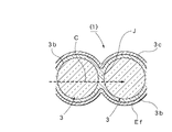
ガラス管2及び多数の粒体3…を準備したなら、図3(a)に示すように、基板治具21の上にガラス管2を起立させ、ガラス管2の上端開口から粒体3…を投入することによりガラス管2の内部に充填する(ステップS2)。次いで、図3(b)に示すように、ヒータ22により加熱を行う加熱炉23の内部に、粒体3…を充填したガラス管2を収容し、予め設定した加熱温度(溶融用温度)Th〔℃〕の温度環境下で予め設定した加熱時間Zhだけ加熱処理する(ステップS3,S4)。これにより、ガラス管2と粒体3…の表面は、加熱温度Th〔℃〕により溶解し、ガラス管2と粒体3…間の当接部,及び粒体3…同士間の当接部がそれぞれ溶着することにより、所定の面積を有する溶着面J…(図4(a)参照)が生成される。
この場合、加熱温度Th〔℃〕が低過ぎる場合には溶解不足が発生し、十分かつ良好な溶着面J…が得られない。また、加熱温度Th〔℃〕が高過ぎる場合には過度に溶解し、良好な内部形状が得られないとともに、流路も狭くなる。したがって、加熱温度Th〔℃〕及び加熱時間Zhは、実験等により最適値を設定することが望ましい。なお、例示の場合、加熱温度Th〔℃〕としては、600~700〔℃〕程度が良好である。そして、加熱時間Zhが経過したなら加熱炉23からガラス管2を取り出し、自然冷却により常温まで冷却する(ステップS5)。これにより、ガラス管2及び粒体3…には溶着面J…を介して連続する導光路Cが設けられる。
このように、ガラス管2に粒体3…を充填した後、当該粒体3…を充填したガラス管2を所定の加熱温度Thで加熱することにより、ガラス管2と粒体3…間の当接部,及び粒体3…同士間の当接部に、それぞれ所定の面積を有する溶着面J…を生成するようにすれば、少ない部品点数により極めて容易に製造することができ、全体のコストダウン及び小型コンパクト化を実現できるとともに、動力部等は不要なため、省エネルギ性及び汎用性にも優れる利点がある。
次いで、ガラス管2の内部面2f,3f…に、多孔質面Efを設けるための表面形成剤Eを塗布する。この場合、ガラス管2の内部面2f,3f…には、ガラス管2の内周面2fと粒体3…の表面3f…が含まれる。このため、使用する表面形成剤Eは、別途製造して予め用意する(ステップS20)。この表面形成剤Eの使用は、本発明の重要な技術的要素になるため、以下、この表面形成剤Eを得ることができる製造方法(実施例)について、図2に示すフローチャートを参照して具体的に説明する。
まず、主要原料としてシリカ分散水溶液Aoを用意する(ステップS21)。このシリカ分散水溶液Aoは、径がナノメートルオーダーの多数のシリカ粒子Bs…を含む水溶液であり、本実施例では径が100〔nm〕オーダーのシリカ粒子(第二シリカ粒子)Bs…を含む市販のシリカ分散水溶液Ao(4.8〔wt%〕)を用いた。このようなシリカ粒子Bs…を用いる理由は、非結晶性のシリカ粒子(石英)を使用することにより分光による発色を防止するためである。なお、第二シリカ粒子Bsの粒径は、1~300〔nm〕の範囲に選定することが望ましい。このように、シリカ分散水溶液Aoとして、後述する多孔質化に用いる第一シリカ粒子Bm…よりも十分に小径となる1~300〔nm〕範囲内の粒径を有する第二シリカ粒子Bs…を含む溶媒(溶液)を用いれば、第一シリカ粒子Bm…に対する固着機能(接合機能)をより高めることができるため、被形成体Gの表面、即ち、ガラス管2の内部面2f,3f…に対して、第一シリカ粒子Bm…をより強固かつ安定に固着できる利点がある。
次いで、用意したシリカ分散水溶液Aoに対して同量のメタノールを添加し、回転速度6000〔rpm〕,処理時間30〔分〕の条件下で遠心分離処理を行う(ステップS22,S23)。遠心分離処理が終了したなら、透明な上澄み液を除去し、除去後の残液量を半分にする(ステップS24)。さらに、上澄み液を除去した残液に対して同量のメタノールを添加し、振盪撹拌を行う(ステップS25,S26)。振盪撹拌が終了したなら、回転速度6000〔rpm〕,処理時間30〔分〕の条件下で遠心分離処理を行う(ステップS27)。遠心分離処理が終了したなら、透明な上澄み液を除去し、除去後の残液量を半分にする(ステップS28)。そして、以上のステップS25~S28の処理を設定回数(例示の場合、8回)だけ繰り返して行う(ステップS29)。これらの処理が終了したなら、得られたシリカ分散液の容量に対して、60〔%〕容量のメタノールを添加し、振盪撹拌を行うことにより、3〔wt%〕のゲル状のシリカ分散液Agを得る(ステップS30,S31,S32)。この際に得られるシリカ分散液Agの水分量は概ね0.4〔wt%〕となる。なお、アルコール溶媒にシリカ粒子(第二シリカ粒子Bs…)を分散させた同様の分散液を用いることも可能である。この場合には、上述したステップS22~S32の処理工程を省略することができる。
この後、シリカ分散液Agを計量し、所定量のテトラエトキシシラン(TEOS)を添加する(ステップS33,S34)。なお、TEOSは、シリカ前駆体、即ち、アルコキシシランの一例として例示するものであり、テトラメトキシシラン等のアルコキシシランに属する他のシリカ前駆体を用いることも可能である。したがって、前駆体として用いるアルコキシドを限定するものではない。また、これらのアルコキシドは、部分的に重合しておくことが接着強度(固着強度)を高める上で有効である。
そして、スターラーを用いて撹拌した後、径がマイクロメートルオーダーとなる多数のシリカ粒子(第一シリカ粒子)Bm…を所定量添加する(ステップS35,S36)。この場合、100〔ml〕当たりのシリカ分散液Agに対して、25〔g〕のTEOSを用いるとともに、2.5〔g〕の第一シリカ粒子Bm…を用いることが望ましい。この第一シリカ粒子Bm…は、粒体3…の表面3f…に固着して多孔質化するための材料となるため、その粒径は1~100〔μm〕の範囲に選定することが望ましい。本実施例では、平均径が概ね9〔μm〕となる第一シリカ粒子Bm…を用いた。そして、この後は、常温下で12時間にわたって撹拌を継続した(ステップS37,S38)。これにより、ゾルゲル法に基づく処理が行われ、ゲル化した適度の粘性を有する表面形成剤Eを得ることができる(ステップS39,S20)。
他方、得られた表面形成剤Eは、ガラス管2の内部面2f,3f…に塗布する。この場合、図3(c)に示すように、ガラス管2の上端開口から表面形成剤Eを注入し、ガラス管2の内部に表面形成剤Eを充填する(ステップS6)。この際、必要により振動等を加え、粒体3…同士間の隙間等に表面形成剤Eを浸透させることができる。一方、均等に浸透したなら、ガラス管2から表面形成剤Eを排出する(ステップS7)。これにより、粒体3…を含むガラス管2の内部面2f,3f…に表面形成剤Eが塗布される。このように、ゲル化した表面形成剤Eを利用することにより、混在する第一シリカ粒子Bm…を、ガラス管2の内部面2f,3f…であるガラス管2の内周面2f及び粒体3…の表面3f…に対して均一に付着させることができる。
この後、表面形成剤Eを塗布した粒体3…を含むガラス管2を、温度150〔℃〕,処理時間10〔分〕の条件下でアニール処理する(ステップS8)。アニール処理が終了したなら、図3(d)に示すように、ガラス管2をマッフル炉24に収容し、所定の加熱温度(固着用温度)として400〔℃〕,加熱時間として1時間の条件下で焼成を行う(ステップS9)。これにより、ガラス管2の内部面2f,3f…に多孔質面Efが設けられた基本構成の光化学反応器1を得ることができる。
得られた光化学反応器1は、図4(a),(b)に示すように、5〔mm〕径の粒体3…の表面3f…上に、9〔μm〕径となる多数の第一シリカ粒子Bm…が固着した状態となる。この際、図4(c),(d)に示すように、シリカ分散液Agの一部が残留する状態となり、このシリカ分散液Agの一部が、第一シリカ粒子Bm…同士及び第一シリカ粒子Bm…と粒体3…の表面3f…を固着するいわば接着剤(固着剤)として機能する。特に、図4(d)に示すように、シリカ分散液Agには、100〔nm〕径となる多数の第二シリカ粒子Bs…が含まれるため、いわば砂利を混ぜたコンクリートと同様の原理により、シリカ分散液Agはより強固な結合機能を発揮する。このため、焼成後は、シリカ分散液Agの一部が残留する状態となるように、固着用温度及び加熱時間等の処理条件を予め実験等に基づいて設定する。この場合、第一シリカ粒子Bm…及び第二シリカ粒子Bs…を含むシリカ分散液Agは、非結晶性を有する透明なガラス質となるため、ガラス素材により形成された透明な粒体3…の表面3f…に固着することにより、当該表面3f…は実質的な多孔質面Efとして形成される。なお、必要により、ステップS6~S9を繰り返すことにより、多孔質面Efにおける層厚を調整することも可能である。
他方、本実施例では、基本構成の光化学反応器1における多孔質面Efの表面上に、更に、アナターゼ型の二酸化チタンによる光触媒層4を設けた。この場合、ステップS9で得られた光化学反応器1に対して、上述した表面形成剤Eを塗布する場合と同様の方法により光触媒用溶液Kを塗布することができる。即ち、前述した図3(c)に示す工程と同様に、ガラス管2の上端開口から光触媒用溶液Kを注入し、ガラス管2の内部に光触媒用溶液Kを充填する(ステップS10)。なお、光触媒用溶液Kは、二酸化チタンを主成分とし、必要なバインダ等を含ませることができる。この際、必要により振動等を加え、第一シリカ粒子Bm…同士間の隙間等に光触媒用溶液Kを浸透させることができる。一方、所定の時間が経過したなら、ガラス管2から光触媒用溶液Kを排出する(ステップS11)。光触媒用溶液Kを排出したなら、排出後のガラス管2に対して乾燥処理又は焼成処理を行う(ステップS12)。そして、この後は、基板治具21を取り除き、ガラス管2の端面や外周面等に付着した不要な光触媒層4等を取り除くなどの仕上げを行うとともに、さらに、導光性等の検査を行えば、図3(e)に示す光化学反応機能を有する光化学反応器1を得ることができる(ステップS13)。
よって、このような本実施形態に係る光化学反応器の製造方法によれば、ガラス管2の内部に、ガラス素材により形成した多数の粒体3…を充填した後、当該粒体3…を充填したガラス管2を所定の溶融用温度で加熱処理することにより、ガラス管2と粒体3…間の当接部,及び粒体3…同士間の当接部に、それぞれ所定の面積を有する溶着面J…を生成し、ガラス管2及び粒体3…に溶着面J…を介して連続する導光路Cを設ける光化学反応器1を製造するに際して、アルコキシシランの一つであるTEOSを含有するシリカ分散液Agに、1~100〔μm〕範囲内の粒径を有する多数のシリカ粒子Bm…を添加し、ゾルゲル法を用いて表面形成剤Eを生成するとともに、この表面形成剤Eをガラス管2の内部面2f,3f…に塗布した後、当該表面形成剤Eを所定の固着用温度により加熱処理し、シリカ粒子Bm…を、シリカ分散液Agの一部が残留する状態で、ガラス管2の内部面2f,3f…に固着することにより多孔質面Efを設けるようにしたため、ガラス管2の内部を流れる流体に対する接触面積を飛躍的に増大させることができる。したがって、ガラス管2の内部面2f,3f…に接する流体の光化学反応活性も、多孔質面Efを設けないガラス管2の内周面に比べて、実用的となる1000倍程度まで容易に増大させることができる。この結果、処理能力を大幅に高めた光化学反応器1を得ることができるとともに、ガラス管2の内部における流通路の断面積を大きく損なう不具合及び全体の大型化を招く不具合も回避できる。
例示の場合、粒体3の表面3fに、第一シリカ粒子Bm…を10段により設けたとすれば、計算上、流れる流体に対する光化学反応活性は概ね数百倍となる。したがって、第一シリカ粒子Bmの粒径を4〔μm〕とし、25段により設けた場合には、計算上、光化学反応活性は1000倍となる。また、このような光化学反応活性は、光が弱いほど高くなるため、単位時間当たりに処理できる量を増やすことができる。本実施形態では、粒体3…の表面3f…に多孔質面Efを設けているため、光は分散して弱くなる。したがって、実際の光化学反応活性は上述した計算値よりも更に高くなるものと推測される。
ところで、本実施形態に係る多孔質面形成方法は、光化学反応器1の製造のみならず、いわば一般的なガラス体(石英基板,ソーダ硝子等を含む)の表面に多孔質面Efを設ける際にもそのまま適用可能である。即ち、この場合、アルコキシシランを含有するシリカ分散液Agに、1~100〔μm〕範囲内の粒径を有する多数のシリカ粒子Bm…を添加し、ゾルゲル法を用いて表面形成剤Eを生成するとともに、この表面形成剤Eをガラス体の表面に塗布した後、当該表面形成剤Eを所定の固着用温度により加熱処理し、シリカ粒子Bm…をシリカ分散液Agの一部が残留する状態でガラス体の表面に固着することにより当該ガラス体の表面に多孔質面Efを設けることができる。したがって、本実施形態に係る多孔質面形成方法は、ガラス体以外の被形成体G、具体的には、シリコンウェハやFTO基板等の酸化物系基体の表面に多孔質面Efを設ける際にも利用できる。特に、例示したシリカ粒子Bm…,Bs…を用いた場合、材質の観点から200-1000〔nm〕の広い波長領域における透明性が高くなるため、紫外光及び可視光に吸収帯を有する有機分子の光化学反応及び光触媒反応に適用可能である。
このように、被形成体Gが各種素材により形成され、或いは各種形状に形成される場合であっても容易に多孔質化することができるとともに、この場合であっても、被形成体Gにおける表面の主要な幾何学的な変化をほとんど伴うことなく、当該表面の実質的な面積を飛躍的に増大させることができる。特に、被形成体Gの表面が平坦面の場合には、スピンコート処理を行うことにより、より良好な結果を得ることができる。
次に、本実施形態に係る光化学反応器1の使用方法の一例について、図5~図9を参照して説明する。
基本構成による光化学反応器1は、図6に示すように、両端開口にキャップ31,32を装着して閉塞すれば、流体処理装置Mとして構成できる。各キャップ31,32の中央には、外方に突出する接続口31c,32cを有するため、各接続口31c,32cに配管33,34をそれぞれ接続すれば、光化学反応器1の内部に被処理流体Laを流入させることができるとともに、光化学反応器1の内部から処理流体Lbを流出させることができる。したがって、ガラス管2の一端が被処理流体Laの流入口2aとなり、かつ他端が処理流体Lbの流出口2bとなる流体処理装置Mが得られる。
なお、光化学反応器1に流通させる流体Lは、液体であってもよいし気体であってもよい。流体処理装置Mに、液体を適用すれば、例えば、水浄化装置等として利用できる。一方、気体を適用すれば、例えば、適切な触媒を担持した光化学反応器1を構成し、400~500〔℃〕に加熱するとともに、大気と水蒸気を通過させることにより二酸化炭素と水を反応させ、空気中の二酸化炭素を除去する空気浄化装置等として利用できる。したがって、このような空気浄化装置を、鉄工所や火力発電所等に付設すれば、二酸化炭素の排出削減手段として利用可能となる。
一方、本実施形態に係る光化学反応器1は、前述したように、基本構成に対して、さらに、溶着面J…を除く粒体3…の表面3f及びガラス管2の内周面2fに、アナターゼ型の二酸化チタンを用いた光触媒層4を設けている。したがって、上述した水浄化装置として用いることができる。即ち、光化学反応器1における多孔質面Efの表面に光触媒層4…を有するため、ガラス管2の一端が被処理流体(被処理水)Laの流入口2iとなり、かつ他端が処理流体(処理水)Lbの流出口2eとなる。
このように、光化学反応器1における多孔質面Efの表面に、光触媒層4…を設ければ、ガラス管2の一端が被処理流体Laの流入口2iとなり、かつ他端が処理流体Lbの流出口2eとなる水浄化装置等の流体処理装置Mを容易に構築できるとともに、被処理流体Laを浄化する際における処理能力(処理効率)を飛躍的に高め、しかも、コストダウン及び小型コンパクト化を図ることができる流体処理装置Mとして提供できる利点がある。また、光化学反応器1におけるガラス管2の周面に対して外部の発光部5から光を照射可能にすれば、より効率的かつ効果的に機能する水浄化装置等の流体処理装置Mを容易に得ることができる。
以下、水浄化装置として用いる場合について具体的に説明する。まず、図5に示すように、光触媒層4における光触媒を活性化させる紫外線照射光の光源となる発光部5をガラス管2の外周面に対面させて配設する。したがって、この発光部5には、紫外線を発光するブラックランプを用いることができる。これにより、発光部5から発光する紫外線はガラス管2の周面に照射される。なお、図5は、便宜上、一つの発光部5を示すが、光化学反応器1の回りに複数の発光部5…を配置したり、或いは断面半円形の反射板を、ガラス管2の周面に対向する位置であって発光部5に対して反対側の位置に配置するなどの構成を採用できる。
図8には、パイレックス(登録商標)ガラス,ソーダガラス及びブラックランプの評価データとなる、各ガラスの光波長に対する透過率特性及びブラックランプ(10〔W〕)の放射スペクトル特性を示す。図8中、Gpはパイレックス(登録商標)ガラスの透過率、Gsはソーダガラスの透過率、Fbはブラックランプの放射スペクトルである。パイレックス(登録商標)ガラスは、光波長が300〔nm〕以上で85~95〔%〕の透過率を確保し、ソーダガラスは、光波長が350〔nm〕以上で85~95〔%〕の透過率を確保する。また、ランプの相対光強度は、光波長が350~400〔nm〕の間に存在する。したがって、粒体3…として廉価なソーダガラスを使用するとともに、紫外線照射光の光源(発光部5)としてブラックランプを使用した場合であっても、必要十分な導光性を確保できる。
図9は、粒体3…同士の光波長に対する光強度特性を示す。図9中、Fiは、二つの粒体3と3間に溶着面Jを設けた場合の光強度特性である。なお、Frは、二つの独立した粒体3と3を単に接触させた場合の光強度特性である。光強度特性は、二つの並んだ粒体3,3の並び方向の一端側に入光側光ファイバの一端を対向させ、かつ並び方向の他端側に出光側光ファイバの一端を対向させるとともに、入光側光ファイバの他端に発光源の光を入光させ、かつ出光側光ファイバの他端に分光器を臨ませて測定した。図9に示すように、独立した粒体3と3を単に接触させたのみでは、いずれの波長域であってもほとんど光は透過しない。しかし、粒体3と3間に溶着面Jを生成することにより、少なくとも光波長が350〔nm〕以上において、十分な光の透過性(導光性)を確認できる。
このように、ガラス管2にパイレックス(登録商標)ガラス等の耐熱ガラスを使用し、粒体3…にソーダガラスを使用すれば、結果的に、ガラス管2の素材は、粒体3…の素材よりも融点が高くなる。したがって、粒体3…の表面に溶着面J…を直接生成する場合であっても、ガラス管2の無用な変形を招くなどの悪影響を回避することができる。また、単一のガラス素材により形成した粒体3…同士を溶着するため、粒体3…の表面に溶着面J…を直接生成でき、損失の少ない導光路Cを容易に設けることができる。さらに、ガラス管2には、外周面に対して外部の発光部5から光を照射可能な単管を用いるため、よりシンプルで廉価な水浄化装置(光化学反応器1)を構築可能である。
一方、光触媒層4には前述した二酸化チタンを用いるため、光触媒による酸化反応及び分解反応により、公知の作用である浄水,脱臭、除菌、防汚等の作用が行われる。即ち、図7に示すように、粒体3(ソーダガラス)に設けた光触媒層4の表面に汚染物質Xが接触している場合、同時に励起光(紫外線)Uが照射されていることを条件にして汚染物質Xの浄化が行われる。特に、この条件を満たす浄化作用は、液体の場合、気体に比べて著しく低くなるため、密度を考慮した場合、実際には、気体に比べて1000倍の処理能力が必要とされる。したがって、光触媒層4の表面に汚染物質Xを接触さる実質的な接触面積を増大させると同時に、励起光Uが照射される実質的な照射面積を増大させることは、水浄化装置の処理能力を高める上で重要な要素となる。
このような水浄化装置は(光化学反応器1)は次のように機能する。まず、ガラス管2と粒体3…間,及び粒体3…同士間には、それぞれ溶着面J…が生成され、この溶着面J…を介して連続する導光路Cを設けられているため、外部の発光部5からガラス管2の外周面に照射された光(紫外線)は、ガラス管2の外周面から内部に入光するとともに、入光した紫外線は、図5に点線矢印で示す導光路Cを通って、各粒体3…に導光され、各粒体3…の内部側から各粒体3…の表面に設けた光触媒層4の裏面に照射される。この際、入光した紫外線は、ガラス管2内のほとんどの粒体3…対して光強度が大きく劣化することなく効率的に導かれる。したがって、光化学反応器1におけるガラス管2の周面に対して外部の発光部5から光を照射可能にすれば、効率的かつ効果的に機能する水浄化装置を得ることができる。
他方、ガラス管2には、図6に示すように、一端の流入口2aから、例えば、汚れた被処理水Laが流入し、ガラス管2の内部を通過する。この際、被処理水Laは、ガラス管2の内部に存在する多数の粒体3…の表面に設けた光触媒層4に接触して流通するとともに、同時に、ほとんどの粒体3…において内部側から紫外線が励起光として光触媒層4に照射され、光触媒層4の活性化が行われているため、光触媒層4による酸化反応及び分解反応により、水中の汚れ、例えば、各種環境ホルモン,ダイオキシン,トリハロメタン,細菌類等の有害溶解物が、効率的に分解され、無害化される。そして、処理された後の処理水Lbは、他端の流出口2bから、直接又は図示を省略したストレーナを通して流出する。
次に、本発明の変更実施形態に係る各種光化学反応器1…について、図10~図14を参照して説明する。
図10は、光触媒層4を設けない光化学反応器1を示す。即ち、図1のステップS9で得られる基本構成の光化学反応器1をそのまま使用するものである。この場合であっても、溶着面J…及び導光路Cは形成されるため、ガラス管2を流通する流体に対して効率的な光照射が可能になる。したがって、例えば、エタノールにマーガリンを溶かした有機溶媒を流し、マーガリン成分のトランス体を活性化させることにより、短波長側にあるシス体に変化させるなどの用途に利用することが可能であり、このような処理後、エタノールを揮発させれば、有害とされるトランス体を除去することができる。
図11は、多孔質面Efを設けるに際し、前述した第一シリカ粒子Bm…の代わりに、ポリマ粒子(樹脂製粒子)を用いたものである。これにより、焼結時における加熱等を利用してポリマ粒子(樹脂製粒子)を除去すれば、図11に示す多数の微細孔7…有する多孔質面Efを設けることができる。
図12は、粒体3…を、単一のガラス素材により形成した基体3b…の表面に、当該ガラス素材よりも融点の低い透明素材によるコーティング層3c…を設けて構成したものである。この場合、使用する粒体3は予め製造することができる。即ち、最初に、低融点ガラスの生成材料として58〔重量%〕のNa2SiO3(0.5M)と42〔重量%〕のHCI(1M)を調合し、十分に撹拌することにより前駆体溶液を用意する。次いで、単一のガラス素材により形成した基体3b…を前駆体溶液に浸漬し、この後、取り出して乾燥する。これにより、基体3b…の表面にコーティング層3c…を有する粒体3…が得られる。そして、この粒体3…を使用して光化学反応器1を製造すれば、図12に示すように、コーティング層3c…同士による溶着面J…が生成される。また、この場合であっても前述した多孔質面Efを同様に設けることができる。このように、基体3b…の表面にコーティング層3c…を設けた粒体3…を用いれば、コーティング層3c…により溶着面J…を生成できるため、より低い加熱温度により光化学反応器1を製造することができる。特に、基体3b…の無用な溶解を回避できるため、基体3b…の形状をそのまま維持させることができる。
他方、図13及び図14に示す変更実施形態は、図1~図6に示した実施形態に対して、特に、シリカ粒子(第一シリカ粒子)Bmの大きさを変更したものである。前述した図1~図6の実施形態では、粒体3として外径5〔mm〕の球体(ガラスビーズ)及び平均径が概ね9〔μm〕となるシリカ粒子Bm…を用いた。これにより、粒体3の外周面には粒径9〔μm〕程度となる多数のシリカ粒子Bm…が付着し、粒体3における外周面の多孔質化が容易かつ良好に実現される。
ところで、この場合、多数のシリカ粒子Bm…は、通常、粒体3の外周面上に一層構造として付着するものではなく、外周面上に付着したシリカ粒子Bm…の上に更に他のシリカ粒子Bm…が何段にも付着する多層構造となる。したがって、図6に例示した光化学反応器1に被処理流体Laを供給した場合、当該被処理流体Laの粘度が高いなど、被処理流体Laの種類によっては、多層構造の内部に進入しにくくなり、各シリカ粒子Bm…の表面に対して十分に接触させることができない。加えて、シリカ粒子Bmの大きさに対して、各粒体3…間に形成される流路形成空間51(図13参照)の相対的大きさは、かなり大きくなる。結局、各シリカ粒子Bm…における光触媒層4自身は光により有効に活性化されるにしても、特に、流路形成空間51の中央付近を流通する被処理流体Laはほとんど処理されないことになる。このように、図1~図6に示した実施形態、即ち、粒体3として外径5〔mm〕の球体(ガラスビーズ)及び平均径が概ね9〔μm〕となるシリカ粒子Bm…を用いる実施形態は、気体及び粘度の低い被処理流体Laの処理には適するとしても、粘度が高い被処理流体Laなど、被処理流体Laの種類によっては必ずしも適した実施形態とはならない。
そこで、図13に示す変更実施形態では、粒体3は同一となる外径5〔mm〕の球体(ガラスビーズ)を用いるも、シリカ粒子Bm…の粒径を1〔mm〕に選定することによりシリカ粒子Bm…の大きさの相違による作用を検証した。なお、図13は当該検証を試みることを目的とするため、予め、外径5〔mm〕となる多数の粒体3…と粒径1〔mm〕となる多数のシリカ粒子Bm…を、1:24個の割合で混在させ、加熱溶着することにより、図13のような構造体Qを生成するとともに、この構造体Qに、前述した表面形成剤Eを塗布するなど、図6の場合と同様の処理を行った。なお、図13は構造体Qの一構成単位のみを抽出して示す。
したがって、この構造体Qの場合、粒体3の外径Dm(=5〔mm〕)に対するシリカ粒子Bmの外径Ds(=1〔mm〕)は20〔%〕となり、図1~図6に示した実施形態の場合と比べ、シリカ粒子Bmの外周面に対して、被処理流体Laを十分に接触させることができるとともに、シリカ粒子Bmに対する各粒体3…間に形成される流路形成空間51の相対的大きさは逆に小さくすることができ、粘度の高い被処理流体Lであっても十分に対応させることができる。
そして、この構造体Qにより、図5及び図6に示した光化学反応器1を同様に製作するとともに、光源として10〔W〕のブラックランプを使用し、光照射時間〔min〕に対する転化率〔%〕特性を測定した。この測定結果となる転化率特性Psを図14に実線で示す。なお、対照区として、シリカ粒子Bm…を用いない構造体、即ち、図13で示す構造体からシリカ粒子Bm…を除いた構造体も同様に製作し、同様の測定を行った。この測定結果となる転化率特性Prを図14に仮想線で示す。図14から明らかなように、転化率特性Psは、転化率特性Prに対して、概ね2倍程度大きくなり、効果の有為性が認められた。
よって、以上の結果から、シリカ粒子Bm…の粒径の大きさを選定するに際しては、各粒体3…により形成される流路形成空間51に進入できる大きさであれば足りるとともに、具体的な大きさの選定においては、被処理流体Laの性質や用途等を考慮すればよく、これにより、実用域としての光化学反応器1等の構築が可能になる。即ち、図1~図6の実施形態では、シリカ粒子Bm…の粒径を1~100〔μm〕の範囲としたが、図13及び図14の変更実施形態を考慮し、また、粒体3の外径も任意に選定できることを考慮すれば、シリカ粒子Bm…の粒径は、1〔μm〕以上となり、かつ粒体3の外径に対して15〔%〕以下、望ましくは溶着度合を考慮して10〔%〕以下となる範囲から選定可能となる。
以上、好適実施形態(変更実施形態)について詳細に説明したが、本発明は、このような実施形態に限定されるものではなく、細部の構成,形状,素材,数量,数値等において、本発明の精神を逸脱しない範囲で、任意に変更,追加,削除することができる。
例えば、ガラス管2の素材及び粒体3…の素材は、例示以外の任意のガラス素材を利用可能であるとともに、ガラス素材と同様の作用を呈する他の透明素材の使用を排除するものではない。また、ガラス管2は直線形(I形)に形成した場合を示したが、必要によりL形やU形等ように折曲したり湾曲させて形成してもよい。一方、光源ランプについても、使用する光触媒や反応物質に好適な波長を放射する光源を選択することが可能であり、例示したランプ以外の光源を排除するものではない。さらに、光触媒層4は二酸化チタンを用いて形成した場合を示したが、他の光触媒作用を呈する物質を用いて形成する場合を排除するものではない。
本発明に係る光化学反応器1は、広くは、光又は光の成分により流体(液体,気体)を反応させることができる各種光化学反応器に利用できるとともに、実用的には、例示の水浄化装置をはじめ、気体(空気)浄化装置,飲料水浄化装置,高濃度汚水処理装置,光化学反応器,消臭装置,滅菌装置,等の光化学反応器1を一部に備える各種装置及び機器に利用できる。
Claims (8)
- 被形成体の表面に多孔質面を設ける多孔質面形成方法であって、アルコキシシランを含有するシリカ分散液に、所定の粒径を有する多数のシリカ粒子を添加し、ゾルゲル法を用いて表面形成剤を生成するとともに、この表面形成剤を前記被形成体の表面に塗布した後、当該表面形成剤を所定の固着用温度により加熱処理し、前記シリカ粒子を前記シリカ分散液の一部が残留する状態で前記被形成体の表面に固着することにより多孔質面を設けることを特徴とする多孔質面形成方法。
- 前記シリカ分散液は、前記シリカ粒子(第一シリカ粒子)よりも小径となる1~300〔nm〕範囲内の粒径を有する多数の第二シリカ粒子を含むことを特徴とする請求項1記載の多孔質面形成方法。
- ガラス管の内部に、ガラス素材により形成した多数の粒体を充填した後、当該粒体を充填したガラス管を所定の溶融用温度で加熱処理することにより、前記ガラス管と前記粒体間の当接部,及び前記粒体同士間の当接部に、それぞれ所定の面積を有する溶着面を生成し、前記ガラス管及び前記粒体に前記溶着面を介して連続する導光路を設けてなる光化学反応器の製造方法であって、アルコキシシランを含有するシリカ分散液に、粒径が1〔μm〕以上となり、かつ粒径が前記粒体の外径に対して15〔%〕以下となる範囲の大きさに選定した多数のシリカ粒子を添加し、ゾルゲル法を用いて表面形成剤を生成するとともに、この表面形成剤を前記ガラス管の内部面に塗布した後、当該表面形成剤を所定の固着用温度により加熱処理し、前記シリカ粒子を、前記シリカ分散液の一部が残留する状態で前記ガラス管の内部面に固着することにより多孔質面を設けることを特徴とする光化学反応器の製造方法。
- 前記シリカ分散液は、前記シリカ粒子(第一シリカ粒子)よりも小径となる1~300〔nm〕範囲内の粒径を有する多数の第二シリカ粒子を含むことを特徴とする請求項3記載の光化学反応器の製造方法。
- 前記多孔質面の表面には光触媒層を設けることを特徴とする請求項3又は4記載の光化学反応器の製造方法。
- 前記ガラス管の内部に、ガラス素材により形成した多数の粒体を充填し、前記ガラス管と前記粒体間の当接部,及び前記粒体同士間の当接部に、それぞれ所定の面積を有する溶着面を設けることにより、前記ガラス管及び前記粒体に前記溶着面を介して連続する導光路を設けてなる光化学反応器であって、前記ガラス管の内部面に、粒径が1〔μm〕以上となり、かつ粒径が前記粒体の外径に対して15〔%〕以下となる範囲の大きさに選定した多数のシリカ粒子を固着することにより、多孔質面を設けてなることを特徴とする光化学反応器。
- 前記ガラス管の一端が被処理流体の流入口となり、かつ他端が処理流体の流出口となる流体処理装置に用いることを特徴とする請求項6記載の光化学反応器。
- 前記ガラス管の周面に対して、外部の発光部から光を照射可能にすることを特徴とする請求項6又は7記載の光化学反応器。
Applications Claiming Priority (2)
| Application Number | Priority Date | Filing Date | Title |
|---|---|---|---|
| JP2013-055936 | 2013-03-19 | ||
| JP2013055936A JP2016104675A (ja) | 2013-03-19 | 2013-03-19 | 多孔質面形成方法,光化学反応器の製造方法及び光化学反応器 |
Publications (1)
| Publication Number | Publication Date |
|---|---|
| WO2014148347A1 true WO2014148347A1 (ja) | 2014-09-25 |
Family
ID=51580033
Family Applications (1)
| Application Number | Title | Priority Date | Filing Date |
|---|---|---|---|
| PCT/JP2014/056652 Ceased WO2014148347A1 (ja) | 2013-03-19 | 2014-03-13 | 多孔質面形成方法,光化学反応器の製造方法及び光化学反応器 |
Country Status (2)
| Country | Link |
|---|---|
| JP (1) | JP2016104675A (ja) |
| WO (1) | WO2014148347A1 (ja) |
Families Citing this family (1)
| Publication number | Priority date | Publication date | Assignee | Title |
|---|---|---|---|---|
| JP2023054701A (ja) * | 2021-10-04 | 2023-04-14 | 日鉄ケミカル&マテリアル株式会社 | 円筒型光触媒セル |
Citations (4)
| Publication number | Priority date | Publication date | Assignee | Title |
|---|---|---|---|---|
| JPH11319578A (ja) * | 1998-05-15 | 1999-11-24 | Matsushita Electric Ind Co Ltd | 透明膜および透明膜の製造方法 |
| JP2006306708A (ja) * | 2005-03-29 | 2006-11-09 | Catalysts & Chem Ind Co Ltd | チタニウム含有シリカゾル、その製造方法およびその用途 |
| JP2012025163A (ja) * | 2011-09-07 | 2012-02-09 | Nippon Soda Co Ltd | 光触媒担持構造体 |
| WO2012017637A1 (ja) * | 2010-08-03 | 2012-02-09 | 国立大学法人信州大学 | 光反応器及びその製造方法 |
-
2013
- 2013-03-19 JP JP2013055936A patent/JP2016104675A/ja active Pending
-
2014
- 2014-03-13 WO PCT/JP2014/056652 patent/WO2014148347A1/ja not_active Ceased
Patent Citations (4)
| Publication number | Priority date | Publication date | Assignee | Title |
|---|---|---|---|---|
| JPH11319578A (ja) * | 1998-05-15 | 1999-11-24 | Matsushita Electric Ind Co Ltd | 透明膜および透明膜の製造方法 |
| JP2006306708A (ja) * | 2005-03-29 | 2006-11-09 | Catalysts & Chem Ind Co Ltd | チタニウム含有シリカゾル、その製造方法およびその用途 |
| WO2012017637A1 (ja) * | 2010-08-03 | 2012-02-09 | 国立大学法人信州大学 | 光反応器及びその製造方法 |
| JP2012025163A (ja) * | 2011-09-07 | 2012-02-09 | Nippon Soda Co Ltd | 光触媒担持構造体 |
Also Published As
| Publication number | Publication date |
|---|---|
| JP2016104675A (ja) | 2016-06-09 |
Similar Documents
| Publication | Publication Date | Title |
|---|---|---|
| CN103052441B (zh) | 光反应器及其制造方法 | |
| Blount et al. | Transparent thin-film TiO2 photocatalysts with high activity | |
| Stone et al. | Synthesis, characterization, and photocatalytic activity of titania and niobia mesoporous molecular sieves | |
| Puma et al. | Preparation of titanium dioxide photocatalyst loaded onto activated carbon support using chemical vapor deposition: A review paper | |
| WO1997031703A1 (en) | Glass material for carrying a photocatalyst, filter device using the same and light irradiating method | |
| CN101301606B (zh) | 一种掺杂型纳米二氧化钛光催化剂的制备方法 | |
| CN102658115B (zh) | 用于空气净化的掺铈纳米二氧化钛/活性炭纤维复合光催化剂及其制备方法 | |
| Kowalska et al. | Photoreactors for wastewater treatment: A review | |
| Bechec et al. | Gas‐Phase Photooxidation: Reactors and Materials | |
| JP2009249268A (ja) | 金属酸化物内包メソポーラスシリカカプセル | |
| KR20170026966A (ko) | 광촉매 비드, 이를 구비하는 광촉매 필터 및 광촉매 필터의 제조 방법 | |
| CN106470757A (zh) | 流体流通器和光化学反应器 | |
| EP3912702A1 (en) | Glass or aluminum structure air filter using photocatalyst precoat and manufacturing method therefor | |
| Gao et al. | Engineered inverse opal structured semiconductors for solar light-driven environmental catalysis | |
| Plantard et al. | Kinetic and efficiency of TiO2-coated on foam or tissue and TiO2-suspension in a photocatalytic reactor applied to the degradation of the 2, 4-dichlorophenol | |
| CN106693946A (zh) | 一种石墨烯/氧化钛复合可见光催化剂的制备方法 | |
| WO2014148347A1 (ja) | 多孔質面形成方法,光化学反応器の製造方法及び光化学反応器 | |
| Szołdra et al. | Photocatalytic degradation of nitrogen oxides (NOx) in a continuous-flow photoreactor with aluminosilicate microspheres coated with TiO2 thin films. | |
| CN109908966A (zh) | 光催化复合材料及其制备方法 | |
| WO1997037936A1 (en) | A photocatalytic reactor for water purification and use thereof | |
| EP3528940B1 (en) | GAS-PHASE PHOTOCATALYTIC REACTOR FOR FAST AND EFFICIENT DEGRADATION OF POLLUTANTS | |
| CN102408246A (zh) | 一种氮掺杂硅铝固载TiO2多孔陶瓷的制备方法 | |
| CN109675590B (zh) | 一种二氧化钛的制备方法 | |
| CN208561761U (zh) | 一种光催化污水处理装置 | |
| RU2477257C1 (ru) | Композиция на основе нанокристаллического диоксида титана, способ ее изготовления и способ применения композиции для получения фотокаталитического покрытия на стекле |
Legal Events
| Date | Code | Title | Description |
|---|---|---|---|
| 121 | Ep: the epo has been informed by wipo that ep was designated in this application |
Ref document number: 14767677 Country of ref document: EP Kind code of ref document: A1 |
|
| DPE1 | Request for preliminary examination filed after expiration of 19th month from priority date (pct application filed from 20040101) | ||
| NENP | Non-entry into the national phase |
Ref country code: DE |
|
| 122 | Ep: pct application non-entry in european phase |
Ref document number: 14767677 Country of ref document: EP Kind code of ref document: A1 |
|
| NENP | Non-entry into the national phase |
Ref country code: JP |