WO2014148272A1 - 電子棚札システム - Google Patents
電子棚札システム Download PDFInfo
- Publication number
- WO2014148272A1 WO2014148272A1 PCT/JP2014/055840 JP2014055840W WO2014148272A1 WO 2014148272 A1 WO2014148272 A1 WO 2014148272A1 JP 2014055840 W JP2014055840 W JP 2014055840W WO 2014148272 A1 WO2014148272 A1 WO 2014148272A1
- Authority
- WO
- WIPO (PCT)
- Prior art keywords
- electronic shelf
- shelf label
- unit
- server
- control unit
- Prior art date
- Legal status (The legal status is an assumption and is not a legal conclusion. Google has not performed a legal analysis and makes no representation as to the accuracy of the status listed.)
- Ceased
Links
Images

Classifications
-
- A—HUMAN NECESSITIES
- A47—FURNITURE; DOMESTIC ARTICLES OR APPLIANCES; COFFEE MILLS; SPICE MILLS; SUCTION CLEANERS IN GENERAL
- A47F—SPECIAL FURNITURE, FITTINGS, OR ACCESSORIES FOR SHOPS, STOREHOUSES, BARS, RESTAURANTS OR THE LIKE; PAYING COUNTERS
- A47F5/00—Show stands, hangers, or shelves characterised by their constructional features
- A47F5/0043—Show shelves
- A47F5/0068—Shelf extensions, e.g. fixed on price rail
-
- G—PHYSICS
- G06—COMPUTING OR CALCULATING; COUNTING
- G06F—ELECTRIC DIGITAL DATA PROCESSING
- G06F3/00—Input arrangements for transferring data to be processed into a form capable of being handled by the computer; Output arrangements for transferring data from processing unit to output unit, e.g. interface arrangements
- G06F3/14—Digital output to display device ; Cooperation and interconnection of the display device with other functional units
- G06F3/147—Digital output to display device ; Cooperation and interconnection of the display device with other functional units using display panels
-
- G—PHYSICS
- G07—CHECKING-DEVICES
- G07G—REGISTERING THE RECEIPT OF CASH, VALUABLES, OR TOKENS
- G07G1/00—Cash registers
- G07G1/12—Cash registers electronically operated
- G07G1/14—Systems including one or more distant stations co-operating with a central processing unit
- G07G1/145—PLU-management
-
- G—PHYSICS
- G09—EDUCATION; CRYPTOGRAPHY; DISPLAY; ADVERTISING; SEALS
- G09G—ARRANGEMENTS OR CIRCUITS FOR CONTROL OF INDICATING DEVICES USING STATIC MEANS TO PRESENT VARIABLE INFORMATION
- G09G2330/00—Aspects of power supply; Aspects of display protection and defect management
- G09G2330/02—Details of power systems and of start or stop of display operation
- G09G2330/021—Power management, e.g. power saving
-
- G—PHYSICS
- G09—EDUCATION; CRYPTOGRAPHY; DISPLAY; ADVERTISING; SEALS
- G09G—ARRANGEMENTS OR CIRCUITS FOR CONTROL OF INDICATING DEVICES USING STATIC MEANS TO PRESENT VARIABLE INFORMATION
- G09G2370/00—Aspects of data communication
- G09G2370/16—Use of wireless transmission of display information
-
- G—PHYSICS
- G09—EDUCATION; CRYPTOGRAPHY; DISPLAY; ADVERTISING; SEALS
- G09G—ARRANGEMENTS OR CIRCUITS FOR CONTROL OF INDICATING DEVICES USING STATIC MEANS TO PRESENT VARIABLE INFORMATION
- G09G2380/00—Specific applications
- G09G2380/04—Electronic labels
Definitions
- the present invention relates to a radio wave type electronic shelf label system that exchanges information with a server via radio waves.
- radio wave electronic shelf label systems have been employed (for example, Patent Document 1 (Japanese Patent Laid-Open No. 2001-148074)).
- product information is transmitted by radio waves from a server that manages product information to electronic shelf labels installed at sales floors, etc., and the display contents of the electronic shelf label change based on the received product information Is done.
- an operator such as an employee of a store displays a display of a specific electronic shelf label on a normal screen (display for a customer) at a sales floor where the electronic shelf label is installed. It may be necessary to switch from a screen) to a management screen (display screen used by an operator for product management) or to change information stored in a specific electronic shelf label. In such a case, an operator may operate the electronic shelf label at the sales floor where the electronic shelf label is installed using a portable radio remote controller.
- radio waves are generally low in directivity, and other electronic shelf labels that are not subject to operation may be erroneously operated.
- electronic shelf labels are often arranged close to each other at store sales floors, and such erroneous operations are likely to occur.
- An object of the present invention is to provide an electronic shelf label system in which a server and an electronic shelf label communicate with each other by radio waves, so that an operator can operate the electronic shelf label at a place where the electronic shelf label is installed without operating it erroneously.
- An object of the present invention is to provide an electronic shelf label system capable of operating only the target electronic shelf label.
- the electronic shelf label system includes a plurality of electronic shelf labels, a server, a radio wave transmitter, and a portable transmitter.
- the electronic shelf label is arranged corresponding to each of the plurality of products, and displays product information regarding the corresponding product.
- the server stores product information.
- the radio wave transmitter transmits product information stored in the server by radio waves toward a plurality of electronic shelf labels.
- the portable transmitter transmits individual commands for individual electronic shelf labels by short-range wireless communication.
- the electronic shelf label includes a first receiving unit, a second receiving unit, and a processing unit.
- the first receiving unit receives product information transmitted from the radio wave transmitter.
- the second receiving unit receives an individual command transmitted from the portable transmitter.
- the processing unit executes processing according to the individual command.
- the electronic shelf label can receive an individual command transmitted from a portable transmitter by near field communication (NFC). Therefore, it is easy for an operator to operate only the electronic shelf label to be operated without erroneously operating the electronic shelf label other than the operation target at a sales floor where the electronic shelf label is installed.
- NFC near field communication
- the second receiving unit has a memory for storing individual commands. It is desirable that the second receiving unit writes an individual command in the memory using power supplied from the portable transmitter to the second receiving unit by non-contact power transmission.
- the electronic shelf label further includes a battery that supplies power to the processing unit. It is desirable that the second receiving unit further includes a unit control unit that controls the operation of the second receiving unit. It is desirable that the unit controller does not receive power from the battery.
- the unit controller of the second receiving unit does not use the battery power. Therefore, compared with the case where a unit control part performs confirmation of the presence or absence of signal transmission from a portable transmitter using the electric power of a battery, the exchange frequency of the battery of an electronic shelf label can be controlled. As a result, the cost of battery replacement (the cost of the battery itself and the labor cost for battery replacement) can be suppressed.
- the electronic shelf label further includes a battery that supplies power to the processing unit.
- the second receiving unit preferably has a signal transmission unit that transmits a signal to the processing unit. It is desirable for the processing unit to have, as operation modes, a standby mode that minimizes power consumption and a startup mode that consumes more power than the standby mode.
- the signal transmission unit preferably transmits a signal for switching the operation mode to the activation mode to the processing unit in the standby mode.
- the operation mode of the processing unit is switched to the start mode after the second receiving unit receives the individual command. Therefore, the processing unit does not consume battery power because it waits for the input of an individual command from a portable transmitter that does not know when it will be transmitted. As a result, the battery replacement frequency of the electronic shelf label can be suppressed, and the battery replacement cost can be suppressed.
- the second receiving unit is supplied with power from the portable transmitter by non-contact power transmission. It is desirable that the signal transmission unit transmits a signal to the processing unit using the power supplied from the portable transmitter.
- the signal transmission unit of the second receiving unit does not consume battery power for signal transmission to the processing unit, the frequency of replacement of the battery of the electronic shelf label can be suppressed, and the cost of battery replacement can be suppressed. it can.
- the communicable distance between the second receiving unit and the portable transmitter is 10 cm or less.
- the electronic shelf label can receive an individual command transmitted from the portable transmitter by short-range wireless communication. Therefore, it is easy for an operator to operate only the electronic shelf label to be operated without erroneously operating the electronic shelf label other than the operation target at a sales floor where the electronic shelf label is installed.
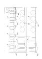
- FIG. 1 It is a figure which shows the electronic shelf label system which concerns on one Embodiment of this invention. It is a figure which shows the example of arrangement
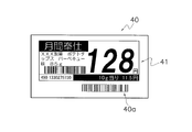
- FIG. 1 It is a figure which shows the external appearance of the electronic shelf label with which the electronic shelf label system which concerns on FIG. 1 is provided.
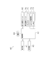
- FIG. 1 It is a block diagram which shows schematic structure of the electronic shelf label with which the electronic shelf label system which concerns on FIG. 1 is provided.
- a configuration connected by a solid line indicates that the components are electrically connected.
- a configuration connected to the control unit by a broken line indicates that driving power is supplied from the battery.
- the electronic shelf label system 1 according to the present embodiment is merely an example of the embodiment of the present invention, and the electronic shelf label system according to the present invention is not limited to the contents described below. Other modes can be adopted as long as they do not contradict the gist of the invention.
- the electronic shelf label system 1 is used in stores such as supermarkets and convenience stores.
- the electronic shelf label system 1 mainly includes a plurality of electronic shelf labels 40, 40,..., An electronic shelf label server 10, and a plurality of access points 30, 30,.
- a remote controller 50 and a handy terminal 80 are included.
- the numbers of electronic shelf labels 40, access points 30, remote controllers 50, and handy terminals 80 included in the electronic shelf label system 1 are not limited to the numbers shown in FIG.
- the electronic shelf label 40 is a portable device and is a display device arranged corresponding to each of a plurality of products P handled in the store.
- the electronic shelf label 40 is arranged in the vicinity of the corresponding product P among the plurality of types of products P displayed on the store floor of the store, and displays product information regarding the corresponding product P (see FIG. 2).
- the merchandise information is various information related to the merchandise P, and includes, for example, a normal sale price, a special sale price, a discount rate, a sales quantity, an inventory quantity, etc. of the merchandise P.
- the electronic shelf label server 10 is a computer that comprehensively controls the electronic shelf label system 1.
- the functions of the electronic shelf label server 10 include management of product information displayed on the electronic shelf label 40.
- the product information is stored in the server storage unit 14 of the electronic shelf label server 10 as will be described later.
- the electronic shelf label server 10 transmits distribution data including product information to the electronic shelf label 40 via the access point 30.
- the electronic shelf label server 10 transmits the product information to the electronic shelf label 40 as image data (image data displayed on the display unit 41 of the electronic shelf label 40 described later). It is not limited to.
- the electronic shelf label server 10 may transmit product information such as a normal selling price as numerical data to the electronic shelf label 40.
- the access point 30 is a radio wave transmitter / receiver.
- the access point 30 exchanges various signals with the electronic shelf label 40 using radio waves.
- the access points 30 are attached to a ceiling in a store, for example, with a certain interval.
- the installation location, installation interval, and the like of the access point 30 are determined so that the electronic shelf label 40 installed in the store can communicate with any access point 30.
- the access point 30 is connected to the electronic shelf label server 10 via a network 2 such as a LAN (Local Area Network).
- a network 2 such as a LAN (Local Area Network).
- the access point 30 transmits distribution data (distribution data including product information) transmitted from the electronic shelf label server 10 to the access point 30 via the network 2 to the plurality of electronic shelf labels 40 by radio waves. That is, the access point 30 is an example of a radio wave transmitter. Further, the access point 30 receives a signal transmitted from the electronic shelf label 40 and transmits the received signal to the electronic shelf label server 10 via the network 2.
- the remote controller 50 is a portable transceiver.
- the remote controller 50 exchanges various signals with each electronic shelf label 40 using near field communication (NFC).
- NFC near field communication
- the short-range wireless communication here means communication at a distance of several centimeters to several tens of centimeters.
- the remote controller 50 transmits an individual command for the individual electronic shelf label 40 by short-range wireless communication using an electromagnetic field. That is, the remote controller 50 is an example of a portable transmitter.
- the handy terminal 80 is configured to be able to read identification information such as a barcode attached to the electronic shelf label 40 or the product P, and is a portable information terminal mainly used for information collection. .
- the handy terminal 80 is mainly used for linking the device ID of the electronic shelf label 40 and the product ID of the product P. The link work will be described later.
- the electronic shelf label 40 is arranged corresponding to each of the plurality of products P handled in the store, and displays product information regarding the corresponding product P (see FIG. 2). ). For example, on the electronic shelf label 40, the product name, the unit price per weight, and the sales price of the product P are displayed as product information (see FIG. 3).
- the electronic shelf label 40 mainly includes a display unit 41, a control unit 42, a storage unit 43, a battery 44, a first communication unit 60, and a second communication unit 70.
- the display unit 41 is a screen for displaying product information stored in the storage unit 43 described later (see FIG. 3).
- Electronic paper is used for the display unit 41. That is, the display unit 41 is a dot matrix non-volatile display unit including a plurality of pixels arranged in a matrix.
- the display unit 41 can hold the display content even when power is not supplied.
- the display unit 41 is not limited to electronic paper, and for example, a liquid crystal display may be used.
- the screen displayed on the display unit 41 includes a normal screen and a management screen.
- the normal screen is a screen for customers, and the display unit 41 displays, for example, the product name, the unit price per weight, and the sales price of the product P as product information (see FIG. 3).
- the management screen is a screen used by a store clerk or the like for product management, and the display unit 41 displays, for example, the number of sales, the number of orders, and the number of inventory of the product P as product information.
- the operator operates the electronic shelf label 40 with the remote controller 50 at the site where the electronic shelf label 40 is installed (by transmitting an individual command from the remote controller 50 to the second communication unit 70).
- the display of the unit 41 can be switched from the normal screen to the management screen.
- the control unit 42 is an example of a processing unit.
- the control unit 42 is mainly configured by a CPU.
- the control part 42 is electrically connected to the display part 41, the memory
- the control unit 42 receives supply of driving power from the battery 44 (see the broken line in FIG. 4).
- the control unit 42 controls each unit of the electronic shelf label 40 by executing a program stored in the storage unit 43 described later.
- the control unit 42 controls the display unit 41 such that product information (image data) received from the electronic shelf label server 10 by the first communication unit 60 described later is displayed on the display unit 41.
- the control unit 42 controls the operations of the display unit 41, the storage unit 43, and the first communication unit 60 in order to execute processing according to an individual command received by the second communication unit 70 described later.
- the individual command is a command transmitted to the individual electronic shelf label 40 from the remote controller 50 described later.
- the individual command includes, for example, a command for switching the display on the display unit 41 from the normal screen to the management screen.
- the individual command includes a command for controlling the first communication unit 60 so that the distribution data transmitted from the access point 30 can be received.
- the control unit 42 has a sleep mode (standby mode) and a wake-up mode (startup mode) as operation modes.
- the sleep mode is a mode in which the power consumption of the electronic shelf label 40 is minimized (consumption of the battery 44 is minimized).
- the control unit 42 controls the display unit 41, the storage unit 43, the first communication unit 60, and the memory 73 of the second communication unit 70 so that power is not supplied from the battery 44. Therefore, in the sleep mode, it is impossible to update the display of the display unit 41, switch the display of the display unit 41 from the normal screen to the management screen, or receive the radio wave by the first communication unit 60.
- the control unit 42 controls the battery 44 to supply power to the display unit 41, the storage unit 43, the first communication unit 60, and the memory 73 as necessary. For this reason, the power consumption of the electronic shelf label 40 in the wake-up mode is larger than the power consumption of the electronic shelf label 40 in the sleep mode.
- the operation mode of the controller 42 is long in the sleep mode in order to suppress the consumption of the battery 44 (the ratio of the time in which the operation mode is the sleep mode is high). Then, when one of the following two conditions is satisfied, the operation mode of the control unit 42 is switched from the sleep mode to the wake-up mode.
- the first condition is that a predetermined standby time elapses after the operation mode is switched to the sleep mode.
- the first condition is that the control unit 42 having a timer function determines that a predetermined standby time has elapsed since the operation mode was switched to the sleep mode.
- the waiting time is, for example, 1 minute, but is not limited to this. However, if the control unit 42 frequently shifts to the wake-up mode, the battery 44 is likely to be exhausted, so that the reaction time for transmission of product information from the electronic shelf label server 10 is acceptable for the user of the electronic shelf label system 1. It is desirable that the waiting time is as long as possible.
- the reaction time for the transmission of product information from the electronic shelf label server 10 means the time from when the electronic shelf label server 10 transmits the product information until the content is reflected on the display of the display unit 41. To do.
- the radio wave receiving unit of the electronic shelf label In order for the electronic shelf label to receive the radio waves of the remote controller, the radio wave receiving unit of the electronic shelf label must be pre- To be up). In other words, when a radio remote control is used, in order for the electronic shelf label to receive the remote control radio, the operation mode of the control unit of the electronic shelf label needs to be switched to the wake-up mode in advance. .
- the waiting time of the worker becomes long and the work efficiency is poor. Therefore, the waiting time needs to be set to a short time (for example, 1 second). There is.
- the operation mode of the control unit 42 is switched from the sleep mode to the wake-up mode. Then, the control unit 42 controls the first communication unit 60 to be supplied with driving power from the battery 44, and controls the first communication unit 60 to be able to receive distribution data transmitted from the access point 30. To do.
- the control unit 42 determines whether the received distribution data is distribution data transmitted to itself (transmitted to the electronic shelf label 40). Determine whether or not.
- the control unit 42 When it is determined that the received distribution data is distribution data transmitted to itself, the control unit 42 continues to execute necessary processing. Specifically, for example, the control unit 42 causes the first communication unit 60 to transmit a signal (ACK signal) indicating that the distribution data transmitted to itself is received to the access point 30. Control. Further, for example, the control unit 42 writes the product information (image data) included in the distribution data transmitted to itself into the storage unit 43 (performs an update process of the product information stored in the storage unit 43). . For example, the control unit 42 controls the display unit 41 so that the display content of the display unit 41 is changed to the product information written in the storage unit 43. When the necessary processing is completed, the operation mode of the control unit 42 is switched to the sleep mode.
- the control unit 42 When it is determined that the received distribution data is not distribution data transmitted to itself, or when the first communication unit 60 does not receive the distribution data within a predetermined time, the control unit 42 The operation mode is switched to the sleep mode.
- the control unit 42 determines whether or not the distribution data received by the first communication unit 60 has been transmitted to itself as follows.
- the distribution data transmitted from the electronic shelf label server 10 via the access point 30 includes product information and an identifier.
- the identifier is a device ID (a unique ID assigned to each electronic shelf label 40) of the electronic shelf label 40 that is the transmission target of the product information.
- the control unit 42 compares the identifier included in the signal received by the first communication unit 60 with its own device ID stored in the storage unit 43 which will be described later. It is determined that the distribution data is transmitted.
- the second condition (second condition) in which the operation mode of the control unit 42 is switched from the sleep mode to the wake-up mode is to control an interrupt signal transmitted by the unit control unit 72 of the second communication unit 70 described later.
- the part 42 is receiving.
- the operation mode of the control unit 42 is switched from the sleep mode to the wake-up mode.
- the control unit 42 reads out an individual command stored in a memory 73 of the second communication unit 70 described later, and executes a process according to the individual command.
- the storage unit 43 is a storage unit configured by a nonvolatile memory such as an EEPROM.
- a volatile memory such as a RAM may be used for the storage unit 43.
- the storage unit 43 is preferably a non-volatile memory.
- the storage unit 43 in addition to a program for the control unit 42 to control each part of the electronic shelf label 40, a device ID that is a unique identifier of the electronic shelf label 40, and a product transmitted from the electronic shelf label server 10 Information (image data) is stored.
- the product information includes product information for the normal screen and product information for the management screen.
- the battery 44 supplies driving power to the display unit 41 of the electronic shelf label 40, the control unit 42, the storage unit 43, the first communication unit 60, and the memory 73 of the second communication unit 70 described later. Supply (see broken line in FIG. 4).
- the second communication unit 70 uses the power supplied from the remote controller 50, the second communication unit 70 does not receive power from the battery 44 except for the memory 73.
- the unit controller 72 and the antenna 71 of the second communication unit 70 to be described later are not supplied with power from the battery 44.
- a memory 73 of the second communication unit 70 to be described later can receive power supply from both the battery 44 and the remote controller 50.
- the display unit 41, the storage unit 43, the first communication unit 60, and the memory 73 of the second communication unit 70 are provided with switches (not shown) such as FETs.
- the control unit 42 controls the power supply to the display unit 41, the storage unit 43, the first communication unit 60, and the memory 73 by controlling these switches.
- control unit 42 turns off the above-described switch to turn off the display unit 41 and the storage unit 43. Control is performed so that power is not supplied from the battery 44 to the first communication unit 60 and the memory 73.
- the first communication unit 60 is an example of a first receiving unit.
- the first communication unit 60 receives distribution data (including distribution data for which another electronic shelf label 40 is to be transmitted) transmitted by radio waves from the access point 30. Further, when the first communication unit 60 receives the distribution data transmitted to itself (the distribution data received by the first communication unit 60 is controlled to be distribution data transmitted to itself).
- the unit 42 determines), according to the instruction of the control unit 42, a signal (ACK signal) indicating that the distribution data transmitted to itself is received is transmitted to the access point 30 by radio waves.
- the second communication unit 70 receives an individual command transmitted from the remote controller 50.
- the second communication unit 70 is an example of a second receiving unit.
- the second communication unit 70 is a passive RF tag. That is, the second communication unit 70 is an RF tag that receives power supply from the remote controller 50 by non-contact power transmission. The second communication unit 70 does not receive power supply from the battery 44 except for the memory 73 described later.
- the second communication unit 70 is an electromagnetic induction type RF tag, but is not limited to this, and for example, a radio wave type RF tag may be used. As shown in FIG. 4, the second communication unit 70 mainly includes an antenna 71, a unit control unit 72, and a memory 73.
- the antenna 71 is a loop antenna (coil antenna) used for electromagnetic wave transmission / reception.
- the communicable distance between the second communication unit 70 and the remote controller 50 is 10 cm or less here.
- the communicable distance is not limited to this, but when the electronic shelf labels 40 are arranged close to each other (for example, two electronic shelf labels 40 depicted on the upper right in FIG. 2) It is desirable that the communicable distance be 10 cm or less so that the remote controller 50 does not mistakenly operate the electronic shelf label 40 that is not a communication target.
- the unit control unit 72 is an RF communication chip that controls the second communication unit 70 in response to an individual command from the remote controller 50.
- the unit controller 72 executes various processes using the power supplied from the remote controller 50 to the second communication unit 70 by non-contact power transmission.
- the unit controller 72 when the unit controller 72 receives an individual command from the remote controller 50 via the antenna 71, the unit controller 72 receives the received individual command using the power supplied from the remote controller 50 to the second communication unit 70 by non-contact power transmission. Is written in the memory 73.
- the unit controller 72 uses the power supplied from the remote controller 50 to the second communication unit 70 by non-contact power transmission.
- An interrupt signal is transmitted to 42. That is, the unit control unit 72 is an example of a signal transmission unit.
- the interrupt signal is a signal for notifying the control unit 42 that the second communication unit 70 has received the individual command from the remote controller 50.
- the control unit 42 reads out the individual command (the individual command transmitted from the remote controller 50) stored in the memory 73. Thereafter, the control unit 42 executes processing according to the individual command read from the memory 73.
- control unit 42 When the control unit 42 is in the sleep mode and the control unit 42 receives an interrupt signal from the unit control unit 72, the operation mode of the control unit 42 is first switched to the wake-up mode, and then the control The unit 42 reads the individual command and executes the read individual command.
- the unit control unit 72 reads out the information stored in the memory 73 and sends the read information to the remote controller 50. Send to.
- the memory 73 is configured by a nonvolatile memory such as an EEPROM.
- the memory 73 can receive power supply from both the battery 44 and the remote controller 50.
- the memory 73 In the memory 73, an individual command received from the remote controller 50 by the unit controller 72 via the antenna 71 is written.
- the memory 73 stores, for example, the device ID of the electronic shelf label.
- the device ID stored in the memory 73 is the same information as the device ID stored in the storage unit 43.
- the electronic shelf label server 10 is a computer that comprehensively manages the electronic shelf label system 1.
- the electronic shelf label server 10 transmits various commands and various information to the electronic shelf label 40 via the access point 30.
- the information transmitted from the electronic shelf label server 10 to the electronic shelf label 40 includes product information.
- the electronic shelf label server 10 is disposed in a store backyard or the like.
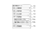
- the electronic shelf label server 10 includes a server communication unit 11, a server display unit 12, a server input unit 13, a server storage unit 14, and a server control unit 15 as main functional units (see FIG. 5).
- the server communication unit 11 is a communication interface for enabling communication between the electronic shelf label server 10, the access point 30, the handy terminal 80, and the like.
- the server communication unit 11 is also configured to be able to communicate with devices outside the electronic shelf label system 1 (for example, a POS system server and store controller installed in the store together with the electronic shelf label system 1).
- the distribution data sent from the server communication unit 11 to the access point 30 is further transmitted by radio waves from the access point 30 to the electronic shelf label 40.
- the server display unit 12 is a liquid crystal display. Various information related to the electronic shelf label system 1 can be displayed on the server display unit 12.
- the server input unit 13 is a mouse and a keyboard. A user of the electronic shelf label system 1 can input various commands and various information to the electronic shelf label server 10 via the server input unit 13.
- the server storage unit 14 includes a ROM, a RAM, a hard disk, and the like.
- the server storage unit 14 stores various programs executed by the server control unit 15 described later.
- Various information is stored in the server storage unit 14.
- the information stored in the server storage unit 14 includes a product master table 14a and an electronic shelf label master table 14b (see FIG. 5).
- the product master table 14a stores information (product information) related to products handled by the electronic shelf label system 1.
- the product information is various information about the product P. For example, the product name, price (normal sales price, special sales price), unit price (normal sales price / special sales price), discount rate, sales volume, inventory of the product P Including quantity.
- product information is stored for each product ID (barcode information of the product P).
- the contents of the merchandise master table 14a are obtained when the server communication unit 11 receives information from an external device (for example, a POS system (not shown) installed in the store) or the server input unit 13 accepts input of information. It is updated with.
- an external device for example, a POS system (not shown) installed in the store
- the server input unit 13 accepts input of information. It is updated with.
- the link work is carried out as follows.
- the worker displays a device ID of the electronic shelf label 40 (the same device ID stored in the storage unit 43 and the memory 73 of the electronic shelf label 40) attached to one electronic shelf label 40.
- the code 40a (see FIG. 3) is scanned by the reader of the handy terminal 80.
- the worker scans the barcode attached to the product P on which the electronic shelf label 40 displays the product information with the reader of the handy terminal 80.
- the scanned device ID and product ID are transmitted to the electronic shelf label server 10 via a communication line (not shown) (for example, a wireless LAN).
- the server control unit 15 to be described later links the transmitted device ID of the electronic shelf label 40 and the product ID of the product P, and stores them in the electronic shelf label master table 14b.
- the server control unit 15 performs various controls based on programs and various information stored in the server storage unit 14.
- the server control unit 15 stores the information in the electronic shelf label master.
- the table 14b is linked and stored.
- the server control unit 15 transmits product information to the electronic shelf label 40 via the access point 30 when the electronic shelf label system 1 is activated or when the display change of the electronic shelf label 40 is necessary.
- the display change of the electronic shelf label 40 for example, when the contents of the product master table 14a are updated, or when the price is changed from the normal selling price to the special selling price during the sale period of the product P, At the end of the special sale period for the product P, the price is changed from the special sale price to the normal sale price.
- the server control unit 15 performs the following processing when transmitting the product information to the electronic shelf label 40.
- the server control unit 15 refers to the product master table 14a, and generates product information (image data) to be transmitted to the electronic shelf label 40 for the product P that requires the display change of the electronic shelf label 40. Further, the server control unit 15 refers to the electronic shelf label master table 14b, and acquires, as an identifier, the device ID of the electronic shelf label 40 that is linked to the product P that requires the display change of the electronic shelf label 40. .
- the server control unit 15 generates distribution data including the generated screen information and the acquired identifier (device ID of the electronic shelf label 40 to be transmitted).
- the distribution data is data obtained by combining a header including an identifier and product information.
- the server control unit 15 transmits the generated distribution data to the access point 30.
- the access point 30 that has received the distribution data transmits the distribution data to the electronic shelf label 40 by radio waves.
- the access point 30 waits until the first communication unit 60 of the electronic shelf label 40 enters the wake-up mode, and then transmits the distribution data.
- the electronic shelf label 40 when receiving the distribution data for itself, transmits an ACK signal to the access point 30 by radio waves.
- the access point 30 that has received the ACK signal from the electronic shelf label 40 transmits the ACK signal to the server communication unit 11 of the electronic shelf label server 10 via the network 2.
- the server control unit 15 determines that the communication with the electronic shelf label 40 is successful, and ends the transmission process of the product information for the electronic shelf label 40.
- the server control unit 15 retransmits the distribution data. To do.
- the remote controller 50 is an RF tag reader / writer that reads and writes information of the second communication unit 70 of the electronic shelf label 40. As described above, the remote controller 50 exchanges various signals with each second communication unit 70 using near field communication (NFC). The remote controller 50 and the second communication unit 70 communicate using an electromagnetic field.
- NFC near field communication
- the worker or the like causes the electronic shelf label 40 to execute various processes by transmitting individual commands to the second communication unit 70 using the remote controller 50.
- the individual command includes a command for switching the display on the display unit 41 of the electronic shelf label 40 from the normal screen to the management screen, or from the management screen to the normal screen. Further, for example, in the individual command, the electronic shelf label 40 is caused to transmit a signal requesting the update of the product information to the electronic shelf label server 10 (via the access point 30). Includes instructions for receiving the latest product information.
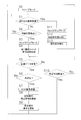
- FIG. 6 is a flowchart for explaining the operation of the control unit 42 of the electronic shelf label 40.
- the control unit 42 operates when the operation mode of the control unit 42 of the electronic shelf label 40 is in the sleep mode (in the state of step S0 in FIG. 6) will be described.
- step S ⁇ b> 1 the control unit 42 determines whether an interrupt signal has been received from the unit control unit 72 of the second communication unit 70. If an interrupt signal is received, the process proceeds to step S11. If no interrupt signal is received, the process proceeds to step S2.
- step S2 the control unit 42 determines whether or not a predetermined standby time has elapsed after the operation mode is switched to the sleep mode. If it is determined that the standby time has elapsed, the process proceeds to step S3. If it is determined that the standby time has not elapsed, the process returns to step S1.
- step S3 the operation mode of the control unit 42 is switched to the wake-up mode. Thereafter, the process proceeds to step S4.
- step S4 the control unit 42 controls the first communication unit 60 to be supplied with driving power from the battery 44, and controls the first communication unit 60 to be able to receive radio waves from the access point 30. .
- step S5 the control unit 42 determines whether or not the first communication unit 60 has received the distribution data transmitted by the access point 30. If it is determined that the distribution data has been received, the process proceeds to step S6. If it is determined that the distribution data has not been received, the process proceeds to step S10.
- step S ⁇ b> 6 the control unit 42 compares the identifier of the distribution data received by the first communication unit 60 with its own device ID stored in the storage unit 43, thereby receiving the first communication unit 60. It is determined whether or not the distribution data is distribution data addressed to itself. Specifically, if the identifier of the distribution data received by the first communication unit 60 matches the own device ID stored in the storage unit 43, the control unit 42 determines that the distribution data is addressed to itself. If they do not match, it is determined that the distribution data is not addressed to itself.
- step S7 the control unit 42 switches the operation mode to the sleep mode (returns to step S0).
- step S7 the control unit 42 controls the first communication unit 60 to transmit an ACK signal to the access point 30. Thereafter, the process proceeds to step S8.
- step S8 the control unit 42 stores the product information included in the distribution data received by the first communication unit 60 in the storage unit 43 (updates the product information stored in the storage unit 43).
- step S9 the control unit 42 causes the display unit 41 to display the updated product information (image data).
- the display unit 41 normally displays a normal screen (when the second communication unit 70 has not received an individual command for switching the display of the display unit 41 from the normal screen to the management screen). . Therefore, when only the product information (image data) related to the management screen is updated in step S8, step S9 may not be performed.
- step S9 ends, the control unit 42 switches the operation mode to the sleep mode (returns to step S0).
- step S10 when it is determined in step S5 that the distribution data has not been received, the control unit 42 controls the first communication unit 60 so that the distribution data can be received. (That is, after performing step S4), it is determined whether or not a predetermined time has elapsed. If it is determined in step S10 that the predetermined time has not elapsed, the process returns to step S5. On the other hand, when it is determined in step S10 that the predetermined time has elapsed, the control unit 42 switches the operation mode to the sleep mode (returns to step S0).
- step S1 when it is determined in step S1 that the control unit 42 has received the interrupt signal, the operation mode of the control unit 42 is switched to the wake-up mode in step S11. Thereafter, the process proceeds to step S12.
- step S12 the control unit 42 reads the individual command from the memory 73 of the second communication unit 70. Thereafter, the process proceeds to step S13.
- step S13 the control unit 42 performs a process according to the individual command read in step S12.
- the control unit 42 reads the product information (image data) for the management screen from the storage unit 43 and displays it.
- the unit 41 controls to display the read product information.
- the control unit 42 switches the operation mode to the sleep mode (returns to step S0).
- step S13 is not limited to the above contents.
- the control unit 42 may further switch the operation mode to the sleep mode after further executing a process of switching the management screen to the normal screen.
- the control unit 42 causes the first communication unit 60 to transmit a signal requesting the update of the product information to the electronic shelf label server 10 according to the individual command, and further causes the first communication unit 60 to The latest product information may be received from the electronic shelf label server 10.
- the link work is a work for associating (linking) the electronic shelf labels 40 with the products P for which the respective electronic shelf labels 40 display product information. Specifically, this is an operation for associating the device ID of the electronic shelf label 40 with the product ID of the product P for which each electronic shelf label 40 displays product information.
- the link work is a work required when, for example, displaying a new product on the sales floor.
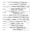
- step S101 the worker causes the handy terminal 80 to read the barcode 40a indicating the device ID of the electronic shelf label 40 attached to the electronic shelf label 40. Thereafter, the process proceeds to step S102.
- step S102 the worker causes the handy terminal 80 to read the barcode (product ID) attached to the product P to be associated with the electronic shelf label 40 whose device ID has been read in step S101. Thereafter, the process proceeds to step S103.
- step S103 the handy terminal 80 associates the device ID of the electronic shelf label 40 and the electronic shelf label 40 with the server communication unit 11 of the electronic shelf label server 10 via a communication line (not shown) (for example, wireless LAN).
- a communication line for example, wireless LAN.
- the product ID of the product P to be sent is transmitted. Thereafter, the process proceeds to step S104.
- step S101 to step S103 is an illustration, and is not limited to this.
- the electronic shelf label system 1 may be designed so that the order in which step S101 and step S102 are performed is reversed. Further, for example, instead of transmitting the device ID and the product ID at the same time in step S103, the transmission of the device ID and the product ID may be executed when each reading is performed.
- step S ⁇ b> 104 the server control unit 15 of the electronic shelf label server 10 links the device ID of the electronic shelf label 40 received by the server communication unit 11 and the product ID of the product P to link the electronic shelf of the server storage unit 14. It is stored in the bill master table 14b. Thereafter, the process proceeds to step S105.
- step S105 the server control unit 15 refers to the product master table 14a in the server storage unit 14 and stores product information (image data) for the product P having the product ID received in step S104 to the electronic shelf label 40. ) Is generated. Thereafter, the process proceeds to step S106.
- step S106 the server control unit 15 refers to the electronic shelf label master table 14b of the server storage unit 14, and the device of the electronic shelf label 40 linked to the product P that requires the display change of the electronic shelf label 40.
- ID that is, the device ID received in step S104
- the process proceeds to step S107.
- step S105 and step S106 do not need to be performed in this order, and the execution order may be reversed. Moreover, step S105 and step S106 may be performed simultaneously.
- step S107 the server control unit 15 generates distribution data including the product information generated in step S105 and the identifier acquired in step S106. Thereafter, the process proceeds to step S108.
- step S108 the server control unit 15 controls the server communication unit 11 to transmit the generated distribution data to the access point 30.
- step S109 the access point 30 that has received the distribution data transmits the distribution data to the electronic shelf label 40 by radio waves.
- step 110 the first communication unit 60 of the electronic shelf label 40 receives the distribution data transmitted by the access point 30. Thereafter, the process proceeds to step S111.
- the operation mode of the control unit 42 of the electronic shelf label 40 (the electronic shelf label 40 attached with the device ID acquired in step S101) that is the transmission target of the distribution data is always set to the wake-up mode as described above. There is no reason. Therefore, in order to avoid a situation where the access point 30 cannot communicate with the electronic shelf label 40, the access point 30 waits until the first communication unit 60 of the electronic shelf label 40 enters the wake-up mode, and then transmits the distribution data.
- step S111 the control unit 42 controls the first communication unit 60 and transmits an ACK signal to the access point 30. Thereafter, the process proceeds to step S112.
- step S112 the control unit 42 writes the product information included in the distribution data received by the first communication unit 60 in the storage unit 43 (updates the product information stored in the storage unit 43). Thereafter, the process proceeds to step S113.
- step S113 the control unit 42 causes the display unit 41 to display the updated product information (image data). In this way, the product information to be displayed by the electronic shelf label 40 is displayed on the display unit 41 of the electronic shelf label 40.
- the electronic shelf label system 1 includes a plurality of electronic shelf labels 40, an electronic shelf label server 10, an access point 30 as a radio wave transmitter, and a remote controller 50 as a portable transmitter.
- the electronic shelf label 40 is arranged corresponding to each of the plurality of products P, and displays product information regarding the corresponding product P.
- the electronic shelf label server 10 stores product information.
- the access point 30 transmits the product information stored in the electronic shelf label server 10 to the plurality of electronic shelf labels 40 by radio waves.
- the remote controller 50 transmits an individual command for the individual electronic shelf label 40 by short-range wireless communication.
- the electronic shelf label 40 includes a first communication unit 60, a second communication unit 70, and a control unit 42.
- the first communication unit 60 receives product information transmitted from the access point 30.
- Second communication unit 70 receives an individual command transmitted from remote controller 50.
- the control part 42 performs the process according to an individual command.
- the electronic shelf label 40 can receive an individual command transmitted from the remote controller 50 by short-range wireless communication. Therefore, it is easy for an operator to operate only the electronic shelf label 40 to be operated without erroneously operating the electronic shelf label 40 other than the operation target at a sales floor where the electronic shelf label 40 is installed.
- the second communication unit 70 includes a memory 73 that stores individual commands.
- the second communication unit 70 writes an individual command in the memory 73 using the power supplied from the remote controller 50 to the second communication unit 70 by non-contact power transmission.
- the writing of the individual command to the memory 73 of the second communication unit 70 of the electronic shelf label 40 is executed by the power supplied from the remote controller 50, the power consumption of the electronic shelf label 40 can be suppressed.
- the electronic shelf label 40 includes a battery 44 that supplies power to the control unit 42.
- the second communication unit 70 has a unit controller 72 that controls the operation of the second communication unit 70.
- the unit controller 72 does not receive power from the battery 44.
- the unit controller 72 of the second communication unit 70 does not use the power of the battery. Further, the second communication unit 70 does not receive power supply from the battery 44 except for the memory 73. Therefore, the frequency of replacement of the battery 44 of the electronic shelf label 40 can be suppressed as compared with the case where the second communication unit 70 performs confirmation of the presence or absence of signal transmission from the remote controller 50 using the power of the battery 44. As a result, the cost of battery replacement (the cost of the battery 44 itself and the labor cost for battery replacement) can be suppressed.
- the unit control unit 72 is an example of a signal transmission unit that transmits a signal to the control unit 42.
- the control unit 42 has a sleep mode (standby mode) that minimizes power consumption and a wake-up mode (startup mode) that consumes more power than the sleep mode as operation modes.
- the unit control unit 72 transmits an interrupt signal for switching the operation mode to the wake-up mode to the control unit 42 in the sleep mode.
- the operation mode of the control unit 42 is switched to the wake-up mode. Therefore, the control unit 42 does not consume the power of the battery 44 because it waits for an input of an individual command from the remote controller 50, which does not know when it will be transmitted. As a result, the replacement frequency of the battery 44 of the electronic shelf label 40 can be suppressed, and the cost of battery replacement can be suppressed.
- the second communication unit 70 is supplied with power from the remote controller 50 by non-contact power transmission.
- the unit controller 72 transmits a signal to the controller 42 using the power supplied from the remote controller 50.
- the unit controller 72 of the second communication unit 70 does not consume the power of the battery 44 for signal transmission to the controller 42, the replacement frequency of the battery 44 of the electronic shelf label 40 can be suppressed, Battery replacement costs can be reduced.
- the communicable distance between the second communication unit 70 and the remote controller 50 is 10 cm or less.
- the link operation between the electronic shelf label 40 and the product P is performed by using the handy terminal 80 with the barcode 40a indicating the device ID of the electronic shelf label 40 and the product ID of the product P.
- the present invention is not limited to this.
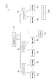
- a configuration like the electronic shelf label system 201 shown below may be used.
- the handy terminal 280 of the electronic shelf label system 201 shown in FIG. 8 has an RF tag reader / writer function.
- the handy terminal 280 acquires the device ID of the electronic shelf label 40 by communicating with the second communication unit 70 of the electronic shelf label 40.
- the link operation is performed according to the flowchart shown in FIG. 9 instead of the flowchart shown in FIG.
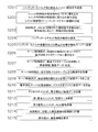
- step S201 the worker sends a device ID transmission command to the handy terminal 280 to the electronic shelf label 40 (to the second communication unit 70 of the electronic shelf label 40) and the activation of the first communication unit 60.
- Commands are transmitted as individual commands. That is, the handy terminal 280 is an example of a portable transmitter.
- step S202 the unit controller 72 of the second communication unit 70 that has received the individual command writes the activation command for the first communication unit 60 into the memory 73 using the power supplied from the handy terminal 280. Further, the unit control unit 72 transmits an interrupt signal to the control unit 42 using the power supplied from the handy terminal 280. Further, the unit control unit 72 transmits the device ID stored in the memory 73 toward the handy terminal 280 in response to a device ID transmission command. The handy terminal 280 receives the device ID transmitted from the second communication unit 70.
- step S203 the control unit 42 that has received the interrupt signal in step S202 changes the operation mode to the wake-up mode and reads the individual command (start command for the first communication unit 60) stored in the memory 73. . Further, the control unit 42 executes the read individual command (start command for the first communication unit 60).
- the start command for the first communication unit 60 is a command for shortening the cycle (standby time) in which the operation mode of the control unit 42 is changed from the sleep mode to the wake-up mode. For example, normally, the standby time in the sleep mode is set to 1 minute. However, when the activation command for the first communication unit 60 is executed, the standby time is 1 second. As a result, the first communication unit 60 can prepare for transmission of product information from the access point 30.
- step S204 the operator causes the handy terminal 280 to read the product ID such as a barcode attached to the product P to be associated with the electronic shelf label 40 that has transmitted the individual command in step S201.
- step S205 the handy terminal 280 sends the device ID of the electronic shelf label 40 acquired in step S202 to the server communication unit 11 of the electronic shelf label server 10 via the communication line (not shown) (for example, wireless LAN) and the electronic The product ID of the product P desired to be associated with the shelf label 40 (the product ID acquired in step S204) is transmitted. Thereafter, the process proceeds to step S206.
- the communication line not shown
- the process proceeds to step S206.
- step S201 to step S205 is an illustration, and is not limited to this.
- the electronic shelf label system 201 may be designed so that step S204 is performed first.
- the device ID and the product ID may be transmitted when they are acquired.
- step S206 the server control unit 15 of the electronic shelf label server 10 links the device ID of the electronic shelf label 40 received by the server communication unit 11 with the product ID of the product P, and the server storage unit 14 Are stored in the electronic shelf label master table 14b. Thereafter, the process proceeds to step S207.
- step S207 the server control unit 15 refers to the product master table 14a in the server storage unit 14 and stores product information (image data) for the product P having the product ID received in step S206 to the electronic shelf label 40. ) Is generated. Thereafter, the process proceeds to step S208.
- step S208 the server control unit 15 refers to the electronic shelf label master table 14b of the server storage unit 14, and the device of the electronic shelf label 40 linked to the product P that requires the display change of the electronic shelf label 40 is performed. ID (that is, the device ID received in step S206) is acquired as an identifier. Thereafter, the process proceeds to step S209.
- step S207 and step S208 do not need to be performed in this order, and the execution order may be reversed. Step S207 and step S208 may be performed simultaneously.
- Steps S209 to S215 are the same as steps S107 to S113 in FIG.
- step S203 the cycle (standby time) in which the operation mode of the control unit 42 becomes the wake-up mode is shortened.
- the control unit 42 can prepare for the transmission of the merchandise information from the access point 30 and can receive the distribution data from the electronic shelf label server 10 in a short time.
- step S301 the operator causes the handy terminal 280 to read a product ID such as a barcode attached to the product P. Thereafter, the process proceeds to step S302.
- step S302 the worker causes the handy terminal 280 to transmit the activation command for the first communication unit 60 and the transmission command for the link request to the second communication unit 70 of the electronic shelf label 40 as individual commands.
- the handy terminal 280 transmits the product ID read in step S301 to the second communication unit 70 together with the individual command.
- the link request is a request transmitted from the electronic shelf label 40 to the electronic shelf label server 10, and the device ID of the electronic shelf label 40 that transmits the link request to the electronic shelf label server 10 and a certain product P Are linked to the product ID (the product ID transmitted to the second communication unit 70 in step S302), and further, the product information of the product P is requested to be transmitted.
- step S303 the unit control unit 72 of the second communication unit 70 that has received the individual command uses the power supplied from the handy terminal 280 to execute the individual command (start command for the first communication unit 60 and transmission command for the link request). ) And the product ID received together with the individual command are written in the memory 73. Further, the unit control unit 72 transmits an interrupt signal to the control unit 42 using the power supplied from the handy terminal 280.
- step S304 the control unit 42 that has received the interrupt signal in step S303 changes the operation mode to the wake-up mode, reads the individual command stored in the memory 73, and executes the content. That is, the control unit 42 shortens a cycle (standby time) in which the operation mode of the control unit 42 becomes the wake-up mode from the sleep mode. Further, the control unit 42 controls the first communication unit 60 to request a link request to the electronic shelf label server 10 together with the device ID stored in the storage unit 43 and the product ID stored in the memory 73. Send.
- step S305 the server control unit 15 of the electronic shelf label server 10 links the device ID of the electronic shelf label 40 received via the access point 30 with the product ID of the product P, and the server storage unit 14 electronic shelf label master table 14b. Thereafter, the process proceeds to step S306.
- step S306 to step S314 are the same as step S207 to step S215 in FIG.
- step S304 Even when the link work is executed according to the flowchart of FIG. 10, in step S304, the cycle (standby time) in which the operation mode of the control unit 42 is changed from the sleep mode to the wake-up mode is shortened. Therefore, when distribution data is transmitted from the access point 30 in step S310, the first communication unit 60 can receive the distribution data in a short time. Therefore, in the electronic shelf label system 201, it is possible to improve the responsiveness of the electronic shelf label 40 at the time of link work compared to the electronic shelf label system 1.
- the time for the access point 30 to transmit the distribution data may also be a short time (for example, 1 second).
- the handy terminal 280 does not need to communicate with the electronic shelf label server 10 during the link work. Therefore, a communication line for enabling communication between the handy terminal 280 and the electronic shelf label server 10 becomes unnecessary.
- the electronic shelf label 40 receives radio waves transmitted from the access point 30 and communicates with the remote controller 50 by short-range wireless communication, but is not limited to this.
- the electronic shelf label may be provided with an infrared transmitter / receiver capable of receiving radio waves transmitted from an access point and communicating with an infrared remote controller.
- Infrared is more directional than radio waves, so in an electronic shelf label system that communicates with access points using radio waves, an operator misoperates an electronic shelf label other than the operation target at the location where the electronic shelf label is installed. Without operation, it is possible to operate only the electronic shelf label to be operated.
- the power consumption of the electronic shelf label can be reduced compared to the case where the remote control and the electronic shelf label communicate with each other by radio waves.
- An electronic shelf label system is an electronic shelf label system in which a server and an electronic shelf label communicate with each other by radio waves.
- An operator erroneously operates an electronic shelf label other than an operation target at an installation location of the electronic shelf label. Therefore, the present invention is useful as an electronic shelf label system that can operate only the electronic shelf label to be operated.
- Electronic shelf label system 10 Electronic shelf label server (server) 30 access point (radio wave transmitter) 40 Electronic shelf label 42 Control unit (processing unit) 44 Battery 50 Remote control (portable transmitter) 60 First communication unit (first receiving unit) 70 Second communication unit (second receiving unit) 72 Unit controller (signal transmitter) 73 Memory 280 Handy terminal (portable transmitter) P product
Landscapes
- Engineering & Computer Science (AREA)
- Theoretical Computer Science (AREA)
- Human Computer Interaction (AREA)
- Physics & Mathematics (AREA)
- General Engineering & Computer Science (AREA)
- General Physics & Mathematics (AREA)
- Display Racks (AREA)
- Cash Registers Or Receiving Machines (AREA)
Abstract
サーバと電子棚札とが電波により通信を行う電子棚札システムにおいて、電子棚札の設置場所で、作業者が、操作対象以外の電子棚札を誤操作することなく、操作対象の電子棚札だけを操作することが可能な電子棚札システムを提供する。電子棚札システムは、商品情報を表示する複数の電子棚札(40)と、商品情報を記憶する電子棚札サーバと、アクセスポイントと、リモコンと、を備える。アクセスポイントは、複数の電子棚札に向けて、商品情報を電波により送信する。リモコンは、個別の電子棚札に対する個別指令を、近距離無線通信により送信する。電子棚札は、第1通信ユニット(60)と、第2通信ユニット(70)と、制御部(42)と、を有する。第1通信ユニットは、アクセスポイントから送信される商品情報を受信する。第2受信ユニットは、リモコンから送信される個別指令を受信する。制御部は、個別指令に応じた処理を実行する。
Description
本発明は、電波でサーバとの情報のやり取りを行う、電波式の電子棚札システムに関する。
従来、スーパーマーケットやコンビニエンスストア等の店舗では、電波式の電子棚札システムが採用されている(例えば、特許文献1(特開2001-148074号公報))。電波式の電子棚札システムでは、商品情報を管理するサーバから、売り場等に設置された電子棚札に電波で商品情報が送信され、受信した商品情報に基づいて電子棚札の表示内容が変更される。
ところで、このような電子棚札システムを用いる場合に、店舗の従業員等の作業者が、電子棚札の設置された売り場で、ある特定の電子棚札の表示を通常画面(顧客向けの表示画面)から管理画面(作業者が商品管理に用いる表示画面)へと切り換えたり、ある特定の電子棚札に記憶される情報を変更したりすることが必要な場合がある。このような場合に、作業者が、可搬型の電波式リモコンを用いて、電子棚札の設置された売り場で電子棚札の操作を行うことがある。
しかし、電波式リモコンを用いて特定の電子棚札を操作しようとする場合、電波は一般に指向性が低いため、操作対象ではない他の電子棚札も誤操作してしまう場合がある。特に、店舗の売り場では、電子棚札が互いに近接して配置されることも多く、このような誤操作が発生しやすい。誤操作の発生を抑制するためには、リモコンから送信される電波の指向性を向上させることが必要となり、リモコンのアンテナ設計が容易ではない。
本発明の課題は、サーバと電子棚札とが電波により通信を行う電子棚札システムにおいて、作業者が、電子棚札の設置場所で、操作対象以外の電子棚札を誤操作することなく、操作対象の電子棚札だけを操作することが可能な電子棚札システムを提供することにある。
本発明に係る電子棚札システムは、複数の電子棚札と、サーバと、電波送信機と、携帯型送信機と、を備える。電子棚札は、複数の商品のそれぞれに対応して配置され、対応する商品に関する商品情報を表示する。サーバは、商品情報を記憶する。電波送信機は、複数の電子棚札に向けて、サーバに記憶された商品情報を電波により送信する。携帯型送信機は、個別の電子棚札に対する個別指令を、近距離無線通信により送信する。電子棚札は、第1受信ユニットと、第2受信ユニットと、処理部と、を有する。第1受信ユニットは、電波送信機から送信される商品情報を受信する。第2受信ユニットは、携帯型送信機から送信される個別指令を受信する。処理部は、個別指令に応じた処理を実行する。
ここでは、電子棚札が、携帯型送信機から近距離無線通信(NFC: Near Field Communication)により送信される個別指令を受信できる。そのため、電子棚札の設置された売り場等で、作業者が、操作対象以外の電子棚札を誤操作することなく、操作対象の電子棚札だけを操作することが容易である。
また、本発明に係る電子棚札システムでは、第2受信ユニットは、個別指令を記憶するメモリを有することが望ましい。第2受信ユニットは、携帯型送信機から第2受信ユニットに対して非接触電力伝送により供給される電力を用いて、メモリに個別指令を書き込むことが望ましい。
ここでは、電子棚札の第2受信ユニットのメモリに対する個別指令の書き込みが、携帯型送信機により供給された電力により実行されるため、電子棚札の電力消費を抑制することができる。
また、本発明に係る電子棚札システムでは、電子棚札は、処理部に電力を供給する電池を更に有することが望ましい。第2受信ユニットは、第2受信ユニットの動作を制御するユニット制御部を更に有することが望ましい。ユニット制御部は、電池から電力の供給を受けないことが望ましい。
ここでは、電池駆動式の電子棚札において、第2受信ユニットのユニット制御部が、電池の電力を使用しない。そのため、ユニット制御部が、携帯型送信機からの信号送信の有無の確認を、電池の電力を用いて実行する場合に比べ、電子棚札の電池の交換頻度を抑制できる。その結果、電池交換のコスト(電池自体のコストや、電池交換のための人件費)を抑制できる。
また、本発明に係る電子棚札システムでは、電子棚札は、処理部に電力を供給する電池を更に有することが望ましい。第2受信ユニットは、処理部に信号を送信する信号送信部を有することが望ましい。処理部は、消費電力を最小限に抑制する待機モードと、待機モードよりも消費電力の大きな起動モードと、を動作モードとして有することが望ましい。信号送信部は、第2受信ユニットが個別指令を受信すると、待機モードにある処理部に対し、動作モードを起動モードに切り換えるための信号を送信することが望ましい。
ここでは、電池駆動式の電子棚札において、第2受信ユニットが個別指令を受け付けてから、処理部の動作モードが起動モードに切り換えられる。そのため、処理部は、いつ送信されてくるかわからない携帯型送信機からの個別指令の入力待ちのために、電池の電力を消耗することがない。その結果、電子棚札の電池の交換頻度を抑制でき、電池交換のコストを抑制できる。
さらに、本発明に係る電子棚札システムでは、第2受信ユニットは、携帯型送信機から非接触電力伝送により電力の供給を受けることが望ましい。信号送信部は、携帯型送信機から供給された電力を用いて処理部に信号を送信することが望ましい。
ここでは、第2受信ユニットの信号送信部が、処理部に対する信号送信のために電池の電力を消耗することがないので、電子棚札の電池の交換頻度を抑制でき、電池交換のコストを抑制できる。
また、本発明に係る電子棚札システムでは、第2受信ユニットと携帯型送信機との通信可能距離は10cm以下であることが望ましい。
これにより、店舗の売り場等で、電子棚札が密接して設置されている場合でも、操作対象以外の電子棚札を誤操作することなく、操作対象の電子棚札だけを操作することができる。
本発明に係る電子棚札システムでは、電子棚札が、携帯型送信機から近距離無線通信により送信される個別指令を受信できる。そのため、電子棚札の設置された売り場等で、作業者が、操作対象以外の電子棚札を誤操作することなく、操作対象の電子棚札だけを操作することが容易である。
以下、図面を参照しながら、本発明の一実施形態に係る電子棚札システム1について説明する。
なお、本実施形態に係る電子棚札システム1は、本発明の実施形態の例示に過ぎず、本発明に係る電子棚札システムは、以下に記載する内容に限定されるものではない。発明の趣旨と矛盾しない範囲で、その他の態様も採用可能である。
(1)全体構成
電子棚札システム1は、スーパーマーケットやコンビニエンスストアのような店舗において使用される。
電子棚札システム1は、スーパーマーケットやコンビニエンスストアのような店舗において使用される。
電子棚札システム1は、図1に示すように、主として、複数の電子棚札40,40,・・・と、電子棚札サーバ10と、複数のアクセスポイント30,30,・・・と、リモコン50と、ハンディターミナル80と、から構成されている。電子棚札システム1に含まれる電子棚札40、アクセスポイント30、リモコン50、および、ハンディターミナル80の台数は、図1に示される数に限定されるものではない。
電子棚札40は、可搬性の装置であり、店舗で取り扱われる複数の商品Pのそれぞれに対応して配置される表示装置である。電子棚札40は、店舗の売り場に陳列される複数の種類の商品Pのうち、対応する商品Pの近傍に配置され、対応する商品Pに関する商品情報を表示する(図2参照)。商品情報は、商品Pに関する種々の情報であり、例えば、商品Pの通常販売価格、特別販売価格、割引率、売上数量、在庫数量等を含む。
電子棚札サーバ10は、電子棚札システム1を統括的に制御するコンピュータである。電子棚札サーバ10の機能には、電子棚札40に表示される商品情報の管理を含む。商品情報は、後述するように、電子棚札サーバ10のサーバ記憶部14に記憶されている。電子棚札サーバ10は、アクセスポイント30を介して、電子棚札40に、商品情報を含む配信データを送信する。なお、ここでは、電子棚札サーバ10は、電子棚札40に対して、商品情報を画像データ(後述する電子棚札40の表示部41に表示される画像のデータ)として送信するが、これに限定されるものではない。例えば、電子棚札サーバ10は、電子棚札40に対し、通常販売価格等の商品情報を数値データとして送信してもよい。
アクセスポイント30は、電波の送受信機である。アクセスポイント30は、電子棚札40との間で、電波を用いて各種信号の授受を行う。アクセスポイント30は、例えば店舗内の天井に、一定の間隔を空けて取り付けられる。アクセスポイント30の設置場所や設置間隔等は、店舗内に設置された電子棚札40が、いずれかのアクセスポイント30と通信可能となるように決定される。アクセスポイント30は、LAN(Local Area Network)等のネットワーク2を介して、電子棚札サーバ10と接続されている。
アクセスポイント30は、ネットワーク2を介して電子棚札サーバ10からアクセスポイント30に送信される配信データ(商品情報を含む配信データ)を、複数の電子棚札40に向けて電波により送信する。つまり、アクセスポイント30は、電波送信機の一例である。また、アクセスポイント30は、電子棚札40から送信される信号を受信し、受信した信号を、ネットワーク2を介して電子棚札サーバ10に送信する。
リモコン50は、携帯型の送受信機である。リモコン50は、各電子棚札40との間で、近距離無線通信(NFC: Near Field Communication)を用いて各種信号の授受を行う。なお、ここでの、近距離無線通信は、数cm~数十cm程の距離での通信を意味する。リモコン50は、個別の電子棚札40に対する個別指令を、電磁界を用いた近距離無線通信により送信する。つまり、リモコン50は、携帯型送信機の一例である。
ハンディターミナル80は、後述するように、電子棚札40や商品Pに付されたバーコードなどの識別情報を読み取り可能に構成され、主に情報収集のために用いられる携帯型の情報端末である。ハンディターミナル80は、主に、電子棚札40の装置IDと、商品Pの商品IDとのリンク作業に用いられる。リンク作業については後述する。
(2)詳細構成
電子棚札システム1の電子棚札40、電子棚札サーバ10、およびリモコン50について以下に詳細に説明する。
電子棚札システム1の電子棚札40、電子棚札サーバ10、およびリモコン50について以下に詳細に説明する。
(2-1)電子棚札
電子棚札40は、上述のように、店舗で取り扱われる複数の商品Pのそれぞれに対応して配置され、対応する商品Pに関する商品情報を表示する(図2参照)。例えば、電子棚札40には、商品Pの商品名、重量あたりの単価、および販売価格が、商品情報として表示される(図3参照)。
電子棚札40は、上述のように、店舗で取り扱われる複数の商品Pのそれぞれに対応して配置され、対応する商品Pに関する商品情報を表示する(図2参照)。例えば、電子棚札40には、商品Pの商品名、重量あたりの単価、および販売価格が、商品情報として表示される(図3参照)。
電子棚札40は、図4のように、主に表示部41、制御部42、記憶部43、電池44、第1通信ユニット60、および第2通信ユニット70を有する。
(2-1-1)表示部
表示部41は、後述する記憶部43に記憶されている商品情報を表示させるための画面である(図3参照)。表示部41には、電子ペーパが用いられる。すなわち、表示部41は、マトリクス状に配列された複数の画素で構成される、ドットマトリクス方式の不揮発性表示部である。表示部41は、電力を供給されなくても表示内容を保持することが可能である。なお、表示部41は電子ペーパに限定されるものではなく、例えば、液晶ディスプレイが用いられてもよい。
表示部41は、後述する記憶部43に記憶されている商品情報を表示させるための画面である(図3参照)。表示部41には、電子ペーパが用いられる。すなわち、表示部41は、マトリクス状に配列された複数の画素で構成される、ドットマトリクス方式の不揮発性表示部である。表示部41は、電力を供給されなくても表示内容を保持することが可能である。なお、表示部41は電子ペーパに限定されるものではなく、例えば、液晶ディスプレイが用いられてもよい。
表示部41に表示される画面には、通常画面と、管理画面と、がある。通常画面は、顧客向けの画面であり、表示部41には、例えば、商品Pの商品名、重量あたりの単価、および販売価格が、商品情報として表示される(図3参照)。管理画面は、店舗の店員等の作業者が商品管理に用いる画面であり、表示部41には、例えば、商品Pの売上数、発注数、在庫数が、商品情報として表示される。
作業者は、電子棚札40が設置されている現場で、リモコン50により電子棚札40を操作することで(リモコン50から第2通信ユニット70に対して個別指令を送信することで)、表示部41の表示を、通常画面から管理画面に切り換えることができる。
(2-1-2)制御部
制御部42は、処理部の一例である。制御部42は、主にCPUによって構成される。制御部42は、表示部41、記憶部43、第1通信ユニット60、および第2通信ユニット70と電気的に接続されている(図4の実線参照)。制御部42は、電池44から駆動電力の供給を受ける(図4の破線参照)。
制御部42は、処理部の一例である。制御部42は、主にCPUによって構成される。制御部42は、表示部41、記憶部43、第1通信ユニット60、および第2通信ユニット70と電気的に接続されている(図4の実線参照)。制御部42は、電池44から駆動電力の供給を受ける(図4の破線参照)。
制御部42は、後述する記憶部43に記憶されたプログラムを実行することで、電子棚札40の各部を制御する。例えば、制御部42は、表示部41に、後述する第1通信ユニット60が電子棚札サーバ10から受信した商品情報(画像データ)が表示されるように、表示部41の制御を行う。また、例えば、制御部42は、後述する第2通信ユニット70が受信した個別指令に応じた処理を実行するために、表示部41、記憶部43、第1通信ユニット60の動作を制御する。
なお、個別指令は、後述するリモコン50から、個別の電子棚札40に対して送信される指令である。個別指令には、例えば、表示部41の表示を通常画面から管理画面へと切り換える指令を含む。また、例えば、個別指令には、第1通信ユニット60を、アクセスポイント30から送信される配信データを受信可能になるように制御する指令を含む。
制御部42は、動作モードとして、スリープモード(待機モード)およびウェイクアップモード(起動モード)を有する。
スリープモードは、電子棚札40の消費電力を最小限に抑制する(電池44の消耗を最低限に抑制する)モードである。スリープモードでは、制御部42は、表示部41、記憶部43、第1通信ユニット60および第2通信ユニット70のメモリ73に対して、電池44から電力が供給されないように制御する。そのため、スリープモードでは、表示部41の表示の更新や、表示部41の表示の通常画面から管理画面への切り換えや、第1通信ユニット60による電波の受信が実行できない。
ウェイクアップモードは、電子棚札40の種々の機能、例えば、表示部41の表示の更新や、表示部41の表示の通常画面から管理画面への切り換えや、第1通信ユニット60による電波の受信を実行可能な動作モードである。制御部42は、ウェイクアップモードでは、電池44から、表示部41、記憶部43、第1通信ユニット60およびメモリ73に対して、必要に応じて電力が供給されるよう制御する。そのため、ウェイクアップモード時の電子棚札40の消費電力は、スリープモード時の電子棚札40の消費電力より大きい。
制御部42の動作モードは、電池44の消耗を抑制するため、スリープモードである時間が長い(動作モードがスリープモードである時間の比率が高い)。そして、以下の2つの条件のうち、いずれかの条件が成立する場合に、制御部42の動作モードは、スリープモードからウェイクアップモードへと切り換えられる。
1つ目の条件(第1条件)は、動作モードがスリープモードに切り換えられた後、所定の待機時間が経過することである。言い換えれば、第1条件は、タイマ機能を有する制御部42が、動作モードがスリープモードに切り換えられてから所定の待機時間が経過したと判定することである。
待機時間は、例えば1分であるが、これに限定されるものではない。ただし、制御部42が頻繁にウェイクアップモードに移行すると、電池44が消耗しやすいため、電子棚札サーバ10からの商品情報の送信に対する反応時間が、電子棚札システム1のユーザにとって許容可能な範囲で、待機時間はできるだけ長い時間とされることが望ましい。なお、電子棚札サーバ10からの商品情報の送信に対する反応時間とは、電子棚札サーバ10が商品情報を送信してから、表示部41の表示にその内容が反映されるまでの時間を意味する。
本実施形態のリモコン50に代えて電波式のリモコンが使用される場合、電子棚札がリモコンの電波を受信するためには、電子棚札の電波受信ユニットは予め(リモコンからの電波の送信前に)起動している必要がある。言い換えれば、電波式のリモコンが使用される場合、電子棚札がリモコンの電波を受信するためには、電子棚札の制御部の動作モードが、予めウェイクアップモードに切り換えられている必要がある。リモコンから送信される個別指令に対する電子棚札の反応性が悪い場合、作業者の待ち時間が長くなり、作業効率が悪いことから、待機時間は、短い時間(例えば1秒)に設定される必要がある。
しかし、本実施形態では、後述するように、リモコン50からの個別指令の送信に備えて、制御部42の動作モードをスリープモードからウェイクアップモードへと予め切り換える必要が無いため、待機時間を長く取ることが可能である。
第1条件が成立すると、制御部42の動作モードが、スリープモードから、ウェイクアップモードへと切り換えられる。そして、制御部42は、第1通信ユニット60に電池44から駆動電力が供給されるよう制御し、第1通信ユニット60がアクセスポイント30から送信される配信データを受信可能な状態になるよう制御する。
そして、制御部42は、第1通信ユニット60が配信データを受信すると、受信した配信データが、自己に対して送信された(その電子棚札40に対して送信された)配信データであるか否かを判定する。
受信した配信データが、自己に対して送信された配信データであると判定された場合には、制御部42は、引き続き必要な処理を実行する。具体的には、例えば、制御部42は、自己に対して送信された配信データを受信した旨を示す信号(ACK信号)をアクセスポイント30に対して送信させるように、第1通信ユニット60を制御する。また、例えば、制御部42は、自己に対して送信された配信データに含まれる商品情報(画像データ)を、記憶部43に書き込む(記憶部43に記憶される商品情報の更新処理を行う)。また、例えば、制御部42は、表示部41の表示内容が、記憶部43に書き込まれた商品情報に変更されるように、表示部41を制御する。必要な処理が終了すると、制御部42の動作モードは、スリープモードへと切り換えられる。
一方、受信した配信データが、自己に対して送信された配信データではないと判定された場合、あるいは、第1通信ユニット60が所定時間内に配信データを受信しない場合には、制御部42の動作モードは、スリープモードへと切り換えられる。
なお、制御部42は、第1通信ユニット60が受信した配信データが、自己に対して送信されたものであるか否かを、以下のようにして判定する。
後述するように、電子棚札サーバ10がアクセスポイント30を介して送信する配信データには、商品情報と識別子とが含まれる。識別子は、商品情報の送信対象の電子棚札40の装置ID(各電子棚札40に割り当てられる固有のID)である。制御部42は、第1通信ユニット60が受信した信号に含まれる識別子と、後述する記憶部43に記憶されている自己の装置IDとを比較し、両者が一致すると、その信号が自己に対して送信された配信データであると判定する。
制御部42の動作モードが、スリープモードからウェイクアップモードへと切り換えられる2つ目の条件(第2条件)は、後述する第2通信ユニット70のユニット制御部72が送信する割り込み信号を、制御部42が受信することである。第2条件が成立すると、制御部42の動作モードが、スリープモードから、ウェイクアップモードへと切り換えられる。第2条件が成立すると、制御部42は、後述する第2通信ユニット70のメモリ73に記憶された個別指令を読み出し、その個別指令に応じた処理を実行する。
(2-1-3)記憶部
記憶部43は、EEPROM等の不揮発性メモリによって構成される記憶部である。ただし、これに限定されるものではなく、記憶部43にRAM等の揮発性メモリが使用されてもよい。ただし、記憶部43に揮発性メモリを利用した場合には、制御部42がスリープモードにある場合にも、記憶された情報を保持するために電力を供給する必要があるため、電池44の消耗を抑制する上で、記憶部43は不揮発性メモリであることが望ましい。
記憶部43は、EEPROM等の不揮発性メモリによって構成される記憶部である。ただし、これに限定されるものではなく、記憶部43にRAM等の揮発性メモリが使用されてもよい。ただし、記憶部43に揮発性メモリを利用した場合には、制御部42がスリープモードにある場合にも、記憶された情報を保持するために電力を供給する必要があるため、電池44の消耗を抑制する上で、記憶部43は不揮発性メモリであることが望ましい。
記憶部43には、制御部42が電子棚札40の各部の制御を行うためのプログラムの他、電子棚札40の固有の識別子である装置IDや、電子棚札サーバ10から送信された商品情報(画像データ)が記憶される。商品情報には、通常画面用の商品情報と、管理画面用の商品情報とが含まれる。
(2-1-4)電池
電池44は、電子棚札40の表示部41、制御部42、記憶部43、第1通信ユニット60、および後述する第2通信ユニット70のメモリ73に駆動電力を供給する(図4の破線参照)。なお、後述するように、第2通信ユニット70は、リモコン50から供給される電力を利用するため、メモリ73を除き、電池44からの電力の供給は受けない。言い換えれば、後述する第2通信ユニット70のユニット制御部72およびアンテナ71は、電池44からの電力の供給を受けない。後述する第2通信ユニット70のメモリ73は、電池44とリモコン50との双方から電力供給を受けることができる。
電池44は、電子棚札40の表示部41、制御部42、記憶部43、第1通信ユニット60、および後述する第2通信ユニット70のメモリ73に駆動電力を供給する(図4の破線参照)。なお、後述するように、第2通信ユニット70は、リモコン50から供給される電力を利用するため、メモリ73を除き、電池44からの電力の供給は受けない。言い換えれば、後述する第2通信ユニット70のユニット制御部72およびアンテナ71は、電池44からの電力の供給を受けない。後述する第2通信ユニット70のメモリ73は、電池44とリモコン50との双方から電力供給を受けることができる。
表示部41、記憶部43、第1通信ユニット60および第2通信ユニット70のメモリ73には、FET等のスイッチ(図示せず)がそれぞれ設けられている。制御部42は、これらのスイッチを制御することで、表示部41、記憶部43、第1通信ユニット60およびメモリ73への電力の供給を制御する。
上記のように、電子棚札40の動作モードが、ウェイクアップモードからスリープモードへと切り換えられる場合には、制御部42は、上記のスイッチをオフにすることで、表示部41、記憶部43、第1通信ユニット60およびメモリ73に電池44から電力が供給されないように制御を行う。
(2-1-5)第1通信ユニット
第1通信ユニット60は、第1受信ユニットの一例である。第1通信ユニット60は、アクセスポイント30から、電波により送信される配信データ(他の電子棚札40を送信対象とする配信データを含む)を受信する。また、第1通信ユニット60は、自己に対して送信された配信データを受信した場合に(第1通信ユニット60が受信した配信データが、自己に対して送信された配信データであると、制御部42が判定する場合に)、制御部42の指示に従い、自己に対して送信された配信データを受信した旨の信号(ACK信号)を、アクセスポイント30に対して、電波により送信する。
第1通信ユニット60は、第1受信ユニットの一例である。第1通信ユニット60は、アクセスポイント30から、電波により送信される配信データ(他の電子棚札40を送信対象とする配信データを含む)を受信する。また、第1通信ユニット60は、自己に対して送信された配信データを受信した場合に(第1通信ユニット60が受信した配信データが、自己に対して送信された配信データであると、制御部42が判定する場合に)、制御部42の指示に従い、自己に対して送信された配信データを受信した旨の信号(ACK信号)を、アクセスポイント30に対して、電波により送信する。
(2-1-6)第2通信ユニット
第2通信ユニット70は、リモコン50から送信される個別指令を受信する。第2通信ユニット70は、第2受信ユニットの一例である。
第2通信ユニット70は、リモコン50から送信される個別指令を受信する。第2通信ユニット70は、第2受信ユニットの一例である。
第2通信ユニット70は、パッシブ型のRFタグである。つまり、第2通信ユニット70は、リモコン50から非接触電力伝送により電力の供給を受けるRFタグである。第2通信ユニット70は、後述するメモリ73を除き、電池44からの電力供給は受けない。なお、第2通信ユニット70は、電磁誘導方式のRFタグであるが、これに限定されるものではなく、例えば、電波方式のRFタグが用いられてもよい。第2通信ユニット70は、図4のように、主にアンテナ71と、ユニット制御部72と、メモリ73と、を有する。
(2-1-6-1)アンテナ
アンテナ71は、電磁波の送受信に用いられるループアンテナ(コイルアンテナ)である。なお、第2通信ユニット70とリモコン50との通信可能距離は、ここでは10cm以下である。通信可能距離は、これに限定されるものではないが、電子棚札40同士が近接して配置される場合(例えば、図2中で右上に描写されている2台の電子棚札40のように、隣接して配置される場合)に、リモコン50が通信対象ではない電子棚札40を誤って操作することがないように、通信可能距離は10cm以下であることが望ましい。
アンテナ71は、電磁波の送受信に用いられるループアンテナ(コイルアンテナ)である。なお、第2通信ユニット70とリモコン50との通信可能距離は、ここでは10cm以下である。通信可能距離は、これに限定されるものではないが、電子棚札40同士が近接して配置される場合(例えば、図2中で右上に描写されている2台の電子棚札40のように、隣接して配置される場合)に、リモコン50が通信対象ではない電子棚札40を誤って操作することがないように、通信可能距離は10cm以下であることが望ましい。
(2-1-6-2)ユニット制御部
ユニット制御部72は、リモコン50からの個別指令に応じて、第2通信ユニット70を制御するRF通信チップである。
ユニット制御部72は、リモコン50からの個別指令に応じて、第2通信ユニット70を制御するRF通信チップである。
ユニット制御部72は、前述のように、リモコン50から第2通信ユニット70に対して非接触電力伝送により供給される電力を用いて、各種処理を実行する。
例えば、ユニット制御部72は、アンテナ71を介してリモコン50から個別指令を受信すると、リモコン50から第2通信ユニット70に対して非接触電力伝送により供給される電力を用いて、受け付けた個別指令の内容をメモリ73に書き込む。
また、例えば、ユニット制御部72は、アンテナ71を介してリモコン50から個別指令を受信すると、リモコン50から第2通信ユニット70に対して非接触電力伝送により供給される電力を用いて、制御部42に対して割り込み信号を送信する。つまり、ユニット制御部72は、信号送信部の一例である。割り込み信号は、制御部42に、第2通信ユニット70がリモコン50からの個別指令を受信したことを知らせるための信号である。制御部42は、割り込み信号を受信すると、メモリ73に記憶された個別指令(リモコン50から送信された個別指令)を読み出す。その後、制御部42は、メモリ73から読み出した個別指令に応じた処理を実行する。なお、制御部42の動作モードがスリープモードにある場合に、制御部42がユニット制御部72からの割り込み信号を受信すると、まず制御部42の動作モードがウェイクアップモードに切り換えられ、その後、制御部42は、個別指令を読み出し、読み出した個別指令を実行する。
また、ユニット制御部72は、個別指令がメモリ73に記憶されている情報の送信を要求するものである場合には、メモリ73に記憶されている情報を読み出して、読み出した情報をリモコン50に対して送信する。
(2-1-6-3)メモリ
メモリ73は、EEPROM等の不揮発性メモリにより構成される。メモリ73は、電池44およびリモコン50の双方から、電力供給を受けることができる。
メモリ73は、EEPROM等の不揮発性メモリにより構成される。メモリ73は、電池44およびリモコン50の双方から、電力供給を受けることができる。
メモリ73には、ユニット制御部72が、アンテナ71を介してリモコン50から受信した個別指令が書き込まれる。また、メモリ73には、例えば、電子棚札の装置IDが記憶されている。なお、メモリ73に記憶されている装置IDは、記憶部43に記憶される装置IDと同一の情報である。
(2-2)電子棚札サーバ
電子棚札サーバ10は、電子棚札システム1を統括的に管理するコンピュータである。電子棚札サーバ10は、アクセスポイント30を介して、電子棚札40に各種指令や各種情報を送信する。電子棚札サーバ10から電子棚札40に送信する情報には、商品情報を含む。電子棚札サーバ10は、店舗のバックヤード等に配置される。
電子棚札サーバ10は、電子棚札システム1を統括的に管理するコンピュータである。電子棚札サーバ10は、アクセスポイント30を介して、電子棚札40に各種指令や各種情報を送信する。電子棚札サーバ10から電子棚札40に送信する情報には、商品情報を含む。電子棚札サーバ10は、店舗のバックヤード等に配置される。
電子棚札サーバ10は、主な機能部として、サーバ通信部11と、サーバ表示部12と、サーバ入力部13と、サーバ記憶部14と、サーバ制御部15とを有する(図5参照)。
(2-2-1)サーバ通信部
サーバ通信部11は、電子棚札サーバ10と、アクセスポイント30や、ハンディターミナル80等との通信を可能にするための通信インターフェースである。また、サーバ通信部11は、電子棚札システム1外の機器(例えば、店舗に電子棚札システム1と共に設置されるPOSシステムのサーバおよびストアコントローラ)とも通信可能に構成されている。サーバ通信部11からアクセスポイント30に送られた配信データは、さらにアクセスポイント30により電子棚札40へと電波により送信される。
サーバ通信部11は、電子棚札サーバ10と、アクセスポイント30や、ハンディターミナル80等との通信を可能にするための通信インターフェースである。また、サーバ通信部11は、電子棚札システム1外の機器(例えば、店舗に電子棚札システム1と共に設置されるPOSシステムのサーバおよびストアコントローラ)とも通信可能に構成されている。サーバ通信部11からアクセスポイント30に送られた配信データは、さらにアクセスポイント30により電子棚札40へと電波により送信される。
(2-2-2)サーバ表示部
サーバ表示部12は、液晶ディスプレイである。サーバ表示部12には、電子棚札システム1に関する各種情報を表示可能である。
サーバ表示部12は、液晶ディスプレイである。サーバ表示部12には、電子棚札システム1に関する各種情報を表示可能である。
(2-2-3)サーバ入力部
サーバ入力部13は、マウスおよびキーボードである。電子棚札システム1のユーザは、電子棚札サーバ10に対する各種指令や各種情報を、サーバ入力部13を介して入力可能である。
サーバ入力部13は、マウスおよびキーボードである。電子棚札システム1のユーザは、電子棚札サーバ10に対する各種指令や各種情報を、サーバ入力部13を介して入力可能である。
(2-2-4)サーバ記憶部
サーバ記憶部14は、ROM、RAM、およびハードディスク等により構成される。サーバ記憶部14には、後述するサーバ制御部15により実行される各種プログラムが記憶される。また、サーバ記憶部14には、各種情報が記憶される。サーバ記憶部14に記憶される情報には、商品マスタテーブル14aと、電子棚札マスタテーブル14bとが含まれる(図5参照)。
サーバ記憶部14は、ROM、RAM、およびハードディスク等により構成される。サーバ記憶部14には、後述するサーバ制御部15により実行される各種プログラムが記憶される。また、サーバ記憶部14には、各種情報が記憶される。サーバ記憶部14に記憶される情報には、商品マスタテーブル14aと、電子棚札マスタテーブル14bとが含まれる(図5参照)。
(2-2-4-1)商品マスタテーブル
商品マスタテーブル14aは、電子棚札システム1で取り扱う商品に関する情報(商品情報)を記憶する。商品情報は、商品Pに関する種々の情報であり、例えば、商品Pの商品名、価格(通常販売価格、特別販売価格)、単価(通常販売単価・特別販売単価)、割引率、売上数量、在庫数量等を含む。商品マスタテーブル14aには、商品ID(商品Pのバーコード情報)別に、商品情報が記憶される。
商品マスタテーブル14aは、電子棚札システム1で取り扱う商品に関する情報(商品情報)を記憶する。商品情報は、商品Pに関する種々の情報であり、例えば、商品Pの商品名、価格(通常販売価格、特別販売価格)、単価(通常販売単価・特別販売単価)、割引率、売上数量、在庫数量等を含む。商品マスタテーブル14aには、商品ID(商品Pのバーコード情報)別に、商品情報が記憶される。
商品マスタテーブル14aの内容は、サーバ通信部11が外部機器(例えば、店舗内に設置される図示しないPOSシステム)から情報を受信することで、あるいは、サーバ入力部13が情報の入力を受け付けることで更新される。
(2-2-4-2)電子棚札マスタテーブル
電子棚札マスタテーブル14bには、電子棚札40を識別するための装置IDと、商品Pの商品IDとが、関連付けて(リンク付けて)記憶されている。電子棚札40の装置IDと、商品Pの商品IDとは、作業者が、ハンディターミナル80を用いてリンク作業を行うことで関連付けされる。なお、ハンディターミナル80は、電子棚札40や商品Pに付されたバーコードなどの識別情報を読み取り可能に構成され、主に情報収集のために用いられる携帯型の情報端末である。
電子棚札マスタテーブル14bには、電子棚札40を識別するための装置IDと、商品Pの商品IDとが、関連付けて(リンク付けて)記憶されている。電子棚札40の装置IDと、商品Pの商品IDとは、作業者が、ハンディターミナル80を用いてリンク作業を行うことで関連付けされる。なお、ハンディターミナル80は、電子棚札40や商品Pに付されたバーコードなどの識別情報を読み取り可能に構成され、主に情報収集のために用いられる携帯型の情報端末である。
なお、リンク作業は、以下のように実施される。作業者は、1の電子棚札40に付された、その電子棚札40の装置ID(電子棚札40の記憶部43およびメモリ73に記憶されている装置IDと同じもの)を表示するバーコード40a(図3参照)を、ハンディターミナル80のリーダでスキャンする。続いて、作業者は、その電子棚札40が商品情報を表示する商品Pに付されたバーコードを、ハンディターミナル80のリーダでスキャンする。スキャンされた装置IDおよび商品IDは、図示しない通信回線(例えば無線LAN)を介して電子棚札サーバ10に送信される。後述するサーバ制御部15は、送信された電子棚札40の装置IDと、商品Pの商品IDとをリンクさせて、電子棚札マスタテーブル14bに記憶させる。
(2-2-5)サーバ制御部
サーバ制御部15は、サーバ記憶部14に記憶されているプログラムや各種情報に基づいて各種制御を行う。
サーバ制御部15は、サーバ記憶部14に記憶されているプログラムや各種情報に基づいて各種制御を行う。
例えば、サーバ制御部15は、サーバ通信部11が、ハンディターミナル80から送信される、リンク付けするべき電子棚札の装置IDと商品Pの商品IDとを受け付けると、その情報を電子棚札マスタテーブル14bにリンク付けして記憶する。
また、サーバ制御部15は、電子棚札システム1の起動時や、電子棚札40の表示変更が必要な時に、アクセスポイント30を介して、電子棚札40に商品情報を送信する。電子棚札40の表示変更が必要な時とは、例えば、商品マスタテーブル14aの内容が更新された時や、商品Pの特売期間に価格を通常販売価格から特別販売価格へと変更する時や、商品Pの特売期間終了時に価格を特別販売価格から通常販売価格へと変更する時である。
サーバ制御部15は、電子棚札40に対して商品情報を送信する際に、具体的には、以下の処理を行う。
まず、サーバ制御部15は、商品マスタテーブル14aを参照して、電子棚札40の表示変更が必要な商品Pについて、電子棚札40に送信するための商品情報(画像データ)を生成する。また、サーバ制御部15は、電子棚札マスタテーブル14bを参照して、電子棚札40の表示変更が必要な商品Pとリンク付けされている電子棚札40の装置IDを、識別子として取得する。
次に、サーバ制御部15は、生成した画面情報と、取得した識別子(送信対象の電子棚札40の装置ID)とを含めて配信データを生成する。例えば、配信データは、識別子を含んだヘッダと、商品情報とを組み合わせたデータである。
さらに、サーバ制御部15は、生成された配信データを、アクセスポイント30に送信する。配信データを受信したアクセスポイント30は、その配信データを、電波により電子棚札40に対して送信する。
なお、前述のように、電子棚札40の第1通信ユニット60は、制御部42の動作モードがスリープモードに切り換えられると、第2通信ユニット70がリモコン50からの個別指令を受信しない限り、待機時間(ここでは1分)の間、信号を受信できることができない。そこで、アクセスポイント30は、電子棚札40と通信できないという事態を避けるため、電子棚札40の第1通信ユニット60がウェイクアップモードになる時間まで待機した後、配信データを送信する。
前述のように、電子棚札40は、自己に対する配信データを受信すると、アクセスポイント30に対してACK信号を電波により送信する。電子棚札40からACK信号を受信したアクセスポイント30は、電子棚札サーバ10のサーバ通信部11に対して、ネットワーク2を介してACK信号を送信する。サーバ制御部15は、サーバ通信部11がACK信号を受信すると、電子棚札40との通信が成功したと判断して、電子棚札40に対する商品情報の送信処理を終了する。
一方、何らかの原因で、アクセスポイント30がACK信号を受信しない場合(例えば、電子棚札40が何らかの原因で配信データを受信できなかった場合)には、サーバ制御部15は、配信データを再送信する。
(2-3)リモコン
リモコン50は、電子棚札40の第2通信ユニット70の情報の読み出しおよび書き込みを行う、RFタグのリーダライタである。前述のように、リモコン50は、各第2通信ユニット70との間で、近距離無線通信(NFC: Near Field Communication)を用いて各種信号の授受を行う。リモコン50と、第2通信ユニット70とは、電磁界を用いて通信を行う。
リモコン50は、電子棚札40の第2通信ユニット70の情報の読み出しおよび書き込みを行う、RFタグのリーダライタである。前述のように、リモコン50は、各第2通信ユニット70との間で、近距離無線通信(NFC: Near Field Communication)を用いて各種信号の授受を行う。リモコン50と、第2通信ユニット70とは、電磁界を用いて通信を行う。
作業者等は、リモコン50を用いて、第2通信ユニット70に個別指令を送信することで、電子棚札40に各種処理を実行させる。
例えば、個別指令には、電子棚札40の表示部41の表示を、通常画面から管理画面に、あるいは、管理画面から通常画面に切り換えるための指令を含む。また、例えば、個別指令には、電子棚札40に、商品情報の更新を要求する信号を、(アクセスポイント30を介して)電子棚札サーバ10に対して送信させ、電子棚札サーバ10から最新の商品情報を受信させるための指令を含む。
(3)電子棚札の制御部の動作
次に、図6を参照して、電子棚札40の制御部42の基本的な動作について説明する。図6は、電子棚札40の制御部42の動作について説明するためのフローチャートである。ここでは、電子棚札40の制御部42の動作モードが、スリープモードにある場合(図6中のステップS0の状態にある場合)に、どのように制御部42が動作するかについて説明する。
次に、図6を参照して、電子棚札40の制御部42の基本的な動作について説明する。図6は、電子棚札40の制御部42の動作について説明するためのフローチャートである。ここでは、電子棚札40の制御部42の動作モードが、スリープモードにある場合(図6中のステップS0の状態にある場合)に、どのように制御部42が動作するかについて説明する。
ステップS1では、制御部42は、第2通信ユニット70のユニット制御部72から割り込み信号を受信したか否かを判定する。割り込み信号を受信した場合には、ステップS11へ進む。割り込み信号を受信しない場合には、ステップS2へ進む。
ステップS2では、制御部42は、動作モードがスリープモードに切り換えられた後、所定の待機時間が経過したか否かを判定する。待機時間が経過していると判定される場合には、ステップS3へと進む。待機時間が経過していないと判定される場合には、ステップS1へと戻る。
ステップS3では、制御部42の動作モードがウェイクアップモードへと切り換えられる。その後ステップS4へと進む。
ステップS4では、制御部42は、第1通信ユニット60に電池44から駆動電力が供給されるよう制御し、第1通信ユニット60がアクセスポイント30からの電波を受信可能な状態になるよう制御する。
ステップS5では、制御部42は、第1通信ユニット60が、アクセスポイント30が送信する配信データを受信したか否かを判定する。配信データを受信したと判定される場合にはステップS6へ、配信データを受信していないと判定される場合にはステップS10へと進む。
ステップS6では、制御部42は、第1通信ユニット60が受信した配信データの識別子と、記憶部43に記憶された自己の装置IDと、を比較することで、第1通信ユニット60が受信した配信データが、自己宛の配信データであるか否かを判定する。具体的には、制御部42は、第1通信ユニット60が受信した配信データの識別子と記憶部43に記憶された自己の装置IDとが一致すれば、自己宛の配信データであると判定し、一致しなければ、自己宛の配信データでないと判定する。
第1通信ユニット60が受信した配信データが自己宛であると判定される場合には、ステップS7へと進む。第1通信ユニット60が受信した配信データが自己宛でないと判定される場合には、制御部42は、動作モードをスリープモードへと切り換える(ステップS0へ戻る)。
ステップS7では、制御部42は、第1通信ユニット60が、アクセスポイント30に対してACK信号を送信するよう制御する。その後ステップS8へと進む。
ステップS8では、制御部42は、第1通信ユニット60が受信した配信データに含まれる商品情報を記憶部43に記憶する(記憶部43に記憶されている商品情報を更新する)。
ステップS9では、制御部42は、更新された商品情報(画像データ)を表示部41に表示させる。なお、表示部41には、通常は(第2通信ユニット70が、表示部41の表示を通常画面から管理画面に切り換える個別指令を受信していない場合には)、通常画面が表示されている。そのため、ステップS8で、管理画面に関する商品情報(画像データ)だけが更新された場合には、ステップS9は実施されなくてもよい。ステップS9終了後、制御部42は、動作モードをスリープモードへと切り換える(ステップS0へ戻る)。
ステップS10では(ステップS5で、配信データを受信していないと判定される場合には)、制御部42は、第1通信ユニット60を、配信データを受信可能な状態になるよう制御してから(つまり、ステップS4を実施してから)、所定時間が経過したか否かを判定する。ステップS10で、所定時間が経過していないと判定される場合には、ステップS5へと戻る。一方、ステップS10で、所定時間が経過したと判定される場合には、制御部42は、動作モードをスリープモードへと切り換える(ステップS0へ戻る)。
次に、ステップS1で、制御部42が割り込み信号を受信したと判定する場合には、ステップS11で、制御部42の動作モードがウェイクアップモードへと切り換えられる。その後、ステップS12へと進む。
ステップS12では、制御部42は、第2通信ユニット70のメモリ73から、個別指令を読み出す。その後、ステップS13へと進む。
ステップS13では、制御部42は、ステップS12で読み出した個別指令に応じた処理を行う。例えば、個別指令が、表示部41の表示を通常画面から管理画面へと切り換える指令である場合には、制御部42は、管理画面用の商品情報(画像データ)を記憶部43から読み出し、表示部41が読み出した商品情報を表示するよう制御する。その後、制御部42は、動作モードをスリープモードへと切り換える(ステップS0へ戻る)。
ステップS13における処理は、上記の内容に限定されるものではない。例えば、制御部42は、通常画面を管理画面へと切り換えてから所定時間が経過すると、管理画面を通常画面へと切り換える処理を更に実行した後に、動作モードをスリープモードへと切り換えてもよい。また、ステップS13では、制御部42は、個別指令に従って、第1通信ユニット60に、商品情報の更新を要求する信号を電子棚札サーバ10に対して送信させ、さらに、第1通信ユニット60に、電子棚札サーバ10から最新の商品情報を受信させてもよい。
(4)リンク作業
電子棚札システム1における、リンク作業について、図7のフローチャートを用いて説明する。リンク作業は、電子棚札40と、それぞれの電子棚札40が商品情報を表示する商品Pとを関連付ける(リンクする)作業である。具体的には、電子棚札40の装置IDと、それぞれの電子棚札40が商品情報を表示する商品Pの商品IDとを関連付ける作業である。リンク作業は、例えば、新商品を売り場に陳列する際に必要になる作業である。
電子棚札システム1における、リンク作業について、図7のフローチャートを用いて説明する。リンク作業は、電子棚札40と、それぞれの電子棚札40が商品情報を表示する商品Pとを関連付ける(リンクする)作業である。具体的には、電子棚札40の装置IDと、それぞれの電子棚札40が商品情報を表示する商品Pの商品IDとを関連付ける作業である。リンク作業は、例えば、新商品を売り場に陳列する際に必要になる作業である。
ステップS101で、作業者は、ハンディターミナル80に、電子棚札40に付された、電子棚札40の装置IDを示すバーコード40aを読み取らせる。その後ステップS102に進む。
ステップS102では、作業者は、ステップS101で装置IDを読み取った電子棚札40と関連付けしたい商品Pに付されたバーコード(商品ID)を、ハンディターミナル80に読み取らせる。その後ステップS103へ進む。
ステップS103では、ハンディターミナル80は、図示しない通信回線(例えば、無線LAN)を介して、電子棚札サーバ10のサーバ通信部11に、電子棚札40の装置IDと、電子棚札40と関連させたい商品Pの商品IDとを送信する。その後、ステップS104へと進む。
なお、上記のステップS101からステップS103は例示であり、これに限定されるものではない。例えば、ステップS101とステップS102とは実施する順序が逆になるように電子棚札システム1が設計されてもよい。また、例えば、ステップS103で装置IDと商品IDとを同時に送信する代わりに、それぞれの読み取りが行われた時点で、装置IDと商品IDとの送信が実行されてもよい。
ステップS104では、電子棚札サーバ10のサーバ制御部15は、サーバ通信部11が受信した電子棚札40の装置IDと、商品Pの商品IDとをリンクさせて、サーバ記憶部14の電子棚札マスタテーブル14bに記憶させる。その後ステップS105に進む。
ステップS105では、サーバ制御部15は、サーバ記憶部14の商品マスタテーブル14aを参照して、ステップS104で受信した商品IDの商品Pについて、電子棚札40に送信するための商品情報(画像データ)を生成する。その後ステップS106に進む。
ステップS106では、サーバ制御部15は、サーバ記憶部14の電子棚札マスタテーブル14bを参照して、電子棚札40の表示変更が必要な商品Pとリンク付けされている電子棚札40の装置ID(つまり、ステップS104で受信した装置ID)を、識別子として取得する。その後、ステップS107へ進む。
なお、ステップS105およびステップS106は、この順序で実施される必要はなく、実施順序は逆であってもよい。また、ステップS105とステップS106とは、同時に実施されてもよい。
ステップS107では、サーバ制御部15は、ステップS105で生成した商品情報と、ステップS106で取得した識別子とを含めて配信データを生成する。その後ステップS108へと進む。
ステップS108では、サーバ制御部15は、サーバ通信部11を制御して、生成された配信データをアクセスポイント30に送信する。
次に、ステップS109では、配信データを受信したアクセスポイント30は、その配信データを、電波により電子棚札40に対して送信する。
次に、ステップ110では、アクセスポイント30が送信した配信データを、電子棚札40の第1通信ユニット60が受信する。その後ステップS111に進む。
なお、配信データの送信対象である電子棚札40(ステップS101で取得された装置IDを付された電子棚札40)の制御部42の動作モードは、前述のように、常にウェイクアップモードにあるわけではない。そこで、アクセスポイント30は、電子棚札40と通信できないという事態を避けるため、電子棚札40の第1通信ユニット60がウェイクアップモードになる時間まで待機した後、配信データを送信する。
ステップS111では、制御部42は、第1通信ユニット60を制御して、アクセスポイント30に対してACK信号を送信する。その後ステップS112へと進む。
ステップS112では、制御部42は、第1通信ユニット60が受信した配信データに含まれる商品情報を記憶部43に書き込む(記憶部43に記憶されている商品情報を更新する)。その後ステップS113へ進む。
ステップS113では、制御部42は、更新された商品情報(画像データ)を表示部41に表示させる。このようにして、電子棚札40の表示部41には、その電子棚札40が表示すべき商品情報が表示されることとなる。
(5)特徴
(5-1)
本実施形態に係る電子棚札システム1は、複数の電子棚札40と、電子棚札サーバ10と、電波送信機としてのアクセスポイント30と、携帯型送信機としてのリモコン50と、を備える。電子棚札40は、複数の商品Pのそれぞれに対応して配置され、対応する商品Pに関する商品情報を表示する。電子棚札サーバ10は、商品情報を記憶する。アクセスポイント30は、複数の電子棚札40に向けて、電子棚札サーバ10に記憶された商品情報を電波により送信する。リモコン50は、個別の電子棚札40に対する個別指令を、近距離無線通信により送信する。電子棚札40は、第1通信ユニット60と、第2通信ユニット70と、制御部42と、を有する。第1通信ユニット60は、アクセスポイント30から送信される商品情報を受信する。第2通信ユニット70は、リモコン50から送信される個別指令を受信する。制御部42は、個別指令に応じた処理を実行する。
(5-1)
本実施形態に係る電子棚札システム1は、複数の電子棚札40と、電子棚札サーバ10と、電波送信機としてのアクセスポイント30と、携帯型送信機としてのリモコン50と、を備える。電子棚札40は、複数の商品Pのそれぞれに対応して配置され、対応する商品Pに関する商品情報を表示する。電子棚札サーバ10は、商品情報を記憶する。アクセスポイント30は、複数の電子棚札40に向けて、電子棚札サーバ10に記憶された商品情報を電波により送信する。リモコン50は、個別の電子棚札40に対する個別指令を、近距離無線通信により送信する。電子棚札40は、第1通信ユニット60と、第2通信ユニット70と、制御部42と、を有する。第1通信ユニット60は、アクセスポイント30から送信される商品情報を受信する。第2通信ユニット70は、リモコン50から送信される個別指令を受信する。制御部42は、個別指令に応じた処理を実行する。
ここでは、電子棚札40が、リモコン50から近距離無線通信により送信される個別指令を受信できる。そのため、電子棚札40の設置された売り場等で、作業者が、操作対象以外の電子棚札40を誤操作することなく、操作対象の電子棚札40だけを操作することが容易である。
(5-2)
本実施形態に係る電子棚札システム1では、第2通信ユニット70は、個別指令を記憶するメモリ73を有する。第2通信ユニット70は、リモコン50から第2通信ユニット70に対して非接触電力伝送により供給される電力を用いて、メモリ73に個別指令を書き込む。
本実施形態に係る電子棚札システム1では、第2通信ユニット70は、個別指令を記憶するメモリ73を有する。第2通信ユニット70は、リモコン50から第2通信ユニット70に対して非接触電力伝送により供給される電力を用いて、メモリ73に個別指令を書き込む。
ここでは、電子棚札40の第2通信ユニット70のメモリ73に対する個別指令の書き込みが、リモコン50により供給された電力により実行されるため、電子棚札40の電力消費を抑制することができる。
(5-3)
本実施形態に係る電子棚札システム1では、電子棚札40は、制御部42に電力を供給する電池44を有する。第2通信ユニット70は、第2通信ユニット70の動作を制御するユニット制御部72を有する。ユニット制御部72は、電池44から電力の供給を受けない。
本実施形態に係る電子棚札システム1では、電子棚札40は、制御部42に電力を供給する電池44を有する。第2通信ユニット70は、第2通信ユニット70の動作を制御するユニット制御部72を有する。ユニット制御部72は、電池44から電力の供給を受けない。
ここでは、電池44で駆動される電子棚札40において、第2通信ユニット70のユニット制御部72が電池の電力を使用しない。さらに、第2通信ユニット70は、メモリ73を除き、電池44から電力供給を受けない。そのため、第2通信ユニット70が、リモコン50からの信号送信の有無の確認を、電池44の電力を用いて実行する場合に比べ、電子棚札40の電池44の交換頻度を抑制できる。その結果、電池交換のコスト(電池44自体のコストや、電池交換のための人件費)を抑制できる。
さらに、本実施形態に係る電子棚札システム1では、ユニット制御部72は、制御部42に信号を送信する信号送信部の一例である。制御部42は、消費電力を最小限に抑制するスリープモード(待機モード)と、スリープモードよりも消費電力の大きなウェイクアップモード(起動モード)と、を動作モードとして有する。ユニット制御部72は、第2通信ユニット70が個別指令を受信すると、スリープモードにある制御部42に対し、動作モードをウェイクアップモードに切り換えるための割り込み信号を送信する。
ここでは、電池44で駆動される電子棚札40において、第2通信ユニット70が個別指令を受け付けてから、制御部42の動作モードがウェイクアップモードに切り換えられる。そのため、制御部42は、いつ送信されてくるかわからないリモコン50からの個別指令の入力待ちのために、電池44の電力を消耗することがない。その結果、電子棚札40の電池44の交換頻度を抑制でき、電池交換のコストを抑制できる。
さらに、本実施形態に係る電子棚札システム1では、第2通信ユニット70は、リモコン50から非接触電力伝送により電力の供給を受ける。ユニット制御部72は、リモコン50から供給された電力を用いて制御部42に信号を送信する。
ここでは、第2通信ユニット70のユニット制御部72が、制御部42に対する信号送信のために電池44の電力を消耗することがないので、電子棚札40の電池44の交換頻度を抑制でき、電池交換のコストを抑制できる。
(5-4)
本実施形態に係る電子棚札システム1では、第2通信ユニット70とリモコン50との通信可能距離は10cm以下である。
本実施形態に係る電子棚札システム1では、第2通信ユニット70とリモコン50との通信可能距離は10cm以下である。
これにより、店舗の売り場等で電子棚札40が密接して設置されているような場合にも、操作対象以外の電子棚札40を誤操作することなく、操作対象の電子棚札40だけを操作することができる。
(6)変形例
以下に本実施形態の変形例について説明する。なお、矛盾しない範囲で、複数の変形例が組み合わされてもよい。
以下に本実施形態の変形例について説明する。なお、矛盾しない範囲で、複数の変形例が組み合わされてもよい。
(6-1)変形例A
上記実施形態に係る電子棚札システム1では、電子棚札40と商品Pとのリンク作業は、ハンディターミナル80で、電子棚札40の装置IDを示すバーコード40aと、商品Pの商品IDを示すバーコードとを読み取ることで行われるが、これに限定されるものではない。例えば、以下に示す電子棚札システム201のような構成であってもよい。
上記実施形態に係る電子棚札システム1では、電子棚札40と商品Pとのリンク作業は、ハンディターミナル80で、電子棚札40の装置IDを示すバーコード40aと、商品Pの商品IDを示すバーコードとを読み取ることで行われるが、これに限定されるものではない。例えば、以下に示す電子棚札システム201のような構成であってもよい。
図8に示す電子棚札システム201のハンディターミナル280は、RFタグのリーダライタ機能を有する。ハンディターミナル280は、電子棚札40の第2通信ユニット70と通信を行うことで、電子棚札40の装置IDを取得する。電子棚札システム201では、図7に示すフローチャートに代えて、図9に示すようなフローチャートに従いリンク作業が実施される。
ステップS201で、作業者は、ハンディターミナル280に、電子棚札40に対して(電子棚札40の第2通信ユニット70に対して)、装置IDの送信指令と、第1通信ユニット60の起動指令とを、個別指令として送信させる。つまり、ハンディターミナル280は、携帯型送信機の一例である。
次に、ステップS202では、個別指令を受信した第2通信ユニット70のユニット制御部72が、ハンディターミナル280から供給される電力を用いて、第1通信ユニット60の起動指令をメモリ73に書き込む。また、ユニット制御部72は、ハンディターミナル280から供給される電力を用いて、制御部42に割り込み信号を送信する。また、ユニット制御部72は、装置IDの送信指令に応じて、メモリ73に記憶されている装置IDを、ハンディターミナル280に向かって送信する。ハンディターミナル280は、第2通信ユニット70から送信された装置IDを受信する。
次に、ステップS203では、ステップS202で割り込み信号を受け付けた制御部42が、動作モードをウェイクアップモードに変更し、メモリ73に記憶された個別指令(第1通信ユニット60の起動指令)を読み出す。さらに、制御部42は、読み出した個別指令(第1通信ユニット60の起動指令)を実行する。なお、第1通信ユニット60の起動指令は、制御部42の動作モードがスリープモードからウェイクアップモードになる周期(待機時間)を短縮する指令である。例えば、通常は、スリープモードでの待機時間を1分としているが、第1通信ユニット60の起動指令を実行する場合には、待機時間が1秒となる。その結果、第1通信ユニット60は、アクセスポイント30からの商品情報の送信に備えることができる。
次に、ステップS204では、作業者が、ハンディターミナル280に、ステップS201で個別指令を送信した電子棚札40と関連付けしたい商品Pに付されたバーコード等の商品IDを読み取らせる。
ステップS205では、ハンディターミナル280が、電子棚札サーバ10のサーバ通信部11に、図示しない通信回線(例えば、無線LAN)を介して、ステップS202で取得した電子棚札40の装置IDと、電子棚札40と関連させたい商品Pの商品ID(ステップS204で取得した商品ID)と、を送信する。その後、ステップS206へと進む。
なお、上記のステップS201からステップS205は例示であり、これに限定されるものではない。例えば、ステップS204が最初に実施されるように電子棚札システム201が設計されてもよい。また、例えば、ステップS205で装置IDと商品IDとを同時に送信する代わりに、それぞれが取得された時点で、装置IDと商品IDとが送信されてもよい。
次に、ステップS206では、電子棚札サーバ10のサーバ制御部15は、サーバ通信部11が受信した電子棚札40の装置IDと、商品Pの商品IDとをリンクさせて、サーバ記憶部14の電子棚札マスタテーブル14bに記憶させる。その後ステップS207に進む。
ステップS207では、サーバ制御部15は、サーバ記憶部14の商品マスタテーブル14aを参照して、ステップS206で受信した商品IDの商品Pについて、電子棚札40に送信するための商品情報(画像データ)を生成する。その後ステップS208に進む。
ステップS208では、サーバ制御部15は、サーバ記憶部14の電子棚札マスタテーブル14bを参照して、電子棚札40の表示変更が必要な商品Pとリンク付けされている電子棚札40の装置ID(つまり、ステップS206で受信した装置ID)を、識別子として取得する。その後、ステップS209へ進む。
なお、ステップS207およびステップS208は、この順序で実施される必要はなく、実施順序は逆であってもよい。また、ステップS207とステップS208とは、同時に実施されてもよい。
ステップS209からステップS215については、図7のステップS107~ステップS113と同様であるため説明は省略する。
図7のフローチャートに従ってリンク作業が実行される場合には、アクセスポイント30から商品情報が送信されても、その時に制御部42の動作モードがウェイクアップモードであるとは限らない。これに対し、本変形例では、ステップS203で、制御部42の動作モードがウェイクアップモードになる周期(待機時間)が短縮される。その結果、制御部42は、アクセスポイント30からの商品情報の送信に備えることができ、短時間で電子棚札サーバ10からの配信データを受信することができる。
(6-2)変形例B
また、電子棚札システム201では、例えば、リンク作業は、図7および図9に示すフローチャートに代えて、図10に示すようなフローチャートに従い実施されてもよい。
また、電子棚札システム201では、例えば、リンク作業は、図7および図9に示すフローチャートに代えて、図10に示すようなフローチャートに従い実施されてもよい。
まず、ステップS301では、作業者は、ハンディターミナル280に、商品Pに付されたバーコード等の商品IDを読み取らせる。その後ステップS302へ進む。
ステップS302では、作業者が、ハンディターミナル280に、電子棚札40の第2通信ユニット70に対して、第1通信ユニット60の起動指令と、リンク要求の送信指令とを個別指令として送信させる。また、ハンディターミナル280は、個別指令と共に、第2通信ユニット70に対して、ステップS301で読み取った商品IDを送信する。
なお、リンク要求は、電子棚札40から電子棚札サーバ10に対して送信される要求であり、電子棚札サーバ10に、リンク要求を送信する電子棚札40の装置IDと、ある商品Pの商品ID(ステップS302で第2通信ユニット70に対して送信される商品ID)とをリンク付けし、さらに、商品Pの商品情報を送信することを要求するものである。
ステップS303では、個別指令を受信した第2通信ユニット70のユニット制御部72が、ハンディターミナル280から供給される電力を用いて、個別指令(第1通信ユニット60の起動指令およびリンク要求の送信指令)と、個別指令と共に受信した商品IDと、をメモリ73に書き込む。また、ユニット制御部72は、ハンディターミナル280から供給される電力を用いて、制御部42に割り込み信号を送信する。
ステップS304では、ステップS303で割り込み信号を受け付けた制御部42が、動作モードをウェイクアップモードに変更し、メモリ73に記憶された個別指令を読み出し、その内容を実行する。つまり、制御部42は、制御部42の動作モードがスリープモードからウェイクアップモードになる周期(待機時間)を短縮する。また、制御部42は、第1通信ユニット60を制御して、電子棚札サーバ10に対して、記憶部43に記憶されている装置IDおよびメモリ73に記憶されている商品IDと共に、リンク要求を送信する。
次に、ステップS305では、電子棚札サーバ10のサーバ制御部15は、アクセスポイント30を介して受信した電子棚札40の装置IDと、商品Pの商品IDとをリンクさせて、サーバ記憶部14の電子棚札マスタテーブル14bに記憶させる。その後ステップS306に進む。
ステップS306からステップS314については、図9のステップS207からステップS215と同様であるため説明は省略する。
図10のフローチャートに従ってリンク作業が実行される場合にも、ステップS304で、制御部42の動作モードがスリープモードからウェイクアップモードになる周期(待機時間)が短縮されている。そのため、ステップS310で、アクセスポイント30から配信データが送信されると、第1通信ユニット60は、短時間で配信データを受信することが可能である。よって、電子棚札システム201では、電子棚札システム1に比べ、リンク作業時の電子棚札40の応答性を向上させることが可能である。ステップS310において、アクセスポイント30が配信データを送信する時間も、短時間(例えば1秒)でよい。
また、図10のフローチャートに従って、リンク作業が実施される場合には、ハンディターミナル280は、リンク作業の際、電子棚札サーバ10と通信する必要がない。したがって、ハンディターミナル280と電子棚札サーバ10とを通信可能とするための通信回線は不要となる。
(6-3)変形例C
上記実施形態においては、電子棚札40は、アクセスポイント30から送信される電波を受信すると共に、リモコン50と近距離無線通信により通信を行うものであるが、これに限定されるものではない。
上記実施形態においては、電子棚札40は、アクセスポイント30から送信される電波を受信すると共に、リモコン50と近距離無線通信により通信を行うものであるが、これに限定されるものではない。
例えば、電子棚札は、アクセスポイントから送信される電波を受信すると共に、赤外線リモコンとの通信が可能な赤外線の送受信機を備えたものであってもよい。赤外線は、電波に比べ指向性に優れているため、電波によりアクセスポイントとの通信を行う電子棚札システムにおいて、電子棚札の設置場所で、作業者が、操作対象以外の電子棚札を誤操作することなく、操作対象の電子棚札だけを操作することが可能である。
また、リモコンと電子棚札とが赤外線で通信を行う場合には、リモコンと電子棚札とが電波により通信を行う場合に比べ、電子棚札の消費電力を低減できる。
本発明に係る電子棚札システムは、サーバと電子棚札とが電波により通信を行う電子棚札システムにおいて、電子棚札の設置場所で、作業者が、操作対象以外の電子棚札を誤操作することなく、操作対象の電子棚札だけを操作することが可能な電子棚札システムとして有用である。
1 電子棚札システム
10 電子棚札サーバ(サーバ)
30 アクセスポイント(電波送信機)
40 電子棚札
42 制御部(処理部)
44 電池
50 リモコン(携帯型送信機)
60 第1通信ユニット(第1受信ユニット)
70 第2通信ユニット(第2受信ユニット)
72 ユニット制御部(信号送信部)
73 メモリ
280 ハンディターミナル(携帯型送信機)
P 商品
10 電子棚札サーバ(サーバ)
30 アクセスポイント(電波送信機)
40 電子棚札
42 制御部(処理部)
44 電池
50 リモコン(携帯型送信機)
60 第1通信ユニット(第1受信ユニット)
70 第2通信ユニット(第2受信ユニット)
72 ユニット制御部(信号送信部)
73 メモリ
280 ハンディターミナル(携帯型送信機)
P 商品
Claims (6)
- 複数の商品のそれぞれに対応して配置され、対応する商品に関する商品情報を表示する複数の電子棚札と、
前記商品情報を記憶するサーバと、
複数の前記電子棚札に向けて、前記サーバに記憶された前記商品情報を電波により送信する電波送信機と、
個別の前記電子棚札に対する個別指令を、近距離無線通信により送信する携帯型送信機と、
を備え、
前記電子棚札は、前記電波送信機から送信される前記商品情報を受信する第1受信ユニットと、前記携帯型送信機から送信される前記個別指令を受信する第2受信ユニットと、前記個別指令に応じた処理を実行する処理部と、を有する、
電子棚札システム。 - 前記第2受信ユニットは、
前記個別指令を記憶するメモリを有し、
前記携帯型送信機から前記第2受信ユニットに対して非接触電力伝送により供給される電力を用いて、前記メモリに前記個別指令を書き込む、
請求項1に記載の電子棚札システム。 - 前記電子棚札は、前記処理部に電力を供給する電池を更に有し、
前記第2受信ユニットは、前記第2受信ユニットの動作を制御するユニット制御部を更に有し、
前記ユニット制御部は、前記電池から電力の供給を受けない、
請求項2に記載の電子棚札システム。 - 前記電子棚札は、前記処理部に電力を供給する電池を更に有し、
前記第2受信ユニットは、前記処理部に信号を送信する信号送信部を有し、
前記処理部は、消費電力を最小限に抑制する待機モードと、前記待機モードよりも消費電力の大きな起動モードと、を動作モードとして有し、
前記信号送信部は、前記第2受信ユニットが前記個別指令を受信すると、前記待機モードにある前記処理部に対し、前記動作モードを前記起動モードに切り換えるための信号を送信する、
請求項1に記載の電子棚札システム。 - 前記第2受信ユニットは、前記携帯型送信機から非接触電力伝送により電力の供給を受け、
前記信号送信部は、前記携帯型送信機から供給された電力を用いて前記処理部に信号を送信する、
請求項4に記載の電子棚札システム。 - 前記第2受信ユニットと前記携帯型送信機との通信可能距離は10cm以下である、
請求項1~5のいずれか1項に記載の電子棚札システム。
Applications Claiming Priority (2)
| Application Number | Priority Date | Filing Date | Title |
|---|---|---|---|
| JP2013-057389 | 2013-03-19 | ||
| JP2013057389A JP5953255B2 (ja) | 2013-03-19 | 2013-03-19 | 電子棚札システム |
Publications (1)
| Publication Number | Publication Date |
|---|---|
| WO2014148272A1 true WO2014148272A1 (ja) | 2014-09-25 |
Family
ID=51579959
Family Applications (1)
| Application Number | Title | Priority Date | Filing Date |
|---|---|---|---|
| PCT/JP2014/055840 Ceased WO2014148272A1 (ja) | 2013-03-19 | 2014-03-06 | 電子棚札システム |
Country Status (2)
| Country | Link |
|---|---|
| JP (1) | JP5953255B2 (ja) |
| WO (1) | WO2014148272A1 (ja) |
Cited By (6)
| Publication number | Priority date | Publication date | Assignee | Title |
|---|---|---|---|---|
| JP2016143079A (ja) * | 2015-01-29 | 2016-08-08 | 株式会社イシダ | 無線表示システム |
| JP2016143078A (ja) * | 2015-01-29 | 2016-08-08 | 株式会社イシダ | 無線表示システム |
| WO2016194657A1 (ja) * | 2015-06-03 | 2016-12-08 | 富士フイルム株式会社 | 情報表示システム |
| JP2018504250A (ja) * | 2014-11-03 | 2018-02-15 | エルジー イノテック カンパニー リミテッド | 電子価格表示器 |
| CN113808342A (zh) * | 2020-08-19 | 2021-12-17 | 北京京东乾石科技有限公司 | 物品支付方法、装置、计算机可读介质及电子设备 |
| US11631346B2 (en) * | 2016-09-08 | 2023-04-18 | Mariella Labels Oy | Arrangement and method for managing an electronic price label, and an electronic price label system |
Families Citing this family (3)
| Publication number | Priority date | Publication date | Assignee | Title |
|---|---|---|---|---|
| JP2017126872A (ja) * | 2016-01-13 | 2017-07-20 | 株式会社イシダ | 無線表示システム |
| JP7055446B2 (ja) * | 2020-08-17 | 2022-04-18 | 株式会社イシダ | 無線表示システム、携帯端末装置及び携帯端末装置用のプログラム |
| CN114970788B (zh) | 2022-08-03 | 2022-12-02 | 汉朔科技股份有限公司 | 电子价签的控制方法、电子价签和电子价签系统 |
Citations (3)
| Publication number | Priority date | Publication date | Assignee | Title |
|---|---|---|---|---|
| JP2007141150A (ja) * | 2005-11-22 | 2007-06-07 | Toshiba Tec Corp | 商品情報表示システム |
| WO2010021051A1 (ja) * | 2008-08-21 | 2010-02-25 | エスアイアイ・データサービス株式会社 | 電子棚札システム、商品価格管理装置、携帯端末装置、電子棚札装置、商品価格管理方法、商品価格更新方法、商品価格管理プログラム、および商品価格更新プログラム |
| JP2010122990A (ja) * | 2008-11-20 | 2010-06-03 | Sharp Corp | 端末システム及び端末装置 |
-
2013
- 2013-03-19 JP JP2013057389A patent/JP5953255B2/ja active Active
-
2014
- 2014-03-06 WO PCT/JP2014/055840 patent/WO2014148272A1/ja not_active Ceased
Patent Citations (3)
| Publication number | Priority date | Publication date | Assignee | Title |
|---|---|---|---|---|
| JP2007141150A (ja) * | 2005-11-22 | 2007-06-07 | Toshiba Tec Corp | 商品情報表示システム |
| WO2010021051A1 (ja) * | 2008-08-21 | 2010-02-25 | エスアイアイ・データサービス株式会社 | 電子棚札システム、商品価格管理装置、携帯端末装置、電子棚札装置、商品価格管理方法、商品価格更新方法、商品価格管理プログラム、および商品価格更新プログラム |
| JP2010122990A (ja) * | 2008-11-20 | 2010-06-03 | Sharp Corp | 端末システム及び端末装置 |
Cited By (9)
| Publication number | Priority date | Publication date | Assignee | Title |
|---|---|---|---|---|
| JP2018504250A (ja) * | 2014-11-03 | 2018-02-15 | エルジー イノテック カンパニー リミテッド | 電子価格表示器 |
| JP2016143079A (ja) * | 2015-01-29 | 2016-08-08 | 株式会社イシダ | 無線表示システム |
| JP2016143078A (ja) * | 2015-01-29 | 2016-08-08 | 株式会社イシダ | 無線表示システム |
| WO2016194657A1 (ja) * | 2015-06-03 | 2016-12-08 | 富士フイルム株式会社 | 情報表示システム |
| JPWO2016194657A1 (ja) * | 2015-06-03 | 2018-03-15 | 富士フイルム株式会社 | 情報表示システム |
| US10332487B2 (en) | 2015-06-03 | 2019-06-25 | Fujifilm Corporation | Information display system |
| US11631346B2 (en) * | 2016-09-08 | 2023-04-18 | Mariella Labels Oy | Arrangement and method for managing an electronic price label, and an electronic price label system |
| CN113808342A (zh) * | 2020-08-19 | 2021-12-17 | 北京京东乾石科技有限公司 | 物品支付方法、装置、计算机可读介质及电子设备 |
| CN113808342B (zh) * | 2020-08-19 | 2023-09-01 | 北京京东乾石科技有限公司 | 物品支付方法、装置、计算机可读介质及电子设备 |
Also Published As
| Publication number | Publication date |
|---|---|
| JP2014180469A (ja) | 2014-09-29 |
| JP5953255B2 (ja) | 2016-07-20 |
Similar Documents
| Publication | Publication Date | Title |
|---|---|---|
| JP5953255B2 (ja) | 電子棚札システム | |
| US8556172B2 (en) | Electronic shelf label system and display method | |
| US9013318B2 (en) | Electronic shelf label and method of displaying remaining battery life thereof | |
| US20100019906A1 (en) | Article management system and method for managing article | |
| CN101930460B (zh) | 一种货架电子价格系统及信息处理方法 | |
| US20080284566A1 (en) | Location based electronic sign system | |
| WO2019222626A1 (en) | Combined radio frequency identification tag and bluetooth low energy beacon | |
| JP2011022720A (ja) | Rfid機能タグ、在庫管理システムおよび在庫管理方法 | |
| JP3870858B2 (ja) | 電子棚札システム | |
| US7676251B2 (en) | Wireless communication system, electronic price tag system, wireless communication apparatus, communication terminal apparatus, and wireless communication method | |
| JP5213656B2 (ja) | 端末システム | |
| JP6480200B2 (ja) | 無線表示システム | |
| JP2017126872A (ja) | 無線表示システム | |
| JPH08108911A (ja) | 商品の入庫/出庫管理方法 | |
| JP2016140368A (ja) | 無線表示システム | |
| JP7055446B2 (ja) | 無線表示システム、携帯端末装置及び携帯端末装置用のプログラム | |
| JP7016573B2 (ja) | 読取システム | |
| KR20160030421A (ko) | 전자 정보 라벨, 서버 및 전자 정보 라벨을 이용한 상품 재고 관리 방법 | |
| JP2009048272A (ja) | 商品管理システム、表示装置、中継装置、ハンディ端末、および商品管理方法 | |
| KR20170091299A (ko) | Esl 통합 제어기 및 그 동작 방법 | |
| JP7001249B2 (ja) | 無線表示システム | |
| JP5333090B2 (ja) | オーダー管理システム、端末、サーバ装置、及びオーダー管理プログラム | |
| JP4619887B2 (ja) | 情報管理システムおよび情報管理方法 | |
| JP6133724B2 (ja) | 電子棚札システム | |
| KR20150049083A (ko) | Esl 태그 디스플레이 전환방법 |
Legal Events
| Date | Code | Title | Description |
|---|---|---|---|
| 121 | Ep: the epo has been informed by wipo that ep was designated in this application |
Ref document number: 14769093 Country of ref document: EP Kind code of ref document: A1 |
|
| NENP | Non-entry into the national phase |
Ref country code: DE |
|
| 122 | Ep: pct application non-entry in european phase |
Ref document number: 14769093 Country of ref document: EP Kind code of ref document: A1 |