WO2014148137A1 - 冷却器及びそれを用いた冷却装置、並びに、発熱体の冷却方法 - Google Patents
冷却器及びそれを用いた冷却装置、並びに、発熱体の冷却方法 Download PDFInfo
- Publication number
- WO2014148137A1 WO2014148137A1 PCT/JP2014/052783 JP2014052783W WO2014148137A1 WO 2014148137 A1 WO2014148137 A1 WO 2014148137A1 JP 2014052783 W JP2014052783 W JP 2014052783W WO 2014148137 A1 WO2014148137 A1 WO 2014148137A1
- Authority
- WO
- WIPO (PCT)
- Prior art keywords
- porous body
- working fluid
- porous
- heating element
- cooler
- Prior art date
- Legal status (The legal status is an assumption and is not a legal conclusion. Google has not performed a legal analysis and makes no representation as to the accuracy of the status listed.)
- Ceased
Links
Images


Classifications
-
- F—MECHANICAL ENGINEERING; LIGHTING; HEATING; WEAPONS; BLASTING
- F28—HEAT EXCHANGE IN GENERAL
- F28D—HEAT-EXCHANGE APPARATUS, NOT PROVIDED FOR IN ANOTHER SUBCLASS, IN WHICH THE HEAT-EXCHANGE MEDIA DO NOT COME INTO DIRECT CONTACT
- F28D15/00—Heat-exchange apparatus with the intermediate heat-transfer medium in closed tubes passing into or through the conduit walls ; Heat-exchange apparatus employing intermediate heat-transfer medium or bodies
- F28D15/02—Heat-exchange apparatus with the intermediate heat-transfer medium in closed tubes passing into or through the conduit walls ; Heat-exchange apparatus employing intermediate heat-transfer medium or bodies in which the medium condenses and evaporates, e.g. heat pipes
- F28D15/04—Heat-exchange apparatus with the intermediate heat-transfer medium in closed tubes passing into or through the conduit walls ; Heat-exchange apparatus employing intermediate heat-transfer medium or bodies in which the medium condenses and evaporates, e.g. heat pipes with tubes having a capillary structure
-
- G—PHYSICS
- G21—NUCLEAR PHYSICS; NUCLEAR ENGINEERING
- G21C—NUCLEAR REACTORS
- G21C15/00—Cooling arrangements within the pressure vessel containing the core; Selection of specific coolants
- G21C15/18—Emergency cooling arrangements; Removing shut-down heat
-
- F—MECHANICAL ENGINEERING; LIGHTING; HEATING; WEAPONS; BLASTING
- F28—HEAT EXCHANGE IN GENERAL
- F28F—DETAILS OF HEAT-EXCHANGE AND HEAT-TRANSFER APPARATUS, OF GENERAL APPLICATION
- F28F13/00—Arrangements for modifying heat-transfer, e.g. increasing, decreasing
- F28F13/18—Arrangements for modifying heat-transfer, e.g. increasing, decreasing by applying coatings, e.g. radiation-absorbing, radiation-reflecting; by surface treatment, e.g. polishing
- F28F13/185—Heat-exchange surfaces provided with microstructures or with porous coatings
- F28F13/187—Heat-exchange surfaces provided with microstructures or with porous coatings especially adapted for evaporator surfaces or condenser surfaces, e.g. with nucleation sites
-
- G—PHYSICS
- G21—NUCLEAR PHYSICS; NUCLEAR ENGINEERING
- G21C—NUCLEAR REACTORS
- G21C15/00—Cooling arrangements within the pressure vessel containing the core; Selection of specific coolants
- G21C15/24—Promoting flow of the coolant
- G21C15/257—Promoting flow of the coolant using heat-pipes
-
- Y—GENERAL TAGGING OF NEW TECHNOLOGICAL DEVELOPMENTS; GENERAL TAGGING OF CROSS-SECTIONAL TECHNOLOGIES SPANNING OVER SEVERAL SECTIONS OF THE IPC; TECHNICAL SUBJECTS COVERED BY FORMER USPC CROSS-REFERENCE ART COLLECTIONS [XRACs] AND DIGESTS
- Y02—TECHNOLOGIES OR APPLICATIONS FOR MITIGATION OR ADAPTATION AGAINST CLIMATE CHANGE
- Y02E—REDUCTION OF GREENHOUSE GAS [GHG] EMISSIONS, RELATED TO ENERGY GENERATION, TRANSMISSION OR DISTRIBUTION
- Y02E30/00—Energy generation of nuclear origin
- Y02E30/30—Nuclear fission reactors
Definitions
- the present invention relates to a cooler, a cooling device using the same, and a cooling method for a heating element, and more particularly to a boiling-type cooler, a cooling device using the same, and a cooling method for a heating element. is there.
- the boiling cooling method includes a pool boiling method and a forced flow boiling method.
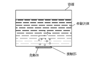
- FIG. 2 shows a conventional pool boiling cooler.
- the cooler includes a container and a working fluid contained in the container, and the container has a contact portion with a heating element to be cooled.
- the working fluid existing in the vicinity of the contact portion boils.
- steam is generated by boiling, working fluid is supplied to the contact portion due to the density difference between the gas and liquid. In this way, the newly supplied working fluid is further evaporated, and heat is removed from the heating element.
- the pool boiling type cooler is advantageous in terms of compactness and energy saving because it does not require an external power source for circulating the liquid as in the forced flow boiling method.
- the limit heat flux of the cooler by the conventional pool boiling method is about 1000 kW / m 2 in the saturated state under atmospheric pressure and water conditions (see Non-Patent Document 1).
- a limit heat flux of at least about 2000 kW / m 2 is required for the cooler.
- Patent Document 1 JP 2009-139005 A (Patent Document 1) that a porous body is provided between a heating element and water in a cooling container, and water is supplied by capillary action of the porous body.
- the conventional limit heat flux is drastically improved with a simple structure by supplying the heat generating element and discharging the generated steam into the water in the container.
- An object of the present invention is to provide a cooler having a simple structure and stably having a good cooling effect, a cooling device using the cooler, and a method for cooling a heating element.
- the porous body disclosed in Patent Document 1 is provided on the heating element side to form the first porous body, and is further overlapped with the working fluid. It has been found that a cooler with a further improved cooling effect can be provided by providing the second porous body having a higher transmittance than the first porous body on the side.
- an aspect of the present invention is a boiling-type cooler for cooling a heating element, and a container that contains a working fluid, and is in contact with the working fluid in the container and faces the heating element.
- a cooling member provided so as to include a first porous body provided on the heating element side and a second porous body provided on the working fluid side.
- the first porous body has a laminated structure, and the first porous body has a first working fluid supply section that supplies the working fluid to a contact section with the heating element by capillary action, and vapor generated at the contact section.
- a first vapor discharge section that discharges to the second porous body side, and the second porous body includes a second working fluid supply section that supplies the working fluid to the first porous body.
- the second porous body may have a pore radius larger than that of the first porous body and / or a porosity of the first porous body.
- the permeability of the working fluid is made larger than that of the first porous body.
- each of the first porous body and the second porous body is composed of an aggregate of porous particles.
- both the first porous body and the second porous body are formed of a porous layer.
- either one of the first porous body and the second porous body is composed of an aggregate of porous particles, and the other is porous. It is composed of a quality layer.
- the first porous body is composed of an aggregate of porous nanoparticles
- the second porous body has a mesh structure. Consists of layers.
- the first porous body is formed of a porous layer, and the first vapor discharge portion is a hole penetrating the porous layer. is there.
- a gap region is formed at a contact portion between the first porous body and the heating element.
- the second porous body is made of metal.
- the end of the second porous body formed of the metal is fixed to the heating element by welding.
- a heat radiating fin is welded to the heating element, and the second porous body is fixed to the heat radiating fin by welding.
- Another aspect of the present invention is a cooling device including the cooler according to the present invention and a condenser that is connected to a container of the cooler and liquefies the evaporated working fluid.
- a cooling method using a boiling system in which the heating element is cooled by at least partially immersing the heating element in a working fluid of a container containing the working fluid.
- a cooling member configured in a laminated structure including a first porous body provided on the heating element side and a second porous body provided on the working fluid side on the surface of the portion immersed in The first porous body includes a first working fluid supply unit that supplies the working fluid to a contact portion with the heating element by capillary action, and vapor generated at the contact portion.
- a first vapor discharge section for discharging to the porous body side, and the second porous body includes a second working fluid supply section for supplying the working fluid to the first porous body, and the first porous body.
- a nanoparticle is dispersed in the working fluid, and a porous surface having a mesh structure is formed on the surface of the part immersed in the working liquid of the heating element.
- the second porous body composed of a porous layer is provided, and the nanoparticles in the working fluid are deposited on the heat transfer surface of the heating fluid by the heat from the heating body, and the porous nanoparticles are deposited.
- the cooler of the present invention, the cooling device using the same, and the heating element cooling method have at least the following effects: (1) A critical heat flux of about 2000 kW / m 2 necessary to prevent melt-through at the bottom of the reactor pressure vessel, and more than about 2500 kW / m 2 can be realized. (2) When steam is generated in the working fluid supply section and the contact section of the first porous body, liquid is forcibly supplied to the contact section by capillary action.
- the container (water tank) for storing the working fluid does not need to be provided with a water flow path or a pump, can use a simple water reservoir, can have a simple structure, and is low in installation cost and running cost. .
- the thickness of the porous body provided at the contact portion with the heating element is preferably thin from the viewpoint of the capillary limit mechanism, but if it is too thin, the porous body is porous while the coalescing bubbles stay on the upper part of the porous body. Liquid drainage easily occurs inside the body, and the critical heat flux is reduced. Therefore, in the present invention, the porous body provided at the contact portion with the heating element is the first porous body, and the working fluid permeability is higher on the porous body (on the working fluid side) than the first porous body. A second porous body is provided. According to such a configuration, the second porous body that supplies the working fluid to the first porous body in an abundant manner between the first porous body and the vapor mass above the first porous body. Therefore, even if the thickness of the first porous body is reduced, the occurrence of liquid withering is suppressed, and the critical heat flux can be prevented from being reduced.
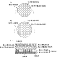
- FIG. (A) is a plan view of the first porous body
- (B) is a plan view of the second porous body
- (C) is 5-5 in a state where the cooling member is provided in the contact portion.
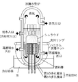
- FIG. 6 is a schematic diagram of a cooler at the bottom of a reactor pressure vessel of a light water reactor according to Embodiment 2.
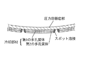
- FIG. 1 It is the schematic diagram of embodiment with which the 2nd porous body was fixed to the reactor pressure vessel bottom part which is a heat generating body by the edge part by welding.
- A is a schematic diagram of a form in which each of the first porous body and the second porous body is composed of an aggregate of porous particles
- B is a diagram illustrating the first porous body and the second porous body.
- 2 is a schematic diagram of a form in which each of the two porous bodies is composed of a porous layer
- (C) is a set of porous particles in which one of the first porous body and the second porous body is formed. It is a schematic diagram of the form comprised by the body and the other is comprised by the porous layer.
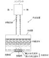
- FIG. 2 is a schematic diagram of an experimental apparatus used in Test Examples 1 and 2.
- FIG. 2 is a boiling curve obtained in Test Example 1.
- 3 is a boiling curve obtained in Test Example 2.
- the first porous body is composed of an aggregate of porous nanoparticles
- the second porous body is composed of a porous layer having a mesh structure. is there.
- A) is a heat transfer surface observation photograph after polishing of the heat transfer surface produced in Test Example 3.
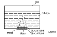
- FIG. 4 shows a cooler using a pool boiling method according to the first embodiment.
- the cooler includes a container for storing the working fluid, and a cooling member provided in the container so as to be in contact with the working fluid and to be in contact with the heating element.
- the cooling member has a laminated structure of a first porous body provided on the heating element side and a second porous body provided on the working fluid side.
- FIG. 5 shows a cooling member according to this embodiment.
- 5A is a plan view of the first porous body
- FIG. 5B is a plan view of the second porous body
- FIG. 5C is a cooling member provided at the contact portion.
- the first porous body includes a first working fluid supply unit and a first vapor discharge unit.
- the first working fluid supply unit supplies the working fluid to the contact portion with the heating element by capillary action.
- the first steam discharge unit discharges the steam generated by the heat from the heating element from the contact portion to the second porous body side.
- the first porous body is composed of a porous layer, and has, for example, a mesh structure having a large number of rectangular holes, and a lattice-like porous layer around the rectangular holes.
- the first vapor discharge in which the portion functions as a first working fluid supply unit that supplies the working fluid to the contact portion by capillary action, and the rectangular hole discharges the steam generated at the contact portion to the second porous body side It functions as a part.
- the supply of the working fluid and the discharge of the steam are performed using separate paths in this manner, so that the steam covers the contact portion and the limit heat flux is limited. Can be suppressed. Further, as shown in FIG.
- the second porous body is composed of a porous layer, for example, a mesh structure having a large number of rectangular holes, like the first porous body.
- the lattice-shaped porous layer portion around the rectangular hole functions as a second working fluid supply unit that supplies the working fluid to the first porous body, and the rectangular hole is the first hole. It functions as a second vapor discharge unit that discharges the vapor discharged from the porous body into the working fluid.
- the second porous body has a larger working fluid permeability than the first porous body, has a function of holding the working fluid, and coalesced bubbles stay in the upper portion of the second porous body. In the meantime, it functions so that the working fluid is quickly supplied to the first porous body.
- the second porous body operates more than the permeability of the first porous body by making the pore radius of the porous body larger than the pore radius of the first porous body to facilitate the passage of the working fluid.
- the fluid permeability can be increased.
- the pore radius of the porous body may be a radius of a hole originally provided in each porous body, or may be a radius of a hole formed in each porous body.
- the shape of the pores of the porous body can be various shapes such as a polygonal shape, a circular shape, and an elliptical shape. The radius of the circumscribed circle at.
- the second porous body has a porosity of the porous body larger than that of the first porous body to facilitate the passage of the working fluid, so that the permeability of the first porous body is higher than that of the first porous body.
- the permeability of the working fluid can be increased.
- the porosity of the porous body can be increased, for example, by adjusting the particle size / amount of the binder to be mixed with the metal powder in the manufacturing process of the porous body.
- the working fluid can be a liquid having a surface tension such as water, a low-temperature fluid, a refrigerant, an organic solvent, or the like.
- the size of the hole for releasing the vapor generated at the contact portion into water is preferably small. It can be set to 2000 ⁇ m.
- the gap between the holes for releasing the steam generated at the contact portion into the water is preferably small, and can be, for example, 100 to 1000 ⁇ m. .
- the porous material constituting the first working fluid supply unit in the first porous body may be ceramics such as cordierite or a sintered metal, for example.
- the first porous body supplies the working fluid to the contact portion by capillary action when the liquid evaporates in the first working fluid supply portion, but considering the limit mechanism of liquid supply by capillary force, As the capillary length (ie, the thickness of the first porous body) is thinner, the limit, that is, the “critical heat flux” can be increased.
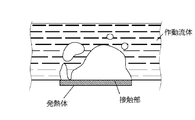
- FIG. 3 shows a state in which the vapor mass is formed on the contact portion under the high heat flux condition, but the volume of the vapor mass increases with time and eventually cuts off from the contact portion.
- a liquid film having a finite thickness exists between the vapor mass and the contact portion (that is, the bottom of the vapor mass).
- a macro liquid film exists between the vapor mass and the contact portion (that is, the bottom of the vapor mass).
- burnout occurs when the macro liquid film at the bottom of the vapor mass is exhausted and exhausted while the vapor mass remains on the macro liquid film.
- the heat flux at this time is called “limit heat flux”.
- the thickness of the first porous body is preferably thinner from the limit mechanism of liquid supply by capillary force (capillary limit mechanism), but if the thickness is too thin and is approximately the same as the thickness of the macro liquid film, Liquid withering tends to occur near the contact portion of the porous body, and the critical heat flux becomes small.
- the thickness of the porous body provided in the contact portion with the heating element is preferably thin from the viewpoint of the capillary limit mechanism, but if it is thinner than the macro liquid film thickness, the liquid body is liable to wither inside the porous body. There is a problem that the critical heat flux becomes small. Therefore, in the present invention, the porous body provided at the contact portion with the heating element is the first porous body, and the permeability of the working fluid is higher than that of the first porous body (on the working fluid side). A large second porous body is provided. According to such a configuration, the second porous body that supplies the working fluid to the first porous body in an abundant manner between the first porous body and the vapor mass above the first porous body.
- the thickness of the first porous body is reduced, the occurrence of liquid withering is suppressed, and the critical heat flux can be prevented from being reduced.
- the thickness of the second porous body is preferably about 1 to 2 mm or more.
- the second porous body may be formed of ceramics such as cordierite, but is preferably formed of metal from the viewpoint of workability and strength.
- FIG. 5 shows a form in which the first porous body and the second porous body are both circular, and the first and second vapor discharge portions are both lattice-shaped. There is no intention to limit to such a form.
- the first and second vapor discharge portions may be formed in a honeycomb shape, for example.
- FIG. 5 shows the first and second working fluid supply sections and the steam discharge section so as to be orthogonal to the lower contact section and the upper working fluid side. If the section and the steam discharge section respectively provide paths between the surface in contact with the contact section and the surface in contact with the working fluid, they are configured so as to be, for example, a curved path or a bent path, without being orthogonal to each other. May be.
- the rectangular holes of each porous body function as a vapor discharge part, but the shape of the holes is not particularly limited, and other polygonal shapes, circular shapes, oval shapes It may be a shape or the like. Further, the holes may be holes originally provided in each porous body, or may be holes formed in each porous body.
- first porous body and the second porous body is not particularly limited.
- first porous body and the second porous body are both aggregates of porous particles. It may be configured.
- both the 1st porous body and the 2nd porous body may be comprised by the porous layer.
- one of the first porous body and the second porous body may be composed of an aggregate of porous particles, and the other may be composed of a porous layer.
- first porous body and the second porous body are composed of an aggregate of porous particles
- a gap between a plurality of porous particles has a function as a vapor discharge portion, and the gap It is possible to adopt a configuration in which the members around are functioning as a working fluid supply unit.
- the laminated structure of the cooling member is not limited to the one constituted by the first porous body and the second porous body, and the third porous body is further provided on the working fluid side of the second porous body.
- a material body may be provided to form a three-layer structure as a whole.
- the third porous body includes a working fluid supply section that supplies the working fluid to the second porous body, and a steam discharge section that discharges the steam discharged from the second porous body into the working fluid.
- the laminated structure of the cooling member may be configured to have a total of four or more layers by laminating a plurality of porous bodies on the working fluid side of the second porous body.
- a gap region is formed at the contact portion between the first porous body of the cooling member and the heating element.
- the vapor generated on the bottom surface of the first working fluid supply unit of the first porous body proceeds along the bottom surface of the first working fluid supply unit, and then exits to the first vapor discharge unit. It is discharged upward from the steam discharge section.
- the gap region becomes a passage for the vapor generated on the bottom surface of the first porous body, Steam discharge is promoted, and the critical heat flux is improved.
- the gap area may be processed with a rough rough surface, but the gap area necessary for steam discharge is very small, so that the first porous body is simply brought into contact with the contact part.
- a sufficient gap region is formed by the roughness of the surface of the contact portion that is provided from the beginning.
- region is lose
- the entire heating element can be immersed in the working fluid, or a part of the heating element can be partially immersed from the liquid level of the working fluid for cooling.
- the heating element takes various forms depending on cases such as a floating state, a state where it is placed on the bottom surface of the container, and the main point is that the first porous body and the second porous body are immersed in the working fluid.
- the liquid when steam is generated in the working fluid supply section and the contact section of the first porous body, the liquid is forcibly supplied to the contact section by capillary action, so that the container for storing the working fluid such as water is stored.
- the porous body provided at the contact portion with the heating element is the first porous body, and the working fluid permeability is higher on the porous body (on the working fluid side) than the first porous body.
- a second porous body is provided.
- FIG. 6 the schematic diagram of the cooler of the reactor pressure vessel bottom part of the light water reactor which concerns on Embodiment 2 is shown.
- a support ring is attached so as to surround the reactor in the circumferential direction from the side of the reactor, and a honeycomb mounting net (metal mesh) supported by the support ring is attached.
- the honeycomb mounting net may not be made of metal but may be formed of a heat resistant resin.
- a cooling member having a laminated structure of the honeycomb-like first porous body and the second porous body is provided so as to cover the bottom of the reactor pressure vessel. Temporarily fix.
- the honeycomb mounting net is pulled near the support ring to bring the honeycomb mounting net into contact with the bottom of the reactor pressure vessel.
- the cooling member is structured to be held from below by the honeycomb mounting net.
- the honeycomb mounting net may not be a mesh, and may be formed using a plurality of tapes because the construction is simpler. Moreover, a part including the deepest part of the reactor pressure vessel bottom is immersed in a vessel containing water.
- the first porous body and the second porous body of the cooling member have the same structure as in the first embodiment, so as to realize a good critical heat flux and prevent melt-through at the bottom of the reactor pressure vessel. It is possible to realize a critical heat flux of about 2000 kW / m 2 required for the process, and about 2500 kW / m 2 or more beyond that.
- the cooler according to the present invention is particularly suitable for cooling the bottom of the reactor pressure vessel in the event of a reactor accident.
- the cooling member covers a part of the bottom of the reactor pressure vessel.
- the cooling member may be provided so as to cover all of the portion immersed in the vessel containing water at the bottom of the reactor pressure vessel. Good.
- the cooling member provided with the honeycomb-shaped first porous body and the second porous body so as to cover the bottom of the reactor pressure vessel of the second embodiment may be supported without using the honeycomb mounting net.
- the first and second porous bodies are formed by forming the second porous body from metal and fixing its end to the bottom of the reactor pressure vessel, which is a heating element, by welding. May be supported. Welding is preferably spot welding because it is easy to work and provides sufficient support.
- the radiation fin is welded to the heat generating body, and the second porous body may be fixed to the radiation fin by welding. According to such a configuration, the heat from the heat generating element is released from the heat radiation fin, so that the heat generating element can be cooled more favorably.
- both the first porous body and the second porous body may be composed of aggregates of porous particles.
- both the first porous body and the second porous body may be composed of a porous layer.
- either one of the first porous body and the second porous body is composed of an aggregate of porous particles, and the other is composed of a porous layer. May be.
- the porous body is composed of an aggregate of porous particles, the aggregate of porous particles is wrapped with a fine mesh material to such an extent that the particles cannot pass through.
- the said mesh material For example, it can form with the honeycomb mounting
- FIG. 9 shows a cooling device according to the third embodiment.
- the cooling device includes the cooler according to the first embodiment and a capacitor connected to the container. In the condenser, the evaporated working fluid is liquefied and returned to the container.
- the cooling device does not require an external power source such as a pump, and is excellent in compactness and energy saving as the entire device.
- FIG. 10 shows a modification of the cooling device according to the third embodiment. 9 and 10 can be used together with the cooler of the second embodiment.
- the first porous body constituting the cooling member to the second porous body are changed from a porous body having a smaller pore diameter to a porous body having a gradually larger pore diameter.
- the porous body on the side in direct contact with the bulk liquid is preferably formed so that the pore diameter is different from the diameter of fine particles such as dust existing in a large amount of working fluid such as water.
- the porous body on the side in direct contact with the bulk liquid has a pore diameter sufficiently larger or smaller than the diameter of the fine particles.
- a porous body having a large pore diameter is gradually laminated from a porous body having a small pore diameter, and the outermost pore diameter of the porous body is set to be a working fluid. If the particle size of the dust inside is sufficiently larger or smaller than that, the dust particles that have flowed in do not immediately penetrate into the deep part of the porous body, but are formed immediately after entering the porous body.
- FIG. 14 shows a cooling device according to the fifth embodiment.
- the first porous body may be composed of an aggregate of porous nanoparticles
- the second porous body may be composed of a porous layer having a mesh structure.
- FIG. 14A is a plan view of a second porous body composed of a mesh-structured porous layer having a large number of rectangular holes
- FIG. 14B is a cooling member provided at the contact portion.
- the first porous body is composed of an aggregate of nanoparticles having an average particle diameter of 10 to 50 nm. Examples of the nanoparticles that can be used include metals, alloys, oxides, nitrides, carbides, and carbon.
- an aqueous solution in which nanoparticles are diffused is provided by a predetermined means on the heat transfer surface where the first porous body is to be formed, and the state While heating, boil by heating on the heat transfer surface.
- the porous nanoparticles are deposited on the boiling heat transfer surface to form an aggregate, which becomes the first porous body.
- the 2nd porous body comprised by the porous layer which has a mesh structure is provided on the aggregate
- a second porous body is provided on the surface of the heating element, and then the first porous body is provided between the surface of the heating element and the second porous body.
- a body may be provided.
- the second is configured by a porous layer having a mesh structure on the surface of a part immersed in the working liquid of the heating element in which nanoparticles are dispersed in the working fluid.
- the porous body is provided, and the nano particles in the working fluid are precipitated on the heat transfer surface of the heating element by the heat from the heating element to form an aggregate of the porous nanoparticles.
- the cooling member is attached to the surface of the portion of the heating element that is immersed in the working liquid.
- a honeycomb porous body (second porous body) is provided in advance in a pressure vessel of a nuclear reactor, and nanoparticles are supplied and dispersed in the working fluid when an accident occurs. Subsequently, the working fluid containing the nanoparticles boiled on the working fluid side surface (heat transfer surface) of the pressure vessel, so that a set of porous nanoparticles is formed between the heat transfer surface and the second porous body.
- a first porous body composed of the body is formed.
- the aggregate of nanoparticles constituting the first porous body has a large number of pores between or within the particles constituting the first working fluid supply section or the first vapor discharge section.
- the first porous body performs the supply of the working fluid and the discharge of the steam using separate paths, so that the steam covers the contact portion as described with reference to FIG. The occurrence of the problem that the critical heat flux is limited can be suppressed.
- the second porous body functions as a second working fluid supply section in which the lattice-shaped porous layer portion around the rectangular holes supplies the working fluid to the first porous body.
- the holes function as a second vapor discharge unit that discharges the vapor discharged from the first porous body into the working fluid.
- the second porous body has a larger working fluid permeability than the first porous body, has a function of holding the working fluid, and coalesced bubbles stay in the upper portion of the second porous body. In the meantime, it functions so that the working fluid is quickly supplied to the first porous body.
- the first porous body is composed of an aggregate of porous nanoparticles, the wettability of the heat transfer surface is improved, and the second porous layer having a mesh structure is used. By using this porous body, the supply performance of the working fluid to the heat transfer surface becomes better. Thereby, it becomes difficult to produce the dry area
- the present invention can be applied to various electronic devices and other thermal devices having a high heat generation density in addition to cooling of the reactor pressure vessel.
- divertor cooling in fusion reactors high performance of capillary pump loops, semiconductor lasers, data center server cooling, CFC-cooled chopper control devices, power electronics, and the like are conceivable.
- it can be applied to a water-cooled jacket that improves the high-temperature working environment by reducing heat dissipated from the side or bottom of a glass or aluminum melting furnace to the surrounding environment.
- the present invention can be applied to a water-cooled jacket installed on the side of the fire wall or the bottom of the fire wall to reduce damage by cooling the fire wall such as a large garbage incinerator from the outside.
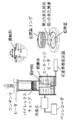
- FIG. 11 shows a schematic diagram of the experimental apparatus.
- the diameter of the contact portion in contact with the working fluid was 30 mm.
- a copper cylinder embedded with a cartridge heater was used as a heating element.
- the amount of heating was controlled by controlling the voltage applied to the cartridge heater with a variable autotransformer.
- the heat flux was calculated from the distance and the thermal conductivity by the Fourier equation.
- the container was a Pyrex (registered trademark) tube having an inner diameter of 87 mm and an outer diameter of 100 mm so that the state of internal boiling could be observed.
- the working liquid was distilled water at a depth of 60 mm and heated with a heater to maintain the saturation temperature.
- the generated steam was condensed by a condenser provided at the upper end of the Pyrex (registered trademark) tube and returned to the container.
- the first porous body of the cooling member a disk (trade name: MF-Millipore) having a mixture of cellulose acetate and cellulose nitrate was used.
- the diameter of the disc of the first porous body was 30 mm, the hole radius was 0.8 ⁇ m, the porosity was 80%, and the plate thickness was 0.15 mm.
- a porous disk of a SUS plate SUS316L was used as the second porous body of the cooling member.
- the diameter of the disk of the second porous body is 30 mm, the hole radius is 10 ⁇ m, the porosity is 70%, the plate thickness is 1 mm, and the transmittance of the second porous body is 10 of that of the first porous body. It was about twice.
- the second porous body was placed on the first porous body having such a configuration to form a cooling member.
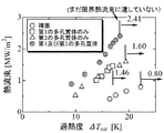
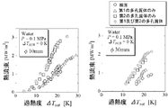
- FIG. 12 shows the boiling curve obtained in the experiment.
- the boiling curve represents the characteristics of boiling heat transfer, and the vertical axis represents the heat flux, and the horizontal axis represents the difference between the heating element temperature and the liquid saturation temperature, that is, the degree of superheat ⁇ Tsat [K] at the contact portion.
- the arrow in the figure indicates the burnout occurrence point where the cooling capacity is significantly deteriorated and the temperature of the contact portion rapidly rises, and the value [MW / m 2 ] of the critical heat flux at that time is shown in the figure.
- the limit heat flux was 0.8 MW / m 2 , but in the case where only the first porous body is installed in the contact portion, the limit The heat flux was 1.46 MW / m 2 , an improvement over the bare surface.
- the first and second porous bodies were installed, the heat could be stably removed even when the critical heat flux was 2.41 MW / m 2 .
- 2.41 MW / m 2 shown in FIG. 12 is not yet the critical heat flux value. From FIG.
- Test Example 2 Subsequently, in order to examine the relationship between the surface roughness of the contact portion surface (heat transfer surface) and the critical heat flux, the experimental apparatus, the first porous body, and the second porous body of Test Example 1 were used. The test was conducted. First, the surface of the contact portion in contact with the working fluid of the experimental apparatus of Test Example 1 is polished with sandpaper (# 40), and the first porous body and the second porous body are provided on the surface in this order. It was set as the cooling member. Further, the surface of the contact portion in contact with the working fluid of the experimental apparatus of Test Example 1 is polished with sandpaper (# 80), and the first porous body and the second porous body are provided in this order on the surface. It was set as the cooling member. Furthermore, without polishing the surface of the contact portion in contact with the working fluid of the experimental apparatus of Test Example 1, a first porous body is provided via an adhesive, and a second porous body is further provided thereon for cooling. It was set as a member.
- FIG. 13 shows the boiling curve obtained at this time. From FIG. 13, the surface roughness of the surface of the contact portion (heat transfer surface) was the roughest, and the critical heat flux of the cooling member tested by polishing the surface of the contact member with sandpaper (# 40) was the best.
- Test Example 3 In order to evaluate the critical heat flux related to the cooling member shown in the fifth embodiment using the same type of apparatus as the experimental apparatus shown in FIG. 11, the following tests were performed.
- the diameter of the contact portion in contact with the working fluid was 30 mm and 10 mm.
- a copper cylinder embedded with a cartridge heater was used as a heating element. The amount of heating was controlled by controlling the voltage applied to the cartridge heater with a variable autotransformer.
- the heat flux was calculated from the distance and the thermal conductivity by the Fourier equation.
- the container was a Pyrex (registered trademark) tube having an inner diameter of 87 mm and an outer diameter of 100 mm so that the state of internal boiling could be observed.
- the working liquid was distilled water at a depth of 60 mm and heated with a heater to maintain the saturation temperature.
- the generated steam was condensed by a condenser provided at the upper end of the Pyrex (registered trademark) tube and returned to the container.
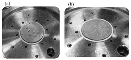
- an aggregate of porous nanoparticles was produced as follows. That is, first, in a beaker containing distilled water prepared in advance, titanium dioxide (average particle size 21 nm) weighed with an electronic balance was placed as nanoparticles and dispersed. At this time, the nanoparticle (titanium dioxide) concentration was 0.04 g / L. Next, the heat transfer surface shown in FIG. 11 was provided in the container to supply distilled water, and the water in the container was boiled. The heat transfer surface was polished in advance.
- FIG. 15A shows a heat transfer surface observation photograph after the heat transfer surface polishing.
- FIG. 15B shows a heat transfer surface observation photograph after the nanoparticle coating of the heat transfer surface.
- a porous disk (SUS316L) of a SUS plate was used as a second porous body (porous layer having a mesh structure) of the cooling member.
- the diameter of the disk of the 2nd porous body prepared the thing of 30 mm, and the thing of 10 mm. In all cases, the hole radius was 10 ⁇ m, the porosity was 70%, and the plate thickness was 1 mm.
- the second porous body (porous layer having a mesh structure) having such a configuration was placed on the first porous body (aggregate of porous nanoparticles) to form a cooling member.
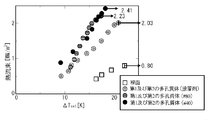
- FIG. 16 shows a boiling curve obtained in the experiment.
- the critical heat flux was 1.4 MW / m 2 (heat transfer surface ⁇ 10 mm), 0.9 MW / m 2 (heat transfer surface ⁇ 30 mm).
- the first porous body when installed in only the contact portion is critical heat flux is 2.0 mW / m 2 (heat transfer surface .phi.10 mm), 1.2 MW / m 2 (Heat transfer surface ⁇ 30 mm), which is improved over the bare surface.
- the critical heat flux is 3.1 MW / m 2.
- the heat could be removed stably even at (heat transfer surface ⁇ 10 mm) and 2.2 MW / m 2 (heat transfer surface ⁇ 30 mm). Since this time the heater before the state of the critical heat flux is damaged, 3.1 mW / m 2 as shown in FIG. 16 (heat transfer surface ⁇ 10mm), 2.2MW / m 2 (heat transfer surface .phi.30 mm) is It is not yet the value of critical heat flux.
Landscapes
- Engineering & Computer Science (AREA)
- Physics & Mathematics (AREA)
- General Engineering & Computer Science (AREA)
- Plasma & Fusion (AREA)
- High Energy & Nuclear Physics (AREA)
- Thermal Sciences (AREA)
- Mechanical Engineering (AREA)
- Crystallography & Structural Chemistry (AREA)
- Chemical & Material Sciences (AREA)
- Life Sciences & Earth Sciences (AREA)
- Sustainable Development (AREA)
- Structure Of Emergency Protection For Nuclear Reactors (AREA)
- Cooling Or The Like Of Semiconductors Or Solid State Devices (AREA)
Priority Applications (3)
| Application Number | Priority Date | Filing Date | Title |
|---|---|---|---|
| US14/777,700 US20160273839A1 (en) | 2013-03-18 | 2014-02-06 | Cooler, cooling apparatus using the same, and method for cooling heat generation element |
| EP14767940.1A EP2977700B1 (en) | 2013-03-18 | 2014-02-06 | Cooler, cooling device using same, and method for cooling heat generation element |
| US15/959,766 US20180299207A1 (en) | 2013-03-18 | 2018-04-23 | Cooler, cooling apparatus using the same, and method for cooling heat generation element |
Applications Claiming Priority (4)
| Application Number | Priority Date | Filing Date | Title |
|---|---|---|---|
| JP2013055533 | 2013-03-18 | ||
| JP2013-055533 | 2013-03-18 | ||
| JP2013-262872 | 2013-12-19 | ||
| JP2013262872A JP5882292B2 (ja) | 2013-03-18 | 2013-12-19 | 冷却器及びそれを用いた冷却装置、並びに、発熱体の冷却方法 |
Related Child Applications (2)
| Application Number | Title | Priority Date | Filing Date |
|---|---|---|---|
| US14/777,700 A-371-Of-International US20160273839A1 (en) | 2013-03-18 | 2014-02-06 | Cooler, cooling apparatus using the same, and method for cooling heat generation element |
| US15/959,766 Division US20180299207A1 (en) | 2013-03-18 | 2018-04-23 | Cooler, cooling apparatus using the same, and method for cooling heat generation element |
Publications (1)
| Publication Number | Publication Date |
|---|---|
| WO2014148137A1 true WO2014148137A1 (ja) | 2014-09-25 |
Family
ID=51579832
Family Applications (1)
| Application Number | Title | Priority Date | Filing Date |
|---|---|---|---|
| PCT/JP2014/052783 Ceased WO2014148137A1 (ja) | 2013-03-18 | 2014-02-06 | 冷却器及びそれを用いた冷却装置、並びに、発熱体の冷却方法 |
Country Status (4)
| Country | Link |
|---|---|
| US (2) | US20160273839A1 (enExample) |
| EP (1) | EP2977700B1 (enExample) |
| JP (1) | JP5882292B2 (enExample) |
| WO (1) | WO2014148137A1 (enExample) |
Cited By (3)
| Publication number | Priority date | Publication date | Assignee | Title |
|---|---|---|---|---|
| WO2015174423A1 (ja) * | 2014-05-12 | 2015-11-19 | 国立大学法人横浜国立大学 | 冷却器及びそれを用いた冷却装置、並びに、発熱体の冷却方法 |
| WO2016051569A1 (ja) * | 2014-10-02 | 2016-04-07 | 富士通株式会社 | 蒸発器、冷却装置及び電子装置 |
| WO2025150329A1 (ja) * | 2024-01-10 | 2025-07-17 | 国立研究開発法人産業技術総合研究所 | 伝熱構造体 |
Families Citing this family (4)
| Publication number | Priority date | Publication date | Assignee | Title |
|---|---|---|---|---|
| JP2016040505A (ja) * | 2014-08-12 | 2016-03-24 | 国立大学法人横浜国立大学 | 冷却器及びそれを用いた冷却装置、並びに、発熱体の冷却方法 |
| JP2016217684A (ja) * | 2015-05-26 | 2016-12-22 | 国立大学法人横浜国立大学 | 冷却器及びそれを用いた冷却装置、並びに、発熱体の冷却方法 |
| JP6756470B2 (ja) * | 2015-10-05 | 2020-09-16 | 三菱重工業株式会社 | 原子炉および原子力プラント |
| CN111512110A (zh) * | 2017-11-06 | 2020-08-07 | 祖达科尔有限公司 | 热交换的系统及方法 |
Citations (10)
| Publication number | Priority date | Publication date | Assignee | Title |
|---|---|---|---|---|
| JP2000049266A (ja) * | 1998-05-25 | 2000-02-18 | Denso Corp | 沸騰冷却装置 |
| US20050280996A1 (en) * | 2004-06-16 | 2005-12-22 | Hakan Erturk | Heat dissipating device with enhanced boiling/condensation structure |
| US20070240855A1 (en) * | 2006-04-14 | 2007-10-18 | Foxconn Technology Co., Ltd. | Heat pipe with composite capillary wick structure |
| JP2008039378A (ja) * | 2006-07-14 | 2008-02-21 | Central Glass Co Ltd | ヒートパイプ |
| JP2009139005A (ja) | 2007-12-05 | 2009-06-25 | Yokohama National Univ | 冷却器及びその冷却器を備える冷却装置 |
| JP2009250810A (ja) * | 2008-04-07 | 2009-10-29 | Seiko Epson Corp | 電子部品の温度制御装置およびハンドラ装置 |
| JP2010151354A (ja) * | 2008-12-24 | 2010-07-08 | Sony Corp | 熱輸送デバイス及び電子機器 |
| JP2012032276A (ja) * | 2010-07-30 | 2012-02-16 | Toshiba Corp | 炉心溶融物冷却装置および格納容器 |
| JP2012043954A (ja) * | 2010-08-18 | 2012-03-01 | Fujitsu Ltd | 半導体装置 |
| JP2013243249A (ja) * | 2012-05-21 | 2013-12-05 | Denso Corp | 沸騰冷却用伝熱面および沸騰冷却装置 |
Family Cites Families (14)
| Publication number | Priority date | Publication date | Assignee | Title |
|---|---|---|---|---|
| US7051793B1 (en) * | 1998-04-20 | 2006-05-30 | Jurgen Schulz-Harder | Cooler for electrical components |
| US6227287B1 (en) * | 1998-05-25 | 2001-05-08 | Denso Corporation | Cooling apparatus by boiling and cooling refrigerant |
| US6994152B2 (en) * | 2003-06-26 | 2006-02-07 | Thermal Corp. | Brazed wick for a heat transfer device |
| CN100437006C (zh) * | 2005-08-12 | 2008-11-26 | 富准精密工业(深圳)有限公司 | 热管之制造方法 |
| FR2896614B1 (fr) * | 2006-01-25 | 2010-10-15 | Commissariat Energie Atomique | Procede et dispositif de fermeture en piscine d'un etui charge avec du combustible nucleaire irradie |
| EP1991824B1 (en) * | 2006-03-03 | 2019-11-06 | Micro Delta T AB | Method for forming a surface layer on a substrate |
| US8561673B2 (en) * | 2006-09-26 | 2013-10-22 | Olantra Fund X L.L.C. | Sealed self-contained fluidic cooling device |
| US9920530B2 (en) * | 2007-04-17 | 2018-03-20 | University Of Virginia Patent Foundation | Heat-managing composite structures |
| EP2009146A1 (en) * | 2007-06-22 | 2008-12-31 | Danmarks Tekniske Universitet - DTU | A microporous coating or structure and a process for producing it |
| US8170173B2 (en) * | 2007-11-15 | 2012-05-01 | The State Of Oregon Acting By And Through The State Board Of Higher Education On Behalf Of Oregon State University | Passive emergency feedwater system |
| US7832462B2 (en) * | 2008-03-31 | 2010-11-16 | Alcatel-Lucent Usa Inc. | Thermal energy transfer device |
| US8235096B1 (en) * | 2009-04-07 | 2012-08-07 | University Of Central Florida Research Foundation, Inc. | Hydrophilic particle enhanced phase change-based heat exchange |
| TW201127266A (en) * | 2010-01-20 | 2011-08-01 | Pegatron Corp | Vapor chamber and manufacturing method thereof |
| DE102011011688A1 (de) * | 2011-02-18 | 2012-08-23 | Fraunhofer-Gesellschaft zur Förderung der angewandten Forschung e.V. | Verfahren zur Beschichtung einer Wärmetauscherstruktur, beschichtete Wärmetauscherstruktur und deren Verwendung |
-
2013
- 2013-12-19 JP JP2013262872A patent/JP5882292B2/ja active Active
-
2014
- 2014-02-06 WO PCT/JP2014/052783 patent/WO2014148137A1/ja not_active Ceased
- 2014-02-06 US US14/777,700 patent/US20160273839A1/en not_active Abandoned
- 2014-02-06 EP EP14767940.1A patent/EP2977700B1/en active Active
-
2018
- 2018-04-23 US US15/959,766 patent/US20180299207A1/en not_active Abandoned
Patent Citations (10)
| Publication number | Priority date | Publication date | Assignee | Title |
|---|---|---|---|---|
| JP2000049266A (ja) * | 1998-05-25 | 2000-02-18 | Denso Corp | 沸騰冷却装置 |
| US20050280996A1 (en) * | 2004-06-16 | 2005-12-22 | Hakan Erturk | Heat dissipating device with enhanced boiling/condensation structure |
| US20070240855A1 (en) * | 2006-04-14 | 2007-10-18 | Foxconn Technology Co., Ltd. | Heat pipe with composite capillary wick structure |
| JP2008039378A (ja) * | 2006-07-14 | 2008-02-21 | Central Glass Co Ltd | ヒートパイプ |
| JP2009139005A (ja) | 2007-12-05 | 2009-06-25 | Yokohama National Univ | 冷却器及びその冷却器を備える冷却装置 |
| JP2009250810A (ja) * | 2008-04-07 | 2009-10-29 | Seiko Epson Corp | 電子部品の温度制御装置およびハンドラ装置 |
| JP2010151354A (ja) * | 2008-12-24 | 2010-07-08 | Sony Corp | 熱輸送デバイス及び電子機器 |
| JP2012032276A (ja) * | 2010-07-30 | 2012-02-16 | Toshiba Corp | 炉心溶融物冷却装置および格納容器 |
| JP2012043954A (ja) * | 2010-08-18 | 2012-03-01 | Fujitsu Ltd | 半導体装置 |
| JP2013243249A (ja) * | 2012-05-21 | 2013-12-05 | Denso Corp | 沸騰冷却用伝熱面および沸騰冷却装置 |
Non-Patent Citations (2)
| Title |
|---|
| S. G. KANDLIKAR; M. SHOJI; V. K. DHIR: "Handbook of Phase Change: Boiling and Condensation", 1999, TAYLOR FRANCIS |
| See also references of EP2977700A4 |
Cited By (5)
| Publication number | Priority date | Publication date | Assignee | Title |
|---|---|---|---|---|
| WO2015174423A1 (ja) * | 2014-05-12 | 2015-11-19 | 国立大学法人横浜国立大学 | 冷却器及びそれを用いた冷却装置、並びに、発熱体の冷却方法 |
| JPWO2015174423A1 (ja) * | 2014-05-12 | 2017-04-20 | 国立大学法人横浜国立大学 | 冷却器及びそれを用いた冷却装置、並びに、発熱体の冷却方法 |
| WO2016051569A1 (ja) * | 2014-10-02 | 2016-04-07 | 富士通株式会社 | 蒸発器、冷却装置及び電子装置 |
| TWI576556B (zh) * | 2014-10-02 | 2017-04-01 | 富士通股份有限公司 | 蒸發器、冷卻裝置及電子裝置 |
| WO2025150329A1 (ja) * | 2024-01-10 | 2025-07-17 | 国立研究開発法人産業技術総合研究所 | 伝熱構造体 |
Also Published As
| Publication number | Publication date |
|---|---|
| JP2014206365A (ja) | 2014-10-30 |
| EP2977700A1 (en) | 2016-01-27 |
| JP5882292B2 (ja) | 2016-03-09 |
| US20180299207A1 (en) | 2018-10-18 |
| EP2977700B1 (en) | 2017-05-31 |
| US20160273839A1 (en) | 2016-09-22 |
| EP2977700A4 (en) | 2016-11-23 |
Similar Documents
| Publication | Publication Date | Title |
|---|---|---|
| JP5882292B2 (ja) | 冷却器及びそれを用いた冷却装置、並びに、発熱体の冷却方法 | |
| US7828046B2 (en) | Hybrid wicking materials for use in high performance heat pipes | |
| JP7514339B2 (ja) | 原子炉の蒸気発生器 | |
| JP4627212B2 (ja) | ループ型ヒートパイプを備えた冷却装置 | |
| JP2016040505A (ja) | 冷却器及びそれを用いた冷却装置、並びに、発熱体の冷却方法 | |
| JP2013243249A (ja) | 沸騰冷却用伝熱面および沸騰冷却装置 | |
| US20220049906A1 (en) | Heat pipes including composite wicking structures, and associated methods of manufacture | |
| JPWO2016121778A1 (ja) | 蓄熱容器及び蓄熱容器を備えた蓄熱装置 | |
| US20180142967A1 (en) | Heat exchanger | |
| JP5727799B2 (ja) | 原子炉格納容器の熱輸送装置 | |
| JP2009139005A (ja) | 冷却器及びその冷却器を備える冷却装置 | |
| JP6283410B2 (ja) | 冷却器及びそれを用いた冷却装置、並びに、発熱体の冷却方法 | |
| JP2014206365A5 (enExample) | ||
| CN111076592A (zh) | 一种碱金属热管吸液芯的处理方法 | |
| Shum et al. | Enhancing wicking microflows in metallic foams | |
| Ahmed et al. | Loop heat pipe design: an evaluation of recent research on the selection of evaporator, wick, and working fluid | |
| CN106287623A (zh) | 相变蓄热式蒸汽蓄热器 | |
| US3406090A (en) | Nuclear reactor fuel element | |
| CN108662933A (zh) | 一种空间用相变储能式温控器 | |
| JP4281619B2 (ja) | 蒸気エンジン | |
| JP2016217684A (ja) | 冷却器及びそれを用いた冷却装置、並びに、発熱体の冷却方法 | |
| Patel et al. | Electrohydrodynamic conduction pumping-driven liquid film flow boiling on bare and nanofiber-enhanced surfaces | |
| CN102056468A (zh) | 一种冷凝辐射散热板 | |
| US6222112B1 (en) | Thermionic converter temperature controller | |
| RU2763917C1 (ru) | Устройство тепловой защиты летательного аппарата |
Legal Events
| Date | Code | Title | Description |
|---|---|---|---|
| 121 | Ep: the epo has been informed by wipo that ep was designated in this application |
Ref document number: 14767940 Country of ref document: EP Kind code of ref document: A1 |
|
| DPE1 | Request for preliminary examination filed after expiration of 19th month from priority date (pct application filed from 20040101) | ||
| WWE | Wipo information: entry into national phase |
Ref document number: 14777700 Country of ref document: US |
|
| NENP | Non-entry into the national phase |
Ref country code: DE |
|
| REEP | Request for entry into the european phase |
Ref document number: 2014767940 Country of ref document: EP |
|
| WWE | Wipo information: entry into national phase |
Ref document number: 2014767940 Country of ref document: EP |