WO2014148017A1 - ポリマーアクチュエータ及びそれを備えた人工肺装置 - Google Patents
ポリマーアクチュエータ及びそれを備えた人工肺装置 Download PDFInfo
- Publication number
- WO2014148017A1 WO2014148017A1 PCT/JP2014/001426 JP2014001426W WO2014148017A1 WO 2014148017 A1 WO2014148017 A1 WO 2014148017A1 JP 2014001426 W JP2014001426 W JP 2014001426W WO 2014148017 A1 WO2014148017 A1 WO 2014148017A1
- Authority
- WO
- WIPO (PCT)
- Prior art keywords
- voltage
- polymer
- electrodes
- pair
- polymer actuator
- Prior art date
- Legal status (The legal status is an assumption and is not a legal conclusion. Google has not performed a legal analysis and makes no representation as to the accuracy of the status listed.)
- Ceased
Links
Images






Classifications
-
- F—MECHANICAL ENGINEERING; LIGHTING; HEATING; WEAPONS; BLASTING
- F04—POSITIVE - DISPLACEMENT MACHINES FOR LIQUIDS; PUMPS FOR LIQUIDS OR ELASTIC FLUIDS
- F04D—NON-POSITIVE-DISPLACEMENT PUMPS
- F04D33/00—Non-positive-displacement pumps with other than pure rotation, e.g. of oscillating type
-
- A—HUMAN NECESSITIES
- A61—MEDICAL OR VETERINARY SCIENCE; HYGIENE
- A61M—DEVICES FOR INTRODUCING MEDIA INTO, OR ONTO, THE BODY; DEVICES FOR TRANSDUCING BODY MEDIA OR FOR TAKING MEDIA FROM THE BODY; DEVICES FOR PRODUCING OR ENDING SLEEP OR STUPOR
- A61M60/00—Blood pumps; Devices for mechanical circulatory actuation; Balloon pumps for circulatory assistance
- A61M60/20—Type thereof
- A61M60/289—Devices for mechanical circulatory actuation assisting the residual heart function by means mechanically acting upon the patient's native heart or blood vessel structure, e.g. direct cardiac compression [DCC] devices
-
- A—HUMAN NECESSITIES
- A61—MEDICAL OR VETERINARY SCIENCE; HYGIENE
- A61M—DEVICES FOR INTRODUCING MEDIA INTO, OR ONTO, THE BODY; DEVICES FOR TRANSDUCING BODY MEDIA OR FOR TAKING MEDIA FROM THE BODY; DEVICES FOR PRODUCING OR ENDING SLEEP OR STUPOR
- A61M1/00—Suction or pumping devices for medical purposes; Devices for carrying-off, for treatment of, or for carrying-over, body-liquids; Drainage systems
- A61M1/36—Other treatment of blood in a by-pass of the natural circulatory system, e.g. temperature adaptation, irradiation ; Extra-corporeal blood circuits
- A61M1/3621—Extra-corporeal blood circuits
- A61M1/3623—Means for actively controlling temperature of blood
-
- A—HUMAN NECESSITIES
- A61—MEDICAL OR VETERINARY SCIENCE; HYGIENE
- A61M—DEVICES FOR INTRODUCING MEDIA INTO, OR ONTO, THE BODY; DEVICES FOR TRANSDUCING BODY MEDIA OR FOR TAKING MEDIA FROM THE BODY; DEVICES FOR PRODUCING OR ENDING SLEEP OR STUPOR
- A61M60/00—Blood pumps; Devices for mechanical circulatory actuation; Balloon pumps for circulatory assistance
- A61M60/10—Location thereof with respect to the patient's body
- A61M60/104—Extracorporeal pumps, i.e. the blood being pumped outside the patient's body
- A61M60/109—Extracorporeal pumps, i.e. the blood being pumped outside the patient's body incorporated within extracorporeal blood circuits or systems
- A61M60/113—Extracorporeal pumps, i.e. the blood being pumped outside the patient's body incorporated within extracorporeal blood circuits or systems in other functional devices, e.g. dialysers or heart-lung machines
-
- A—HUMAN NECESSITIES
- A61—MEDICAL OR VETERINARY SCIENCE; HYGIENE
- A61M—DEVICES FOR INTRODUCING MEDIA INTO, OR ONTO, THE BODY; DEVICES FOR TRANSDUCING BODY MEDIA OR FOR TAKING MEDIA FROM THE BODY; DEVICES FOR PRODUCING OR ENDING SLEEP OR STUPOR
- A61M60/00—Blood pumps; Devices for mechanical circulatory actuation; Balloon pumps for circulatory assistance
- A61M60/20—Type thereof
- A61M60/247—Positive displacement blood pumps
- A61M60/253—Positive displacement blood pumps including a displacement member directly acting on the blood
- A61M60/268—Positive displacement blood pumps including a displacement member directly acting on the blood the displacement member being flexible, e.g. membranes, diaphragms or bladders
- A61M60/279—Peristaltic pumps, e.g. roller pumps
-
- A—HUMAN NECESSITIES
- A61—MEDICAL OR VETERINARY SCIENCE; HYGIENE
- A61M—DEVICES FOR INTRODUCING MEDIA INTO, OR ONTO, THE BODY; DEVICES FOR TRANSDUCING BODY MEDIA OR FOR TAKING MEDIA FROM THE BODY; DEVICES FOR PRODUCING OR ENDING SLEEP OR STUPOR
- A61M60/00—Blood pumps; Devices for mechanical circulatory actuation; Balloon pumps for circulatory assistance
- A61M60/30—Medical purposes thereof other than the enhancement of the cardiac output
- A61M60/36—Medical purposes thereof other than the enhancement of the cardiac output for specific blood treatment; for specific therapy
- A61M60/38—Blood oxygenation
-
- A—HUMAN NECESSITIES
- A61—MEDICAL OR VETERINARY SCIENCE; HYGIENE
- A61M—DEVICES FOR INTRODUCING MEDIA INTO, OR ONTO, THE BODY; DEVICES FOR TRANSDUCING BODY MEDIA OR FOR TAKING MEDIA FROM THE BODY; DEVICES FOR PRODUCING OR ENDING SLEEP OR STUPOR
- A61M60/00—Blood pumps; Devices for mechanical circulatory actuation; Balloon pumps for circulatory assistance
- A61M60/40—Details relating to driving
- A61M60/465—Details relating to driving for devices for mechanical circulatory actuation
- A61M60/47—Details relating to driving for devices for mechanical circulatory actuation the force acting on the actuation means being mechanical, e.g. mechanically driven members clamping a blood vessel
- A61M60/486—Details relating to driving for devices for mechanical circulatory actuation the force acting on the actuation means being mechanical, e.g. mechanically driven members clamping a blood vessel generated by electro-active actuators, e.g. using electro-active polymers or piezoelectric elements
-
- A—HUMAN NECESSITIES
- A61—MEDICAL OR VETERINARY SCIENCE; HYGIENE
- A61M—DEVICES FOR INTRODUCING MEDIA INTO, OR ONTO, THE BODY; DEVICES FOR TRANSDUCING BODY MEDIA OR FOR TAKING MEDIA FROM THE BODY; DEVICES FOR PRODUCING OR ENDING SLEEP OR STUPOR
- A61M1/00—Suction or pumping devices for medical purposes; Devices for carrying-off, for treatment of, or for carrying-over, body-liquids; Drainage systems
- A61M1/36—Other treatment of blood in a by-pass of the natural circulatory system, e.g. temperature adaptation, irradiation ; Extra-corporeal blood circuits
- A61M1/3621—Extra-corporeal blood circuits
- A61M1/3666—Cardiac or cardiopulmonary bypass, e.g. heart-lung machines
-
- A—HUMAN NECESSITIES
- A61—MEDICAL OR VETERINARY SCIENCE; HYGIENE
- A61M—DEVICES FOR INTRODUCING MEDIA INTO, OR ONTO, THE BODY; DEVICES FOR TRANSDUCING BODY MEDIA OR FOR TAKING MEDIA FROM THE BODY; DEVICES FOR PRODUCING OR ENDING SLEEP OR STUPOR
- A61M2205/00—General characteristics of the apparatus
- A61M2205/02—General characteristics of the apparatus characterised by a particular materials
- A61M2205/0272—Electro-active or magneto-active materials
- A61M2205/0283—Electro-active polymers [EAP]
Definitions
- the present invention relates to a polymer actuator serving as a substitute for a mechanical pump, and an artificial lung device including the same.
- an extracorporeal oxygenator has been used for the purpose of acting on a patient's respiratory and circulatory functions during cardiac surgery and the like.
- This oxygenator first removes blood from a human body (arteries) using a mechanical pump (for example, a roller pump or a centrifugal pump) and sends the blood to a gas exchange unit.
- a mechanical pump for example, a roller pump or a centrifugal pump
- Gas exchange a process of adding oxygen to blood and removing carbon dioxide
- the blood that has undergone gas exchange has a function of sending blood to the human body (for example, (See Patent Documents 1 and 2).
- the present invention has been made in view of the above-described problems, and an object thereof is to provide a compact polymer actuator that can be used as a substitute for a mechanical pump and an artificial lung device including the same.
- a polymer actuator of the present invention includes a pair of polymer films arranged opposite to each other, a plurality of electrodes provided on a pair of polymer films and arranged opposite to each other, and a pair A flow path through which a liquid flows and voltage applying means for applying a voltage to the pair of electrodes, and the polymer film expands and contracts by applying a voltage to the pair of electrodes.
- a polymer actuator that can be used as a substitute for a mechanical pump.
- the polymer film has flexibility, for example, it is possible to provide a polymer actuator capable of increasing the area by folding the polymer film.
- the polymer actuator of the present invention further includes a voltage control unit that is connected to the voltage application unit and determines a voltage applied to the electrodes, and the voltage application unit applies the voltage determined by the voltage control unit to the pair of electrodes. It is good also as composition to do.
- different voltages can be applied to a plurality of pairs of electrodes.
- a voltage having a time difference with respect to a plurality of pairs of electrodes for example, a voltage having a triangular waveform.
- the polymer film can be expanded and contracted with a simple voltage control to function as a pump.
- the voltage control means may be configured to determine the voltage applied to the electrode based on the flow rate of the fluid flowing in the flow path.
- the voltage can be determined so that the voltage applied to the electrode increases in proportion to the flow rate of the fluid. Accordingly, the amount of expansion / contraction of the polymer film can be increased, and a large amount of liquid can be sent.
- the polymer film may be formed of at least one selected from the group consisting of polyether, polypyrrole, polyvinylidene fluoride, and hexafluoroethylene.
- the electrode may be formed of conductive graphite or conductive carbon nanotube.
- an electrode capable of following the expansion and contraction of the polymer film can be formed by a versatile conductive material.
- the polymer actuator of the present invention is an alternative to a mechanical pump, and has excellent characteristics that it can cope with downsizing of a pump for fluid. Accordingly, the polymer actuator of the present invention includes a polymer actuator connected to the human body and an oxygenator connected to the polymer actuator, and blood is transferred between the human body and the oxygenator via the polymer actuator. It can be suitably used for an artificial lung device.
- a polymer actuator that can be used as a substitute for a mechanical pump and can be used to reduce the size of a fluid pump.
- FIG. 1 is a schematic diagram showing an overall configuration of an oxygenator including a polymer actuator according to an embodiment of the present invention
- FIG. 2 is a diagram showing an overall configuration of the polymer actuator according to an embodiment of the present invention
- FIG. 3 is a cross-sectional view showing a polymer film in the polymer actuator according to the embodiment of the present invention.
- the oxygenator 1 includes an oxygenator 2 and polymer actuators 3 and 4 connected to the human body.
- the artificial lung 2 includes a gas exchange unit 5 that adds oxygen to blood and removes carbon dioxide gas, and a heat exchange unit 6 that adjusts the temperature of blood for gas exchange, and is connected to the polymer actuators 3 and 4. Has been.
- the artificial lung device 1 first, blood is removed from the human body (artery) using the polymer actuator 3 that functions as a pump, and the removed blood is sent to the gas exchange unit 5. Next, while adjusting the temperature of the blood to be gas exchanged by the heat exchange unit 6, the gas exchange unit 5 performs gas exchange, and the polymer actuator 4 functioning as a pump is used to exchange the gas exchanged blood. It is configured to send blood to the human body.
- the oxygenator 1 is configured such that blood is sent between the human body and the oxygenator 2 via the polymer actuators 3 and 4.
- the oxygenator 1 is configured such that air containing oxygen is taken into the oxygenator 2 and air containing the removed carbon dioxide is discharged from the oxygenator 2. ing.
- the air can be taken in and discharged, for example, using a pump (not shown) provided outside the polymer actuator.
- the polymer actuators 3 and 4 include a polymer film 10 and voltage supply means 11 for supplying a voltage to the polymer film 10 as shown in FIG.
- the polymer film 10 is composed of a pair of polymer films 12 and 13 arranged to face each other.
- the pair of polymer films 12 and 13 are arranged at a predetermined interval, and a flow path 20 through which a fluid such as blood flows is formed between the polymer film 12 and the polymer film 13.
- a plurality of electrodes 14 are formed on the polymer film 12, and a plurality of electrodes 15 are formed on the polymer film 13.
- the electrodes 14 and 15 are arranged to face each other.
- a plurality of pairs of electrodes 14 and 15 are provided on the pair of polymer films 12 and 13 so as to face each other.
- the polymer films 12 and 13 have a property of expanding and contracting when a voltage is applied to the pair of electrodes 14 and 15 described above.
- the polymer material that forms the polymer films 12 and 13 include, for example, an ion conductive polymer in which ions in the polymer material move and contract / expand when a voltage such as polyether is applied, or a voltage such as polypyrrole.
- a conductive polymer that contracts and expands by ion doping / undoping, a piezoelectric polymer that deforms by application of voltage, such as polyvinylidene fluoride, and the like can be used.
- these polymer materials may be used alone, or a copolymer composed of two or more kinds may be used.
- a copolymer of polyvinylidene fluoride and hexafluoroethylene can be used as the piezoelectric polymer.
- a material having conductivity and capable of following the expansion and contraction of the polymer films 12 and 13 that is, a material that can be bent similarly to the polymer films 12 and 13
- graphite-based conductive ink such as Hitachi (manufactured by Hitachi Chemical Co., Ltd.)
- conductive material such as carbon nanotube, and composite of carbon nanotube and ionic liquid (for example, butylmethylimidazole)
- the body can be used.
- a method of forming the electrodes 14 and 15 on the surfaces of the polymer films 12 and 13 a method of printing the electrodes 14 and 15 on the surfaces of the polymer films 12 and 13 using a graphite-based conductive ink, For example, a method in which a conductive material such as carbon nanotube is dissolved in a solvent and applied and dried can be used.
- the voltage supply means 11 includes a CPU 16 as a voltage control means for determining a voltage applied to the electrodes 14 and 15, a power supply 17 as a power supply means for supplying power to the CPU 16, and a storage means.
- a memory 18 is provided.
- the CPU 16 is connected to the above-described power source 17, memory 18, and voltage applying means 19 for applying a voltage to the electrodes 14 and 15 formed on the polymer films 12 and 13.
- the CPU 16 is stored in the memory 18.
- the voltage application means 19 is controlled in accordance with the program being executed.
- the voltage supply means 11 may be formed separately from the polymer films 12 and 13 or may be formed on the polymer films 12 and 13 in the same manner as the electrodes 14 and 15.
- FIG. 4 is a flowchart for explaining an operation procedure of the polymer actuator according to the embodiment of the present invention.
- the CPU 16 determines the magnitude of the voltage to be applied to the electrodes 14 and 15 based on the information regarding the blood flow rate stored in the memory 18 (step S1).
- the CPU 16 determines the magnitude of the voltage so that the voltage applied to the electrodes 14 and 15 increases in proportion to the flow rate of blood sent by the polymer actuators 3 and 4. With such a configuration, the amount of expansion / contraction of the polymer films 12 and 13 is increased, so that a large amount of blood can be fed.
- a signal related to the magnitude of the voltage is input from the CPU 16 to the voltage applying means 19, and the voltage applying means 19 applies a voltage having the determined magnitude to the electrodes 14 and 15 (step S2).
- the polymer films 12 and 13 on which the electrodes 14 and 15 are formed expand and contract, the polymer films 12 and 13 function as a pump, and the polymer films 12 and 13 remove blood from the human body (arteries) and gas. Blood is sent to the exchange unit 5 and the blood subjected to gas exchange is sent to the human body (step S3).
- FIG. 5 is a diagram for explaining the stretching operation of the polymer film in the polymer actuator according to the embodiment of the present invention
- FIG. 6 is each electrode formed on the polymer film in the polymer actuator according to the embodiment of the present invention. It is a figure which shows the time-dependent change of the voltage applied to.
- the voltage supply means 11 applies a voltage to the electrodes 14 and 15 with a time difference (that is, applies a voltage that changes with a predetermined time delay), whereby the polymer film 12, 13 is configured to expand and contract.
- polymer films 12 and 13 that expand when supplied with a positive voltage and contract when applied with a negative voltage are used, and the polymer films 12 and 13 shown in FIG. when applying a voltage having a time difference (voltage having a triangular waveform) shown, at time T 1, the electrode 14a, a negative voltage with respect to 15a is applied, the electrodes 14a of the polymer film 12, 13, 15a Since the portion where the electrode 14c and 15c are formed contracts and a positive voltage is applied to the electrodes 14c and 15c, the portion of the polymer films 12 and 13 where the electrodes 14c and 15c are formed expands.
- a voltage having a time difference voltage having a triangular waveform
- the electrode 14b, 15b, and the electrode 14d voltage is not applied to 15d, the electrode 14b of the polymer film 12, 13, 15b, and the electrode 14d, 15d
- the part where is formed does not expand or contract.
- time T 2 Oite from the time T 1 a predetermined time has elapsed, as shown in FIG. 6, since the electrode 14b, a negative voltage with respect to 15b is applied, the electrode 14b of the polymeric film 12 and 13 , 15b is contracted and a positive voltage is applied to the electrodes 14d, 15d, so that the portions of the polymer films 12, 13 where the electrodes 14d, 15d are formed expand.
- the electrode 14a, 15a, and the electrode 14c the voltage is not applied to 15c, the electrode 14a of the polymer film 12, 13, 15a, and electrodes 14c, 15c The part where is formed does not expand or contract.
- the electrode 14b, 15b, and the electrode 14d voltage is not applied to 15d, the electrode 14b of the polymer film 12, 13, 15b, and the electrode 14d, 15d
- the part where is formed does not expand or contract.
- the polymer films 12 and 13 are expanded and contracted by applying a voltage to the electrodes 14 and 15 with a time difference.
- a liquid such as blood is sent (blooded) in the flow path 20. .
- Such a configuration makes it possible to use the polymer actuators 3 and 4 as a substitute for a mechanical pump. For example, it is possible to downsize a blood flow pump. Therefore, the oxygenator 1 can be miniaturized and the convenience of the user (patient) can be improved.
- the polymer films 12 and 13 have flexibility, for example, by folding the polymer films 12 and 13, it is possible to provide the polymer actuators 3 and 4 capable of increasing the area.
- the voltage applying unit 19 applies a voltage determined by the CPU 16 to the pair of electrodes 14 and 15, and thus applies a different voltage to each of the pair of electrodes 14 and 15. It becomes possible. Therefore, as described above, for example, a voltage having a time difference (for example, a voltage having a triangular waveform) can be applied to the plurality of pairs of electrodes 14 and 15, so that the polymer can be controlled with simple voltage control.
- the films 12 and 13 can be expanded and contracted to function as a pump.
- the circuit 30 is a circuit that generates a signal related to the magnitude of the voltage input to the voltage applying unit 19, and includes a NAND 31 that is a start circuit that starts an oscillation operation, a buffer 32 that is a delay circuit that delays the signal, An AND 33 which is a logic circuit that outputs a logical product of input / output signals in the buffer 32 is provided.
- a signal relating to the magnitude of the voltage generated by this circuit is input to the voltage applying means 19, and the voltage applying means 19 applies a voltage having a determined magnitude to the electrodes 14 and 15.
- the voltage applying means 19 applies a voltage having a determined magnitude to the electrodes 14 and 15.
- a voltage having a triangular waveform is applied as a voltage that changes with delay.
- a voltage having a waveform that changes with a predetermined time delay such as a voltage having a sine waveform, is used. Any voltage can be used.
- the electrodes 14 and 15 may be provided on the surface of the polymer film 12 and the electrodes 14 and 15 may be provided on the surface of the polymer film 13.
- a plurality of electrodes 14 are provided on one surface 35 (ie, the surface opposite to the flow channel 20) 35 of the polymer film 12, and the other surface (ie, flow channel).
- the plurality of electrodes 15 are provided on the surface (20 side) 36, and the plurality of electrodes 15 are provided on one surface (namely, the surface opposite to the flow path 20) 37 of the polymer film 13, and the other surface (ie The plurality of electrodes 14 may be provided on the flow path 20 side surface 38).
- each of the polymer films 12 and 13 is provided with a plurality of a pair of electrodes 14 and 15 arranged to face each other.
- the pair of electrodes 14 and 15 provided on the polymer film 12 and the pair of electrodes 14 and 15 provided on the polymer film 13 are arranged to face each other.
- the polymer films 12 and 13 can be expanded and contracted by simple voltage control to function as a pump. It becomes possible.
- the pair of electrodes 14 and 15 are provided on the surface of the polymer film 10 (that is, the surface opposite to the flow path 20) 10a, and are arranged to face each other.
- the tube-shaped polymer film 10 can be expanded and contracted with a simple voltage control to function as a pump. Is possible.
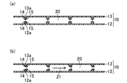
- the polymer films 12 and 13 are provided with a plurality of pairs of valves 12a and 13a protruding toward the flow path 20, and the electrodes 14 and 13a are respectively provided on the valves 12a and 13a. 15 may be formed.
- the polymer films 12 and 13 can function as a pump by expanding and contracting 13a in the same direction. Also in this case, as shown by an arrow 21 in FIG. 10B, a liquid such as blood can be sent (blooded) in the flow path 20.
- the polymer films 12 and 13 are expanded and contracted by applying a voltage so that the polymer films 12 and 13 can function as a pump. , 15 is not necessary.
- the electrical signal flowing in the body may be amplified and changed into a mechanical pressure signal, and a voltage may be applied to the electrodes 14 and 15 using this pressure signal.
- a plurality of electrodes (four electrodes in FIG. 11 (a)) 22 to 25 are provided on a part of the tubular polymer film 10, and these electrodes 22 to It is good also as a structure which gives a stirring function to the polymer film 10 by applying a voltage to 25 and deforming the polymer film 10 periodically as shown in FIG. 11 (b) and FIG. 11 (c).
- the polymer film 50 has a property of contracting when a positive voltage is supplied and expanding when a negative voltage is supplied.
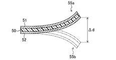
- the displacement difference ⁇ d was measured several times (in this example, 13 times) in increments of 0.5V between 0.5 and 5.0V. More specifically, for example, from the state shown in FIG. 12, a voltage of +0.5 V is supplied to the electrode 51 and a voltage of ⁇ 0.5 is supplied to the electrode 52 (of the polymer device 55a shown in FIG. 13). State) and a state in which a voltage of ⁇ 0.5 V is supplied to the electrode 51 and a voltage of +0.5 V is supplied to the electrode 52 (state of the polymer device 55b shown in FIG. 13), the displacement difference ⁇ d is 13 times. , And the average value was calculated. The results are shown in Table 1.
- the polymer device 55 can be controlled with simple voltage control. It can be seen that it can be extended and contracted to function as a pump.
- the polymer device 55 can serve as a mechanical pump for fluid such as blood.
- the present invention is suitable for a polymer actuator that can be used as a substitute for a mechanical pump and an artificial lung device including the polymer actuator.
Landscapes
- Health & Medical Sciences (AREA)
- Heart & Thoracic Surgery (AREA)
- Engineering & Computer Science (AREA)
- Cardiology (AREA)
- Hematology (AREA)
- Veterinary Medicine (AREA)
- Anesthesiology (AREA)
- Biomedical Technology (AREA)
- Life Sciences & Earth Sciences (AREA)
- Animal Behavior & Ethology (AREA)
- General Health & Medical Sciences (AREA)
- Public Health (AREA)
- Mechanical Engineering (AREA)
- Vascular Medicine (AREA)
- Emergency Medicine (AREA)
- Pulmonology (AREA)
- General Engineering & Computer Science (AREA)
- External Artificial Organs (AREA)
- Structures Of Non-Positive Displacement Pumps (AREA)
Abstract
ポリマーアクチュエータは、互いに対向して配置された一対のポリマーフィルム(12,13)と、一対のポリマーフィルム(12,13)上に複数設けられ、互いに対向して配置された一対の電極(14,15)と、一対のポリマーフィルム(12,13)の間に形成され、液体が流れる流路(20)と、一対の電極(14,15)に電圧を印加する電圧印加手段とを備える。ポリマーフィルム(12,13)は、一対の電極(14,15)に電圧を印加することにより伸縮する。
Description
本発明は、メカニカルなポンプの代用となるポリマーアクチュエータ、及びそれを備えた人工肺装置に関する。
従来、心臓手術等の際に、患者の呼吸機能及び循環機能を代行する目的で、体外式の人工肺装置が利用されている。
この人工肺装置は、まず、メカニカルポンプ(例えば、ローラポンプや遠心ポンプ)を使用して、人体(動脈)から血液を脱血するとともに、ガス交換部へと送血し、このガス交換部において、ガス交換(血液に酸素を付加するとともに二酸化炭素を除去する処理)が行われ、再び、メカニカルポンプを使用して、ガス交換が行われた血液を人体に送血する機能を有する(例えば、特許文献1,2参照)。
しかし、上記従来の人工肺装置においては、血流用として、メカニカルポンプが使用されているため、人工肺装置の小型化に対応することが困難であるという問題があった。
特に、近年、患者の利便性向上(例えば、移植待機患者におけるブリッジ使用の向上や、患者自身の肺機能回復を目的としたブリッジ使用の向上)の観点から、小型化され、人体に携帯可能な人工肺装置の要望が高まってきている。
そこで、本発明は、上述の問題に鑑みてなされたものであり、メカニカルポンプの代用となるコンパクトなポリマーアクチュエータ及びそれを備えた人工肺装置を提供することを目的とする。
上記目的を達成するために、本発明のポリマーアクチュエータは互いに対向して配置された一対のポリマーフィルムと、一対のポリマーフィルム上に複数設けられ、互いに対向して配置された一対の電極と、一対のポリマーフィルムの間に形成され、液体が流れる流路と、一対の電極に電圧を印加する電圧印加手段とを備え、ポリマーフィルムは、一対の電極に電圧を印加することにより伸縮することを特徴とする。
同構成によれば、メカニカルポンプの代用となるポリマーアクチュエータを提供することが可能になるため、例えば、血流用のポンプを小型化することが可能になる。従って、例えば、血流用のポンプを備える人工肺装置を小型化することができ、使用者(患者)の利便性を向上することが可能になる。
また、ポリマーフィルムは柔軟性を有するため、例えば、ポリマーフィルムを折り畳むことにより、大面積化が可能なポリマーアクチュエータを提供することが可能になる。
本発明のポリマーアクチュエータにおいては、電圧印加手段に接続され、電極に印加される電圧を決定する電圧制御手段を更に備え、電圧印加手段が、電圧制御手段により決定された電圧を一対の電極に印加する構成としてもよい。
同構成によれば、複数の一対の電極に対して異なる電圧を印加することが可能になるため、例えば、複数の一対の電極に対して時差を設けた電圧(例えば、三角波形を有する電圧)を印加することが可能になる。従って、簡単な電圧制御で、ポリマーフィルムを伸縮させてポンプとして機能させることが可能になる。
本発明のポリマーアクチュエータにおいては、電圧制御手段が、流路に流れる流体の流量に基づいて、電極に印加される電圧を決定する構成としてもよい。
同構成によれば、例えば、流体の流量に比例して、電極に印加される電圧が大きくなるように、電圧を決定することが可能になる。従って、ポリマーフィルムの伸縮量を大きくすることが可能になるため、多量の液体を送ることが可能になる。
本発明のポリマーアクチュエータにおいては、ポリマーフィルムが、ポリエーテル、ポリピロール、ポリフッ化ビニリデン、及びヘキサフルオロエチレンからなる群より選ばれる少なくとも1種により形成されていてもよい。
同構成によれば、汎用性のある材料により、電圧により伸縮する性質を有するポリマーフィルムを形成することができる。
本発明のポリマーアクチュエータにおいては、電極が、導電性のグラファイト、または導電性のカーボンナノチューブにより形成されていてもよい。
同構成によれば、汎用性のある導電材料により、ポリマーフィルムの伸縮に追従することができる電極を形成することができる。
また、本発明のポリマーアクチュエータは、メカニカルポンプの代用となり、流体用のポンプの小型化に対応できるという優れた特性を備えている。従って、本発明のポリマーアクチュエータは、人体に接続されたポリマーアクチュエータと、ポリマーアクチュエータに接続された人工肺とを備え、ポリマーアクチュエータを介して、人体と人工肺との間で血液の送血が行われる人工肺装置に好適に使用できる。
本発明によれば、メカニカルポンプの代用となり、流体用のポンプの小型化に対応できるポリマーアクチュエータを提供することができる。
以下、本発明の実施形態を図面に基づいて詳細に説明する。尚、本発明は、以下の実施形態に限定されるものではない。
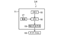
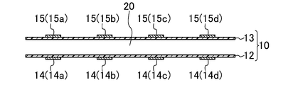
図1は、本発明の実施形態に係るポリマーアクチュエータを備える人工肺装置の全体構成を示す概略図であり、図2は、本発明の実施形態に係るポリマーアクチュエータの全体構成を示す図である。また、図3は、本発明の実施形態に係るポリマーアクチュエータにおけるポリマーフィルムを示す断面図である。
図1に示すように、人工肺装置1は、人工肺2と、人体に接続されたポリマーアクチュエータ3,4とを備えている。
人工肺2は、血液に酸素を付加するとともに炭酸ガスを除去するガス交換部5と、ガス交換を行う血液の温度調整を行う熱交換部6とを備えており、ポリマーアクチュエータ3,4に接続されている。
そして、人工肺装置1においては、まず、ポンプとして機能するポリマーアクチュエータ3を使用して、人体(動脈)から血液を脱血するとともに、脱血した血液をガス交換部5へと送血する。次いで、熱交換部6によりガス交換を行う血液の温度調整を行いながら、ガス交換部5においてガス交換が行われ、ポンプとして機能するポリマーアクチュエータ4を使用して、ガス交換が行われた血液を人体に送血する構成となっている。
即ち、人工肺装置1においては、ポリマーアクチュエータ3,4を介して、人体と人工肺2との間で血液の送血が行われる構成となっている。
なお、図1に示すように、人工肺装置1においては、酸素が含まれる空気が人工肺2に取り込まれるとともに、除去された二酸化炭素が含まれる空気が人工肺2から排出される構成となっている。空気の取り込み及び排出は、例えば、ポリマーアクチュエータの外部に設けられたポンプ(不図示)を使用して行うことができる。
ポリマーアクチュエータ3,4は、図2に示すように、ポリマーフィルム10と、ポリマーフィルム10に電圧を供給する電圧供給手段11とを備えている。
ポリマーフィルム10は、図3に示すように、互いに対向して配置された一対のポリマーフィルム12,13により構成されている。この一対のポリマーフィルム12,13は、所定の間隔を開けて配置されており、ポリマーフィルム12とポリマーフィルム13との間に血液等の流体が流れる流路20が形成されている。
また、ポリマーフィルム12には、複数の電極14が形成されるとともに、ポリマーフィルム13には、複数の電極15が形成され、電極14と電極15は、互いに対向して配置されている。
即ち、一対のポリマーフィルム12,13上に、互いに対向して配置された一対の電極14,15が複数設けられている。
ポリマーフィルム12,13は、上述の一対の電極14,15に電圧を印加することにより、伸縮する性質を有するものである。ポリマーフィルム12,13を形成する高分子材料としては、例えば、ポリエーテル等の電圧印加により高分子材料中のイオンが移動して収縮・膨張するイオン導電性高分子や、ポリピロール等の電圧印加によりイオンのドープ/脱ドープによって収縮・膨張する導電性高分子、及びポリフッ化ビニリデン等の電圧印加によって変形する圧電性高分子等を使用することができる。
なお、これらの高分子材料は、単独で使用してもよく、2種以上からなる共重合体を使用してもよい。例えば、圧電性高分子として、ポリフッ化ビニリデンとヘキサフルオロエチレンの共重合体を使用することができる。
電極14,15を形成する材料としては、導電性を有するとともに、ポリマーフィルム12,13の伸縮に追従することができるもの(即ち、ポリマーフィルム12,13と同様に、湾曲可能なもの)が使用される。より具体的には、例えば、ヒタゾル(日立化成(株)製)等のグラファイト系の導電性インク、カーボンナノチューブ等の導電性材料、及びカーボンナノチューブとイオン性液体(例えば、ブチルメチルイミダゾール)の複合体を使用することができる。
また、ポリマーフィルム12,13の表面に電極14,15を形成する方法としては、グラファイト系の導電性インクを使用して、ポリマーフィルム12,13の表面に電極14,15を印刷する方法や、カーボンナノチューブ等の導電性材料を溶媒中に溶解させて塗布・乾燥させる方法等を使用することができる。
電圧供給手段11は、図2に示すように、電極14,15に印加する電圧を決定する電圧制御手段としてのCPU16と、CPU16に電力を供給する電力供給手段である電源17と、記憶手段であるメモリ18とを備えている。
このCPU16には、上述の電源17、メモリ18、及びポリマーフィルム12,13に形成された電極14,15に電圧を印加する電圧印加手段19に接続されており、CPU16は、メモリ18に記憶されているプログラムに従い、電圧印加手段19の制御を行う構成となっている。
なお、この電圧供給手段11は、ポリマーフィルム12,13とは別個に形成してもよく、電極14,15と同様に、ポリマーフィルム12,13上に形成する構成としてもよい。
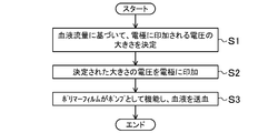
次に、本実施形態におけるポリマーアクチュエータ3,4のポンプ機能について説明する。図4は、本発明の実施形態に係るポリマーアクチュエータの動作手順を説明するためのフローチャートである。
まず、図4に示すように、CPU16が、メモリ18に記憶された血液流量に関す情報に基づいて、電極14,15に印加される電圧の大きさを決定する(ステップS1)。
より具体的には、CPU16は、ポリマーアクチュエータ3,4により送血される血液の流量に比例して、電極14,15に印加される電圧が大きくなるように、電圧の大きさを決定する。このような構成により、ポリマーフィルム12,13の伸縮量が大きくなるため、多くの血液を送血することが可能になる。
次いで、電圧の大きさに関する信号が、CPU16から電圧印加手段19に入力され、電圧印加手段19は、電極14,15に対して、決定された大きさの電圧を印加する(ステップS2)。
そうすると、電極14,15が形成されたポリマーフィルム12,13が伸縮して、ポリマーフィルム12,13がポンプとして機能し、ポリマーフィルム12,13が、人体(動脈)から血液を脱血してガス交換部5へと送血するとともに、ガス交換が行われた血液を人体に送血する(ステップS3)。
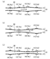
次に、ポリマーフィルム12,13の伸縮動作について説明する。図5は、本発明の実施形態に係るポリマーアクチュエータにおけるポリマーフィルムの伸縮動作を説明するための図であり、図6は、本発明の実施形態に係るポリマーアクチュエータにおけるポリマーフィルムに形成された各電極に印加される電圧の経時変化を示す図である。
本実施形態においては、電圧供給手段11により、電極14,15に対して、時差を設けて電圧を印加する(即ち、所定の時間遅れで変化する電圧を印加する)ことにより、ポリマーフィルム12,13を伸縮させる構成としている。
より具体的には、例えば、正の電圧を供給すると膨張し、負の電圧を供給すると収縮するポリマーフィルム12,13を使用し、図3に示すポリマーフィルム12,13に対して、図6に示す時差を設けた電圧(三角波形を有する電圧)を印加する場合、時刻T1においては、電極14a,15aに対して負の電圧が印加されるため、ポリマーフィルム12,13の電極14a,15aが形成された部分は収縮し、電極14c,15cに対して正の電圧が印加されるため、ポリマーフィルム12,13の電極14c,15cが形成された部分は膨張する。
また、図6に示すように、時刻T1においては、電極14b,15b、及び電極14d,15dに対して電圧は印加されないため、ポリマーフィルム12,13の電極14b,15b、及び電極14d,15dが形成された部分は伸縮しない。
従って、ポリマーフィルム12,13は、時刻T1において、図3に示す状態から、図5(a)に示す状態となる。
次に、時刻T1から所定時間が経過した時刻T2おいては、図6に示すように、電極14b,15bに対して負の電圧が印加されるため、ポリマーフィルム12,13の電極14b,15bが形成された部分は収縮し、電極14d,15dに対して正の電圧が印加されるため、ポリマーフィルム12,13の電極14d,15dが形成された部分は膨張する。
また、図6に示すように、時刻T2においては、電極14a,15a、及び電極14c,15cに対して電圧は印加されないため、ポリマーフィルム12,13の電極14a,15a、及び電極14c,15cが形成された部分は伸縮しない。
従って、ポリマーフィルム12,13は、時刻T2において、図5(a)に示す状態から、図5(b)に示す状態となる。
次に、時刻T2から所定時間が経過した時刻T3おいては、図6に示すように、電極14c,15cに対して負の電圧が印加されるため、ポリマーフィルム12,13の電極14c,15cが形成された部分は収縮し、電極14a,15aに対して正の電圧が印加されるため、ポリマーフィルム12,13の電極14a,15aが形成された部分は膨張する。
また、図6に示すように、時刻T3においては、電極14b,15b、及び電極14d,15dに対して電圧は印加されないため、ポリマーフィルム12,13の電極14b,15b、及び電極14d,15dが形成された部分は伸縮しない。
従って、ポリマーフィルム12,13は、時刻T3において、図5(b)に示す状態から、図5(c)に示す状態となる。
このように本実施形態においては、図5(a)~(c)に示すように、電極14,15に対して、時差を設けて電圧を印加することにより、ポリマーフィルム12,13を伸縮させ、ポリマーフィルム12,13をポンプとして機能させることにより、図5(a)~(c)の矢印21で示すように、流路20において、血液等の液体を送る(送血する)構成としている。
そして、このような構成により、ポリマーアクチュエータ3,4を、メカニカルポンプの代用として使用することが可能になるため、例えば、血流用のポンプを小型化することが可能になる。従って、人工肺装置1を小型化することができるとともに、使用者(患者)の利便性を向上することが可能になる。
また、ポリマーフィルム12,13は柔軟性を有するため、例えば、ポリマーフィルム12,13を折り畳むことにより、大面積化が可能なポリマーアクチュエータ3,4を提供することが可能になる。
また、上記従来のメカニカルポンプとは異なり、人体に適合して動作することが可能なポリマーアクチュエータ3,4を提供することが可能になる。
また、本実施形態においては、電圧印加手段19が、CPU16により決定された電圧を一対の電極14,15に印加するため、複数の一対の電極14,15の各々に対して異なる電圧を印加することが可能になる。従って、上述のごとく、例えば、複数の一対の電極14,15に対して時差を設けた電圧(例えば、三角波形を有する電圧)を印加することが可能になるため、簡単な電圧制御で、ポリマーフィルム12,13を伸縮させてポンプとして機能させることが可能になる。
なお、上述のCPU16として使用することができる回路の一例を図7に示す。この回路30は、電圧印加手段19に入力される電圧の大きさに関する信号を生成する回路であり、発振動作を開始するスタート回路であるNAND31と、信号を遅延させる遅延回路であるバッファ32と、バッファ32における入出力信号の論理積を出力する論理回路であるAND33とを備えている。
そして、この回路により生成された電圧の大きさに関する信号が、電圧印加手段19に入力され、電圧印加手段19は、電極14,15に対して、決定された大きさの電圧を印加する。このような回路30を使用することにより、電極14,15に対して、時差をつけて電圧を印加することが可能になる。
なお、上記実施形態は以下のように変更しても良い。
上記実施形態においては、遅延して変化する電圧として、三角波形を有する電圧を印加する構成としたが、例えば、正弦波形を有する電圧等、所定の時間遅れで変化する波形を有する電圧であれば、どのような電圧でも構わない。
また、ポリマーフィルム12の表面に電極14,15を設けるとともに、ポリマーフィルム13の表面に電極14,15を設ける構成としてもよい。
より具体的には、図8に示すように、ポリマーフィルム12の一方の表面(即ち、流路20と反対側の表面)35に複数の電極14を設けるとともに、他方の表面(即ち、流路20側の表面)36に複数の電極15を設け、更に、ポリマーフィルム13の一方の表面(即ち、流路20と反対側の表面)37に複数の電極15を設けるとともに、他方の表面(即ち、流路20側の表面)38に複数の電極14を設ける構成としてもよい。
この場合、図8に示すように、ポリマーフィルム12,13の各々において、互いに対向して配置された一対の電極14,15が複数設けられる。また、ポリマーフィルム12に設けられた一対の電極14,15と、ポリマーフィルム13に設けられた一対の電極14,15が、互いに対向して配置される。
そして、上述の実施形態と同様に、CPU16により、各電極14,15に印加される電圧を制御することにより、簡単な電圧制御で、ポリマーフィルム12,13を伸縮させてポンプとして機能させることが可能になる。
また、上記実施形態においては、互いに対向して配置された一対のポリマーフィルム12,13により構成されたポリマーフィルム10を使用する構成としたが、図9に示すように、チューブ状のポリマーフィルム10を使用する構成としてもよい。
この場合、図9に示すように、一対の電極14,15は、ポリマーフィルム10の表面(即ち、流路20と反対側の表面)10aに設けられ、互いに対向して配置される。
そして、上述の実施形態と同様に、CPU16により、各電極14,15に印加される電圧を制御することにより、簡単な電圧制御で、チューブ状のポリマーフィルム10を伸縮させてポンプとして機能させることが可能になる。
また、図10(a)に示すように、ポリマーフィルム12,13において、流路20に向けて突出する一対の弁12a,13aを複数設けるとともに、弁12a,13aの各々に上述の電極14,15を形成する構成としてもよい。
この場合、電極14,15に電圧を印加する(即ち、電極14,15に対して、周期的に反転させた電圧を印加する)ことにより、図10(b)に示すように、弁12a,13aを同一方向に伸縮させて、ポリマーフィルム12,13をポンプとして機能させることができる。そして、この場合も、図10(b)の矢印21で示すように、流路20において、血液等の液体を送る(送血する)ことができる。
なお、弁12a,13aの長さを更に長くして、弁12a,13aが閉じた状態(即ち、図10(a)に示す状態)において、弁12a,13aによって、流路20が塞がれるような構成としてもよい。
また、本発明においては、電圧を印加することにより、ポリマーフィルム12,13を伸縮させ、ポリマーフィルム12,13をポンプとして機能させることができればよく、必ずしも、ポリマーフィルム12,13の表面を電極14,15で挟み込む必要はない。
また、体内に流れる電気信号を、増幅して、メカニカルな圧力信号に変化させ、この圧力信号を用いて、電極14,15に電圧を印加する構成としてもよい。
また、図11(a)に示すように、チューブ状のポリマーフィルム10の一部に、複数の電極(図11(a)においては4個の電極)22~25を設け、これらの電極22~25に電圧を印加し、図11(b)、及び図11(c)に示すように、ポリマーフィルム10を周期的に変形させることにより、ポリマーフィルム10に攪拌機能を持たせる構成としてもよい。
以下に、本発明を実施例に基づいて説明する。なお、本発明は、これらの実施例に限定されるものではなく、これらの実施例を本発明の趣旨に基づいて変形、変更することが可能であり、それらを本発明の範囲から除外するものではない。
(ポリマーフィルムの変位測定)
まず、図12に示す、EMITFSI含有のフッ素化ポリマーフィルム(商品名:Kynar Flex 2801)により形成されたポリマーフィルム50と、このポリマーフィルム50の表面に設けられ、カーボンナノチューブにより形成された電極51,52からなるポリマーデバイス55を用意した。
まず、図12に示す、EMITFSI含有のフッ素化ポリマーフィルム(商品名:Kynar Flex 2801)により形成されたポリマーフィルム50と、このポリマーフィルム50の表面に設けられ、カーボンナノチューブにより形成された電極51,52からなるポリマーデバイス55を用意した。
なお、このポリマーフィルム50は、正の電圧を供給すると収縮し、負の電圧を供給すると膨張する性質を有する。
次に、図12に示す状態から、電極51に正の電圧を供給するとともに、電極52に負の電圧を供給した状態(図13に示すポリマーデバイス55aの状態)と、電極51に負の電圧を供給するとともに、電極52に正の電圧を供給した状態(図13に示すポリマーデバイス55bの状態)との変位差(即ち、図13に示すΔd)を測定し、ポリマーデバイス55におけるメカニカルポンプとしての有用性を評価した。
なお、変位差Δdの測定は、0.5~5.0Vの間で0.5V刻みで、複数回(本実施例においては、13回)行った。より具体的には、例えば、図12に示す状態から、電極51に+0.5Vの電圧を供給するとともに、電極52に-0.5の電圧を供給した状態(図13に示すポリマーデバイス55aの状態)と、電極51に-0.5Vの電圧を供給するとともに、電極52に+0.5Vの電圧を供給した状態(図13に示すポリマーデバイス55bの状態)との変位差Δdを、13回、測定し、その平均値を算出した。以上の結果を、表1に示す。

表1に示すように、供給する電圧が大きくなるに従って、変位差Δdも大きくなっており、各電極51,52に印加される電圧を制御することにより、簡単な電圧制御で、ポリマーデバイス55を伸縮させてポンプとして機能させることが可能であることが判る。
以上より、ポリマーデバイス55は、血液等の流体用のメカニカルポンプとしての役割を果たすことができることが判る。
以上説明したように、本発明は、メカニカルなポンプの代用となるポリマーアクチュエータ、及びそれを備えた人工肺装置に適している。
1 人工肺装置
2 人工肺
3 ポリマーアクチュエータ
4 ポリマーアクチュエータ
5 ガス交換部
6 熱交換部
10 ポリマーフィルム
11 電圧供給手段
12 ポリマーフィルム
12a 弁
13a 弁
13 ポリマーフィルム
14 電極
15 電極
16 CPU(電圧制御手段)
17 電源
18 メモリ
19 電圧印加手段
20 流路
30 回路
2 人工肺
3 ポリマーアクチュエータ
4 ポリマーアクチュエータ
5 ガス交換部
6 熱交換部
10 ポリマーフィルム
11 電圧供給手段
12 ポリマーフィルム
12a 弁
13a 弁
13 ポリマーフィルム
14 電極
15 電極
16 CPU(電圧制御手段)
17 電源
18 メモリ
19 電圧印加手段
20 流路
30 回路
Claims (6)
- 互いに対向して配置された一対のポリマーフィルムと、
前記一対のポリマーフィルム上に複数設けられ、互いに対向して配置された一対の電極と、
前記一対のポリマーフィルムの間に形成され、液体が流れる流路と、
前記一対の電極に電圧を印加する電圧印加手段と
を備え、
前記ポリマーフィルムは、前記一対の電極に電圧を印加することにより伸縮することを特徴とするポリマーアクチュエータ。 - 前記電圧印加手段に接続され、前記電極に印加される電圧を決定する電圧制御手段を更に備え、
前記電圧印加手段は、前記電圧制御手段により決定された電圧を前記一対の電極に印加することを特徴とする請求項1に記載のポリマーアクチュエータ。 - 前記電圧制御手段は、前記流路に流れる前記流体の流量に基づいて、前記電極に印加される電圧を決定することを特徴とする請求項2に記載のポリマーアクチュエータ。
- 前記ポリマーフィルムが、ポリエーテル、ポリピロール、ポリフッ化ビニリデン、及びヘキサフルオロエチレンからなる群より選ばれる少なくとも1種により形成されていることを特徴とする請求項1~請求項3のいずれか1項に記載のポリマーアクチュエータ。
- 前記電極が、導電性のグラファイト、または導電性のカーボンナノチューブにより形成されていることを特徴とする請求項1~請求項4のいずれか1項に記載のポリマーアクチュエータ。
- 請求項1~請求項5のいずれか1項に記載され、人体に接続されたポリマーアクチュエータと、
前記ポリマーアクチュエータに接続された人工肺と
を備え、
前記ポリマーアクチュエータを介して、前記人体と前記人工肺との間で血液の送血が行われることを特徴とする人工肺装置。
Priority Applications (1)
| Application Number | Priority Date | Filing Date | Title |
|---|---|---|---|
| JP2015506598A JPWO2014148017A1 (ja) | 2013-03-18 | 2014-03-13 | ポリマーアクチュエータ及びそれを備えた人工肺装置 |
Applications Claiming Priority (2)
| Application Number | Priority Date | Filing Date | Title |
|---|---|---|---|
| JP2013-054985 | 2013-03-18 | ||
| JP2013054985 | 2013-03-18 |
Publications (1)
| Publication Number | Publication Date |
|---|---|
| WO2014148017A1 true WO2014148017A1 (ja) | 2014-09-25 |
Family
ID=51579715
Family Applications (1)
| Application Number | Title | Priority Date | Filing Date |
|---|---|---|---|
| PCT/JP2014/001426 Ceased WO2014148017A1 (ja) | 2013-03-18 | 2014-03-13 | ポリマーアクチュエータ及びそれを備えた人工肺装置 |
Country Status (2)
| Country | Link |
|---|---|
| JP (1) | JPWO2014148017A1 (ja) |
| WO (1) | WO2014148017A1 (ja) |
Cited By (1)
| Publication number | Priority date | Publication date | Assignee | Title |
|---|---|---|---|---|
| WO2017129453A1 (en) * | 2016-01-25 | 2017-08-03 | Koninklijke Philips N.V. | Actuator device based on an electroactive polymer |
Citations (7)
| Publication number | Priority date | Publication date | Assignee | Title |
|---|---|---|---|---|
| JPH0275776A (ja) * | 1988-09-10 | 1990-03-15 | Fuji Kobunshi Kk | 進行波圧電フィルムポンプ |
| JPH03107585A (ja) * | 1989-09-20 | 1991-05-07 | Fujitsu Ltd | 圧電ポンプ |
| JPH0727056A (ja) * | 1993-07-06 | 1995-01-27 | Hitachi Ltd | ポンプ |
| JP2003286958A (ja) * | 2002-03-27 | 2003-10-10 | Dainippon Screen Mfg Co Ltd | 液体供給装置 |
| JP2009041554A (ja) * | 2007-07-17 | 2009-02-26 | Alps Electric Co Ltd | 圧電ポンプ |
| JP2009138573A (ja) * | 2007-12-04 | 2009-06-25 | Tokai Rubber Ind Ltd | 蠕動型ポンプ |
| JP2010174883A (ja) * | 2008-12-30 | 2010-08-12 | Masao Suzuki | 微少流量制御装置 |
-
2014
- 2014-03-13 WO PCT/JP2014/001426 patent/WO2014148017A1/ja not_active Ceased
- 2014-03-13 JP JP2015506598A patent/JPWO2014148017A1/ja active Pending
Patent Citations (7)
| Publication number | Priority date | Publication date | Assignee | Title |
|---|---|---|---|---|
| JPH0275776A (ja) * | 1988-09-10 | 1990-03-15 | Fuji Kobunshi Kk | 進行波圧電フィルムポンプ |
| JPH03107585A (ja) * | 1989-09-20 | 1991-05-07 | Fujitsu Ltd | 圧電ポンプ |
| JPH0727056A (ja) * | 1993-07-06 | 1995-01-27 | Hitachi Ltd | ポンプ |
| JP2003286958A (ja) * | 2002-03-27 | 2003-10-10 | Dainippon Screen Mfg Co Ltd | 液体供給装置 |
| JP2009041554A (ja) * | 2007-07-17 | 2009-02-26 | Alps Electric Co Ltd | 圧電ポンプ |
| JP2009138573A (ja) * | 2007-12-04 | 2009-06-25 | Tokai Rubber Ind Ltd | 蠕動型ポンプ |
| JP2010174883A (ja) * | 2008-12-30 | 2010-08-12 | Masao Suzuki | 微少流量制御装置 |
Cited By (2)
| Publication number | Priority date | Publication date | Assignee | Title |
|---|---|---|---|---|
| WO2017129453A1 (en) * | 2016-01-25 | 2017-08-03 | Koninklijke Philips N.V. | Actuator device based on an electroactive polymer |
| US11251357B2 (en) | 2016-01-25 | 2022-02-15 | Koninklijke Philips N.V. | Actuator device based on an electroactive polymer |
Also Published As
| Publication number | Publication date |
|---|---|
| JPWO2014148017A1 (ja) | 2017-02-16 |
Similar Documents
| Publication | Publication Date | Title |
|---|---|---|
| Sharma et al. | Hydrogen-bond-triggered hybrid nanofibrous membrane-based wearable pressure sensor with ultrahigh sensitivity over a broad pressure range | |
| Must et al. | Ionic and capacitive artificial muscle for biomimetic soft robotics | |
| US7834527B2 (en) | Dielectric elastomer fiber transducers | |
| Amjadi et al. | High-performance multiresponsive paper actuators | |
| Tang et al. | A speedy, amphibian, robotic cube: Resonance actuation by a dielectric elastomer | |
| Godaba et al. | Giant voltage-induced deformation of a dielectric elastomer under a constant pressure | |
| US9882117B2 (en) | Actuator including a dielectric elastomer and electrode films | |
| US20150320295A1 (en) | Activated polymer articulated instruments and methods of insertion | |
| Lu et al. | Ionic polymer–metal composites: From material engineering to flexible applications | |
| Xu et al. | Implantable Cardiac Kirigami‐Inspired Lead‐Based Energy Harvester Fabricated by Enhanced Piezoelectric Composite Film | |
| Kim et al. | Multilayered MoS2 sphere-based triboelectric–flexoelectric nanogenerators as self-powered mechanical sensors for human motion detection | |
| Lu et al. | Piezoionic skin sensors for wearable applications | |
| Wang et al. | Analysis and application of a rolled dielectric elastomer actuator with two degrees of freedom | |
| Zhang et al. | Recent advances in MXene‐based flexible pressure sensors for medical monitoring | |
| Saha et al. | Self-powered ionic tactile sensors | |
| JP2016513542A (ja) | 小血管系補助ガイドワイヤ | |
| WO2014148017A1 (ja) | ポリマーアクチュエータ及びそれを備えた人工肺装置 | |
| Wang et al. | A unified system identification approach for a class of pneumatically-driven soft actuators | |
| Afzal et al. | Study on the induced voltage in piezoelectric smart material (PZT) using ANSYS electric & fuzzy logic | |
| Park et al. | An intraventricular soft robotic pulsatile assist device for right ventricular heart failure | |
| JP6630000B2 (ja) | 摩擦制御装置および方法 | |
| Wei et al. | Vinyl Acetate‐Enhanced Polyvinyl Chloride Gel with High Electroadhesion and Self‐Heating‐Tunability for Soft Robots in Freezing Environments | |
| Torop et al. | Microporous and mesoporous carbide-derived carbons for strain modification of electromechanical actuators | |
| JP5114722B2 (ja) | センサ機能付き統合型ソフトアクチュエータ | |
| André et al. | Piezo-Ionic Actuator for Haptic Feedback |
Legal Events
| Date | Code | Title | Description |
|---|---|---|---|
| 121 | Ep: the epo has been informed by wipo that ep was designated in this application |
Ref document number: 14770156 Country of ref document: EP Kind code of ref document: A1 |
|
| ENP | Entry into the national phase |
Ref document number: 2015506598 Country of ref document: JP Kind code of ref document: A |
|
| NENP | Non-entry into the national phase |
Ref country code: DE |
|
| 122 | Ep: pct application non-entry in european phase |
Ref document number: 14770156 Country of ref document: EP Kind code of ref document: A1 |