WO2014147824A1 - 磁気質検出装置 - Google Patents
磁気質検出装置 Download PDFInfo
- Publication number
- WO2014147824A1 WO2014147824A1 PCT/JP2013/058353 JP2013058353W WO2014147824A1 WO 2014147824 A1 WO2014147824 A1 WO 2014147824A1 JP 2013058353 W JP2013058353 W JP 2013058353W WO 2014147824 A1 WO2014147824 A1 WO 2014147824A1
- Authority
- WO
- WIPO (PCT)
- Prior art keywords
- magnetic
- sensor
- paper sheet
- magnetic sensor
- magnetic field
- Prior art date
Links
Images


Classifications
-
- G—PHYSICS
- G07—CHECKING-DEVICES
- G07D—HANDLING OF COINS OR VALUABLE PAPERS, e.g. TESTING, SORTING BY DENOMINATIONS, COUNTING, DISPENSING, CHANGING OR DEPOSITING
- G07D7/00—Testing specially adapted to determine the identity or genuineness of valuable papers or for segregating those which are unacceptable, e.g. banknotes that are alien to a currency
- G07D7/04—Testing magnetic properties of the materials thereof, e.g. by detection of magnetic imprint
-
- G—PHYSICS
- G01—MEASURING; TESTING
- G01N—INVESTIGATING OR ANALYSING MATERIALS BY DETERMINING THEIR CHEMICAL OR PHYSICAL PROPERTIES
- G01N27/00—Investigating or analysing materials by the use of electric, electrochemical, or magnetic means
- G01N27/72—Investigating or analysing materials by the use of electric, electrochemical, or magnetic means by investigating magnetic variables
-
- G—PHYSICS
- G01—MEASURING; TESTING
- G01R—MEASURING ELECTRIC VARIABLES; MEASURING MAGNETIC VARIABLES
- G01R33/00—Arrangements or instruments for measuring magnetic variables
- G01R33/12—Measuring magnetic properties of articles or specimens of solids or fluids
-
- G—PHYSICS
- G06—COMPUTING; CALCULATING OR COUNTING
- G06K—GRAPHICAL DATA READING; PRESENTATION OF DATA; RECORD CARRIERS; HANDLING RECORD CARRIERS
- G06K19/00—Record carriers for use with machines and with at least a part designed to carry digital markings
- G06K19/06—Record carriers for use with machines and with at least a part designed to carry digital markings characterised by the kind of the digital marking, e.g. shape, nature, code
- G06K19/08—Record carriers for use with machines and with at least a part designed to carry digital markings characterised by the kind of the digital marking, e.g. shape, nature, code using markings of different kinds or more than one marking of the same kind in the same record carrier, e.g. one marking being sensed by optical and the other by magnetic means
- G06K19/10—Record carriers for use with machines and with at least a part designed to carry digital markings characterised by the kind of the digital marking, e.g. shape, nature, code using markings of different kinds or more than one marking of the same kind in the same record carrier, e.g. one marking being sensed by optical and the other by magnetic means at least one kind of marking being used for authentication, e.g. of credit or identity cards
- G06K19/12—Record carriers for use with machines and with at least a part designed to carry digital markings characterised by the kind of the digital marking, e.g. shape, nature, code using markings of different kinds or more than one marking of the same kind in the same record carrier, e.g. one marking being sensed by optical and the other by magnetic means at least one kind of marking being used for authentication, e.g. of credit or identity cards the marking being sensed by magnetic means
Definitions
- the present invention relates to a magnetic quality detection device for detecting the magnetic properties of paper sheets, and more particularly to a magnetic quality detection device capable of distinguishing and detecting a plurality of types of magnetic materials having different coercive forces.
- Magnetic ink containing a magnetic material is used for printing paper sheets such as checks and gift certificates.
- Magnetic ink includes hard magnetic ink and soft magnetic ink having different coercive forces. If the magnetic ink used in the paper sheet can be accurately detected, the authenticity of the paper sheet can be determined.
- a magnetic field perpendicular to a transport path for transporting a paper sheet is generated to detect the magnetism of the paper sheet passing through the magnetic field.
- a magnetic quality detection device is disclosed.
- the upper unit and the lower unit are arranged so as to sandwich paper sheets to be conveyed from above and below.
- two magnets are housed in a form connected by a yoke, and a magnetic field is generated by these magnets with the conveyance path interposed therebetween.
- Magnetic ink used in paper sheets because a magnetic field is generated at the position where the sensor for detecting the magnetism of the paper sheets passes vertically through the paper sheets in the direction perpendicular to the paper sheet conveyance direction. Can be detected with high accuracy.
- the magnets in each unit may vibrate due to vibrations caused by the operation of the transport mechanism or the like and become a noise source.
- a conveyance roller or the like constituting the conveyance mechanism cannot be disposed on the conveyance path positioned between the upper and lower units. For this reason, when the upper and lower unit sizes are increased, the sheets may not be stably conveyed.
- the present invention has been made to solve the above-described problems caused by the prior art, and can detect a plurality of types of magnetic materials having different coercive forces while realizing downsizing of the apparatus.
- An object is to provide an apparatus.
- the present invention provides a magnetic quality detection device for detecting the magnetic quality of a magnetic substance contained in a paper sheet conveyed through a conveyance path, wherein the conveyance path is The direction of the magnetic field is reversed after the magnetic field intensity decreases in the magnetic field in the direction perpendicular to the conveyance direction of the conveyed paper sheet and parallel to the conveyance surface of the paper sheet and reaches zero after reaching the conveyance direction.
- a magnetic unit that generates a magnetic field whose magnetic field strength increases again in a direction, and a magnetic material of a paper sheet that is disposed at a position where the magnetic field strength is different in the magnetic field of the magnet unit and is transported through the transport path And detecting the magnetic quality of the magnetic material contained in the paper sheet based on the output signals of the plurality of magnetic sensors when the magnetic material is detected.
- the paper sheet that has been detected as containing a magnetic material having a predetermined magnetic property on the condition that the output value of another magnetic sensor other than the predetermined magnetic sensor is other than 0 A true / false determining unit that determines that the paper is a true paper sheet is provided.
- the present invention provides the above-described invention, in the case where there is no magnetic sensor in which the output values of the plurality of magnetic sensors when detecting a magnetic substance contained in a true paper sheet are substantially zero, the plurality of magnetic sensors Of the two adjacent magnetic sensors out of phase are determined to contain a magnetic material having a predetermined magnetic property, and the paper sheet from which the magnetism has been detected is a true paper sheet. It is characterized by having a true / false determination unit that determines that the image is a class.
- the magnetic quality of the paper sheet conveyed in the conveyance path at a position set based on the magnetization characteristic of the magnetic material having a predetermined coercive force in the magnetic field by the magnet unit.
- a second magnetic sensor for detecting the magnetic quality of the paper sheet conveyed on the conveyance path at a position different from that of the first magnetic sensor.
- the present invention is the above invention, wherein the magnet unit generates at least a first magnet that generates a magnetic field in a direction perpendicular to a paper sheet transport direction and parallel to the paper sheet transport surface. And a second magnet that generates a magnetic field opposite to the magnetic field generated by the first magnet on the downstream side in the transport direction from the magnet.
- the present invention is the above invention, wherein the first magnetic sensor is configured to transfer the magnetic body magnetized in a saturated magnetization state in the magnetic field based on a magnetization characteristic of the magnetic body having a predetermined coercive force. It is arranged in a position where the magnetization intensity becomes zero by being conveyed in the direction.
- the present invention determines that the magnetic body has a predetermined coercive force. It is characterized by.
- the present invention is characterized in that, in the above invention, the coercive force of the detected magnetic material is determined based on the phases of the magnetic detection signal from the first magnetic sensor and the magnetic detection signal from the second magnetic sensor.
- the present invention is characterized in that, in the above-mentioned invention, the magnetic field by the magnet unit has a magnetic field intensity that makes a magnetic material to be detected upstream of the first magnetic sensor in a saturated magnetization state.
- the present invention is the above invention, wherein the magnetic field generated by the magnet unit gradually decreases to zero as the magnetic field advances in the transport direction, and then a zero magnetic field continues in the transport direction.
- the magnetic field strength is increased again by reversing the direction of the magnetic field.
- the present invention is characterized in that in the above-mentioned invention, an adjustment mechanism for changing the magnetic field intensity at the position where the first sensor is arranged is further provided.
- the first magnetic sensor and the second magnetic sensor are sensors that detect a change in magnetic flux density caused by the magnetized magnetic material passing through the magnetic field.
- the present invention is the above invention, wherein the first magnetic sensor has a magnetic body to be detected conveyed on the conveyance path among a plurality of magnetic sensors each arranged at a position where the magnetic field strength is different. It is selected based on the output of each magnetic sensor obtained at the time.
- the magnetic sensor showing a positive output and a negative output arranged next to the magnetic sensor are provided.
- the magnetic sensor shown is selected, and the two magnetic sensors are used as the first magnetic sensor.
- a magnet unit is disposed either above or below a transport path for transporting a magnetic material to be subjected to magnetism detection, and a magnetic field is generated in a direction perpendicular to the transport direction and parallel to the transport surface. Since magnetic detection is performed, the size of the magnetic quality detection device can be reduced and the manufacturing cost can be reduced.
- a plurality of magnetic sensors can be arranged at different positions of the magnetic field strength, and the magnetic sensor to be used can be selected. Therefore, according to the magnetic material included in the paper sheet to be processed By selecting a magnetic sensor, it is possible to detect the magnetic material contained in various paper sheets and determine the authenticity of the paper sheets.
- the magnetic field for detecting the magnetic material can be generated with only two magnets, the size of the magnetic quality detection device can be reduced and the manufacturing cost can be reduced.
- the position at which the output value when the first magnetic sensor passes through the magnetic body is substantially 0 (zero) by using the two magnetic sensors to match the magnetization characteristics of the predetermined magnetic body.
- the second magnetic sensor is disposed at a position where an output corresponding to the magnetization state can be obtained when the magnetic material passes, the passage of the magnetic material can be detected with high accuracy.
- the coercive force of the detected magnetic body depends on whether the output signals of the first magnetic sensor and the second magnetic sensor when detecting the magnetic body are in phase or in reverse phase. Since it can be determined whether it is larger or smaller than the coercive force of the magnetic material used for setting the arrangement position of the magnetic sensor, a plurality of types of magnetic materials can be distinguished and detected.
- the magnetic field strength at the position where the first sensor is disposed can be changed. Therefore, the magnetic field strength is changed according to the magnetic material to be detected, and the magnetic quality of various magnetic materials can be accurately set. Can be detected.
- FIG. 1 is a diagram for explaining an outline of a magnetic quality detection method by the magnetic quality detection apparatus according to the present embodiment.
- FIG. 2 is a diagram illustrating a schematic configuration of the magnetic quality detection device according to the present embodiment.
- FIG. 3 is a diagram for explaining an example of a detection signal obtained by the magnetic quality detection device when a magnetic pattern is printed on a paper sheet with a plurality of types of magnetic inks having different coercive forces.
- FIG. 4 is a diagram for explaining a method for adjusting and changing the magnetic field strength at the position where the first magnetic sensor is arranged in the magnetic quality detection device.
- FIG. 5 is a diagram for explaining a different configuration example of the magnetic quality detection device.
- FIG. 6 is a diagram illustrating an example in which the arrangement positions and magnetic forces of two magnets used in the magnetic quality detection device are different.
- FIG. 7 is a diagram illustrating an example in which the shapes of magnets used in the magnetic quality detection device are different.
- FIG. 8 is a diagram illustrating an example in which the configuration of the magnet used in the magnetic quality detection device is different.
- FIG. 9 is a diagram illustrating a different configuration example of the magnetic quality detection device.
- the magnetic quality detection apparatus has a function of detecting magnetism by a magnetic material such as magnetic ink used in paper sheets such as checks, gift certificates, and securities.
- the magnetic quality detection device is used, for example, in a paper sheet processing apparatus to detect the magnetic quality of a magnetic material contained in the paper sheet and determine whether or not it is a true paper sheet.
- the magnetic material to be detected by the magnetic quality detection device is not particularly limited, but the following description will be made taking magnetic ink used in paper sheets as an example.
- FIG. 1 is a schematic diagram for explaining an outline of a magnetic quality detection method for detecting a magnetic material by a magnetic quality detection device.
- FIG. 1B shows saturation magnetization curves (BH curves) of a plurality of types of magnetic inks M1 to M3 to be detected
- FIG. 1A shows a magnetic for distinguishing and detecting the magnetic inks M1 to M3.
- the structure outline of a quality detection apparatus is shown.
- FIG. 1C shows an output signal from the sensor obtained when the magnetic ink M1 to M3 shown in FIG. 1B is detected by the magnetic quality detection apparatus having the configuration shown in FIG. Show.
- the magnitudes of the coercive forces of the magnetic inks M1 to M3 have a relationship of M3> M2> M1.
- the output signal of the magnetic sensor described below in the present embodiment is, for example, a voltage value representing a change in the resistance value of the magnetoresistive element.
- the magnetic quality detection device includes a magnet unit that generates a magnetic field, and a first magnetic sensor 10 and a second magnetic sensor 20 for detecting a magnetic material that passes through the magnetic field.
- the first magnetic sensor 10 and the second magnetic sensor 20 are sensors that use a magnetic detection element that detects a change in magnetic flux density of a bias magnetic field accompanying the passage of a magnetic material.
- a magnetoresistive element such as an anisotropic magnetoresistive element (AMR), a semiconductor magnetoresistive element (SMR), or a giant magnetoresistive element (GMR)
- AMR anisotropic magnetoresistive element
- SMR semiconductor magnetoresistive element
- GMR giant magnetoresistive element
- the first magnetic sensor 10 and the second magnetic sensor 20 detect the fluctuation of the magnetic field in the vertical direction (Z-axis direction) or the front-back direction (X-axis direction) with respect to the paper sheet surface of the paper sheet 100 being conveyed. Includes a magnetic sensing element disposed on the surface.
- FIG. 1A shows only the magnetic field generated by the magnet unit, and details of the magnet unit will be described later.
- a broken line arrow indicates the conveyance direction of the paper sheet 100 conveyed on the conveyance path
- the direction and length of the solid line arrow indicate the magnetic field direction and the magnetic field strength, respectively.
- a magnetic field is generated in the conveyance direction (X-axis direction) of the paper sheet 100 and the direction (Z-axis) perpendicular to the conveyance surface (XY plane).
- the direction is perpendicular to the transport direction (X axis) of the paper sheet 100 and parallel to the transport surface (XY plane) of the paper sheet 100.
- One feature is to generate a magnetic field.
- the magnetic field of the magnetic quality detection device is changed to a magnetic field after the magnetic field intensity gradually decreases from the position where the magnetic material to be detected is magnetized upstream of the first magnetic sensor 10 to 0 (zero).
- the magnetic field strength gradually increases again with the direction of.
- the magnetic field strength at the magnetization position P1 is set so that the magnetic inks M1 to M3 are in a saturated magnetization state at the position P1 at which they are magnetized.
- the value of the magnetic field strength at the magnetization position P1 is set to at least twice the maximum coercive force of the magnetic material to be magnetized, but the magnetic field strength at the magnetization position P1 is at least three times the maximum coercivity of the magnetic material. It is preferable that
- the magnetization intensity of the magnetic ink M2 that is in the saturation magnetization state at the magnetization position P1 is the saturation magnetization.
- the first magnetic sensor 10 is arranged at a position P2 on the conveyance path corresponding to a point 202 that is 0 (zero) on the curve. That is, in the magnetic field, the first magnetic sensor 10 is disposed at the position P2 corresponding to the magnetic field strength at which the magnetic ink M2 magnetized in the saturation magnetization state is transported through the transport path and the magnetization strength becomes 0 (zero). Is done.
- the arrangement position of the second magnetic sensor 20 is not particularly limited as long as it is a position other than the position P2.
- the second magnetic sensor 20 is positioned at a position P3 on the conveyance path corresponding to the point 204 where the saturation magnetization curves of the magnetic inks M1 to M3 intersect. Deploy. That is, in the magnetic field, the second magnetic sensor 20 is disposed at a position P3 corresponding to the magnetic field strength of the point 204 on the saturation magnetization curve shown in FIG.
- the first magnetic sensor 10 When the paper sheet 100 is transported along the transport path and the magnetic ink M1 first reaches the position P2, the first magnetic sensor 10 causes the point 201 on the saturation magnetization curve of the magnetic ink M1 shown in FIG. Is detected. Next, when the magnetic ink M2 reaches the position P2, in the first magnetic sensor 10, the detection result is 0 (zero) corresponding to the point 202 on the saturation magnetization curve of the magnetic ink M2. When the magnetic ink M3 reaches the position P2, the first magnetic sensor 10 detects the magnetization intensity corresponding to the point 203 on the saturation magnetization curve of the magnetic ink M3.
- the magnetization intensity (point 201) of the magnetic ink M1 is in the first quadrant and the magnetization intensity (point 203) of the magnetic ink M3 is in the fourth quadrant. Then, detection results of opposite phases are obtained with the magnetic ink M1 and the magnetic ink M3.
- the magnetic inks M1 to M3 show the magnetization intensity corresponding to the point 204 on the saturation magnetization curve shown in FIG. In 20, the same detection result is obtained for each of the magnetic inks M1 to M3.
- the second magnetic sensor 20 can obtain the same phase detection result for all the magnetic inks M1 to M3.
- the first magnetic sensor 10 outputs signals having opposite phases when the magnetic ink M1 passes and when the magnetic ink M3 passes, and also the magnetic ink M2.
- the output signal when the signal passes is substantially 0 (zero).
- the second magnetic sensor 20 outputs signals having the same phase with the magnetic inks M1 to M3 with substantially the same magnitude.
- FIG. 1C in order to compare the detection results of the magnetic inks M1 to M3 by the first magnetic sensor 10 and the second magnetic sensor 20, the corresponding sensor outputs are shown side by side.
- the time of measurement there is a time difference between the timing measured by the first magnetic sensor 10 and the timing measured by the second magnetic sensor according to the transport distance and the transport speed from the position P2 to the position P3.
- the magnetic quality detection device recognizes the relationship between the position of the paper sheet 100 and the output values from the first magnetic sensor 10 and the second magnetic sensor 20 in cooperation with a transport mechanism (not shown) that transports the paper sheet 100. .
- the detection results of the magnetic inks M1 to M3 obtained by the first magnetic sensor 10 and the detections of the magnetic inks M1 to M3 obtained by the second magnetic sensor 20 are obtained.
- the correspondence with the result can be recognized.
- the magnetic detection device specifies the correspondence between the position of the paper sheet 100 and the magnetic detection result
- other devices connected to both the transport mechanism and the magnetic detection device are It may be an aspect performed based on position information acquired from the transport mechanism and magnetism detection information acquired from the magnetic quality detection device.
- the sensor outputs from the first magnetic sensor 10 and the second magnetic sensor 20 By comparing the sensor outputs from the first magnetic sensor 10 and the second magnetic sensor 20 thus obtained, it is possible to identify which of the magnetic inks M1 to M3 is the detected magnetic body. Specifically, when the same magnetic sensor output is obtained by the first magnetic sensor 10 and the second magnetic sensor 20, it is determined that the detected magnetic material is the magnetic ink M1, and the sensor output of the opposite phase is obtained. If it has been detected, it is determined that the detected magnetic material is the magnetic ink M3.
- the second magnetic sensor 20 detects magnetism even though the sensor output value of the first magnetic sensor 10 is substantially 0 (zero), it is determined that the detected magnetic body is the magnetic ink M2. .
- the output value of the first magnetic sensor 10 is approximately 0 (zero), whether the first magnetic sensor 10 alone is the detection result of the magnetic ink M2 or the detection result indicating that no magnetic material is present.
- the second magnetic sensor 20 determines that the detected magnetic material is the magnetic ink M2.
- the magnetic quality detection device can distinguish and detect magnetic inks having different coercive forces, even when magnetic inks having different coercive forces are used for the true paper sheet 100.
- Each magnetic ink can be detected and determined to be a true paper sheet 100.
- the paper sheet 100 includes three magnetic inks M1 to M3. Even when only the magnetic ink M2 is included, if the magnetic ink M2 is detected, it is determined that the sheet is a true paper sheet 100, and when no magnetism is detected or a different magnetic ink such as the magnetic ink M1 or M3 is detected. If it is determined, it can be determined that the paper sheet 100 is not true.
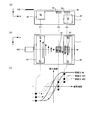
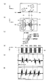
- FIG. 2 is a diagram illustrating a schematic configuration of the magnetic quality detection device 1.
- 2A shows a configuration of the magnetic quality detection device 1 viewed from the Y-axis direction
- FIG. 2B shows a configuration viewed from the Z-axis direction.
- FIG. 2C is a diagram showing the relationship between the arrangement positions of the first magnetic sensor 10 and the second magnetic sensor 20 used in the magnetic quality detection device 1 and the coercivity of the magnetic ink to be detected. is there.
- the broken line arrows indicate the conveyance direction of the paper sheet 100
- the direction and length of the solid line arrows indicate the direction of the magnetic field and the magnetic field strength, respectively.
- the magnetic quality detection device 1 is used by being installed below the conveyance path through which the paper sheet 100 is conveyed.
- the magnetic quality detection device 1 detects a change in magnetic flux density generated according to the magnetic characteristics of the two magnets 30 and 40 forming a magnet unit for generating a magnetic field and the paper sheet 100 passing through the bias magnetic field.
- the first magnetic sensor 10 and the second magnetic sensor 20 are included.
- the paper sheet 100 is transported in the X-axis direction above the magnetic quality detection device 1 by a transport mechanism including a roller (not shown).
- a signal relating to the conveyance timing by the conveyance mechanism is input to the magnetic quality detection device 1, and based on this signal, the paper sheet that passes through the arrangement positions of the first magnetic sensor 10 and the second magnetic sensor 20 While identifying the position of the class 100, the output signal from each sensor is recorded.
- the magnetic quality detection device 1 has a processing substrate (not shown) for processing output signals from the first magnetic sensor 10 and the second magnetic sensor 20.
- Conveying mechanism for conveying paper sheet 100 measuring method using positional information of paper sheet 100 conveyed by the conveying mechanism, measuring circuit and measuring method using various magnetic detection elements such as magnetoresistive element and Hall element Since the conventional technology can be used for the above, detailed description thereof will be omitted, and the following description of the features relating to the configuration of the magnetic quality detection device 1 will be continued.
- the two rectangular parallelepiped magnets 30 and 40 forming the magnet unit are arranged apart in the X-axis direction with their longitudinal directions parallel to the Y-axis direction and their polarities reversed.
- the direction of the magnetic field at the position of the magnet 30 on the upstream side of the first magnetic sensor 10 in the transport direction is the transport surface (XY) of the paper sheet 100.
- the magnetic field strength gradually decreases from the position P1 in the transport direction, and 0 (zero) at the position between the two magnets 30 and 40. ), The magnetic field strength gradually increases with the direction of the magnetic field reversed.
- the magnetic ink of the paper sheet 100 to be detected is magnetized in a saturated magnetization state at a position P1 that is upstream of the first magnetic sensor 10 and the second magnetic sensor 20 in the transport direction.
- the magnetic field strength at the magnetization position P1 is at least twice the maximum coercive force 300 Oe. For example, three times 900G.
- the arrangement positions of the first magnetic sensor 10 and the second magnetic sensor 20 are set based on the magnetic field generated by the magnets 30 and 40 and the magnetization characteristics of the magnetic ink to be detected. For example, based on the magnetization characteristics of a magnetic ink having a coercive force 220 Oe having a coercive force among the three types of magnetic inks having coercive forces 90, 220 and 300 Oe shown in FIG.
- the first magnetic sensor 10 is disposed at a position P2 at which the magnetization intensity becomes 0 (zero) after being magnetized at the magnetization position P1 while moving along the transport path.
- the position of the second magnetic sensor 20 is set to a position different from the arrangement position P2 of the first magnetic sensor 10.
- the 2nd magnet 20 is arrange
- the arrangement position of the first magnetic sensor 10 is P2, and the second magnetic sensor 20 is arranged based on the magnetization characteristics of the magnetic ink having the coercive force 220Oe and the magnetic field strength of the bias magnetic field.
- the arrangement position is position P3
- the output value of the first magnetic sensor 10 when the magnetic ink having a coercive force of 220 Oe is detected is substantially 0 (zero).
- a sensor output corresponding to the magnetization intensity is obtained from the second magnetic sensor 20.
- the magnetization intensities corresponding to the positions P2 and P3 are both in the first quadrant, so that the same phase from the first magnetic sensor 10 and the second magnetic sensor 20 is obtained. Is output.
- the magnetization intensity corresponding to the position P2 is in the fourth quadrant, whereas the magnetization intensity corresponding to the position P3 is in the first quadrant. Therefore, signals having opposite phases are detected from the first magnetic sensor 10 and the second magnetic sensor 20.
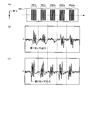
- FIG. 3 is a diagram illustrating an example of a detection signal obtained by the magnetic quality detection device 1 when a magnetic pattern is printed on the paper sheet 100 with five types of magnetic inks having different coercive forces.
- a magnetic pattern composed of four straight lines is formed on the paper sheet 100 by magnetic inks having coercive forces 56, 90, 220, 300, and 350 Oe.
- the first magnetic sensor 10 obtains the detection signal shown in FIG. 2 From the magnetic sensor 20, the detection signal shown in FIG. In FIG. 3, the positions of the magnetic patterns shown in FIG. 3A are aligned with the detection signals from the sensors obtained from the magnetic patterns.
- the magnetic ink having the coercive force 220Oe is positioned at the position P2 as shown in FIG.
- the detection signal from the first magnetic sensor 10 when passing through is substantially 0 (zero).
- the magnetic ink having the coercive force 220Oe has the magnetization intensity in the first quadrant as shown in FIG. 2C, so that it is substantially 0 (zero) as shown in FIG. )
- the magnetic inks having the coercive force 56 Oe and 90 Oe have the magnetization intensity on the saturation magnetization curve in the first quadrant even at the position P 3, so that the detection signal from the second magnetic sensor 20 has the same phase as the detection signal from the first magnetic sensor 10.
- four peaks are shown on the plus side.
- the magnetic ink having the coercive force 300 and 350 Oe has the magnetization intensity on the saturation magnetization curve in the first quadrant at the position P ⁇ b> 3, so that the detection signal from the second magnetic sensor 20 has an opposite phase to the output waveform from the first magnetic sensor 10.
- the waveform is shown, and after swinging from the substantially 0 (zero) state to the minus side once, four peaks are shown on the plus side.
- the output value from the first magnetic sensor 10 indicates substantially 0 (zero), and the detection signal corresponding to the magnetic ink having the coercive force 220 Oe from the second magnetic sensor 20. Is obtained, it can be determined that the magnetic ink has a coercive force of 220 Oe. Further, when the output signals from the first magnetic sensor 10 and the second magnetic sensor 20 are in the same phase, it is determined that the magnetic coercive force is smaller than 220 Oe, and when the output signals are in the opposite phase, the coercive force is It can be determined that the magnetic ink is larger than 220 Oe.
- the example in which the first magnetic sensor 10 is arranged at the position P2 of the magnetic field intensity at which the magnetization intensity becomes 0 (zero) based on the magnetization characteristics of the predetermined magnetic ink is shown.
- the magnetic field strength at the position where the first magnetic sensor 10 is arranged is not limited to a mode in which the magnetic field strength is fixed to a predetermined value, but may be a mode in which the magnetic field strength is variable.
- the magnetic field strength at the position where the first magnetic sensor 10 is arranged can be changed accordingly. Thus, it is possible to accurately determine the authenticity of each paper sheet 100.
- FIG. 4 is a diagram for explaining a method for adjusting and changing the magnetic field strength at the position where the first magnetic sensor 10 is arranged in the magnetic quality detection device 1. If the position of the first magnetic sensor 10 can be adjusted in the direction of the arrow 101 as shown in FIG. 4B, the magnetic field strength at the position where the first magnetic sensor 10 is arranged can be changed. Similarly, when the position of the magnet 40 can be adjusted in the direction of the arrow 102, the magnetic field strength at the position where the first magnetic sensor is arranged can be changed.
- the magnetic field strength at the position where the first magnetic sensor 10 is arranged is changed similarly. be able to.
- a conventional technique such as a stage with a position adjustment mechanism used in the field of precision instruments and optical instruments is used. Therefore, detailed description is omitted.
- the magnetic field strength at the position where the first magnetic sensor 10 is arranged is changed by arranging a plurality of magnetic sensors 10a to 10f at positions where the magnetic field strength is different as shown in FIG.
- the method of selecting may be used.
- the magnetic sensor 10f disposed above the magnet 40 is used as the second magnetic sensor 20 and is used as the first magnetic sensor 10 among the plurality of magnetic sensors 10a to 10e.
- the first magnetic sensor 10 and the second magnetic sensor 20 may be selected and used from all the magnetic sensors 10a to 10f.
- a sensor to be used as the first magnetic sensor 10 and the second magnetic sensor 20 is selected in advance from among the plurality of magnetic sensors 10a to 10f in accordance with the magnetic body included in the paper sheet 100 to be detected. Set it. Based on the setting, the first sensor 10 and the second sensor 20 used for measurement are switched according to the type of the paper sheet 100 to detect the magnetic material.
- FIG. 4D is a diagram showing the relationship between the saturation magnetization curve of the magnetic material to be detected and the sensor output from each of the magnetic sensors 10a to 10f.
- the left figure of FIG. 4 (d) is an example in the case where there is a magnetic sensor whose output value is substantially 0 (zero) when detecting a magnetic substance, and the right figure is a magnetic sensor whose output value is substantially 0 (zero). This is an example when not.
- the vertical axis indicates the magnetization intensity and the horizontal axis indicates the magnetic field intensity as in FIGS.
- the output The magnetic sensor 10d whose value is substantially 0 (zero) is selected.
- the selected magnetic sensor 10d is used as the first magnetic sensor 10 when processing the paper sheet 100 including the magnetic material.
- magnetic sensor 10f is used as the 2nd magnetic sensor 20 like Drawing 4 (b).
- the sensor used as the second magnetic sensor 20 may be any sensor other than the magnetic sensors 10d and 10e used as the first magnetic sensor 10.
- the magnetic sensor 10f is used as the second magnetic sensor 20.
- the magnetic sensor 10d or 10e whose output value is close to 0 (zero) may be selected and used as the first magnetic sensor 10.
- the sensor output value shown in the right diagram of FIG. 4D it is assumed that there is a virtual sensor with an output value of 0 (zero) between the adjacent magnetic sensors 10d or 10e.
- One magnetic sensor 10 may be processed.
- the first magnetic sensor 10 is selected based on the measurement result of the magnetic material, or if a virtual sensor is set and used from the output values of two adjacent sensors, a magnetic material having a new magnetic quality is detected. Even when added to the object, the position of the first magnetic sensor 10 can be set in accordance with the magnetic material.
- the saturation magnetization curve shown in FIG. 4 (d) it is possible to determine the authenticity based on the magnetic quality of the magnetic material included in the paper sheet 100 by using the phases of the plurality of sensor outputs. It is. For example, if the phase of the output signal is inverted by a predetermined adjacent magnetic sensor, it can be determined that the paper sheet 100 is authentic because it includes a normal magnetic material.
- the upper diagram of FIG. 4D shows the magnetization characteristics of the true paper sheet 100
- the sensor output shown in the lower diagram of FIG. 4D is obtained from a certain paper sheet 100, the magnetic sensor 10d.
- 10e can be determined to be true based on the coercive force of the paper sheet 100 calculated from the output signals of 10e.
- the output values from the magnetic sensors when the magnetic material passes through the upper surfaces of the plurality of magnetic sensors 10a to 10f are compared, and when there is a magnetic sensor whose output value is substantially 0 (zero), it is determined as a detection target.
- the coercive force of the magnetic body is determined to be in the vicinity of the magnetic field intensity corresponding to the magnetic sensor with an output value of approximately 0 (zero), and there is no magnetic sensor with an output value of approximately 0 (zero).
- the coercive force of the magnetic material is between the magnetic field intensity corresponding to the magnetic sensor showing positive output and the magnetic field intensity corresponding to the magnetic sensor showing negative output. Can be determined.
- the output values of all the magnetic sensors are negative, it is determined that the coercive force of the target magnetic body is equal to or higher than the magnetic field intensity corresponding to the magnetic sensor 10f, and the output values of all the magnetic sensors are positive. In some cases, it can be determined that the coercive force of the magnetic body is 0 (zero) or more and less than or equal to the magnetic field intensity corresponding to the magnetic sensor 10a.
- the coercive force of the magnetic substance contained in the paper sheet 100 is determined from the outputs of the magnetic sensors 10a to 10f when the paper sheet 100 passes, and this coercive force is used in the true paper sheet 100. If it coincides with the magnetic material, the paper sheet 100 can be determined to be a true paper sheet.
- FIG. 2 shows an example in which the two magnets 30 and 40 and the first magnetic sensor 10 and the second magnetic sensor 20 form an integrated unit housed in one case.
- the configuration of 1 is not limited to an integrated unit.
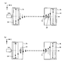
- FIG. 5 is a diagram for explaining a different configuration example of the magnetic quality detection device 1.
- the magnetic quality detection device 1 is a separate unit composed of a unit 2a including a magnet 30 and a unit 2b including a magnet 40, a first magnetic sensor 10, and a second magnetic sensor 20. It may be a configuration. Further, as described with reference to FIGS. 1 and 2, the second magnetic sensor 20 may be arranged at a position different from the arrangement position of the first magnetic sensor 10 in the magnetic field, as shown in FIG. In addition, the magnet 30 and the second magnetic sensor 20 may be included in one unit 3a, and the magnet 40 and the first magnetic sensor 40 may be included in the other unit 3b. In the configuration shown in FIG.
- the magnetic field strength gradually decreases from the position of the magnet 30 in the units 2a and 3a on the upstream side in the transport direction from the first magnetic sensor 10 in the transport direction. Thus, it becomes 0 (zero) between the units (unit 2a and unit 2b, unit 3a and unit 3b). Then, after a zero magnetic field with a magnetic field strength of 0 (zero) continues, a reverse magnetic field is generated again, and this magnetic field strength gradually increases as it approaches the units 2b and 3b on the downstream side in the transport direction. To do.
- the second magnetic sensor 20 is disposed above the magnet 40, so that the position of the magnet 40 on the downstream side is lowered below the magnet 30 on the upstream side in the transport direction.
- the arrangement position of the magnets 30 and 40 is not limited to this. Further, the type of magnet, magnetic force, shape, etc. are not particularly limited.
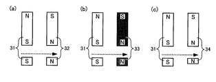
- FIG. 6 is a diagram illustrating an example in which the arrangement positions and magnetic forces of the two magnets 30 and 40 used in the magnetic quality detection device 1 are different.
- the figure which looked at the magnet from upper direction Z-axis positive direction side
- the figure which looked at from the front Y-axis positive direction side
- the arrangement positions of the two magnets 31 and 32 in the height direction Z-axis direction
- the second magnetic sensor 20 may be disposed on the side of the magnets 31 and 32.
- the magnetic force, kind, shape, etc. of two magnets may differ.
- the material of the two magnets 31 and 33 may be changed so that the magnetic force of one magnet 33 may be weaker than the magnetic force of the other magnet 31.
- the shape of the magnet as viewed from the front may be different as shown in FIG.
- FIG. 7 is a diagram illustrating an example in which the shape of the magnet used in the magnetic quality detection device 1 is different.
- the figure which looked at the magnet from upper direction Z-axis positive direction side
- the figure which looked from the side X-axis positive direction side
- 2 shows an example in which the magnets 30 and 40 have a rectangular parallelepiped shape.
- the two magnets 35a and 35b are formed in a U-shaped side yoke.
- the shape attached to the both end surfaces of 71 may be sufficient.
- the two magnets 36 a and 36 b may be attached to the inner surfaces of both end portions of the side U-shaped yoke 72.
- FIG. 8 is a diagram illustrating an example in which the configuration of the magnet used in the magnetic quality detection device 1 is different.
- four magnets are used as two sets of magnets.
- a magnetic field similar to that in FIGS. 1 and 2 can be generated.
- each magnet may be mounted on a flat yoke 73, or each magnet may be placed on a nonmagnetic material 83 as shown in FIG. 8 (b). It is also possible to use a fixed number.
- a magnetic field is generated in a direction perpendicular to the conveyance direction of the paper sheet 100 and parallel to the conveyance surface. After the magnetic field intensity of the magnetic field gradually decreases and reaches 0 (zero), the direction of the magnetic field is reversed. If the magnetic field strength can be increased again, the type, magnetic force, shape, number, arrangement position, presence / absence of the yoke, etc. of the magnet are not particularly limited, and a magnet unit can be formed using various magnets.
- FIG. 9 is a diagram for explaining a different configuration example of the magnetic quality detection device.
- FIG. 9A shows a view of the magnetic quality detection device 11 viewed from the front (Y axis positive direction side), and
- FIG. 9B shows a view of the magnetic quality detection device 11 viewed from below (Z axis negative direction side).
- FIG. 9C shows a saturation magnetization curve of the magnetic ink to be detected.
- 9D shows a paper sheet 100 containing a plurality of types of magnetic ink as an example of a detection target
- FIGS. 9E and 9F show magnetic materials contained in the paper sheet 100.
- FIG. The detection signal obtained by the magnetic quality detection device 11 when detected is shown.
- the magnetic quality detection device 11 is installed above the conveyance path through which the paper sheet 100 is conveyed, the arrangement of the magnets 30 and 40, and the first magnetic sensor 10. And the arrangement position of the 2nd magnetic sensor differs from the magnetic quality detection apparatus 1 shown in FIG.
- the magnets 30 and 40 are arranged in an inclined state so as to form an angle with respect to the transport direction (X axis) of the paper sheet 100 when viewed from the front (Y axis positive direction side). ing. Further, the two magnets 30 and 40 have different positions in the height direction (Z-axis direction), and the magnet 30 at the magnetization position P4 on the upstream side in the transport direction is disposed at a position close to the transport path, and is on the downstream side. The magnet 40 is disposed at a position further away from the conveyance path in the height direction than the magnet 30 on the upstream side.
- the first magnetic sensor 10 has a magnetization strength of 0 (zero) when the magnetic ink having a coercive force 220 Oe magnetized in the saturated magnetization state at the position P4 is conveyed. It arrange
- the second magnetic sensor 20 is disposed at a position P6 on the downstream side in the transport direction of the first magnetic sensor 10 in the magnetic field.
- FIG. 9D a paper sheet 100 in which a magnetic pattern composed of four straight lines is formed with magnetic inks having coercive forces 56, 90, 220, 300, and 350 Oe, respectively.
- the first magnetic sensor 10 obtains the detection signal shown in FIG. 5E
- the second magnetic sensor 20 produces the detection signal shown in FIG. can get.
- FIGS. 9D to 9F the magnetic patterns and the detection signals from the respective sensors obtained from the magnetic patterns are shown aligned with each other.
- a magnetic field is generated and the first magnetic sensor 10 and the second magnetic sensor 20 are arranged, so that the sensors shown in FIGS. 9E and 9F are detected.
- a signal is obtained.
- the detection signal corresponding to the magnetic ink having a coercive force of 220 Oe is substantially 0 (zero)
- the coercive force is 56 Oe smaller than 220 Oe and
- 90 Oe magnetic ink as shown in FIG. 9 (e), after swinging from the substantially 0 (zero) state once to the minus side, it swings to the plus side, and the plus side corresponds to four magnetic patterns corresponding to the four magnetic patterns.
- a signal of approximately 0 (zero) is once shifted to the minus side and then added. Swing to the side and show 4 peaks on the plus side.
- a detection signal having the same phase as that of the first magnetic sensor 10 is obtained in the magnetic inks having coercive forces 56 Oe and 90 Oe, and a detection signal having a phase opposite to that of the first magnetic sensor 10 is obtained in the magnetic ink having coercive forces 300 Oe and 350 Oe.
- the second magnetic sensor 20 detects magnetism while the output value from the first magnetic sensor 10 is substantially 0 (zero). In this case, it can be determined that the magnetic ink has a coercive force of 220 Oe.
- the output from the first magnetic sensor 10 and the output from the second magnetic sensor 20 are signals having the same phase, it is determined that the magnetic ink has a coercive force smaller than 220 Oe, and the signals have opposite phases. It can be determined that the magnetic ink has a coercive force larger than 220 Oe.
- the magnetic quality detection devices 1 and 11 are arranged only on one side below or above the conveyance path for conveying the paper sheet 100, the size of the device is reduced. Manufacturing costs can also be reduced.
- the assembly work to the paper sheet processing apparatus becomes easy, and a new magnetic material is added to the conveyance path of the existing paper sheet processing apparatus. It becomes easy to additionally use the detection devices 1 and 11.
- the magnetic quality detection devices 1 and 11 are arranged on one side above or below the conveyance path, a conveyance roller or the like constituting a part of the conveyance mechanism is arranged on the other side of the conveyance path, and the paper sheet 100 Can be transported in a stable state. If the paper sheet 100 is pressed against the transport path by a transport roller or the like, the magnetic substance contained in the paper sheet 100 is not formed without a gap between the magnetic quality detection devices 1 and 11 and the paper sheet 100. Magnetism can be detected stably.
- the present invention is a useful technique for detecting magnetic ink on a valuable medium.
Landscapes
- General Physics & Mathematics (AREA)
- Physics & Mathematics (AREA)
- Chemical & Material Sciences (AREA)
- General Health & Medical Sciences (AREA)
- Health & Medical Sciences (AREA)
- Life Sciences & Earth Sciences (AREA)
- Chemical Kinetics & Catalysis (AREA)
- Biochemistry (AREA)
- Analytical Chemistry (AREA)
- Electrochemistry (AREA)
- Immunology (AREA)
- Pathology (AREA)
- Inspection Of Paper Currency And Valuable Securities (AREA)
- Measuring Magnetic Variables (AREA)
- Investigating Or Analyzing Materials By The Use Of Magnetic Means (AREA)
Abstract
Description
10 第1磁気センサ
10a~10f 磁気センサ
20 第2磁気センサ
30~38、40 磁石
70~73 ヨーク
83 非磁性体
100 紙葉類
Claims (14)
- 搬送路を搬送される紙葉類に含まれる磁性体の磁気質を検出する磁気質検出装置であって、
前記搬送路を搬送される紙葉類の搬送方向と垂直かつ前記紙葉類の搬送面と平行な向きの磁界で磁界強度が前記搬送方向に進むに連れて減少してゼロに達した後に磁界の向きを逆向きにして再び磁界強度が増加する磁界を発生させる磁石ユニットと、
前記磁石ユニットによる磁界内で、それぞれが磁界強度の異なる位置に配置されて、前記搬送路を搬送される紙葉類の磁気質を検出する複数の磁気センサと
を備え、
磁性体を検出した際の前記複数の磁気センサの出力信号に基づいて紙葉類に含まれる磁性体の磁気質を検出する
ことを特徴とする磁気質検出装置。 - 真の紙葉類に含まれる磁性体を検出した際の前記複数の磁気センサの内の所定の磁気センサの出力値がゼロとなる場合には、
前記複数の磁気センサのうち、前記所定の磁気センサ以外の他の磁気センサの出力値が0以外であることを条件に、所定の磁性質を有する磁性体を含むと判断し、磁気を検出した紙葉類を真の紙葉類であると判定する真偽判定部を備えたことを特徴とする請求項1に記載の磁気質検出装置。 - 真の紙葉類に含まれる磁性体を検出した際の前記複数の磁気センサの出力値が略ゼロとなる前記磁気センサが無い場合、
前記複数の磁気センサのうちの所定の隣り合う2つの磁気センサの出力の位相が逆になっていることにより、所定の磁性質を有する磁性体を含むと判断し、磁気を検出した紙葉類を真の紙葉類であると判定する真偽判定部
を備えたことを特徴とする請求項1に記載の磁気質検出装置。 - 前記磁石ユニットによる磁界内で、所定の保磁力を有する磁性体の磁化特性に基づいて設定された位置で前記搬送路を搬送される紙葉類の磁気質を検出する第1磁気センサと、
前記第1磁気センサと異なる位置で前記搬送路を搬送される紙葉類の磁気質を検出する第2磁気センサと
を備えることを特徴とする請求項1に記載の磁気質検出装置。 - 前記磁石ユニットは、少なくとも、
紙葉類の搬送方向と垂直かつ前記紙葉類の搬送面と平行な方向に磁界を発生させる第1磁石と、
前記第1磁石より搬送方向下流側で前記第1磁石による磁界と逆向きの磁界を発生させる第2磁石と
を含むことを特徴とする請求項1~4のいずれか1項に記載の磁気質検出装置。 - 前記第1磁気センサは、所定の保磁力を有する磁性体の磁化特性に基づいて、前記磁界内で飽和磁化状態に着磁された前記磁性体が前記搬送方向に搬送されて磁化強度がゼロとなる位置に配置されることを特徴とする請求項3に記載の磁気質検出装置。
- 前記第1磁気センサにより磁気を検出せずかつ前記第2磁気センサにより磁気を検出した場合に、所定の保磁力を有する前記磁性体であると判定することを特徴とする請求項6に記載の磁気質検出装置。
- 前記第1磁気センサによる磁気の検出信号及び前記第2磁気センサによる磁気の検出信号の位相に基づいて、検出した磁性体の保磁力を判定することを特徴とする請求項6又は7に記載の磁気質検出装置。
- 前記磁石ユニットによる磁界は前記第1磁気センサよりも搬送方向上流側で検出対象とする磁性体を飽和磁化状態とする磁界強度を有することを特徴とする請求項1~8のいずれか1項に記載の磁気質検出装置。
- 前記磁石ユニットによる磁界は、前記搬送方向に進むに連れて磁界強度が徐々に減少してゼロになった後に、前記搬送方向にゼロ磁界が続き、その後に磁界の向きを逆向きにして再び磁界強度が増加することを特徴とする請求項1~9のいずれか1項に記載の磁気質検出装置。
- 前記第1センサが配置された位置の磁界強度を変更するための調整機構をさらに備えることを特徴とする請求項1~10のいずれか1項に記載の磁気質検出装置。
- 前記第1磁気センサ及び前記第2磁気センサは、着磁された磁性材料が前記磁界内を通過することによる磁束密度の変化を検出するセンサであることを特徴とする請求項1~11のいずれか1項に記載の磁気質検出装置。
- 前記第1磁気センサは、各々が磁界強度の異なる位置に配置された複数の磁気センサの中から、検出対象とする磁性体が前記搬送路を搬送された際に得られる各磁気センサの出力に基づいて選択されたものであることを特徴とする請求項4~12のいずれか1項に記載の磁気質検出装置。
- 複数の前記磁気センサの中から、前記磁性体が搬送された際に、正の出力を示す磁気センサ及び該磁気センサの隣に配置されて負の出力を示す磁気センサを選択して、2つの前記磁気センサを前記第1磁気センサとして利用することを特徴とする請求項13に記載の磁気質検出装置。
Priority Applications (6)
| Application Number | Priority Date | Filing Date | Title |
|---|---|---|---|
| RU2015139840A RU2610341C1 (ru) | 2013-03-22 | 2013-03-22 | Устройство детектирования магнитного свойства |
| JP2015506514A JP5945627B2 (ja) | 2013-03-22 | 2013-03-22 | 磁気質検出装置 |
| PCT/JP2013/058353 WO2014147824A1 (ja) | 2013-03-22 | 2013-03-22 | 磁気質検出装置 |
| US14/778,143 US9595152B2 (en) | 2013-03-22 | 2013-03-22 | Magnetic property detection apparatus |
| CN201380073952.XA CN105026924B (zh) | 2013-03-22 | 2013-03-22 | 磁特性检测装置 |
| EP13879233.8A EP2977754A4 (en) | 2013-03-22 | 2013-03-22 | DEVICE FOR DETECTING MAGNETIC CHARACTERISTICS |
Applications Claiming Priority (1)
| Application Number | Priority Date | Filing Date | Title |
|---|---|---|---|
| PCT/JP2013/058353 WO2014147824A1 (ja) | 2013-03-22 | 2013-03-22 | 磁気質検出装置 |
Publications (1)
| Publication Number | Publication Date |
|---|---|
| WO2014147824A1 true WO2014147824A1 (ja) | 2014-09-25 |
Family
ID=51579553
Family Applications (1)
| Application Number | Title | Priority Date | Filing Date |
|---|---|---|---|
| PCT/JP2013/058353 WO2014147824A1 (ja) | 2013-03-22 | 2013-03-22 | 磁気質検出装置 |
Country Status (6)
| Country | Link |
|---|---|
| US (1) | US9595152B2 (ja) |
| EP (1) | EP2977754A4 (ja) |
| JP (1) | JP5945627B2 (ja) |
| CN (1) | CN105026924B (ja) |
| RU (1) | RU2610341C1 (ja) |
| WO (1) | WO2014147824A1 (ja) |
Cited By (5)
| Publication number | Priority date | Publication date | Assignee | Title |
|---|---|---|---|---|
| CN105093135A (zh) * | 2015-06-25 | 2015-11-25 | 无锡乐尔科技有限公司 | 磁头以及磁性介质的评价方法 |
| CN107148641A (zh) * | 2014-10-03 | 2017-09-08 | 三菱电机株式会社 | 图像读取装置 |
| WO2017191823A1 (ja) * | 2016-05-06 | 2017-11-09 | 三菱電機株式会社 | 磁気センサ装置 |
| US11177063B2 (en) | 2017-08-11 | 2021-11-16 | Phoenix Contact Gmbh & Co. Kg | Method for magnetising at least two magnets having different magnetic coercivity |
| JP7431170B2 (ja) | 2018-03-27 | 2024-02-14 | イリノイ トゥール ワークス インコーポレイティド | 真のガウス磁気測定を用いる磁気検査装置 |
Families Citing this family (11)
| Publication number | Priority date | Publication date | Assignee | Title |
|---|---|---|---|---|
| DE102011120972A1 (de) * | 2011-12-13 | 2013-06-13 | Giesecke & Devrient Gmbh | Verfahren und Vorrichtung zur Prüfung von Wertdokumenten |
| JP6049864B2 (ja) * | 2013-04-09 | 2016-12-21 | グローリー株式会社 | 磁気質判別装置及び磁気質判別方法 |
| JP6619992B2 (ja) * | 2015-11-13 | 2019-12-11 | グローリー株式会社 | 磁気検出装置 |
| CN105548923A (zh) * | 2015-12-30 | 2016-05-04 | 河北工业大学 | 一种二维高频旋转磁特性传感器件 |
| KR101842133B1 (ko) * | 2016-05-30 | 2018-03-26 | 한국표준과학연구원 | 임프린팅 방식을 이용한 자화상태 제어 방법 |
| CN107643489B (zh) * | 2016-07-22 | 2024-01-09 | 苏州宝时得电动工具有限公司 | 电能存储装置、电动工具及其控制方法 |
| CN106353701A (zh) * | 2016-08-24 | 2017-01-25 | 明光万佳联众电子有限公司 | 一种自动测恒定磁场机 |
| EP3503047B1 (de) * | 2017-12-22 | 2021-01-27 | CI Tech Sensors AG | Vorrichtung zum nachweis eines magnetischen sicherheitsmerkmals eines wertdokuments und verfahren zur messwertkompensation für den nachweis eines magnetischen sicherheitsmerkmals eines wertdokuments |
| JPWO2020013123A1 (ja) * | 2018-07-08 | 2021-08-05 | 株式会社 マトリックス細胞研究所 | 磁性体検出装置 |
| CN110738785A (zh) * | 2019-09-19 | 2020-01-31 | 中钞特种防伪科技有限公司 | 用于磁性防伪元件的检测方法及设备 |
| CN114582063A (zh) * | 2022-03-18 | 2022-06-03 | 苏州日宝科技有限责任公司 | 一种纸币清分鉴伪设备、方法、终端及存储介质 |
Citations (4)
| Publication number | Priority date | Publication date | Assignee | Title |
|---|---|---|---|---|
| JPH04364498A (ja) * | 1991-06-12 | 1992-12-16 | Glory Ltd | 磁気質検出方法およびこれを用いた磁気質検出装置 |
| JP3283931B2 (ja) * | 1992-12-11 | 2002-05-20 | グローリー工業株式会社 | 磁気質検出装置 |
| JP2006293575A (ja) * | 2005-04-08 | 2006-10-26 | Fuji Electric Retail Systems Co Ltd | 紙葉類の識別装置及び識別方法 |
| WO2010052797A1 (ja) | 2008-11-10 | 2010-05-14 | グローリー株式会社 | 磁気質検出装置 |
Family Cites Families (14)
| Publication number | Priority date | Publication date | Assignee | Title |
|---|---|---|---|---|
| JP3283930B2 (ja) | 1992-12-11 | 2002-05-20 | グローリー工業株式会社 | 磁気質検知方法 |
| US5451759A (en) * | 1993-06-24 | 1995-09-19 | Nhk Spring Co., Ltd. | Using high-permeability magnetic elements randomly scattered in the objects |
| US5644228A (en) * | 1993-08-31 | 1997-07-01 | Eastman Kodak Company | Permanent magnet assembly with MR and DC compensating bias |
| US5552589A (en) * | 1993-08-31 | 1996-09-03 | Eastman Kodak Company | Permanent magnet assembly with MR element for detection/authentication of magnetic documents |
| DE19501245A1 (de) * | 1995-01-17 | 1996-07-18 | Giesecke & Devrient Gmbh | Vorrichtung zur Prüfung magnetischer Eigenschaften von Blattgut, wie z. B. Banknoten oder Wertpapiere |
| JP2005129009A (ja) * | 2003-09-30 | 2005-05-19 | Fuji Electric Retail Systems Co Ltd | 紙葉類鑑別装置及び紙葉類鑑別方法 |
| DE102004049999A1 (de) * | 2004-10-14 | 2006-04-20 | Giesecke & Devrient Gmbh | Sicherheitselement |
| ITMI20080053A1 (it) | 2008-01-15 | 2009-07-16 | Fabriano Securities Srl | Elemento di sicurezza, particolarmente per banconote, carte di sicurezza e simili, avente caratteristiche anti-contraffazione. |
| ITMI20080261A1 (it) | 2008-02-19 | 2009-08-20 | Fabriano Securities Srl | Sensore di lettura di banconote, carte di sicurezza e simili, contenenti almeno un elemento di sicurezza. |
| DE102008061507A1 (de) * | 2008-12-10 | 2010-06-17 | Giesecke & Devrient Gmbh | Magnetsensor zur Prüfung von Wertdokumenten |
| DE102009039588A1 (de) * | 2009-09-01 | 2011-03-03 | Giesecke & Devrient Gmbh | Verfahren und Vorrichtung zur Prüfung von Wertdokumenten |
| KR101427543B1 (ko) * | 2010-07-30 | 2014-08-07 | 미쓰비시덴키 가부시키가이샤 | 자성체 검출 장치 |
| JP5867235B2 (ja) * | 2011-05-16 | 2016-02-24 | 三菱電機株式会社 | 磁気センサ装置 |
| JP6180305B2 (ja) * | 2013-12-03 | 2017-08-16 | 株式会社日立製作所 | 通信装置、通信方法及び通信システム |
-
2013
- 2013-03-22 US US14/778,143 patent/US9595152B2/en active Active
- 2013-03-22 CN CN201380073952.XA patent/CN105026924B/zh active Active
- 2013-03-22 RU RU2015139840A patent/RU2610341C1/ru active
- 2013-03-22 JP JP2015506514A patent/JP5945627B2/ja active Active
- 2013-03-22 EP EP13879233.8A patent/EP2977754A4/en not_active Withdrawn
- 2013-03-22 WO PCT/JP2013/058353 patent/WO2014147824A1/ja active Application Filing
Patent Citations (4)
| Publication number | Priority date | Publication date | Assignee | Title |
|---|---|---|---|---|
| JPH04364498A (ja) * | 1991-06-12 | 1992-12-16 | Glory Ltd | 磁気質検出方法およびこれを用いた磁気質検出装置 |
| JP3283931B2 (ja) * | 1992-12-11 | 2002-05-20 | グローリー工業株式会社 | 磁気質検出装置 |
| JP2006293575A (ja) * | 2005-04-08 | 2006-10-26 | Fuji Electric Retail Systems Co Ltd | 紙葉類の識別装置及び識別方法 |
| WO2010052797A1 (ja) | 2008-11-10 | 2010-05-14 | グローリー株式会社 | 磁気質検出装置 |
Non-Patent Citations (1)
| Title |
|---|
| See also references of EP2977754A4 * |
Cited By (5)
| Publication number | Priority date | Publication date | Assignee | Title |
|---|---|---|---|---|
| CN107148641A (zh) * | 2014-10-03 | 2017-09-08 | 三菱电机株式会社 | 图像读取装置 |
| CN105093135A (zh) * | 2015-06-25 | 2015-11-25 | 无锡乐尔科技有限公司 | 磁头以及磁性介质的评价方法 |
| WO2017191823A1 (ja) * | 2016-05-06 | 2017-11-09 | 三菱電機株式会社 | 磁気センサ装置 |
| US11177063B2 (en) | 2017-08-11 | 2021-11-16 | Phoenix Contact Gmbh & Co. Kg | Method for magnetising at least two magnets having different magnetic coercivity |
| JP7431170B2 (ja) | 2018-03-27 | 2024-02-14 | イリノイ トゥール ワークス インコーポレイティド | 真のガウス磁気測定を用いる磁気検査装置 |
Also Published As
| Publication number | Publication date |
|---|---|
| JPWO2014147824A1 (ja) | 2017-02-16 |
| US20160071350A1 (en) | 2016-03-10 |
| EP2977754A1 (en) | 2016-01-27 |
| CN105026924B (zh) | 2019-01-08 |
| CN105026924A (zh) | 2015-11-04 |
| US9595152B2 (en) | 2017-03-14 |
| EP2977754A4 (en) | 2016-12-21 |
| JP5945627B2 (ja) | 2016-07-05 |
| RU2610341C1 (ru) | 2017-02-09 |
Similar Documents
| Publication | Publication Date | Title |
|---|---|---|
| JP5945627B2 (ja) | 磁気質検出装置 | |
| JP5127440B2 (ja) | 磁気パターン検出装置 | |
| US20110233277A1 (en) | Magnetic sensor for checking value document | |
| JP5889697B2 (ja) | 紙葉類磁性評価装置及び紙葉類磁性評価方法 | |
| KR20140051385A (ko) | 측정 장치의 주위 환경들의 자기 특성들을 측정하기 위한 측정 장치 | |
| JP6300908B2 (ja) | 磁気センサ装置 | |
| WO2014168180A1 (ja) | 磁気質判別装置及び磁気質判別方法 | |
| US10001533B2 (en) | Magnetic property determination apparatus and magnetic property determination method | |
| WO2016170885A1 (ja) | 磁気センサ装置 | |
| JP2007226674A (ja) | 紙葉類識別センサ | |
| US10222431B2 (en) | Measuring device with pre-magnetizing magnet | |
| US10008064B2 (en) | Measuring device for measuring magnetic properties of the surroundings of the measuring device | |
| WO2016170887A1 (ja) | 磁気センサ装置 | |
| JPH04364498A (ja) | 磁気質検出方法およびこれを用いた磁気質検出装置 | |
| JP2006293574A (ja) | 紙葉類の識別装置、識別方法及び磁気特性検出装置 | |
| JP2014203396A (ja) | 磁気質判別装置及び磁気質判別方法 | |
| WO2021199757A1 (ja) | 磁気センサ装置 | |
| JP4771738B2 (ja) | 紙葉類識別装置および紙葉類識別用磁気センサ | |
| JP4794553B2 (ja) | 磁気量検出センサ、磁気量検出センサ装置、および紙葉類識別装置 | |
| WO2021024758A1 (ja) | 磁気センサ装置 | |
| JP2005234626A (ja) | 紙葉類識別センサ及び紙葉類識別装置 | |
| JP2019179435A (ja) | 磁気識別センサおよび磁気識別装置 |
Legal Events
| Date | Code | Title | Description |
|---|---|---|---|
| WWE | Wipo information: entry into national phase |
Ref document number: 201380073952.X Country of ref document: CN |
|
| 121 | Ep: the epo has been informed by wipo that ep was designated in this application |
Ref document number: 13879233 Country of ref document: EP Kind code of ref document: A1 |
|
| WWE | Wipo information: entry into national phase |
Ref document number: 2013879233 Country of ref document: EP |
|
| ENP | Entry into the national phase |
Ref document number: 2015506514 Country of ref document: JP Kind code of ref document: A |
|
| ENP | Entry into the national phase |
Ref document number: 2015139840 Country of ref document: RU Kind code of ref document: A |
|
| WWE | Wipo information: entry into national phase |
Ref document number: 14778143 Country of ref document: US |
|
| NENP | Non-entry into the national phase |
Ref country code: DE |