WO2014147659A1 - 界磁制御装置、界磁制御方法およびこれらを用いた同期回転機 - Google Patents
界磁制御装置、界磁制御方法およびこれらを用いた同期回転機 Download PDFInfo
- Publication number
- WO2014147659A1 WO2014147659A1 PCT/JP2013/001843 JP2013001843W WO2014147659A1 WO 2014147659 A1 WO2014147659 A1 WO 2014147659A1 JP 2013001843 W JP2013001843 W JP 2013001843W WO 2014147659 A1 WO2014147659 A1 WO 2014147659A1
- Authority
- WO
- WIPO (PCT)
- Prior art keywords
- field
- field current
- request value
- rotating machine
- unit
- Prior art date
- Legal status (The legal status is an assumption and is not a legal conclusion. Google has not performed a legal analysis and makes no representation as to the accuracy of the status listed.)
- Ceased
Links
Images






Classifications
-
- H—ELECTRICITY
- H02—GENERATION; CONVERSION OR DISTRIBUTION OF ELECTRIC POWER
- H02P—CONTROL OR REGULATION OF ELECTRIC MOTORS, ELECTRIC GENERATORS OR DYNAMO-ELECTRIC CONVERTERS; CONTROLLING TRANSFORMERS, REACTORS OR CHOKE COILS
- H02P6/00—Arrangements for controlling synchronous motors or other dynamo-electric motors using electronic commutation dependent on the rotor position; Electronic commutators therefor
- H02P6/24—Arrangements for stopping
-
- H—ELECTRICITY
- H02—GENERATION; CONVERSION OR DISTRIBUTION OF ELECTRIC POWER
- H02P—CONTROL OR REGULATION OF ELECTRIC MOTORS, ELECTRIC GENERATORS OR DYNAMO-ELECTRIC CONVERTERS; CONTROLLING TRANSFORMERS, REACTORS OR CHOKE COILS
- H02P6/00—Arrangements for controlling synchronous motors or other dynamo-electric motors using electronic commutation dependent on the rotor position; Electronic commutators therefor
- H02P6/34—Modelling or simulation for control purposes
-
- H—ELECTRICITY
- H02—GENERATION; CONVERSION OR DISTRIBUTION OF ELECTRIC POWER
- H02K—DYNAMO-ELECTRIC MACHINES
- H02K15/00—Processes or apparatus specially adapted for manufacturing, assembling, maintaining or repairing of dynamo-electric machines
- H02K15/02—Processes or apparatus specially adapted for manufacturing, assembling, maintaining or repairing of dynamo-electric machines of stator or rotor bodies
-
- H—ELECTRICITY
- H02—GENERATION; CONVERSION OR DISTRIBUTION OF ELECTRIC POWER
- H02K—DYNAMO-ELECTRIC MACHINES
- H02K3/00—Details of windings
- H02K3/04—Windings characterised by the conductor shape, form or construction, e.g. with bar conductors
- H02K3/18—Windings for salient poles
-
- H—ELECTRICITY
- H02—GENERATION; CONVERSION OR DISTRIBUTION OF ELECTRIC POWER
- H02P—CONTROL OR REGULATION OF ELECTRIC MOTORS, ELECTRIC GENERATORS OR DYNAMO-ELECTRIC CONVERTERS; CONTROLLING TRANSFORMERS, REACTORS OR CHOKE COILS
- H02P23/00—Arrangements or methods for the control of AC motors characterised by a control method other than vector control
- H02P23/14—Estimation or adaptation of motor parameters, e.g. rotor time constant, flux, speed, current or voltage
-
- H—ELECTRICITY
- H02—GENERATION; CONVERSION OR DISTRIBUTION OF ELECTRIC POWER
- H02P—CONTROL OR REGULATION OF ELECTRIC MOTORS, ELECTRIC GENERATORS OR DYNAMO-ELECTRIC CONVERTERS; CONTROLLING TRANSFORMERS, REACTORS OR CHOKE COILS
- H02P25/00—Arrangements or methods for the control of AC motors characterised by the kind of AC motor or by structural details
- H02P25/02—Arrangements or methods for the control of AC motors characterised by the kind of AC motor or by structural details characterised by the kind of motor
- H02P25/08—Reluctance motors
-
- H—ELECTRICITY
- H02—GENERATION; CONVERSION OR DISTRIBUTION OF ELECTRIC POWER
- H02P—CONTROL OR REGULATION OF ELECTRIC MOTORS, ELECTRIC GENERATORS OR DYNAMO-ELECTRIC CONVERTERS; CONTROLLING TRANSFORMERS, REACTORS OR CHOKE COILS
- H02P9/00—Arrangements for controlling electric generators for the purpose of obtaining a desired output
- H02P9/14—Arrangements for controlling electric generators for the purpose of obtaining a desired output by variation of field
- H02P9/26—Arrangements for controlling electric generators for the purpose of obtaining a desired output by variation of field using discharge tubes or semiconductor devices
-
- H—ELECTRICITY
- H02—GENERATION; CONVERSION OR DISTRIBUTION OF ELECTRIC POWER
- H02P—CONTROL OR REGULATION OF ELECTRIC MOTORS, ELECTRIC GENERATORS OR DYNAMO-ELECTRIC CONVERTERS; CONTROLLING TRANSFORMERS, REACTORS OR CHOKE COILS
- H02P9/00—Arrangements for controlling electric generators for the purpose of obtaining a desired output
- H02P9/14—Arrangements for controlling electric generators for the purpose of obtaining a desired output by variation of field
- H02P9/26—Arrangements for controlling electric generators for the purpose of obtaining a desired output by variation of field using discharge tubes or semiconductor devices
- H02P9/30—Arrangements for controlling electric generators for the purpose of obtaining a desired output by variation of field using discharge tubes or semiconductor devices using semiconductor devices
- H02P9/305—Arrangements for controlling electric generators for the purpose of obtaining a desired output by variation of field using discharge tubes or semiconductor devices using semiconductor devices controlling voltage
-
- G—PHYSICS
- G01—MEASURING; TESTING
- G01R—MEASURING ELECTRIC VARIABLES; MEASURING MAGNETIC VARIABLES
- G01R31/00—Arrangements for testing electric properties; Arrangements for locating electric faults; Arrangements for electrical testing characterised by what is being tested not provided for elsewhere
- G01R31/34—Testing dynamo-electric machines
- G01R31/343—Testing dynamo-electric machines in operation
-
- H—ELECTRICITY
- H02—GENERATION; CONVERSION OR DISTRIBUTION OF ELECTRIC POWER
- H02P—CONTROL OR REGULATION OF ELECTRIC MOTORS, ELECTRIC GENERATORS OR DYNAMO-ELECTRIC CONVERTERS; CONTROLLING TRANSFORMERS, REACTORS OR CHOKE COILS
- H02P2103/00—Controlling arrangements characterised by the type of generator
- H02P2103/20—Controlling arrangements characterised by the type of generator of the synchronous type
Definitions
- the present invention relates to a field control device for a synchronous rotating machine, a field control method, and a synchronous rotating machine using these.
- a large-capacity rotating electrical machine requires a load test apparatus of a considerable scale including a power supply facility and a load facility in order to perform an actual load test.
- the characteristics of the rotating electrical machine can be predicted prior to the field test, for example, the desired operating state of the rotating electrical machine can be realized by reflecting the characteristics in the field control.
- the present invention has been made to solve the above-described problems, and has an object to predict the characteristics of a synchronous rotating machine prior to an on-site test and enable field control reflecting the characteristics.
- the present invention provides a field control device for a synchronous rotating machine having an armature winding and a field winding, and a final control amount request that is a required value of a final control amount of the synchronous rotating machine.
- a target operating condition input unit that accepts a target operating condition request value including a value as an input, and a final control amount feedback value of the synchronous rotating machine from the final control amount request value input by the target operating condition input unit.
- a first subtraction unit that subtracts and outputs a final control amount deviation; a final control amount control calculation unit that receives the final control amount deviation from the first subtraction unit as an input and outputs a field current correction request value; , Based on the operation condition request value input at the target operation condition input unit, a preceding calculation unit that outputs a field current advance request value, the field current correction request value and the field current advance request value Add to the field An adder that outputs a set value; a second subtractor that outputs a field current deviation by subtracting a field current value flowing through the field winding from the field current set value; and A field current adjusting device that adjusts the field current based on the dependence current data storage unit that stores a dependence characteristic estimated based on a result of a no-load test of the synchronous rotating machine; A circuit calculation unit that performs a circuit calculation using the dependency characteristics based on the operation condition request value input by the target operation condition input unit and outputs a field current preceding request value.
- the present invention is a field control method for a synchronous rotating machine having an armature winding and a field winding, and a preliminary step for controlling the synchronous rotating machine, and an operating condition request after the preliminary step
- the present invention is a synchronous rotating machine comprising an armature winding, a field winding, and a field control device, wherein the field control device is a target including a final control amount requirement value of the synchronous rotating machine.
- a target operating condition input unit that receives the operating condition request value as an input, and a final control amount by subtracting a final control amount feedback value of the synchronous rotating machine from the final control amount request value output from the target operating condition input unit.
- a first subtraction unit that outputs a deviation
- a final control amount control calculation unit that receives the final control amount deviation from the first subtraction unit as an input and outputs a field current correction request value
- the target operating condition Based on the operating condition request value input at the input unit, a preceding calculation unit that outputs a field current preceding request value, and adding the field current correction request value and the field current preceding request value to add a field current Output current setting value
- a calculation unit a second subtraction unit that outputs a field current deviation by subtracting a field current value flowing through the field winding from the field current set value; and a field current based on the field current deviation.
- a field current adjustment device that adjusts the dependence current data storage unit that stores a dependence characteristic estimated based on a result of a no-load test of the synchronous rotating machine, and the target operation And a circuit calculation unit that performs circuit calculation using the dependence characteristic based on the operation condition request value input by a condition input unit and outputs a field current preceding request value.
- the present invention it is possible to predict the characteristics of the synchronous rotating machine prior to the field test, and to perform field control reflecting the characteristics.
- FIG. 1 is a block diagram showing the configuration of the synchronous rotating machine according to the first embodiment.
- the synchronous rotating machine 500 includes a rotating machine main body 450 and a field control device 400. Details of the configuration of the synchronous rotating machine 500 will be described later.
- FIG. 2 is a schematic partial cross-sectional view of a quarter of the rotating machine body of the synchronous rotating machine according to the first embodiment.
- FIG. 3 is a connection diagram of field windings of the synchronous rotating machine according to the first embodiment.
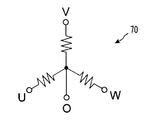
- FIG. 4 is a connection diagram of armature windings of the synchronous rotating machine according to the first embodiment.
- a reluctance type multi-phase synchronous rotating machine (hereinafter simply referred to as “rotating machine main body”) 450 is, for example, a three-phase synchronous generator.
- the rotating machine main body 450 includes the rotor 10 and the stator 40 inside a housing (not shown).
- the rotor 10 is a salient pole rotor in which the field winding 60 is not wound, and has a main shaft 20 and a rotor core 30.
- the main shaft 20 extends coaxially with the rotating shaft, and is rotatably supported by a bearing (not shown) provided in the housing.
- the rotor core 30 is formed by laminating a plurality of (many) silicon steel plates in the direction of the rotation axis, and is fixed to the outer periphery of the main shaft 20 and extends coaxially with the rotation axis.
- On the outer periphery of the rotor core 30 are formed 40 salient pole portions 32 having convex shapes (for example, a substantially rectangular cross section) arranged at equal intervals in the circumferential direction. That is, a concave groove 34 is formed between adjacent salient pole portions 32.
- the rotor core 30 has a length in the direction of the rotation axis of 50 mm and an outer radius (a distance from the center of the rotation axis to the tip surface of the salient pole portion 32) of 255 mm.
- the stator 40 has a stator core 50, a multi-pole field winding 60, and a multi-pole three-phase armature winding 70.
- the stator core 50 is formed by laminating a large number of silicon steel plates in the direction of the rotation axis, and is arranged on the outer periphery of the rotor 10 with a gap (air gap) from the rotor 10.
- a gap air gap
- 48 teeth 52 having a convex shape (for example, a substantially rectangular cross section) arranged at equal intervals in the circumferential direction are formed on the inner periphery of the stator core 50. That is, a slot 54 is formed between adjacent teeth 52.
- the stator core 50 has a length in the rotation axis direction of 50 mm, an outer diameter of 315 mm, and a radial thickness (distance from the tip surface of the teeth 52 to the outer peripheral surface of the stator core 50) of 59. .5mm.
- the stator core 50 is disposed such that the distance of the air gap (the distance from the tip surface of the salient pole portion 32 to the tip surface of the tooth 52) is 0.5 mm.
- a conductive wire such as a copper wire is wound around 48 teeth 52 perpendicularly in the radial direction via an insulator.
- the field windings 60 wound around the adjacent teeth 52 are wound in opposite directions, and are connected in series as shown in FIGS. 2 and 3.
- a field current is supplied to the field winding 60 from a DC power source (not shown). Therefore, in the present embodiment, the number of poles p f of the field winding 60, and has a number and the same 48-pole teeth 52. The number of turns of the field winding 60 is 9216 turns.
- armature winding 70 In the three-phase armature winding 70, a conductor such as a copper wire is wound around 48 teeth 52 perpendicularly in a radial direction via an insulator.
- the three-phase armature winding 70 is wound so as to be insulated from the field winding 60 at a position radially inward from the field winding 60 and wound around the adjacent teeth 52.
- the armature windings 70 are wound in the same direction.
- the armature winding 70 is composed of three-phase (U-phase, V-phase, W-phase) windings that are Y-connected to each other, and is formed in the circumferential direction.
- the number of turns of the three-phase armature winding 70 is 528 for each phase.
- the number of turns and the number of poles of the field winding 60 and the armature winding 70 are examples, and are not limited to the above. Depending on the capacity of the synchronous rotating machine and the like, an appropriate number of turns and poles may be selected in design.
- the operation of the rotating machine main body 450 will be described using a generator as an example.
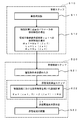
- FIG. 5 is a flowchart showing a part of the steps of the field control method for the synchronous rotating machine according to the first embodiment.
- step S10 first, a no-load test of the target rotating machine main body 450 is performed, and each characteristic data is collected (step S11).
- FIG. 6 is an equivalent circuit during the open test of the synchronous rotating machine according to the first embodiment.
- the synchronous rotating machine 500 (see FIG. 2) is operated with the load-side terminal open, and includes the induced electromotive force vector Eaf, the armature current vector Ia, and the armature winding 70 (see FIG. 2) of the rotating machine body 450.
- Characteristic data such as the inductance Ls of the child circuit and the resistance Rc of the equivalent iron loss are collected.
- FIG. 7 is an equivalent circuit during a short circuit test of the synchronous rotating machine according to the first embodiment.
- the rotating machine main body 450 With the load side terminal short-circuited, the rotating machine main body 450 (see FIG. 2) is operated, and the induced electromotive force vector Eaf, armature current vector Ia, field current If, and synchronous impedance of the rotating machine main body 450 are used.
- Characteristic data such as a certain synchronous inductance Ls, a mutual inductance Maf between the field winding and the armature winding, and a resistance Ra of the armature winding are collected.
- step S11 based on the data obtained in the no-load test, the dependence characteristic of the parameter necessary for the characteristic calculation in the equivalent circuit is derived (step S12).
- Parameters required for characteristic calculation include a synchronous inductance Ls, a mutual inductance Maf between the field winding and the armature winding, and a resistance Ra of the armature winding. Note that the following description can be similarly applied to parameters other than those necessary.
- each parameter is derived in the form of a characteristic function depending on the armature winding interlinkage magnetic flux number ⁇ af.
- the dependence characteristics of each parameter are expressed by the characteristic functions shown in the following equations (3) to (5) as a function of the armature winding interlinkage magnetic flux number ⁇ af.
- Maf Maf ( ⁇ af) (3)
- Ls Ls ( ⁇ af) (4)
- Rc Rc ( ⁇ af) (5)
- the specific forms of the functions represented by the expressions (3) to (5) may be in the form of expressions of analytical expressions. Alternatively, it may be stored as table data for discrete values of the armature winding linkage magnetic flux number ⁇ af and may be obtained by interpolating the value of the armature winding linkage magnetic flux number ⁇ af, for example. Specific contents of the expressions (3) to (5) are stored in the database.
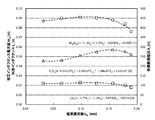
- FIG. 8 is a graph showing an example of dependency characteristics based on the no-load test result of the field controller 400 (FIG. 1) of the synchronous rotating machine according to the first embodiment.
- the horizontal axis is the armature winding interlinkage flux number ⁇ af [Wb]
- the left vertical axis is the synchronous inductance Ls [H] and the mutual inductance Maf [H]
- the right vertical axis is the equivalent iron loss resistance Rc [ ⁇ ]. is there.
- a field control step S20 for controlling the field of the target rotating machine main body 450 is entered.
- the operating condition request value is accepted as an input (step S21).
- the operation condition request value is a request value for the operation state including the main control amount, and in the case of the synchronous rotating machine 500 that is a synchronous generator, the generator voltage, the generator output, the rotation speed, the power factor, and the like.
- the main control amount is the generator voltage.
- step S21 a field current advance request value is calculated based on the operation condition request value received in step S21 (step S22).
- step S22 the dependence characteristic derived in step S12 and stored in the database is used.
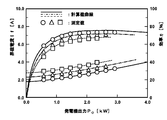
- FIG. 9 is a graph showing an example of comparison between the calculated value and the actually measured value using the dependence characteristic based on the no-load test result of the field control method for the synchronous rotating machine according to the first embodiment.
- the field current is adjusted based on the field current advance request value calculated in step S22 (step S23).
- the field current is adjusted by, for example, an AC excitation method, a DC excitation method, or a static excitation method.
- the field control device 400 includes a target operating condition input unit 110, a voltage control unit 120, a preceding calculation unit 130, and a field adjustment unit 140.
- the target operating condition input unit 110 accepts the target operating condition request value for the operating state including the main control amount, and outputs this target operating condition request value to the preceding calculation unit 130.
- a required voltage value which is a main control amount in the target operating condition required value, is output to the voltage control unit 120.
- the target operating condition input unit 110 holds the output to the preceding calculation unit 130 and the voltage control unit 120 unless the target operating condition request value is changed. Further, when the target operating condition request value is changed, the changed value is output to the preceding calculation unit 130 and the voltage control unit 120, and the value is held.
- This holding function may be provided not on the target operating condition input unit 110 side but on the preceding calculation unit 130 side and the voltage control unit 120 side, respectively.
- the target operating conditions are a generator voltage, a generator output, a rotational speed, and the like.
- the voltage control unit 120 includes a first subtraction unit 121, a voltage control calculation unit 122, and a voltage detection unit 123 in order to control the induced electromotive force of the synchronous rotating machine 500 to a predetermined value.
- the first subtraction unit 121 subtracts the generator voltage value fed back from the voltage detection unit 123 from the voltage request value input by the target operating condition input unit 110 and outputs a voltage deviation.
- the voltage control calculation unit 122 receives the voltage deviation from the first subtraction unit 121 and outputs a field current correction request value.
- the voltage control calculation unit 122 may be a simple gain, may further have an integral element, and may further have a differential element, and is determined in consideration of stability and controllability based on expected characteristics.
- the preceding calculation unit 130 outputs the field current preceding request value based on the operation condition request value input by the target operation condition input unit 110.
- the preceding calculation unit 130 includes a dependency characteristic data input unit 131, a dependency characteristic data storage unit 132, and a circuit calculation unit 133.
- the dependence characteristic data input unit 131 shows the dependence characteristics of the parameters such as the mutual inductance Maf, the synchronous inductance Ls, and the equivalent iron loss resistance Rc calculated based on the result of the no-load test on the armature winding interlinkage magnetic flux number ⁇ af. Accept as input from outside.
- the dependency characteristic data storage unit 132 stores dependency characteristic data, such as the mutual inductance Maf, the synchronous inductance Ls, and the equivalent iron loss resistance Rc, which are input from the dependency characteristic data input unit 131, on the armature winding linkage magnetic flux number ⁇ af. Database.
- the circuit calculation unit 133 accepts the operation condition request value output from the target operation condition input unit 110 as input, performs circuit calculation using the dependency characteristic data of each parameter stored in the dependency characteristic data storage unit 132, Outputs the field current precedence request value.
- the field adjusting unit 140 includes an adding unit 141, a second subtracting unit 142, a field current adjusting device 143, and a field current detecting unit 144.
- the adding unit 141 adds the field current correction request value from the voltage control calculation unit 122 and the field current preceding request value from the circuit calculation unit 133, and outputs a field current set value.
- the second subtraction unit 142 subtracts the field current value fed back from the field current detection unit 144 from the field current set value from the addition unit 141 and outputs a field current deviation.
- the field current adjusting device 143 adjusts the field current based on the field current deviation from the second subtracting unit 142.
- the target operation condition is input and the value is held.
- the target operating condition input unit 110 Based on the target operating conditions, the target operating condition input unit 110 outputs the target operating conditions, that is, the required values such as the generator voltage, the generator output, the rotation speed, and the power factor, to the circuit calculation unit 133 of the preceding calculation unit 130. ing.
- the target operating condition input unit 110 outputs the required value of the generator voltage, which is the main control amount, to the first subtracting unit 121 of the voltage control unit 120 based on the target operating condition.
- the circuit calculation unit 133 uses the dependency characteristic data stored in the dependency characteristic data storage unit 132 to calculate a field current If that satisfies the target operation condition from the target operation condition input unit 110, and The field current preceding request value is output to the field adjustment unit 140.
- the field current advance request value is added to the field current correction request value that is the output of the voltage control unit 120 in the addition unit 141 of the field adjustment unit 140 to become a field current set value, and is added to the field adjustment unit 140. Is output.
- the field adjustment unit 140 adjusts the field current of the rotating machine main body 450 so as to become the field current set value. That is, the second subtraction unit 142 subtracts the field current value fed back from the field current detection unit 144 from the field current set value, and outputs a field current deviation.
- the field current adjusting device 143 adjusts the value of the field current flowing through the field winding 60 based on the field current deviation.
- the voltage detection unit Since the generator voltage value fed back from 123 matches the required voltage value of the generator voltage output from the target operating condition input unit 110, the output of the first subtraction unit 121 becomes zero, and as a result, The field current correction request value that is the output of the voltage control calculation unit 122 is also zero.
- the first subtraction unit 121 outputs the difference between the generator voltage value fed back from the voltage detection unit 123 and the required voltage value of the generator voltage output from the target operating condition input unit 110, Based on this, the voltage control calculation unit 122 outputs the field current correction request value.
- FIG. 10 is a block diagram illustrating a configuration of the synchronous rotating machine according to the second embodiment.
- the field control device 400 in the present embodiment includes a power factor detection unit 223.
- the field control device 400 includes a power factor control calculation unit 222 instead of the voltage control calculation unit 122.
- the target operating condition input unit 110 outputs the power factor request value to the first subtraction unit 221.
- the first subtraction unit 221 subtracts the generator power factor value fed back from the power factor detection unit 223 from the power factor request value from the target operating condition input unit 110 and outputs a power factor deviation.
- the power factor control calculation unit 222 stores a phase characteristic curve (V curve) of the synchronous rotating machine 500 that has been evaluated and set in advance, that is, a dependence characteristic of the armature current Ia on the field current If.
- V curve phase characteristic curve
- the power factor control calculation unit 222 outputs a field current correction request value after calculation based on the power factor deviation.
- the power factor control calculation unit 222 may be a simple gain, may further have an integral element, and may further have a derivative element, and is determined in consideration of stability and controllability based on expected characteristics.
- the first subtraction unit 221 is used. Outputs the difference between the generator power factor value fed back from the power factor detection unit 223 and the power factor request value output from the target operating condition input unit 110, and based on this, the power factor control calculation unit 222 outputs the field Outputs the current correction request value.
- FIG. 11 is a block diagram showing the configuration of the synchronous rotating machine according to the third embodiment.
- This embodiment is a modification of the first embodiment.
- the synchronous rotating machine 500 in the present embodiment is a synchronous motor.
- the target operating condition in the case of a synchronous motor is, for example, torque.
- the main control amount is also torque.
- the field controller 400 includes an output detection unit 324 that detects the output of the synchronous rotating machine 500, a rotation number detection unit 325 that detects the rotation number, a torque calculation unit 323 that calculates torque from the output and the rotation number, and A torque control calculation unit 322 is included.
- the rotation speed is basically the rotation speed corresponding to the power supply frequency, and the rotation speed detection unit 325 is not necessarily provided.
- the target operating condition input unit 210 outputs a torque request value to the first subtraction unit 321.
- the first subtraction unit 321 subtracts the torque value calculated by the torque calculation unit 323 from the torque request value from the target operation condition input unit 210 and outputs a torque deviation.
- the torque control calculation unit 322 outputs a field current correction request value after calculation based on the torque deviation.
- the torque control calculation unit 322 may be a simple gain, may further have an integral element, and may further have a differential element, and is determined in consideration of stability and controllability based on expected characteristics.
- Eaf-Z ⁇ I 0 (11)
- Eaf is an induced electromotive force vector in the armature
- Z is a combined impedance vector of the impedance of the armature winding 70 and the impedance on the power source side
- I is a magnetizing current vector.
- the first subtraction unit 321 Outputs the difference between the torque value fed back from the torque calculation unit 323 and the torque request value output from the target operating condition input unit 210, and based on this, the torque control calculation unit 322 outputs the field current correction request value. To do.
- Field current adjustment device 144 ... Field current detection unit, 210 ... Target operating condition input unit, 221 ... First subtraction unit, 222 ... Power factor control calculation unit (final control amount control calculation unit), 223 ... Power factor detection unit, 321... First subtraction unit, 322.
- Control arithmetic unit final control quantity control arithmetic unit
- 323 ... torque calculation section 324 ... output detecting unit, 325 ... rotation speed detector
- 400 ... field control device 450 ... rotating machine main body, 500 ... synchronous rotating machine
Landscapes
- Engineering & Computer Science (AREA)
- Power Engineering (AREA)
- Manufacturing & Machinery (AREA)
- Tests Of Circuit Breakers, Generators, And Electric Motors (AREA)
- Control Of Electric Motors In General (AREA)
- Control Of Eletrric Generators (AREA)
- Control Of Ac Motors In General (AREA)
Abstract
Description
図1は、第1の実施形態に係る同期回転機の構成を示すブロック図である。同期回転機500は、回転機本体450および界磁制御装置400を有する。同期回転機500の構成の詳細については後に説明する。
f={(pf+pa)/120}×N ・・・(1)
なお、電機子巻線70に誘導される誘導電圧Vは、界磁巻線60に供給する界磁電流Ifを調整することにより、容易に制御される。
Eaf-Z・I=0 ・・・(2)
ただし、Eafは電機子における誘導起電力ベクトル、Zは電機子巻線70のインピーダンス、鉄損抵抗Rcおよび電機子回路の負荷のインピーダンスの合成インピーダンスベクトル、Iは磁化電流ベクトルである。
Maf=Maf(λaf) ・・・(3)
Ls=Ls(λaf) ・・・(4)
Rc=Rc(λaf) ・・・(5)
ここで、式(3)ないし式(5)の意味する関数の具体的な形としては、それぞれ解析的な式の表現の形になっていてもよい。あるいは、電機子巻線鎖交磁束数λafの離散的な値に対するテーブルデータとして記憶されていて、電機子巻線鎖交磁束数λafの値に対してたとえば内挿して求めるような形でもよい。式(3)ないし式(5)の具体的な内容は、データベースに格納される。
Maf=-11.5λaf3+2.34λaf2-0.0882λaf
+0.0882 ・・・(6)
Rc=-9.07×10⁴λaf3+2.69×10⁴λaf2
-1.84×10³λaf+2.62×10²
・・・(7)
Ls=-4.77λaf3+1.16λaf2-0.0760λaf
+0.0234 ・・・(8)
以上が、対象とする回転機本体450についての事前ステップS10である。
Real[Eaf(λaf、δ)―Z(λaf)・I]=0
・・・(9)
Imag[Eaf(λaf、δ)―Z(λaf)・I]=0
・・・(10)
ただし、δは、誘導起電力ベクトルEafに対する電機子電圧の位相遅れ、すなわち負荷角である。
図10は、第2の実施形態に係る同期回転機の構成を示すブロック図である。
図11は、第3の実施形態に係る同期回転機の構成を示すブロック図である。
ただし、Eafは電機子における誘導起電力ベクトル、Zは電機子巻線70のインピーダンスと電源側のインピーダンスの合成インピーダンスベクトル、Iは磁化電流ベクトルである。
Ls=Ls(λaf) ・・・(4)
Rc=Rc(λaf) ・・・(5)
この依存特性を使用して、目標運転条件入力部210で入力された目標運転条件に基づいて式(11)の回路計算を行い、界磁電流先行要求値を算出する手順は第1の実施形態と同様である。
以上、本発明のいくつかの実施形態を説明したが、これらの実施形態は、例として提示したものであり、発明の範囲を限定することは意図していない。また、各実施形態の特徴を組み合わせてもよい。
Claims (8)
- 電機子巻線および界磁巻線を有する同期回転機の界磁制御装置であって、
前記同期回転機の最終制御量の要求値である最終制御量要求値を含めた目標とする運転条件要求値を入力として受け入れる目標運転条件入力部と、
前記目標運転条件入力部で入力された前記最終制御量要求値から前記同期回転機の最終制御量フィードバック値を減じて最終制御量偏差を出力する第1の減算部と、
前記第1の減算部からの前記最終制御量偏差を入力として受け入れ、界磁電流補正要求値を出力する最終制御量制御演算部と、
前記目標運転条件入力部で入力された前記運転条件要求値に基づいて、界磁電流先行要求値を出力する先行演算部と、
前記界磁電流補正要求値と前記界磁電流先行要求値を加算して界磁電流設定値を出力する加算部と、
前記界磁電流設定値から前記界磁巻線を流れる界磁電流値を減じて界磁電流偏差を出力する第2の減算部と、
前記界磁電流偏差に基づいて界磁電流を調整する界磁電流調整装置と、
を備え、
前記先行演算部は、
前記同期回転機の無負荷試験の結果に基づいて推定した依存特性を格納する依存特性データ格納部と、
前記目標運転条件入力部で入力された前記運転条件要求値に基づいて、前記依存特性を用いて回路計算を行い、界磁電流先行要求値を出力する回路計算部と、
を有する、
ことを特徴とする界磁制御装置。 - 前記同期回転機は発電機であって、前記最終制御量は前記発電機の端子電圧であることを特徴とする請求項1に記載の界磁制御装置。
- 前記同期回転機は電動機であって、前記最終制御量は前記電動機の軸トルクを算出するための要素である前記電動機の有効出力と回転角速度であることを特徴とする請求項1に記載の界磁制御装置。
- 前記同期回転機の等価回路において、前記依存特性は、
前記界磁巻線と前記電機子巻線間の相互インダクタンスの前記電機子巻線の鎖交磁束数への依存を表す第1の特性関数と、
鉄損抵抗の前記電機子巻線の鎖交磁束数への依存を表す第2の特性関数と、
同期インダクタンスの前記電機子巻線の鎖交磁束数への依存を表す第3の特性関数と、
を有することを特徴とする請求項1ないし請求項3のいずれか一項に記載の界磁制御装置。 - 電機子巻線および界磁巻線を有する同期回転機の界磁制御方法であって、
前記同期回転機の制御を行うための事前ステップと、
前記事前ステップの後に運転条件要求値を受けて界磁電流要求値を界磁電流制御装置に出力する界磁制御ステップと、
を有し、
前記事前ステップは、
前記同期回転機の無負荷試験を実施する無負荷試験ステップと、
前記無負荷試験ステップの後に、前記無負荷試験の結果に基づいて前記同期回転機の依存特性を導出する依存特性導出ステップと、を有し、
前記界磁制御ステップは、
前記運転条件要求値を入力として受け入れるステップと、
前記運転条件要求値に基づいて、前記依存特性を用いて回路計算を行い界磁電流を算出する界磁電流算出ステップと、
前記界磁電流算出ステップで算出された界磁電流要求値に基づいて界磁電流を調整する界磁電流調整ステップと、
を有することを特徴とする同期回転機の界磁制御方法。 - 電機子巻線と、
界磁巻線と、
界磁制御装置と、
を備える同期回転機であって、
前記界磁制御装置は、
前記同期回転機の最終制御量要求値を含めた目標とする運転条件要求値を入力として受け入れる目標運転条件入力部と、
前記目標運転条件入力部から出力された前記最終制御量要求値から前記同期回転機の最終制御量フィードバック値を減じて最終制御量偏差を出力する第1の減算部と、
前記第1の減算部からの前記最終制御量偏差を入力として受け入れ、界磁電流補正要求値を出力する最終制御量制御演算部と、
前記目標運転条件入力部で入力された前記運転条件要求値に基づいて、界磁電流先行要求値を出力する先行演算部と、
前記界磁電流補正要求値と前記界磁電流先行要求値を加算して界磁電流設定値を出力する加算部と、
前記界磁電流設定値から前記界磁巻線を流れる界磁電流値を減じて界磁電流偏差を出力する第2の減算部と、
前記界磁電流偏差に基づいて界磁電流を調整する界磁電流調整装置と、
を有し、
前記先行演算部は、
前記同期回転機の無負荷試験の結果に基づいて推定した依存特性を格納する依存特性データ格納部と、
前記目標運転条件入力部で入力された前記運転条件要求値に基づいて、前記依存特性を用いて回路計算を行い、界磁電流先行要求値を出力する回路計算部と、
を具備することを特徴とする同期回転機。 - 前記同期回転機はリラクタンス式同期回転機であって、
回転可能に軸支されて、外周に互いに周方向に等間隔に配列された凸状の複数の突極部が形成された回転子と、
前記回転子の外周に前記回転子と半径方向の間隔をあけて配設されて、内周に互いに周方向に等間隔に配列された凸状の複数のティースが形成された固定子鉄心と、
を備え、
前記界磁巻線は、複数のティースに巻回された複数極を有し、
前記電機子巻線は、前記界磁巻線と絶縁されて、前記複数のティース毎に巻回された複数極を有する、
ことを特徴とする請求項6に記載の同期回転機。 - 円筒型の回転子を備えることを特徴とする請求項6に記載の同期回転機。
Priority Applications (4)
| Application Number | Priority Date | Filing Date | Title |
|---|---|---|---|
| PCT/JP2013/001843 WO2014147659A1 (ja) | 2013-03-18 | 2013-03-18 | 界磁制御装置、界磁制御方法およびこれらを用いた同期回転機 |
| US14/768,561 US9450522B2 (en) | 2013-03-18 | 2013-03-18 | Field control device, method of field control, and synchronous rotating machine |
| JP2015506357A JP5970126B2 (ja) | 2013-03-18 | 2013-03-18 | 界磁制御装置、界磁制御方法およびこれらを用いた同期回転機 |
| CN201380074803.5A CN105144572B (zh) | 2013-03-18 | 2013-03-18 | 励磁控制装置、励磁控制方法及使用它们的同步旋转设备 |
Applications Claiming Priority (1)
| Application Number | Priority Date | Filing Date | Title |
|---|---|---|---|
| PCT/JP2013/001843 WO2014147659A1 (ja) | 2013-03-18 | 2013-03-18 | 界磁制御装置、界磁制御方法およびこれらを用いた同期回転機 |
Publications (1)
| Publication Number | Publication Date |
|---|---|
| WO2014147659A1 true WO2014147659A1 (ja) | 2014-09-25 |
Family
ID=51579402
Family Applications (1)
| Application Number | Title | Priority Date | Filing Date |
|---|---|---|---|
| PCT/JP2013/001843 Ceased WO2014147659A1 (ja) | 2013-03-18 | 2013-03-18 | 界磁制御装置、界磁制御方法およびこれらを用いた同期回転機 |
Country Status (4)
| Country | Link |
|---|---|
| US (1) | US9450522B2 (ja) |
| JP (1) | JP5970126B2 (ja) |
| CN (1) | CN105144572B (ja) |
| WO (1) | WO2014147659A1 (ja) |
Families Citing this family (4)
| Publication number | Priority date | Publication date | Assignee | Title |
|---|---|---|---|---|
| US9941831B1 (en) | 2017-06-09 | 2018-04-10 | Caterpillar Inc. | Switched reluctance motor power estimation compensation for variable DC-link voltage |
| CN108322125B (zh) * | 2018-01-25 | 2020-11-03 | 上海电气富士电机电气技术有限公司 | 一种同步电机的转矩响应控制方法 |
| JP6796726B1 (ja) * | 2019-03-01 | 2020-12-09 | 東芝三菱電機産業システム株式会社 | レゾルバ信号処理装置、ドライブ装置、レゾルバ信号処理方法、及びプログラム |
| CN111509669B (zh) * | 2020-05-08 | 2022-04-08 | 国网山东省电力公司电力科学研究院 | 一种同步调相机转子电流保护方法及系统 |
Citations (3)
| Publication number | Priority date | Publication date | Assignee | Title |
|---|---|---|---|---|
| JPH08126388A (ja) * | 1994-10-24 | 1996-05-17 | Toyo Electric Mfg Co Ltd | 定数測定設定機能付きインバータ |
| JP2001153934A (ja) * | 1999-11-30 | 2001-06-08 | Asahi Kasei Corp | 界磁巻線層間短絡試験装置 |
| JP2011172369A (ja) * | 2010-02-18 | 2011-09-01 | Toshiba Mitsubishi-Electric Industrial System Corp | 同期回転機 |
Family Cites Families (9)
| Publication number | Priority date | Publication date | Assignee | Title |
|---|---|---|---|---|
| DE3262852D1 (en) * | 1981-05-25 | 1985-05-09 | Siemens Ag | Apparatus for controlling a salient pole machine and asimulator circuit for such a machine |
| US6800977B1 (en) * | 1997-12-23 | 2004-10-05 | Ford Global Technologies, Llc. | Field control in permanent magnet machine |
| JPH11215898A (ja) * | 1998-01-21 | 1999-08-06 | Toshiba Corp | 励磁装置 |
| CA2659088C (en) * | 2006-07-24 | 2013-07-09 | Kabushiki Kaisha Toshiba | Variable-flux motor drive system |
| CN101529714B (zh) * | 2006-10-19 | 2012-11-21 | 三菱电机株式会社 | 永磁同步电动机的矢量控制装置 |
| JP5134846B2 (ja) * | 2007-03-26 | 2013-01-30 | 株式会社東芝 | 永久磁石電動機ドライブシステム |
| CN201197080Y (zh) * | 2008-04-30 | 2009-02-18 | 北京清能华福风电技术有限公司 | 一种变速恒频双馈风力发电系统 |
| CN100566129C (zh) * | 2008-07-23 | 2009-12-02 | 株洲南车时代电气股份有限公司 | 一种直线感应电机恒转差频率矢量控制方法及系统 |
| CN102403950B (zh) * | 2011-11-14 | 2013-06-12 | 电子科技大学 | 一种电动汽车感应电机励磁电流给定装置 |
-
2013
- 2013-03-18 CN CN201380074803.5A patent/CN105144572B/zh active Active
- 2013-03-18 WO PCT/JP2013/001843 patent/WO2014147659A1/ja not_active Ceased
- 2013-03-18 US US14/768,561 patent/US9450522B2/en active Active
- 2013-03-18 JP JP2015506357A patent/JP5970126B2/ja not_active Expired - Fee Related
Patent Citations (3)
| Publication number | Priority date | Publication date | Assignee | Title |
|---|---|---|---|---|
| JPH08126388A (ja) * | 1994-10-24 | 1996-05-17 | Toyo Electric Mfg Co Ltd | 定数測定設定機能付きインバータ |
| JP2001153934A (ja) * | 1999-11-30 | 2001-06-08 | Asahi Kasei Corp | 界磁巻線層間短絡試験装置 |
| JP2011172369A (ja) * | 2010-02-18 | 2011-09-01 | Toshiba Mitsubishi-Electric Industrial System Corp | 同期回転機 |
Also Published As
| Publication number | Publication date |
|---|---|
| JP5970126B2 (ja) | 2016-08-17 |
| JPWO2014147659A1 (ja) | 2017-02-16 |
| CN105144572A (zh) | 2015-12-09 |
| CN105144572B (zh) | 2017-10-17 |
| US9450522B2 (en) | 2016-09-20 |
| US20150381082A1 (en) | 2015-12-31 |
Similar Documents
| Publication | Publication Date | Title |
|---|---|---|
| Gan et al. | Investigation of skewing effects on the vibration reduction of three-phase switched reluctance motors | |
| JP5718668B2 (ja) | 回転電機駆動システム | |
| Li et al. | Influence of flux gaps on electromagnetic performance of novel modular PM machines | |
| Spargo et al. | Application of fractional-slot concentrated windings to synchronous reluctance motors | |
| EP2327148B1 (en) | A method and a controlling arrangement for controlling an ac generator | |
| JP4629659B2 (ja) | 1個の固定子と少なくとも1個の回転子を有する同期電機及び関連制御装置 | |
| JP4792066B2 (ja) | 交流励磁同期発電機及び交流励磁同期発電システム | |
| CN104052345B (zh) | 用于降低电动机中扭矩波动的系统 | |
| Kulkarni et al. | Mathematical modeling and simulation of permanent magnet synchronous machine | |
| JPWO2003055045A1 (ja) | 永久磁石型回転電機および風力発電用永久磁石型同期発電機 | |
| JP5970126B2 (ja) | 界磁制御装置、界磁制御方法およびこれらを用いた同期回転機 | |
| Oh et al. | Design, optimization, and prototyping of a transverse flux-type-switched reluctance generator with an integrated rotor | |
| Jamali-Fard et al. | Design and prototyping of a novel line-start permanent magnet assisted synchronous reluctance motor for fan application | |
| JP5358679B2 (ja) | 三相交流電動機の駆動装置、駆動方法、三相交流電動機、および制御装置 | |
| JP2020145865A (ja) | モータシステム | |
| JPH08331900A (ja) | 回転電機の制御装置 | |
| Germishuizen et al. | IPM traction machine with single layer non-overlapping concentrated windings | |
| Misir et al. | Calculation method of three-phase induction machines equipped with combined star-delta windings | |
| JP6286115B2 (ja) | 回転電気機械のステータの構成 | |
| EP2880758A2 (en) | Rotary electric machine control system and rotary electric machine control method | |
| Piña et al. | Comparison of apparent power consumption in Synchronous Reluctance and Induction Motor under vector control | |
| Han et al. | Spiral vector modeling of brushless doubly-fed induction machines with short-circuited rotor windings | |
| Gulbis et al. | Analysis of test results of the developed synchronous reluctance motor for public transport application | |
| Kiran et al. | Sensorless speed estimation and control of brushless doubly-fed reluctance machine drive using model reference adaptive system | |
| Kwon et al. | Characteristics and radial magnetic force of interior permanent magnet synchronous motor according to pole/slot combinations |
Legal Events
| Date | Code | Title | Description |
|---|---|---|---|
| WWE | Wipo information: entry into national phase |
Ref document number: 201380074803.5 Country of ref document: CN |
|
| 121 | Ep: the epo has been informed by wipo that ep was designated in this application |
Ref document number: 13879099 Country of ref document: EP Kind code of ref document: A1 |
|
| WWE | Wipo information: entry into national phase |
Ref document number: 14768561 Country of ref document: US |
|
| ENP | Entry into the national phase |
Ref document number: 2015506357 Country of ref document: JP Kind code of ref document: A |
|
| NENP | Non-entry into the national phase |
Ref country code: DE |
|
| 122 | Ep: pct application non-entry in european phase |
Ref document number: 13879099 Country of ref document: EP Kind code of ref document: A1 |