WO2014141951A1 - 端末装置、端末装置の制御方法およびプログラム - Google Patents
端末装置、端末装置の制御方法およびプログラム Download PDFInfo
- Publication number
- WO2014141951A1 WO2014141951A1 PCT/JP2014/055457 JP2014055457W WO2014141951A1 WO 2014141951 A1 WO2014141951 A1 WO 2014141951A1 JP 2014055457 W JP2014055457 W JP 2014055457W WO 2014141951 A1 WO2014141951 A1 WO 2014141951A1
- Authority
- WO
- WIPO (PCT)
- Prior art keywords
- terminal device
- posture
- unit
- function
- operation unit
- Prior art date
Links
Images


Classifications
-
- G—PHYSICS
- G06—COMPUTING; CALCULATING OR COUNTING
- G06F—ELECTRIC DIGITAL DATA PROCESSING
- G06F3/00—Input arrangements for transferring data to be processed into a form capable of being handled by the computer; Output arrangements for transferring data from processing unit to output unit, e.g. interface arrangements
- G06F3/01—Input arrangements or combined input and output arrangements for interaction between user and computer
- G06F3/03—Arrangements for converting the position or the displacement of a member into a coded form
-
- G—PHYSICS
- G06—COMPUTING; CALCULATING OR COUNTING
- G06F—ELECTRIC DIGITAL DATA PROCESSING
- G06F1/00—Details not covered by groups G06F3/00 - G06F13/00 and G06F21/00
- G06F1/16—Constructional details or arrangements
- G06F1/1613—Constructional details or arrangements for portable computers
- G06F1/1626—Constructional details or arrangements for portable computers with a single-body enclosure integrating a flat display, e.g. Personal Digital Assistants [PDAs]
-
- G—PHYSICS
- G05—CONTROLLING; REGULATING
- G05B—CONTROL OR REGULATING SYSTEMS IN GENERAL; FUNCTIONAL ELEMENTS OF SUCH SYSTEMS; MONITORING OR TESTING ARRANGEMENTS FOR SUCH SYSTEMS OR ELEMENTS
- G05B15/00—Systems controlled by a computer
- G05B15/02—Systems controlled by a computer electric
-
- G—PHYSICS
- G06—COMPUTING; CALCULATING OR COUNTING
- G06F—ELECTRIC DIGITAL DATA PROCESSING
- G06F1/00—Details not covered by groups G06F3/00 - G06F13/00 and G06F21/00
- G06F1/16—Constructional details or arrangements
- G06F1/1613—Constructional details or arrangements for portable computers
- G06F1/163—Wearable computers, e.g. on a belt
-
- G—PHYSICS
- G06—COMPUTING; CALCULATING OR COUNTING
- G06F—ELECTRIC DIGITAL DATA PROCESSING
- G06F1/00—Details not covered by groups G06F3/00 - G06F13/00 and G06F21/00
- G06F1/16—Constructional details or arrangements
- G06F1/1613—Constructional details or arrangements for portable computers
- G06F1/1633—Constructional details or arrangements of portable computers not specific to the type of enclosures covered by groups G06F1/1615 - G06F1/1626
- G06F1/1684—Constructional details or arrangements related to integrated I/O peripherals not covered by groups G06F1/1635 - G06F1/1675
- G06F1/1694—Constructional details or arrangements related to integrated I/O peripherals not covered by groups G06F1/1635 - G06F1/1675 the I/O peripheral being a single or a set of motion sensors for pointer control or gesture input obtained by sensing movements of the portable computer
-
- G—PHYSICS
- G06—COMPUTING; CALCULATING OR COUNTING
- G06F—ELECTRIC DIGITAL DATA PROCESSING
- G06F3/00—Input arrangements for transferring data to be processed into a form capable of being handled by the computer; Output arrangements for transferring data from processing unit to output unit, e.g. interface arrangements
- G06F3/01—Input arrangements or combined input and output arrangements for interaction between user and computer
- G06F3/011—Arrangements for interaction with the human body, e.g. for user immersion in virtual reality
- G06F3/014—Hand-worn input/output arrangements, e.g. data gloves
-
- G—PHYSICS
- G06—COMPUTING; CALCULATING OR COUNTING
- G06F—ELECTRIC DIGITAL DATA PROCESSING
- G06F3/00—Input arrangements for transferring data to be processed into a form capable of being handled by the computer; Output arrangements for transferring data from processing unit to output unit, e.g. interface arrangements
- G06F3/01—Input arrangements or combined input and output arrangements for interaction between user and computer
- G06F3/016—Input arrangements with force or tactile feedback as computer generated output to the user
-
- G—PHYSICS
- G06—COMPUTING; CALCULATING OR COUNTING
- G06F—ELECTRIC DIGITAL DATA PROCESSING
- G06F3/00—Input arrangements for transferring data to be processed into a form capable of being handled by the computer; Output arrangements for transferring data from processing unit to output unit, e.g. interface arrangements
- G06F3/01—Input arrangements or combined input and output arrangements for interaction between user and computer
- G06F3/017—Gesture based interaction, e.g. based on a set of recognized hand gestures
-
- G—PHYSICS
- G06—COMPUTING; CALCULATING OR COUNTING
- G06F—ELECTRIC DIGITAL DATA PROCESSING
- G06F3/00—Input arrangements for transferring data to be processed into a form capable of being handled by the computer; Output arrangements for transferring data from processing unit to output unit, e.g. interface arrangements
- G06F3/01—Input arrangements or combined input and output arrangements for interaction between user and computer
- G06F3/02—Input arrangements using manually operated switches, e.g. using keyboards or dials
- G06F3/0202—Constructional details or processes of manufacture of the input device
- G06F3/0219—Special purpose keyboards
-
- G—PHYSICS
- G06—COMPUTING; CALCULATING OR COUNTING
- G06F—ELECTRIC DIGITAL DATA PROCESSING
- G06F3/00—Input arrangements for transferring data to be processed into a form capable of being handled by the computer; Output arrangements for transferring data from processing unit to output unit, e.g. interface arrangements
- G06F3/01—Input arrangements or combined input and output arrangements for interaction between user and computer
- G06F3/03—Arrangements for converting the position or the displacement of a member into a coded form
- G06F3/033—Pointing devices displaced or positioned by the user, e.g. mice, trackballs, pens or joysticks; Accessories therefor
- G06F3/0346—Pointing devices displaced or positioned by the user, e.g. mice, trackballs, pens or joysticks; Accessories therefor with detection of the device orientation or free movement in a 3D space, e.g. 3D mice, 6-DOF [six degrees of freedom] pointers using gyroscopes, accelerometers or tilt-sensors
-
- G—PHYSICS
- G06—COMPUTING; CALCULATING OR COUNTING
- G06F—ELECTRIC DIGITAL DATA PROCESSING
- G06F3/00—Input arrangements for transferring data to be processed into a form capable of being handled by the computer; Output arrangements for transferring data from processing unit to output unit, e.g. interface arrangements
- G06F3/01—Input arrangements or combined input and output arrangements for interaction between user and computer
- G06F3/03—Arrangements for converting the position or the displacement of a member into a coded form
- G06F3/033—Pointing devices displaced or positioned by the user, e.g. mice, trackballs, pens or joysticks; Accessories therefor
- G06F3/0362—Pointing devices displaced or positioned by the user, e.g. mice, trackballs, pens or joysticks; Accessories therefor with detection of 1D translations or rotations of an operating part of the device, e.g. scroll wheels, sliders, knobs, rollers or belts
-
- G—PHYSICS
- G06—COMPUTING; CALCULATING OR COUNTING
- G06F—ELECTRIC DIGITAL DATA PROCESSING
- G06F3/00—Input arrangements for transferring data to be processed into a form capable of being handled by the computer; Output arrangements for transferring data from processing unit to output unit, e.g. interface arrangements
- G06F3/01—Input arrangements or combined input and output arrangements for interaction between user and computer
- G06F3/03—Arrangements for converting the position or the displacement of a member into a coded form
- G06F3/041—Digitisers, e.g. for touch screens or touch pads, characterised by the transducing means
-
- H—ELECTRICITY
- H04—ELECTRIC COMMUNICATION TECHNIQUE
- H04M—TELEPHONIC COMMUNICATION
- H04M1/00—Substation equipment, e.g. for use by subscribers
- H04M1/72—Mobile telephones; Cordless telephones, i.e. devices for establishing wireless links to base stations without route selection
- H04M1/724—User interfaces specially adapted for cordless or mobile telephones
- H04M1/72403—User interfaces specially adapted for cordless or mobile telephones with means for local support of applications that increase the functionality
- H04M1/7243—User interfaces specially adapted for cordless or mobile telephones with means for local support of applications that increase the functionality with interactive means for internal management of messages
-
- H—ELECTRICITY
- H04—ELECTRIC COMMUNICATION TECHNIQUE
- H04M—TELEPHONIC COMMUNICATION
- H04M2250/00—Details of telephonic subscriber devices
- H04M2250/12—Details of telephonic subscriber devices including a sensor for measuring a physical value, e.g. temperature or motion
-
- H—ELECTRICITY
- H04—ELECTRIC COMMUNICATION TECHNIQUE
- H04M—TELEPHONIC COMMUNICATION
- H04M2250/00—Details of telephonic subscriber devices
- H04M2250/22—Details of telephonic subscriber devices including a touch pad, a touch sensor or a touch detector
Definitions
- the present disclosure relates to a terminal device, a control method for the terminal device, and a program.
- terminal devices are also diversified.
- a terminal device of a type that is worn on an arm or the like when a user exercises is known.
- navigation information related to exercise such as running is provided, music listened to during exercise can be reproduced, and rewards according to the results of exercise are provided.
- the operation unit using the touch panel in the terminal device described in Patent Document 1 and the like realizes various functions by operating the same operation unit by changing a GUI (Graphical User Interface) such as a displayed key. It is possible. However, since the GUI displayed on the touch panel needs to touch an appropriate position while seeing an image such as a key displayed by the user, the terminal device described in Patent Documents 2 and 3, for example, is exercising. However, it is not always appropriate in the case of operation. In such a terminal device, a so-called hardware operation unit such as a button, a jog dial, or a touch sensor may be preferred.
- a so-called hardware operation unit such as a button, a jog dial, or a touch sensor may be preferred.
- the hardware operation unit basically corresponds to a single function, it is difficult to realize various functions such as a touch panel by operating the same operation unit. Switching the operation unit to correspond to multiple functions is also possible, but to do so, operations such as pressing a button together with other buttons or switching functions by executing a predetermined procedure in advance are required. Often becomes.
- a terminal device as described in Patent Documents 2 and 3, it is possible to reduce the size and weight of the device. It may not always be appropriate from the viewpoint of simplification of operation.
- a new and improved terminal device and a method for controlling the terminal device that enable various functions to be realized by operating the same operation unit in a simple procedure in a hardware operation unit And suggest programs.
- an operation unit that can be operated in a specific direction, a posture determination unit that determines a posture of a terminal device having the operation unit, and an operation corresponding to the operation unit according to the posture.
- a terminal device is provided that includes a control unit that switches functions to be performed.
- a function for detecting an operation of an operation unit operable in a specific direction, a function for determining the attitude of a terminal device having the operation unit, and the operation corresponding to the attitude are supported.
- a program for causing a computer to realize a function for switching functions to be realized is provided.
- FIG. 3 is a block diagram schematically illustrating a hardware configuration of a terminal device according to the first embodiment of the present disclosure.
- FIG. 3 is a block diagram schematically illustrating a functional configuration of a terminal device according to the first embodiment of the present disclosure.
- it is a diagram for describing functions realized when a jog dial is operated in a state where a terminal device is held in a vertical posture.
- it is a diagram for describing functions realized when a jog dial is operated in a state where a terminal device is held in a horizontal posture.
- FIG. 3 is a flowchart illustrating an example of processing according to the first embodiment of the present disclosure. It is a top view of the terminal unit concerning a 2nd embodiment of this indication. It is a block diagram showing roughly the hardware constitutions of the terminal unit concerning a 2nd embodiment of this indication.
- the 2nd Embodiment of this indication it is a figure which shows the state which operated the touch sensor in the state which made the terminal device into the vertical attitude.
- the 2nd Embodiment of this indication it is a figure which shows the state which operated the touch sensor in the state which made the terminal device into the horizontal posture. It is a figure for demonstrating the modification of 2nd Embodiment of this indication. It is a perspective view of a terminal unit concerning a 3rd embodiment of this indication.
- FIG. 10 is a flowchart illustrating a process in a modification common to the embodiments of the present disclosure.
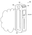
- FIG. 1 is a perspective view of a terminal device according to the first embodiment of the present disclosure.
- the terminal device 100 includes a housing 101, a jog dial 103, a touch panel 105, a display 107, and a speaker 109.
- the casing 101 is a rectangular parallelepiped with a hole in the longitudinal direction through which a user passes a finger. The user can firmly hold the housing 101 by inserting, for example, four fingers into the hole.
- the terminal device 100 is carried, for example, during exercise such as a user's running while being held in this manner.
- the jog dial 103 is provided on the surface (a corner portion in the illustrated example) of the casing 101. For example, when the casing 101 is gripped by the user, the jog dial 103 is rotated or pressed by the user's thumb. Note that the jog dial 103 may be operated by a finger on the opposite side of the user from holding the housing 101.
- the touch panel 105 and the display 107 are arranged so as to face the user when the casing 101 is gripped, and display a GUI for realizing various functions to be described later.
- the speaker 109 outputs sound toward the user as necessary.
- the jog dial 103 is an operation unit operable in a specific direction.
- the jog dial 103 accepts a rotation operation in the circumferential direction of the dial and a pressing operation in the radial direction of the dial.
- Such an operation unit has a lower degree of freedom of operation than, for example, the touch panel 105.
- the operation unit does not depend on the user's vision. There is an advantage that it is easy to operate 101 or the user himself / herself in a vibrating state.
- the touch panel 105 is not combined with the GUI displayed on the display 107, but is simply used as a means for detecting touch, dragging in a specific direction, flicking, etc., as with the jog dial 103.
- the operation unit can be operated in the direction.
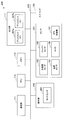
- FIG. 2 is a block diagram schematically illustrating a hardware configuration of the terminal device according to the first embodiment of the present disclosure.
- the terminal device 100 includes a communication unit 111, a CPU (Central Processing Unit) 113, a memory 115, an output unit 117, an operation unit 119, and a sensor 121 as a hardware configuration.
- the terminal device 100 may further include an airbag 133 described later. Each of these components is connected to each other by a bus 135.
- the communication unit 111 is a communication device that performs wireless communication such as a mobile phone network or Wi-Fi.
- the terminal device 100 receives, for example, information for running navigation described later, distributed music content, and the like by communication executed by the communication unit 111.
- the CPU 113 operates according to the program stored in the memory 115 to control each unit of the terminal device 100 to realize various functions.
- the CPU 113 implements a running navigation function and a music playback function. Details of functions realized in the terminal device 100 will be described later.
- the memory 115 temporarily or permanently stores various data used in the terminal device 100.
- the memory 115 stores program code for operating the CPU 113.
- the memory 115 may store various types of information for running navigation, such as course information, user speed, split time, calorie consumption, and the like.
- the memory 115 can store content data for the music playback function.
- the output unit 117 includes a display 107 and a speaker 109.
- the display 107 displays an image according to the control of the CPU 113.
- the speaker 109 outputs sound according to the control of the CPU 113.
- the operation unit 119 includes a touch panel 105 and a jog dial 103.
- the touch panel 105 is disposed on the surface of the display 107 and detects the position of the user's contact with the display 107.
- the jog dial 103 is disposed on the surface of the housing 101 as described above, and is rotated or pressed in a predetermined direction by the user.
- the sensor 121 includes an acceleration sensor 123, a gyro sensor 125, a temperature sensor 127, a microphone 129, and a GPS (Global Positioning System) receiver 131. These sensors are used to detect the position and orientation of the terminal device 100, the surrounding environment, and the like, as will be described later.
- the sensor 121 may include an atmospheric pressure sensor, a humidity sensor, a geomagnetic sensor, an optical sensor, and the like.
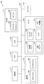
- FIG. 3 is a block diagram schematically illustrating a functional configuration of the terminal device according to the first embodiment of the present disclosure.
- the terminal device 100 includes a control unit 151, a position information acquisition unit 153, an attitude determination unit 155, an environment information acquisition unit 157, as functional configurations realized by software by the CPU 113.
- An output data generation unit 159, an image display unit 161, and an audio output unit 163 are included.
- the control unit 151 controls each unit of the terminal device 100 based on information input from the communication unit 111 and the operation unit 119. For example, the control unit 151 causes the output data generation unit 159 to generate running navigation information based on the information acquired by the position information acquisition unit 153 and the environment information acquisition unit 157. Also, the control unit 151 causes the output data generation unit 159 to generate audio data for music playback using the content data stored in the memory 115. Furthermore, the control unit 151 may cause the output data generation unit 159 to generate data for displaying the GUI for the running navigation function and the music playback function.
- control unit 151 acquires the result of the attitude determination unit 155 determining the attitude of the terminal device 100.
- the control unit 151 selectively realizes either a function related to running navigation or a function related to a music playback function corresponding to the operation acquired by the jog dial 103 according to the attitude of the terminal device 100. A specific example of this selection will be described later.
- control unit 151 may acquire the result of the environment information acquisition unit 157 determining the vibration state of the terminal device 100. In this case, the control unit 151 switches the function realized for the music playback function in accordance with the operation acquired by the jog dial 103 according to the vibration state of the terminal device 100. A specific example of this switching will also be described later.
- the position information acquisition unit 153 performs, for example, predetermined information based on the data acquired from the GPS receiver 131 included in the sensor 121 or the communication unit 111 that performs Wi-Fi communication, to thereby detect the position information of the terminal device 100. To get.
- the position information acquisition unit 153 provides the acquired position information to the control unit 151.
- the attitude determination unit 155 determines the attitude of the terminal device 100 by executing a predetermined calculation based on data acquired from the acceleration sensor 123 and / or the gyro sensor 125 included in the sensor 121, for example. A specific example of the posture of the terminal device 100 determined by the posture determination unit 155 will be described later.
- the posture determination unit 155 provides the control unit 151 with the result of determining the posture.
- the environment information acquisition unit 157 performs, for example, information indicating the surrounding environment of the terminal device 100 by performing a predetermined calculation based on data acquired from the acceleration sensor 123, the temperature sensor 127, and / or the microphone 129 included in the sensor 121. get. For example, the environment information acquisition unit 157 determines the vibration state of the terminal device 100 based on the data acquired from the acceleration sensor 123. Further, the environment information acquisition unit 157 may specify the temperature around the terminal device 100 based on the data acquired from the temperature sensor 127.
- the environmental information acquisition unit 157 specifies the altitude, weather, brightness, and the like of the terminal device 100. Is also possible.
- the environment information acquisition unit 157 provides the acquired information to the control unit 151.
- the output data generation unit 159 generates various data output from the output unit 117 according to the control of the control unit 151. For example, the output data generation unit 159 generates image and audio data for running navigation. In addition, the output data generation unit 159 may generate audio data for playing back music. Further, the output data generation unit 159 may generate image data for displaying a GUI for controlling the navigation function and the music playback function.
- the image display unit 161 displays an image on the display 107 based on the image data generated by the output data generation unit 159.
- the image displayed by the image display unit 161 on the display 107 includes an image for displaying running navigation information and a GUI image for controlling the running navigation function and the music playback function.
- the audio output unit 163 outputs audio from the speaker 109 based on the audio data generated by the output data generation unit 159.
- the sound output from the speaker 109 by the sound output unit 163 includes the sound of running navigation information (for example, route guidance, elapsed distance, pace instruction, etc.) and the sound of the music to be played.
- FIG. 4 is a diagram for describing functions realized when the jog dial is operated in a state where the terminal device is held in a vertical posture in the first embodiment of the present disclosure.
- the terminal device 100 when the user holds the terminal device 100 in a vertical posture, the terminal device 100 is set to the music playback mode.
- the vertical posture means the posture of the terminal device 100 such that the longitudinal direction of the rectangular parallelepiped casing 101 is substantially the vertical direction (y-axis direction shown in the drawing).
- Whether the terminal device 100 is in the vertical posture can be determined based on, for example, the inclination of the casing 101 detected by the gyro sensor 125. Note that the inclination of the housing 101 may be detected by the acceleration sensor 123.
- the music selection screen 1101 or the music playback screen 1103 is displayed on the display 107.
- the music selection screen 1101 one of music icons arranged in one direction is selected, and the user can sequentially change the selected icons by rotating the jog dial 103.
- the icon can be, for example, a display of music in album units. It should be noted that the music icon selection may be directly executed by an operation via the touch panel 105.
- the music playback screen 1103 is displayed on the display 107, and playback of the music corresponding to the selected icon is started.
- the music selection screen 1101 is displayed again, and the user can select another music icon by rotating the jog dial 103. It should be noted that the start of music playback and the display of the music selection screen can also be directly executed by an operation via the touch panel 105, for example, by touching a music icon or flicking the music playback screen.
- the jog dial 103 is operated depending on whether the user is running or stopped.
- the functions realized by can be switched. Whether the user is running or stopped can be determined, for example, by detecting the vibration state of the terminal device 100 from the acceleration change of the casing 101 detected by the acceleration sensor 123.
- the acceleration sensor 123 may detect a change in the acceleration of the housing 101 and determine that the user is running based on the pitch of the periodic change in acceleration. Note that the vibration state of the terminal device 100 may be detected using a vibration sensor provided separately.
- each function described above can be realized as another function when the user is running (during a break).
- a music playback screen 1103 is displayed on the display 107, and the volume of music played back is controlled when the user rotates the jog dial 103.
- the music playback is started / stopped. Further, when the user presses and holds the jog dial 103, the music being played at that time is skipped.
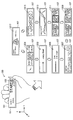
- FIG. 5 is a diagram for describing functions realized when the jog dial is operated in a state where the terminal device is held in the horizontal posture in the first embodiment of the present disclosure.
- the terminal device 100 is set to the navigation mode when the user holds the terminal device 100 in the horizontal posture.
- the horizontal posture means the posture of the terminal device 100 such that the longitudinal direction of the rectangular parallelepiped casing 101 is substantially horizontal (direction in the xz plane shown in the drawing). Whether the terminal device 100 is in the horizontal posture can be determined based on, for example, the inclination of the casing 101 detected by the gyro sensor 125 or the acceleration sensor 123.
- navigation screens 1201 to 1217 are displayed on the display 107.
- the user can switch and display each navigation screen by rotating the jog dial 103.
- the user presses the jog dial 103 if the displayed navigation screen is a screen for selecting something, the selection is executed, and if not, the stopwatch is started / stopped. It should be noted that switching of the navigation screen and selection on the navigation screen can be directly executed by an operation via the touch panel 105, for example, touch or flick.
- the navigation screen in the illustrated example is as follows. Time / current position / route guidance display 1201, route guidance display 1203, target distance and current distance display 1205, split time display 1207, route candidate display 1209, route selection display 1211, speed up / down display 1213, calorie consumption display 1215, And a reward song display 1217.
- These screens are examples, and other screens that provide various information can be displayed as navigation screens.
- the contents of the screen displayed as the navigation screen refer to the running navigation information already provided as described in, for example, JP2012-35071A and JP2012-20134A. Therefore, the detailed description is omitted here.
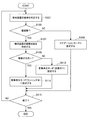
- FIG. 6 is a flowchart illustrating an example of processing according to the first embodiment of the present disclosure.
- the posture determination unit 155 determines the posture of terminal device 100 (step S101).
- the posture determination unit 155 calculates the tilt angle of the housing 101 from the detection value of the gyro sensor 125, for example.
- the posture determination unit 155 determines that the posture of the terminal device 100 is the vertical posture / horizontal posture, for example, when the tilt angle is within a predetermined range.
- a determination having a so-called hysteresis in which the range of the tilt angle for the determination is changed depending on whether the result of the previous determination is the vertical posture or the horizontal posture may be executed. .
- step S101 the determination result in step S101 is provided to the control unit 151, and the control unit 151 branches the process depending on whether or not the terminal device 100 is in the vertical posture (step S103).
- the control unit 151 sets the terminal device 100 to the music playback mode, but in the illustrated example, the determination of vibration is further performed before that (steps S107 to S113). ).
- the control unit 151 sets the terminal device 100 to the navigation mode as shown in FIG. 5 (step S105). .
- the environment information acquisition unit 157 determines the vibration state of the terminal device 100 (step S107).
- the environment information acquisition unit 157 detects the acceleration change of the housing 101 from the detection value of the acceleration sensor 123, for example.
- the environment information acquisition unit 157 determines that the terminal device 100 is in a state of being greatly vibrated, for example, when the acceleration change period is short and the amplitude is large. Even when this determination is repeatedly performed, a determination having a so-called hysteresis, in which the period for determination or the threshold of amplitude is changed according to the result of the previous determination, may be performed as in the determination of the posture. .
- step S109 the determination result in step S107 is provided to the control unit 151, and the control unit 151 branches the process depending on whether the vibration of the terminal device 100 is large (step S109). If the vibration of the terminal device 100 is large (YES), the control unit 151 determines that the user is running and sets the terminal device 100 to the running music playback mode (step S111). On the other hand, when the vibration of the terminal device 100 is not large (NO), the control unit 151 determines that the user is resting, and sets the terminal device 100 to the resting music reproduction mode (step S113). The above process is repeated until a predetermined end condition (the terminal device 100 is turned off, the function is ended by a user operation, etc.) is satisfied (step S115).
- the function realized by rotating or pressing the jog dial of the terminal device is switched according to the attitude of the terminal device.
- various functions can be performed with simple procedures even when the terminal device is carried by the user during exercise such as running by switching the function according to the posture of the terminal device. Can be realized by operating the same operation unit.
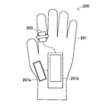
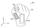
- FIG. 7 is a plan view of a terminal device according to the second embodiment of the present disclosure.
- the terminal device 200 includes a glove 201, a touch sensor 203, and displays 207a and 207b.
- the terminal device 200 has a touch sensor 203 and a display 207 arranged on the surface of a glove 201 worn by a user, and can be said to be a kind of so-called wearable computer.
- the touch sensor 203 is arranged at the base of the index finger of the glove 201, and can be operated with the thumb when the user grasps the hand wearing the glove 201. In addition, the touch sensor 203 may be operated with a finger of a hand opposite to the hand on which the user wears the glove 201 (in the illustrated example, the glove 201 is worn on the left hand, and thus the right hand).
- the touch sensor 203 can be, for example, a pressure type or electrostatic type touch sensor.
- the display 207 a is disposed at the base of the thumb of the glove 201, and the display 207 b is disposed at the back of the glove 201.
- the touch sensor 203 is a capacitance type touch sensor
- the glove 201 is fingerless gloves so that the touch sensor 203 can be operated with a finger of the hand to which the glove 201 is attached.
- conductive fibers may be disposed on the fingertip portion of the glove 201.
- the touch sensor 203, the display 207a, and the display 207b have different housings. These cases are independently arranged on the surface of the glove 201 and connected to each other by a bus line or the like. Circuit components such as a communication unit, a CPU, a memory, and a sensor, which will be described later, are stored in one of the casings, or are stored in a casing that is separately disposed on or inside the glove 201. In the illustrated example, these circuit components are stored in the housing of the display 207b.
- the touch sensor 203 is an operation unit that can be operated in a specific direction.
- the touch sensor 203 has a sliding operation in the in-plane direction of the sensor surface (a direction parallel to the palm and intersecting the index finger), and a touch operation in the vertical direction (a direction perpendicular to the palm) ( It can also be said to be a pressing operation).
- the terminal device 200 can be operated by a simple operation that can be performed using only the thumb of the hand wearing the glove 201, for example.
- FIG. 8 is a block diagram schematically illustrating a hardware configuration of a terminal device according to the second embodiment of the present disclosure.
- the terminal device 200 includes a communication unit 111, a CPU 113, a memory 115, an output unit 117, an operation unit 119, and a sensor 121 as a hardware configuration.
- the terminal device 100 may further include an airbag 133 described later. Each of these components is connected to each other by a bus 135.
- the communication unit 111, the CPU 113, the memory 115, and the sensor 121 are the same as those of the terminal device 100 according to the first embodiment, and thus detailed description thereof is omitted. To do. Also, the functional configuration of the terminal device 200 is the same as the functional configuration of the terminal device 100 according to the first embodiment, and thus detailed description thereof is omitted.
- the output unit 117 includes a display 207a and a display 207b.
- the displays 207a and 207b display images according to the control of the CPU 113, respectively.
- the output unit 117 may further include a speaker.
- the operation unit 119 includes a touch sensor 203.
- the touch sensor 203 is arranged on the surface of the glove 201 as described above, and acquires a slide or touch (pressing) operation in a predetermined direction by the user.
- the operation unit 119 may further include a touch panel provided on the display 207a or the display 207b.
- FIG. 9 is a diagram illustrating a state in which the touch sensor is operated in a state where the terminal device is in the vertical posture in the second embodiment of the present disclosure.
- the vertical posture means a posture of the terminal device 200 such that the surface of the back of the hand of the glove 201 is close to a vertical surface (a surface parallel to the y-axis shown in the drawing).
- Whether the terminal device 200 is in the vertical posture can be determined based on, for example, the inclination of the casing (the casing in which the gyro sensor 125 is stored; for example, the casing of the display 207b) detected by the gyro sensor 125.
- the inclination of the housing may be detected by the acceleration sensor 123.
- the terminal device 200 When the terminal device 200 is in the vertical posture, the terminal device 200 is set to the music playback mode as in the first embodiment.
- a music selection screen or a music playback screen is displayed on the display 207a. These screens are not shown, but may be the same screens as the music selection screen 1101 and the music playback screen 1103 in the first embodiment, for example.
- On the music selection screen one of the music icons arranged in one direction is selected, and the user can sequentially change the selected icons by a slide operation on the touch sensor 203. .
- the music playback screen is displayed on the display 207a, and playback of the music corresponding to the selected icon starts. Is done.
- the music selection screen is displayed again on the display 207a, and when the user performs a slide operation on the touch sensor 203, another music is displayed. An icon can be selected.
- the function realized by the operation of the touch sensor 203 may be switched between when the user is running and when the user is stopped. Whether the user is running or stopped can be determined, for example, by detecting the vibration state of the terminal device 200 from the acceleration change of the casing detected by the acceleration sensor 123. Note that the vibration state of the terminal device 200 can be used as information indicating arm swing while the user is running, for example.
- each function described above can be realized as a function when the user is stopped (during a break).
- a music playback screen is displayed on the display 207a, and when the user performs a slide operation on the touch sensor 203, the volume of the music played is controlled.
- the music playback is started / stopped.
- the music being played at that time is skipped.
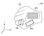
- FIG. 10 is a diagram illustrating a state in which the touch sensor is operated in a state where the terminal device is in the horizontal posture in the second embodiment of the present disclosure.
- the horizontal posture means the posture of the terminal device 200 such that the surface of the back of the hand of the glove 201 is close to the horizontal plane (xz plane shown in the figure). Whether the terminal device 200 is in the horizontal posture can be determined based on, for example, the inclination of the casing detected by the gyro sensor 125 or the acceleration sensor 123.
- the terminal device 200 When the terminal device 200 is in the horizontal posture, the terminal device 200 is set to the navigation mode as in the first embodiment.
- a navigation screen is displayed on the display 207b.
- the navigation screen is not shown, it may be the same screen as the navigation screens 1201 to 1217 in the first embodiment, for example.
- the user can switch and display each navigation screen by executing a slide operation on the touch sensor 203. Further, when the user performs a short touch operation on the touch sensor, if the displayed navigation screen is a screen for selecting something, the selection is performed, and if not, the stopwatch is started / stopped.
- Switching of functions according to the attitude of the terminal device 200 in the present embodiment described above is basically the same as in the first embodiment. However, in the present embodiment, not only functions realized in response to an operation (slide or touch) in a predetermined direction on the touch sensor 203 are switched according to the attitude of the terminal device 200, but various screens are displayed.
- the display to be switched is different from the first embodiment in that the display 207a is switched when the terminal device 200 is in the vertical posture and the display 207b is switched when the terminal device 200 is in the horizontal posture.
- an image can be displayed on a display that is easier for the user to view by switching the display to be used according to the attitude of the terminal device 200. .
- FIG. 11 is a diagram for describing a modification example of the second embodiment of the present disclosure.
- the terminal device 250 according to the modification includes a glove 201, a strain gauge 253, and displays 207a and 207b.
- the terminal device 250 is obtained by providing a strain gauge 253 in place of the touch sensor 203 in the terminal device 200 described above.
- the strain gauge 253 is disposed on the surface of the glove 201 (which may be the palm side or the back side of the hand) from the index finger to the wrist.
- the strain gauge 253 disposed on the palm surface of the glove 201 is compressed when the user grasps the hand wearing the glove 201 and is pulled when the hand is opened.
- the strain gauge 253 disposed on the back surface of the glove 201 is pulled when the user grasps the hand wearing the glove 201 and is compressed when the hand is opened.
- a threshold value may be set for the amount of compression or tension, and a case where the user strongly grasps the hand wearing the glove 201 may be detected separately.
- the strain gauge 253 is also an operation unit operable in a specific direction.
- the strain gauge 253 accepts a deformation operation in the compression-tension direction caused by the user grasping or opening the hand wearing the glove 201.
- the terminal device 250 can be operated with an uncomfortable operation.
- the operations that are selectively realized when the terminal device 250 is in the vertical position and in the horizontal position are the same as those described with reference to FIGS. 9 and 10 above.
- An operation in which the user grasps and opens the hand wearing the glove 201 is a sliding operation on the touch sensor 203 in the above example, and an operation in which the user strongly grasps the hand is an operation on the touch sensor 203 in the above example.
- FIG. 12 is a perspective view of a terminal device according to the third embodiment of the present disclosure.
- the terminal device 300 includes a housing 101, a button 303, a touch panel 105, a display 107, and a speaker 109.
- the terminal device 300 according to the present embodiment is different from the terminal device 100 according to the first embodiment in that it includes a button 303 as an operation unit, but is the same as the terminal device 100 in other points. Therefore, detailed description of components other than the button 303 is omitted here.
- the button 303 is provided on the surface (a corner portion in the illustrated example) of the housing 101, and is pressed with the user's thumb when the terminal device 100 is gripped by the user. Note that the button 303 may be operated with a finger on the opposite side of the hand from which the user is holding the housing 101.
- the button 303 includes a center button 303a and a direction button 303b.
- the center button 303 a is provided at the center of the button 303 and accepts a pressing operation in a direction perpendicular to the button 303.
- the direction button 303b is provided around the center button 303a, and similarly accepts a pressing operation in a direction perpendicular to the button 303. Note that the operation accepted by the direction button 303b is an operation of instructing the button 303 in any of the four directions of up, down, left, or right, so that this operation is up, down, left, or right. May be interpreted as operations in the respective directions.
- the terminal device 300 is set to the music playback mode in the vertical posture and is set to the navigation mode in the horizontal posture.
- the center button 303a has a music playback start / stop function
- the up and down direction buttons 303b have a volume control function
- the left and right direction buttons 303b have skip and fast forward functions.
- Each function is assigned.
- a navigation screen switching function is assigned to the direction button 303b
- a selection or stopwatch start / stop function on the navigation screen is assigned to the center button 303a. Note that these functions can also be realized by an operation via the touch panel 105.
- FIG. 13 is a perspective view of a terminal device according to the fourth embodiment of the present disclosure.
- the terminal device 400 includes a housing 101, a jog dial 103, a touch panel 105, a display 107, a speaker 109, and an airbag 133.
- the terminal device 400 according to the present embodiment is different from the terminal device 100 according to the first embodiment in that it includes an airbag 133, but is the same as the terminal device 100 in other points.
- portions other than the airbag 133 of the terminal device 400 may be configured similarly to the terminal device 200 according to the second embodiment or the terminal device 300 according to the third embodiment. Therefore, detailed description of components other than the airbag 133 is omitted here.
- the airbag 133 is provided, for example, on the side opposite to the display 107 of the housing 101 as shown in the figure, and mitigates the impact on the user or the terminal device 100 when the user operates when the user falls.
- the airbag 133 is controlled by, for example, the control unit 151 realized by the CPU 113 (see FIGS. 2 and 8). In this case, the control unit 151 operates the airbag 133 when the environment information acquisition unit 157 detects an acceleration exceeding the threshold value.
- control unit 151 may activate the airbag 133 and display a message transmission screen on the display 107 to enable an operation of transmitting a message to the emergency contact.
- control unit 151 may activate the airbag 133 and automatically transmit a message to the emergency contact address.
- the message sent to the emergency contact may automatically include the user's location and time.
- the airbag 133 may be installed at a plurality of locations of the housing 101.
- the control unit 151 may specify the direction in which the user has fallen based on the detection result of the acceleration by the environment information acquisition unit 157, and activate the airbag 133 corresponding to the direction. Moreover, it replaces with the airbag 133, or the nozzle which injects an air jet may be provided with this.
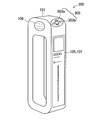
- FIG. 14 is a perspective view of a terminal device according to the fifth embodiment of the present disclosure.
- the terminal device 500 includes a housing 101, a jog dial 103, a touch panel 105, a display 107, a speaker 109, and a detachable groove 511.
- the terminal device 500 which concerns on this embodiment differs from the terminal device 100 which concerns on 1st Embodiment by the point which has the attachment / detachment groove
- the portions other than the attachment / detachment groove 511 of the terminal device 500 may be configured in the same manner as any of the terminal devices 200 to 400 according to the second to fourth embodiments. Therefore, detailed description of components other than the attaching / detaching groove 511 is omitted here.
- the attachment / detachment groove 511 is engraved on the surface of the housing 101 and engages with an attachment / detachment portion of another terminal device 513. Accordingly, another terminal device 513 can be attached to the terminal device 500.
- the size of the other terminal device 513 is not particularly limited, but may be a size that covers the entire display 107 as in the illustrated example, for example. In another example, the other terminal device 513 may cover only a part of the display 107 or may be attached to the terminal device 100 without covering the display 107.
- an electrical contact can be provided in the attachment / detachment groove 511.
- the terminal device 500 and the other terminal device 513 are not only structurally connected but also electrically connected by engaging the attaching / detaching portion of the other terminal device 513 with the attaching / detaching groove 511.
- a part of the function of the terminal device 500 can be realized in the other terminal device 513.
- the terminal device 500 can detect position information, inclination of the housing 101, and the like using detection results of these sensors. .
- the terminal device 500 may request a processor of another terminal device 513 for a part or all of the arithmetic processing by the CPU 113. Further, the terminal device 500 may use a display or a speaker of another terminal device 513 instead of providing information to the user via the display 107 or the speaker 109.
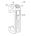
- FIG. 15 is a perspective view of a terminal device according to the sixth embodiment of the present disclosure.
- the terminal device 600 includes a housing 601, a jog dial 103, a touch panel 105, a display 107, and a belt 611.
- the terminal device 600 according to the present embodiment is different from the terminal device 100 according to the first embodiment in the shape of the housing 601 and the point having the belt 611, but is the same as the terminal device 100 in other points. is there.
- portions other than the casing 601 and the belt 611 of the terminal device 600 may be configured similarly to any of the terminal devices 300 to 500 according to the third to fifth embodiments. Therefore, detailed description of components other than the housing 601 and the belt 611 is omitted here.
- the housing 601 has a rectangular plate shape, and a belt 611 is connected to both ends in the longitudinal direction.
- the belt 611 includes a connection portion 611a, a rigid portion 611b, and an expansion / contraction portion 611c.
- a plurality of the rigid portions 611b are arranged on the opposite side of the housing 601 with the connection portion 611a interposed therebetween, and the plurality of rigid portions 611b are connected by the expansion / contraction portions 611c.
- FIG. 15A when the stretchable portion 611c contracts and the adjacent rigid portions 611b are in close contact with each other, a grip handle is formed by the close rigid portions 611b. As with the terminal device 100 according to the embodiment, it is easy for the user to hold and use it.
- FIG. 15B when the stretchable portion 611c is extended and the adjacent rigid portions 611b are separated from each other, the entire belt 611 becomes a stretchable belt portion. It is easy to wrap around the user's arm or wrist.
- FIG. 16 is a perspective view of a terminal device according to the seventh embodiment of the present disclosure.
- the terminal device 700 includes a housing 701, a jog dial 103, a touch panel 105, a display 107, and a speaker 109.
- the terminal device 700 according to the present embodiment is different from the terminal device 100 according to the first embodiment with respect to the shape of the housing 701, but is otherwise the same as the terminal device 100.
- Portions other than the body 701 may be configured similarly to any of the terminal devices 300 to 500 according to the third to fifth embodiments. Therefore, detailed description of components other than the housing 701 is omitted here.
- the housing 701 is the housing 101 of the terminal device 100 according to the first embodiment, and has a shape in which a portion on the opposite side to the display 107 side is cut across a hole in the longitudinal direction. For example, when the user grips a part on the display 107 side as in the examples shown in FIGS. 4 and 5, the part on the opposite side may not be necessary.
- the casing 701 realizes weight reduction of the terminal device 700 by omitting a casing portion that is not necessary when the user holds the display 107 side.
- FIG. 17 is a flowchart illustrating a process in a modification common to the embodiments of the present disclosure.
- the terminal device 100 according to the first embodiment will be described as an example. However, this processing can also be applied to the terminal devices 200 to 700 according to the second to seventh embodiments.
- the environment information acquisition unit 157 determines the vibration state of the terminal device 100 (step S201).
- the environment information acquisition unit 157 detects the acceleration change of the housing 101 from the detection value of the acceleration sensor 123, for example.
- the environment information acquisition unit 157 determines that the terminal device 100 is in a state of being greatly vibrated, for example, when the acceleration change period is short and the amplitude is large.
- step S203 the determination result in step S201 is provided to the control unit 151, and the control unit 151 branches the process depending on whether the vibration of the terminal device 100 is large (step S203).
- the control unit 151 determines that the user is running, and basically sets the terminal device 100 to the power-saving music playback mode.
- the power-saving music playback mode is a music playback mode that saves power by pausing the touch detection by the touch panel 105 and displaying the GUI on the display 107. In this mode, the operation of the terminal device 100 is performed exclusively using the jog dial 103.
- the control unit 151 determines whether or not the jog dial 103 is pressed and held by the user before setting the power-saving music playback mode (step S205). If the jog dial 103 has not been pressed for a long time (NO), the control unit 151 sets the terminal device 100 to a power-saving music playback mode (step S207). On the other hand, when the jog dial 103 has been pressed for a long time (YES), the control unit 151 recognizes this as a kind of unlocking operation, and the process when the vibration of the terminal device 100 is not large in step S203 (step S209). Transition.
- the control unit 151 determines that the user is resting, and the posture determination unit 155 determines the posture of the terminal device 100 (Ste S209).
- the posture determination unit 155 calculates the tilt angle of the housing 101 from the detection value of the gyro sensor 125, for example.
- the posture determination unit 155 determines that the posture of the terminal device 100 is the vertical posture / horizontal posture, for example, when the tilt angle is within a predetermined range. Note that the determination having the hysteresis as described in the first embodiment may also be performed in the determination of the vibration state and posture of the terminal device 100 in this modification.
- step S209 the determination result in step S209 is provided to the control unit 151, and the control unit 151 branches the process depending on whether or not the terminal device 100 is in the horizontal posture (step S211).
- the control unit 151 sets the terminal device 100 to the navigation mode (step S213).
- the control unit 151 sets the terminal device 100 to the music playback mode.
- the music playback mode set here is a normal music playback mode in which touch detection by the touch panel 105 and GUI display on the display 107 are performed. The above process is repeated until a predetermined end condition (the terminal device 100 is turned off, the function is ended by a user operation, etc.) is satisfied (step S217).
- the posture determination of the terminal device 100 is not performed while the user is running. For example, music playback is stopped when the user unintentionally places the terminal device 100 in the horizontal posture during running. Thus, a malfunction such as starting navigation is prevented. Further, by recognizing the long press of the jog dial 103 as an unlocking operation, the terminal device 100 is switched to the navigation mode when the user puts the terminal device 100 in the horizontal posture with the intention of switching the mode during running. Is possible.
- an IC (Integrated Circuit) card may be mounted on the terminal device to enable electronic money settlement or personal authentication.
- Embodiments of the present disclosure include, for example, an information processing device (terminal device) as described above, a system including an information device, an information processing device or an information processing method executed by the system, It may include a program and a non-transitory tangible medium on which the program is recorded.
- an operation unit operable in a specific direction A posture determination unit that determines the posture of the terminal device having the operation unit; And a control unit that switches a function realized in response to the operation of the operation unit according to the posture.
- the terminal device according to (1) further including a vibration determination unit that determines a vibration state of the terminal device.
- the control unit further switches the function according to the vibration state.
- the control unit determines whether to switch the function according to the posture based on the vibration state.
- the terminal device according to any one of (1) to (8), wherein the operation unit includes a touch sensor that detects sliding or pressing. (10) The terminal device according to any one of (1) to (9), wherein the operation unit includes a strain gauge that detects compression or tension. (11) The terminal device according to any one of (1) to (10), wherein the operation unit includes a button. (12) It further includes a housing that can be carried or worn by a running user, The control unit switches between realizing a function related to music reproduction or a function related to running navigation in accordance with the operation, according to the operation, (1) to (11) The terminal device according to any one of the above.
- the terminal device further comprising a housing and a belt that forms a ring with the housing;
- the belt is Including a plurality of rigid portions, and a stretchable portion disposed between the rigid portions, By contracting the stretchable part, the plurality of rigid parts are in close contact with each other to form a grip handle,
- the terminal device according to any one of (1) to (12), wherein the plurality of rigid portions are separated from each other to form a stretchable belt portion by extending the stretchable portion.
- the device according to any one of (1) to (13), further including a housing and a connecting portion that is provided on a surface of the housing and is at least structurally connected to another terminal device. Terminal equipment.
- the terminal device according to (14), wherein the connection unit is also electrically connected to the other terminal device.
- the terminal device It further includes an acceleration detection unit that detects the acceleration of the casing of the terminal device, and an airbag that reduces the impact on the user of the terminal device or the terminal device, The terminal device according to any one of (1) to (15), wherein the control unit operates the airbag based on the acceleration.
- the control unit operates the airbag based on the acceleration.
- a method for controlling a terminal device comprising: switching a function to be realized in response to the operation according to the posture.
Abstract
Description
1.第1の実施形態
1-1.端末装置の外観
1-2.端末装置のハードウェア構成
1-3.端末装置の機能構成
1-4.選択的に実現される機能の例
1-5.処理フロー
2.第2の実施形態
2-1.端末装置の構成
2-2.選択的に実現される機能の例
2-3.変形例
3.第3の実施形態
4.第4の実施形態
5.第5の実施形態
6.第6の実施形態
7.第7の実施形態
8.変形例
9.補足
(1-1.端末装置の外観)
図1は、本開示の第1の実施形態に係る端末装置の斜視図である。図1を参照すると、端末装置100は、筐体101と、ジョグダイヤル103と、タッチパネル105と、ディスプレイ107と、スピーカー109とを有する。筐体101は角の円い直方体であり、中央部にユーザが指を通すための長手方向の穴を有する。ユーザは、例えば4本の指をこの穴に差し込むことによって、筐体101を固く握ることができる。端末装置100は、例えば、このように握られた状態で、ユーザのランニングなどの運動中に携帯される。
図2は、本開示の第1の実施形態に係る端末装置のハードウェア構成を概略的に示すブロック図である。図2を参照すると、端末装置100は、ハードウェア構成として、通信部111と、CPU(Central Processing Unit)113と、メモリ115と、出力部117と、操作部119と、センサ121とを有する。端末装置100は、さらに後述するエアバッグ133を有してもよい。これらの各構成要素は、バス135によって互いに接続される。
図3は、本開示の第1の実施形態に係る端末装置の機能構成を概略的に示すブロック図である。図3を参照すると、端末装置100は、上記のCPU113によってソフトウェア的に実現される機能構成として、制御部151と、位置情報取得部153と、姿勢判定部155と、環境情報取得部157と、出力データ生成部159と、画像表示部161と、音声出力部163とを有する。
図4は、本開示の第1の実施形態において、端末装置を縦姿勢で把持した状態でジョグダイヤルを操作した場合に実現される機能について説明するための図である。図4を参照すると、ユーザが端末装置100を縦姿勢で把持した状態では、端末装置100が音楽再生モードに設定される。なお、本実施形態において、縦姿勢は、直方体状の筐体101の長手方向がほぼ鉛直方向(図中に示すy軸方向)になるような端末装置100の姿勢を意味する。端末装置100が縦姿勢であることは、例えばジャイロセンサ125が検出した筐体101の傾きに基づいて判定できる。なお、筐体101の傾きは加速度センサ123によって検出されてもよい。
図6は、本開示の第1の実施形態における処理の例を示すフローチャートである。図6を参照すると、まず、姿勢判定部155が端末装置100の姿勢を判定する(ステップS101)。ここで、姿勢判定部155は、例えばジャイロセンサ125の検出値から筐体101の傾き角度を算出する。姿勢判定部155は、例えば傾き角度が所定の範囲にある場合に、端末装置100の姿勢が縦姿勢/横姿勢であると判定する。なお、この判定が繰り返し実行される場合、前回の判定の結果が縦姿勢であったか横姿勢であったかによって判定のための傾き角度の範囲が変更される、いわゆるヒステリシスを有する判定が実行されてもよい。
(2-1.端末装置の構成)
図7は、本開示の第2の実施形態に係る端末装置の平面図である。図7を参照すると、端末装置200は、手袋201と、タッチセンサ203と、ディスプレイ207a,207bとを有する。端末装置200は、ユーザが手に着用する手袋201の表面にタッチセンサ203およびディスプレイ207を配置したものであり、いわゆるウェアラブルコンピュータの一種ともいえる。
図9は、本開示の第2の実施形態において、端末装置を縦姿勢にした状態でタッチセンサを操作した状態を示す図である。本実施形態において、縦姿勢は、手袋201の手の甲部分の面が鉛直面(図中に示すy軸に平行な面)に近くなるような端末装置200の姿勢を意味する。端末装置200が縦姿勢であることは、例えばジャイロセンサ125が検出した筐体(ジャイロセンサ125が格納される筐体。例えばディスプレイ207bの筐体でありうる)の傾きに基づいて判定できる。なお、筐体の傾きは加速度センサ123によって検出されてもよい。
図11は、本開示の第2の実施形態の変形例について説明するための図である。図11を参照すると、変形例に係る端末装置250は、手袋201と、ひずみゲージ253と、ディスプレイ207a,207bとを有する。端末装置250は、上記の端末装置200において、タッチセンサ203に代えてひずみゲージ253を設けたものである。
図12は、本開示の第3の実施形態に係る端末装置の斜視図である。図12を参照すると、端末装置300は、筐体101と、ボタン303と、タッチパネル105と、ディスプレイ107と、スピーカー109とを有する。本実施形態に係る端末装置300は、操作部としてボタン303を有する点で第1の実施形態に係る端末装置100とは異なるが、それ以外の点では端末装置100と同様である。従って、ここでは、ボタン303以外の構成要素については詳細な説明を省略する。
図13は、本開示の第4の実施形態に係る端末装置の斜視図である。図13を参照すると、端末装置400は、筐体101と、ジョグダイヤル103と、タッチパネル105と、ディスプレイ107と、スピーカー109と、エアバッグ133とを有する。本実施形態に係る端末装置400は、エアバッグ133を有する点で第1の実施形態に係る端末装置100とは異なるが、それ以外の点では端末装置100と同様である。なお、端末装置400のエアバッグ133以外の部分は、第2の実施形態に係る端末装置200または第3の実施形態に係る端末装置300と同様に構成されていてもよい。従って、ここでは、エアバッグ133以外の構成要素については詳細な説明を省略する。
図14は、本開示の第5の実施形態に係る端末装置の斜視図である。図14を参照すると、端末装置500は、筐体101と、ジョグダイヤル103と、タッチパネル105と、ディスプレイ107と、スピーカー109と、着脱溝511とを有する。本実施形態に係る端末装置500は、着脱溝511を有する点で第1の実施形態に係る端末装置100とは異なるが、それ以外の点では端末装置100と同様である。なお、端末装置500の着脱溝511以外の部分は、第2~第4の実施形態に係る端末装置200~400のいずれかと同様に構成されていてもよい。従って、ここでは、着脱溝511以外の構成要素については詳細な説明を省略する。
図15は、本開示の第6の実施形態に係る端末装置の斜視図である。図15を参照すると、端末装置600は、筐体601と、ジョグダイヤル103と、タッチパネル105と、ディスプレイ107と、ベルト611とを有する。本実施形態に係る端末装置600は、筐体601の形状と、ベルト611を有する点とで第1の実施形態に係る端末装置100とは異なるが、それ以外の点では端末装置100と同様である。なお、端末装置600の筐体601およびベルト611以外の部分は、第3~第5の実施形態に係る端末装置300~500のいずれかと同様に構成されていてもよい。従って、ここでは、筐体601およびベルト611以外の構成要素については詳細な説明を省略する。
図16は、本開示の第7の実施形態に係る端末装置の斜視図である。図16を参照すると、端末装置700は、筐体701と、ジョグダイヤル103と、タッチパネル105と、ディスプレイ107と、スピーカー109とを有する。本実施形態に係る端末装置700は、筐体701の形状について第1の実施形態に係る端末装置100とは異なるが、それ以外の点では端末装置100と同様である、なお端末装置700の筐体701以外の部分は、第3~第5の実施形態に係る端末装置300~500のいずれかと同様に構成されていてもよい。従って、ここでは、筐体701以外の構成要素については詳細な説明を省略する。
つぎに、図17を参照して、本開示の各実施形態に共通の変形例について説明する。
本開示の実施形態は、例えば、上記で説明したような情報処理装置(端末装置)、情報装置を含むシステム、情報処理装置またはシステムで実行される情報処理方法、情報処理装置を機能させるためのプログラム、およびプログラムが記録された一時的でない有形の媒体を含みうる。
(1)特定の方向に操作可能な操作部と、
前記操作部を有する端末装置の姿勢を判定する姿勢判定部と、
前記姿勢に応じて、前記操作部の操作に対応して実現される機能を切り替える制御部と
を備える端末装置。
(2)前記端末装置の振動状態を判定する振動判定部をさらに備える、前記(1)に記載の端末装置。
(3)前記制御部は、前記振動状態に応じて前記機能をさらに切り替える、前記(2)に記載の端末装置。
(4)前記制御部は、前記振動状態に基づいて、前記姿勢に応じて前記機能を切り替えるか否かを決定する、前記(2)に記載の端末装置。
(5)前記制御部は、前記操作部が所定のパターンの操作を検出した場合、前記振動状態にかかわらず、前記姿勢に応じて前記機能を切り替える、前記(4)に記載の端末装置。
(6)前記振動判定部は、前記端末装置の筐体の加速度変化に基づいて前記振動状態を判定する、前記(2)~(5)のいずれか1項に記載の端末装置。
(7)前記姿勢判定部は、前記端末装置の筐体の傾き角度に基づいて前記姿勢を判定する、前記(1)~(6)のいずれか1項に記載の端末装置。
(8)前記操作部は、回転または押下を検出するジョグダイヤルを含む、前記(1)~(7)のいずれか1項に記載の端末装置。
(9)前記操作部は、スライドまたは押下を検出するタッチセンサを含む、前記(1)~(8)のいずれか1項に記載の端末装置。
(10)前記操作部は、圧縮または引張を検出するひずみゲージを含む、前記(1)~(9)のいずれか1項に記載の端末装置。
(11)前記操作部は、ボタンを含む、前記(1)~(10)のいずれか1項に記載の端末装置。
(12)ランニング中のユーザが携帯または装着することが可能な筐体をさらに備え、
前記制御部は、前記姿勢に応じて、前記操作に対応して音楽再生に関連する機能を実現するか、ランニングのナビゲーションに関連する機能を実現するかを切り替える、前記(1)~(11)のいずれか1項に記載の端末装置。
(13)筐体と、前記筐体とともに輪を形成するベルトとをさらに備え、
前記ベルトは、
複数の剛性部と、前記各剛性部の間に配置される伸縮部とを含み、
前記伸縮部が収縮することによって前記複数の剛性部が互いに密着してグリップハンドルを形成し、
前記伸縮部が伸長することによって前記複数の剛性部が互いに分離して伸縮性のベルト部分を形成する、前記(1)~(12)のいずれか1項に記載の端末装置。
(14)筐体と、前記筐体の表面に設けられ、他の端末装置と少なくとも構造的に連結される連結部とをさらに備える、前記(1)~(13)のいずれか1項に記載の端末装置。
(15)前記連結部は、前記他の端末装置と電気的にも連結される、前記(14)に記載の端末装置。
(16)前記端末装置の筐体の加速度を検出する加速度検出部と、前記端末装置のユーザまたは前記端末装置への衝撃を緩和するエアバッグをさらに備え、
前記制御部は、前記加速度に基づいて前記エアバッグを作動させる、前記(1)~(15)のいずれか1項に記載の端末装置。
(17)複数のディスプレイをさらに備え、
前記制御部は、前記姿勢に応じて、前記ディスプレイのうち画像を表示するディスプレイを切り替える、前記(1)~(16)のいずれか1項に記載の端末装置。
(18)特定の方向に操作可能な操作部の操作を検出することと、
前記操作部を有する端末装置の姿勢を判定することと、
前記姿勢に応じて、前記操作に対応して実現させる機能を切り替えることと
を含む端末装置の制御方法。
(19)特定の方向に操作可能な操作部の操作を検出する機能と、
前記操作部を有する端末装置の姿勢を判定する機能と、
前記姿勢に応じて、前記操作に対応して実現させる機能を切り替える機能と
をコンピュータに実現させるためのプログラム。
101,601,701 筐体
103 ジョグダイヤル
107,207 ディスプレイ
111 通信部
113 CPU
115 メモリ
117 出力部
119 操作部
121 センサ
133 エアバッグ
151 制御部
153 位置情報取得部
155 姿勢判定部
157 環境情報取得部
201 手袋
203 タッチセンサ
253 ひずみゲージ
303 ボタン
511 着脱溝
611 ベルト
Claims (19)
- 特定の方向に操作可能な操作部と、
前記操作部を有する端末装置の姿勢を判定する姿勢判定部と、
前記姿勢に応じて、前記操作部の操作に対応して実現される機能を切り替える制御部と
を備える端末装置。 - 前記端末装置の振動状態を判定する振動判定部をさらに備える、請求項1に記載の端末装置。
- 前記制御部は、前記振動状態に応じて前記機能をさらに切り替える、請求項2に記載の端末装置。
- 前記制御部は、前記振動状態に基づいて、前記姿勢に応じて前記機能を切り替えるか否かを決定する、請求項2に記載の端末装置。
- 前記制御部は、前記操作部が所定のパターンの操作を検出した場合、前記振動状態にかかわらず、前記姿勢に応じて前記機能を切り替える、請求項4に記載の端末装置。
- 前記振動判定部は、前記端末装置の筐体の加速度変化に基づいて前記振動状態を判定する、請求項2に記載の端末装置。
- 前記姿勢判定部は、前記端末装置の筐体の傾き角度に基づいて前記姿勢を判定する、請求項1に記載の端末装置。
- 前記操作部は、回転または押下を検出するジョグダイヤルを含む、請求項1に記載の端末装置。
- 前記操作部は、スライドまたは押下を検出するタッチセンサを含む、請求項1に記載の端末装置。
- 前記操作部は、圧縮または引張を検出するひずみゲージを含む、請求項1に記載の端末装置。
- 前記操作部は、ボタンを含む、請求項1に記載の端末装置。
- ランニング中のユーザが携帯または装着することが可能な筐体をさらに備え、
前記制御部は、前記姿勢に応じて、前記操作に対応して音楽再生に関連する機能を実現するか、ランニングのナビゲーションに関連する機能を実現するかを切り替える、請求項1に記載の端末装置。 - 筐体と、前記筐体とともに輪を形成するベルトとをさらに備え、
前記ベルトは、
複数の剛性部と、前記各剛性部の間に配置される伸縮部とを含み、
前記伸縮部が収縮することによって前記複数の剛性部が互いに密着してグリップハンドルを形成し、
前記伸縮部が伸長することによって前記複数の剛性部が互いに分離して伸縮性のベルト部分を形成する、請求項1に記載の端末装置。 - 筐体と、前記筐体の表面に設けられ、他の端末装置と少なくとも構造的に連結される連結部とをさらに備える、請求項1に記載の端末装置。
- 前記連結部は、前記他の端末装置と電気的にも連結される、請求項14に記載の端末装置。
- 前記端末装置の筐体の加速度を検出する加速度検出部と、前記端末装置のユーザまたは前記端末装置への衝撃を緩和するエアバッグをさらに備え、
前記制御部は、前記加速度に基づいて前記エアバッグを作動させる、請求項1に記載の端末装置。 - 複数のディスプレイをさらに備え、
前記制御部は、前記姿勢に応じて、前記ディスプレイのうち画像を表示するディスプレイを切り替える、請求項1に記載の端末装置。 - 特定の方向に操作可能な操作部の操作を検出することと、
前記操作部を有する端末装置の姿勢を判定することと、
前記姿勢に応じて、前記操作に対応して実現させる機能を切り替えることと
を含む端末装置の制御方法。 - 特定の方向に操作可能な操作部の操作を検出する機能と、
前記操作部を有する端末装置の姿勢を判定する機能と、
前記姿勢に応じて、前記操作に対応して実現させる機能を切り替える機能と
をコンピュータに実現させるためのプログラム。
Priority Applications (5)
| Application Number | Priority Date | Filing Date | Title |
|---|---|---|---|
| CN201480012011.XA CN105009040B (zh) | 2013-03-11 | 2014-03-04 | 终端装置、用于终端装置的控制方法和程序 |
| EP14765724.1A EP2975497B1 (en) | 2013-03-11 | 2014-03-04 | Terminal device, terminal device control method, and program |
| JP2015505412A JP6337882B2 (ja) | 2013-03-11 | 2014-03-04 | 端末装置、端末装置の制御方法およびプログラム |
| CN201810581909.9A CN108469878B (zh) | 2013-03-11 | 2014-03-04 | 终端装置及其控制方法和计算机可读存储介质 |
| US14/769,133 US20150378447A1 (en) | 2013-03-11 | 2014-03-04 | Terminal device, control method for terminal device, and program |
Applications Claiming Priority (2)
| Application Number | Priority Date | Filing Date | Title |
|---|---|---|---|
| JP2013047892 | 2013-03-11 | ||
| JP2013-047892 | 2013-03-11 |
Publications (1)
| Publication Number | Publication Date |
|---|---|
| WO2014141951A1 true WO2014141951A1 (ja) | 2014-09-18 |
Family
ID=51536617
Family Applications (1)
| Application Number | Title | Priority Date | Filing Date |
|---|---|---|---|
| PCT/JP2014/055457 WO2014141951A1 (ja) | 2013-03-11 | 2014-03-04 | 端末装置、端末装置の制御方法およびプログラム |
Country Status (5)
| Country | Link |
|---|---|
| US (1) | US20150378447A1 (ja) |
| EP (1) | EP2975497B1 (ja) |
| JP (4) | JP6337882B2 (ja) |
| CN (2) | CN108469878B (ja) |
| WO (1) | WO2014141951A1 (ja) |
Cited By (1)
| Publication number | Priority date | Publication date | Assignee | Title |
|---|---|---|---|---|
| CN105391864A (zh) * | 2015-11-26 | 2016-03-09 | 努比亚技术有限公司 | 基于压力控制移动终端振动的装置和方法 |
Families Citing this family (23)
| Publication number | Priority date | Publication date | Assignee | Title |
|---|---|---|---|---|
| US10275117B2 (en) | 2012-12-29 | 2019-04-30 | Apple Inc. | User interface object manipulations in a user interface |
| US10691230B2 (en) | 2012-12-29 | 2020-06-23 | Apple Inc. | Crown input for a wearable electronic device |
| KR20180128091A (ko) | 2013-09-03 | 2018-11-30 | 애플 인크. | 자기 특성을 갖는 사용자 인터페이스 객체를 조작하는 사용자 인터페이스 |
| US10001817B2 (en) * | 2013-09-03 | 2018-06-19 | Apple Inc. | User interface for manipulating user interface objects with magnetic properties |
| US10545657B2 (en) | 2013-09-03 | 2020-01-28 | Apple Inc. | User interface for manipulating user interface objects |
| US11068128B2 (en) | 2013-09-03 | 2021-07-20 | Apple Inc. | User interface object manipulations in a user interface |
| US10503388B2 (en) | 2013-09-03 | 2019-12-10 | Apple Inc. | Crown input for a wearable electronic device |
| WO2015200889A1 (en) | 2014-06-27 | 2015-12-30 | Apple Inc. | Electronic device with rotatable input mechanism for navigating calendar application |
| US20160004408A1 (en) * | 2014-07-01 | 2016-01-07 | Naver Corporation | Methods, systems and recording mediums for improving mobile devices using user gestures |
| US9841292B2 (en) * | 2014-08-12 | 2017-12-12 | Google Inc. | Screen transitions in a geographic application |
| WO2016036509A1 (en) | 2014-09-02 | 2016-03-10 | Apple Inc. | Electronic mail user interface |
| US20160062571A1 (en) | 2014-09-02 | 2016-03-03 | Apple Inc. | Reduced size user interface |
| TWI582641B (zh) | 2014-09-02 | 2017-05-11 | 蘋果公司 | 按鈕功能性 |
| CN113824998A (zh) | 2014-09-02 | 2021-12-21 | 苹果公司 | 音乐用户界面 |
| US10365807B2 (en) | 2015-03-02 | 2019-07-30 | Apple Inc. | Control of system zoom magnification using a rotatable input mechanism |
| CN106325471B (zh) * | 2015-06-19 | 2020-03-24 | 联想(北京)有限公司 | 一种装置及控制方法 |
| WO2017122648A1 (ja) * | 2016-01-14 | 2017-07-20 | パナソニックIpマネジメント株式会社 | 入力装置 |
| DK201670580A1 (en) | 2016-06-12 | 2018-01-02 | Apple Inc | Wrist-based tactile time feedback for non-sighted users |
| DK179896B1 (en) | 2018-09-11 | 2019-08-30 | Apple Inc. | CONTENT-BASED TACTILE OUTPUTS |
| US11435830B2 (en) | 2018-09-11 | 2022-09-06 | Apple Inc. | Content-based tactile outputs |
| US10739852B2 (en) * | 2019-01-01 | 2020-08-11 | Logan Amstutz | Systems, devices, and/or methods for wristbands |
| US10996761B2 (en) | 2019-06-01 | 2021-05-04 | Apple Inc. | User interfaces for non-visual output of time |
| CN112434594A (zh) * | 2020-11-19 | 2021-03-02 | 维沃移动通信有限公司 | 手套佩戴检测方法、装置、手套及可读存储介质 |
Citations (8)
| Publication number | Priority date | Publication date | Assignee | Title |
|---|---|---|---|---|
| JPH09134249A (ja) * | 1995-11-09 | 1997-05-20 | Toshiba Corp | 携帯型情報機器 |
| JP2006041592A (ja) * | 2004-07-22 | 2006-02-09 | Fujitsu Ltd | 入力装置 |
| JP2008140064A (ja) * | 2006-11-30 | 2008-06-19 | Toshiba Corp | 情報処理装置 |
| JP2011188469A (ja) * | 2010-02-15 | 2011-09-22 | Canon Inc | 情報処理装置、制御方法及びプログラム並びに記録媒体 |
| JP2012020134A (ja) | 2010-07-14 | 2012-02-02 | Adidas Ag | 場所認識フィットネスモニタリング方法、システム及びプログラム製品並びにその応用 |
| JP2012035071A (ja) | 2010-07-14 | 2012-02-23 | Adidas Ag | フィットネスモニタリング方法、システム及びプログラム製品並びにその応用 |
| JP2012155487A (ja) * | 2011-01-25 | 2012-08-16 | Canon Inc | 情報処理装置及びその制御方法、プログラム、並びに記憶媒体 |
| JP2012256153A (ja) | 2011-06-08 | 2012-12-27 | Panasonic Corp | 文字入力装置および携帯端末 |
Family Cites Families (39)
| Publication number | Priority date | Publication date | Assignee | Title |
|---|---|---|---|---|
| JP2000148351A (ja) * | 1998-09-09 | 2000-05-26 | Matsushita Electric Ind Co Ltd | ユ―ザ動作の種類に応じて操作指示をする操作指示出力装置及びコンピュ―タ読み取り可能な記録媒体 |
| JP2002062964A (ja) * | 2000-06-06 | 2002-02-28 | Kenichi Horie | パソコン配列で入力できるテンキーボード型文字入力装置 |
| US6662986B2 (en) * | 2001-10-05 | 2003-12-16 | Nokia Corporation | Mobile phone strap holder apparatus and method |
| US7894177B2 (en) * | 2005-12-29 | 2011-02-22 | Apple Inc. | Light activated hold switch |
| JP4559140B2 (ja) * | 2004-07-05 | 2010-10-06 | ソフトバンクモバイル株式会社 | 電子機器 |
| JP2006033724A (ja) * | 2004-07-21 | 2006-02-02 | Fuji Photo Film Co Ltd | 情報処理装置及び情報処理方法 |
| US20070004451A1 (en) * | 2005-06-30 | 2007-01-04 | C Anderson Eric | Controlling functions of a handheld multifunction device |
| JP4926424B2 (ja) * | 2005-08-01 | 2012-05-09 | 旭化成エレクトロニクス株式会社 | 携帯機器及びその描画処理制御方法 |
| JP2007228136A (ja) * | 2006-02-22 | 2007-09-06 | Funai Electric Co Ltd | リモートコントローラ、映像機器 |
| JP2007286812A (ja) * | 2006-04-14 | 2007-11-01 | Sony Corp | 携帯型電子機器、ユーザインターフェイス制御方法、プログラム |
| JP4485492B2 (ja) * | 2006-06-27 | 2010-06-23 | ソフトバンクモバイル株式会社 | 実行機能選択方法及び移動通信端末装置 |
| US20080005679A1 (en) * | 2006-06-28 | 2008-01-03 | Microsoft Corporation | Context specific user interface |
| CN101155363A (zh) * | 2006-09-30 | 2008-04-02 | 海尔集团公司 | 利用动作感应实现手机控制的方法和装置 |
| JP4662493B2 (ja) * | 2007-09-26 | 2011-03-30 | シャープ株式会社 | リモコン装置 |
| US8942764B2 (en) * | 2007-10-01 | 2015-01-27 | Apple Inc. | Personal media device controlled via user initiated movements utilizing movement based interfaces |
| JP2009141676A (ja) * | 2007-12-06 | 2009-06-25 | Olympus Imaging Corp | 再生装置、デジタルカメラ、スライドショー再生方法、及びプログラム |
| US8423076B2 (en) * | 2008-02-01 | 2013-04-16 | Lg Electronics Inc. | User interface for a mobile device |
| JP2009222921A (ja) * | 2008-03-14 | 2009-10-01 | Fujifilm Corp | 画像表示装置、撮影装置及び画像表示方法 |
| CN101287032B (zh) * | 2008-05-28 | 2011-05-18 | 宇龙计算机通信科技(深圳)有限公司 | 一种电子设备的模式切换方法、系统及移动终端 |
| JP2009289039A (ja) * | 2008-05-29 | 2009-12-10 | Sharp Corp | 携帯端末、アプリケーション選択方法、プログラム、および記録媒体 |
| US20090307633A1 (en) * | 2008-06-06 | 2009-12-10 | Apple Inc. | Acceleration navigation of media device displays |
| US9009053B2 (en) * | 2008-11-10 | 2015-04-14 | Google Inc. | Multisensory speech detection |
| KR101553949B1 (ko) * | 2008-12-29 | 2015-09-17 | 엘지전자 주식회사 | 단말기 및 그 제어 방법 |
| JP2010245850A (ja) * | 2009-04-06 | 2010-10-28 | Panasonic Corp | 携帯端末装置及び機能選択方法 |
| US8019390B2 (en) * | 2009-06-17 | 2011-09-13 | Pradeep Sindhu | Statically oriented on-screen transluscent keyboard |
| JP2011030054A (ja) * | 2009-07-28 | 2011-02-10 | Nec Corp | 携帯端末装置および制御方法 |
| US8766926B2 (en) * | 2009-10-14 | 2014-07-01 | Blackberry Limited | Touch-sensitive display and method of controlling same |
| US8330305B2 (en) * | 2010-02-11 | 2012-12-11 | Amazon Technologies, Inc. | Protecting devices from impact damage |
| JP2012049846A (ja) * | 2010-08-27 | 2012-03-08 | Ntt Docomo Inc | センサモジュール |
| WO2012137327A1 (ja) * | 2011-04-06 | 2012-10-11 | 船井電機株式会社 | 携帯情報表示端末 |
| JP2013012858A (ja) * | 2011-06-28 | 2013-01-17 | Sharp Corp | 通信装置、通信装置の制御方法、通信装置を備えた携帯型通信機器、通信装置の制御プログラム、およびコンピュータ読取可能な記録媒体 |
| JP2013032932A (ja) * | 2011-08-01 | 2013-02-14 | Sharp Corp | 携帯端末 |
| GB2495694B (en) * | 2011-09-02 | 2017-11-08 | Skype | Mobile video calls |
| US20130080932A1 (en) * | 2011-09-27 | 2013-03-28 | Sanjiv Sirpal | Secondary single screen mode activation through user interface toggle |
| JP2013134795A (ja) * | 2011-12-26 | 2013-07-08 | Jvc Kenwood Corp | 再生装置、モード設定装置、及び再生方法 |
| US8898771B1 (en) * | 2012-11-13 | 2014-11-25 | Christine Hana Kim | Apparatus and method for preventing a dangerous user behavior with a mobile communication device using an integrated pedometer |
| US9065535B2 (en) * | 2012-11-16 | 2015-06-23 | Intel Corporation | Adaptive antenna selection |
| US9423825B2 (en) * | 2013-02-08 | 2016-08-23 | Nvidia Corporation | Mobile computing device with expanded display size |
| US9110561B2 (en) * | 2013-08-12 | 2015-08-18 | Apple Inc. | Context sensitive actions |
-
2014
- 2014-03-04 WO PCT/JP2014/055457 patent/WO2014141951A1/ja active Application Filing
- 2014-03-04 CN CN201810581909.9A patent/CN108469878B/zh active Active
- 2014-03-04 EP EP14765724.1A patent/EP2975497B1/en active Active
- 2014-03-04 JP JP2015505412A patent/JP6337882B2/ja not_active Expired - Fee Related
- 2014-03-04 CN CN201480012011.XA patent/CN105009040B/zh not_active Expired - Fee Related
- 2014-03-04 US US14/769,133 patent/US20150378447A1/en not_active Abandoned
-
2018
- 2018-05-10 JP JP2018091076A patent/JP6566081B2/ja active Active
-
2019
- 2019-07-31 JP JP2019141402A patent/JP6844665B2/ja active Active
-
2021
- 2021-02-16 JP JP2021022685A patent/JP2021082333A/ja active Pending
Patent Citations (8)
| Publication number | Priority date | Publication date | Assignee | Title |
|---|---|---|---|---|
| JPH09134249A (ja) * | 1995-11-09 | 1997-05-20 | Toshiba Corp | 携帯型情報機器 |
| JP2006041592A (ja) * | 2004-07-22 | 2006-02-09 | Fujitsu Ltd | 入力装置 |
| JP2008140064A (ja) * | 2006-11-30 | 2008-06-19 | Toshiba Corp | 情報処理装置 |
| JP2011188469A (ja) * | 2010-02-15 | 2011-09-22 | Canon Inc | 情報処理装置、制御方法及びプログラム並びに記録媒体 |
| JP2012020134A (ja) | 2010-07-14 | 2012-02-02 | Adidas Ag | 場所認識フィットネスモニタリング方法、システム及びプログラム製品並びにその応用 |
| JP2012035071A (ja) | 2010-07-14 | 2012-02-23 | Adidas Ag | フィットネスモニタリング方法、システム及びプログラム製品並びにその応用 |
| JP2012155487A (ja) * | 2011-01-25 | 2012-08-16 | Canon Inc | 情報処理装置及びその制御方法、プログラム、並びに記憶媒体 |
| JP2012256153A (ja) | 2011-06-08 | 2012-12-27 | Panasonic Corp | 文字入力装置および携帯端末 |
Non-Patent Citations (1)
| Title |
|---|
| See also references of EP2975497A4 |
Cited By (2)
| Publication number | Priority date | Publication date | Assignee | Title |
|---|---|---|---|---|
| CN105391864A (zh) * | 2015-11-26 | 2016-03-09 | 努比亚技术有限公司 | 基于压力控制移动终端振动的装置和方法 |
| CN105391864B (zh) * | 2015-11-26 | 2019-08-30 | 努比亚技术有限公司 | 基于压力控制移动终端振动的装置和方法 |
Also Published As
| Publication number | Publication date |
|---|---|
| CN108469878A (zh) | 2018-08-31 |
| CN105009040B (zh) | 2018-07-10 |
| US20150378447A1 (en) | 2015-12-31 |
| CN105009040A (zh) | 2015-10-28 |
| EP2975497A4 (en) | 2017-03-08 |
| JP6844665B2 (ja) | 2021-03-17 |
| JP6566081B2 (ja) | 2019-08-28 |
| EP2975497A1 (en) | 2016-01-20 |
| EP2975497B1 (en) | 2022-05-04 |
| JP2019215894A (ja) | 2019-12-19 |
| JPWO2014141951A1 (ja) | 2017-02-16 |
| CN108469878B (zh) | 2022-06-21 |
| JP2018156673A (ja) | 2018-10-04 |
| JP2021082333A (ja) | 2021-05-27 |
| JP6337882B2 (ja) | 2018-06-06 |
Similar Documents
| Publication | Publication Date | Title |
|---|---|---|
| JP6566081B2 (ja) | 端末装置、端末装置の制御方法およびプログラム | |
| KR101541082B1 (ko) | 손 재활 운동 시스템 및 방법 | |
| US9778744B2 (en) | Orientation adjustable multi-channel haptic device | |
| JP5769704B2 (ja) | 携帯型情報処理端末 | |
| EP2977880B1 (en) | Mobile terminal and control method for the mobile terminal | |
| KR101685363B1 (ko) | 휴대 단말기 및 그 동작 방법 | |
| JP6275839B2 (ja) | リモコン装置、情報処理方法およびシステム | |
| EP2955603B1 (en) | Electronic equipment with display device | |
| US20160299570A1 (en) | Wristband device input using wrist movement | |
| CN109558061B (zh) | 一种操作控制方法及终端 | |
| KR20140062895A (ko) | 외부 장치를 제어하기 위한 웨어러블 디바이스 및 그 방법 | |
| JP2012027875A (ja) | 電子機器、処理方法及びプログラム | |
| JP2014002748A (ja) | 遠隔制御装置及びその制御方法 | |
| EP3113014B1 (en) | Mobile terminal and method for controlling the same | |
| US20220291829A1 (en) | Mobile terminal and electronic device having mobile terminal | |
| JP2002297284A (ja) | 携帯端末装置 | |
| JP5046802B2 (ja) | 携帯電子機器 | |
| KR20110133293A (ko) | 휴대 단말기 및 그 동작 방법 | |
| JP2010250708A (ja) | 手袋型携帯端末 | |
| AU2013403419A1 (en) | Wristband device input using wrist movement |
Legal Events
| Date | Code | Title | Description |
|---|---|---|---|
| 121 | Ep: the epo has been informed by wipo that ep was designated in this application |
Ref document number: 14765724 Country of ref document: EP Kind code of ref document: A1 |
|
| ENP | Entry into the national phase |
Ref document number: 2015505412 Country of ref document: JP Kind code of ref document: A |
|
| WWE | Wipo information: entry into national phase |
Ref document number: 14769133 Country of ref document: US |
|
| WWE | Wipo information: entry into national phase |
Ref document number: 2014765724 Country of ref document: EP |
|
| NENP | Non-entry into the national phase |
Ref country code: DE |