WO2014141885A1 - Molding drum - Google Patents
Molding drum Download PDFInfo
- Publication number
- WO2014141885A1 WO2014141885A1 PCT/JP2014/054769 JP2014054769W WO2014141885A1 WO 2014141885 A1 WO2014141885 A1 WO 2014141885A1 JP 2014054769 W JP2014054769 W JP 2014054769W WO 2014141885 A1 WO2014141885 A1 WO 2014141885A1
- Authority
- WO
- WIPO (PCT)
- Prior art keywords
- drum
- fixing member
- shaft
- molding
- slider
- Prior art date
Links
Images


Classifications
-
- B—PERFORMING OPERATIONS; TRANSPORTING
- B29—WORKING OF PLASTICS; WORKING OF SUBSTANCES IN A PLASTIC STATE IN GENERAL
- B29D—PRODUCING PARTICULAR ARTICLES FROM PLASTICS OR FROM SUBSTANCES IN A PLASTIC STATE
- B29D30/00—Producing pneumatic or solid tyres or parts thereof
- B29D30/06—Pneumatic tyres or parts thereof (e.g. produced by casting, moulding, compression moulding, injection moulding, centrifugal casting)
- B29D30/08—Building tyres
- B29D30/20—Building tyres by the flat-tyre method, i.e. building on cylindrical drums
- B29D30/24—Drums
- B29D30/26—Accessories or details, e.g. membranes, transfer rings
-
- B—PERFORMING OPERATIONS; TRANSPORTING
- B29—WORKING OF PLASTICS; WORKING OF SUBSTANCES IN A PLASTIC STATE IN GENERAL
- B29D—PRODUCING PARTICULAR ARTICLES FROM PLASTICS OR FROM SUBSTANCES IN A PLASTIC STATE
- B29D30/00—Producing pneumatic or solid tyres or parts thereof
- B29D30/06—Pneumatic tyres or parts thereof (e.g. produced by casting, moulding, compression moulding, injection moulding, centrifugal casting)
- B29D30/08—Building tyres
- B29D30/20—Building tyres by the flat-tyre method, i.e. building on cylindrical drums
- B29D30/24—Drums
- B29D30/242—Drums for manufacturing substantially cylindrical tyre components without cores or beads, e.g. treads or belts
-
- B—PERFORMING OPERATIONS; TRANSPORTING
- B29—WORKING OF PLASTICS; WORKING OF SUBSTANCES IN A PLASTIC STATE IN GENERAL
- B29D—PRODUCING PARTICULAR ARTICLES FROM PLASTICS OR FROM SUBSTANCES IN A PLASTIC STATE
- B29D30/00—Producing pneumatic or solid tyres or parts thereof
- B29D30/06—Pneumatic tyres or parts thereof (e.g. produced by casting, moulding, compression moulding, injection moulding, centrifugal casting)
- B29D30/08—Building tyres
- B29D30/20—Building tyres by the flat-tyre method, i.e. building on cylindrical drums
- B29D30/24—Drums
- B29D30/244—Drums for manufacturing substantially cylindrical tyre components with cores or beads, e.g. carcasses
- B29D30/245—Drums for the single stage building process, i.e. the building-up of the cylindrical carcass and the toroidal expansion of it are realised on the same drum
-
- B—PERFORMING OPERATIONS; TRANSPORTING
- B29—WORKING OF PLASTICS; WORKING OF SUBSTANCES IN A PLASTIC STATE IN GENERAL
- B29D—PRODUCING PARTICULAR ARTICLES FROM PLASTICS OR FROM SUBSTANCES IN A PLASTIC STATE
- B29D30/00—Producing pneumatic or solid tyres or parts thereof
- B29D30/06—Pneumatic tyres or parts thereof (e.g. produced by casting, moulding, compression moulding, injection moulding, centrifugal casting)
- B29D30/08—Building tyres
- B29D30/20—Building tyres by the flat-tyre method, i.e. building on cylindrical drums
- B29D30/24—Drums
- B29D30/26—Accessories or details, e.g. membranes, transfer rings
- B29D2030/2642—Adjusting the diameter of the drum, to match its circumference with the length of ply
-
- B—PERFORMING OPERATIONS; TRANSPORTING
- B29—WORKING OF PLASTICS; WORKING OF SUBSTANCES IN A PLASTIC STATE IN GENERAL
- B29D—PRODUCING PARTICULAR ARTICLES FROM PLASTICS OR FROM SUBSTANCES IN A PLASTIC STATE
- B29D30/00—Producing pneumatic or solid tyres or parts thereof
- B29D30/06—Pneumatic tyres or parts thereof (e.g. produced by casting, moulding, compression moulding, injection moulding, centrifugal casting)
- B29D30/08—Building tyres
- B29D30/20—Building tyres by the flat-tyre method, i.e. building on cylindrical drums
- B29D30/24—Drums
- B29D30/26—Accessories or details, e.g. membranes, transfer rings
- B29D2030/2657—Radially expandable and contractable drum comprising a set of circumferentially arranged rigid elements, e.g. fingers or arms
Definitions
- the present invention relates to a molding drum that expands and contracts, for example, a tire molding drum, and more particularly to a molding drum that can set an expansion / contraction stroke longer than that of a conventional molding drum.
- a molding drum for example, a tire molding drum (hereinafter simply referred to as a drum), it is composed of a plurality of segments obtained by dividing the peripheral surface, and each segment has a distal end of a plurality of extendable arms extending radially from the central axis of the drum. It is known that a tire constituent member is molded so that no gap is generated between segments when the arm is extended. When this drum is used, there is no problem as long as the inner diameter of the tire to be molded is a size that does not cause a gap between the segments. If there is a gap between the segments, a defect such as a defect in the uniformity of the product tire or a tire component wound around the drum falls into the gap. Therefore, it is impossible to mold a plurality of types of tire constituent members having different tire sizes (inner diameters) with one drum.
- the first and second segments having different circumferential lengths are provided, and the drum surface having the first diameter formed by the first segment and the second segment are formed.
- a drum that can be used for molding two tire components having different inner diameters by selecting two drum diameters of the drum surface having the second diameter see Patent Document 1). .
- Patent Document 1 the configuration of the drum disclosed in Patent Document 1 can be applied only to the molding of tires having two different inner diameters, so that the effect is limited.
- the present invention has been made in view of the above-mentioned problems in conventional drums.
- the purpose of the present invention is to avoid the formation of a gap between adjacent segments even if the radial length of the swinging arm is increased, and the perfect circle of the drum. It is to be able to cope with multi-size tires while maintaining the degree.
- the invention of claim 1 is an expandable / contractable molding drum having a plurality of segments constituting a circumferential surface, wherein one end portion is on the outer peripheral surface of a cylindrical slider that is externally fitted to the drum shaft, and the other end portion is
- the segment has a plurality of swing arms each swingably attached to the segment, and includes a plurality of segment expansion / contraction mechanisms formed by the plurality of swing arms at intervals along the drum shaft.
- the molding drum expands / contracts by the plurality of segment expansion / contraction mechanisms as the drum moves in the axial direction.
- the molding drum according to the first aspect wherein a fixing member attached to the drum shaft, and the other end portion of the swing arm on the fixing member has a diameter of the drum shaft. And a plurality of guide members for guiding in a direction.
- the guide member is a molding drum which is disposed at an interval in the drum axial direction with respect to the fixed member.
- the fixing member is attached to the first fixing member and the first fixing member, and is in an axial direction with respect to the first fixing member.
- the first fixing member is configured to guide the other end of the swing arm of the one segment expansion / contraction mechanism adjacent to each other along the drum axis.
- the fixing member is a molding drum that guides the other end of the swing arm of the other segment expansion / contraction mechanism.
- the slider is connected to a reciprocating middle shaft disposed in the drum shaft through a slit of the drum shaft. It is a molding drum.
- a plurality of segment expansion / contraction mechanisms constituted by the plurality of swing arms are provided at intervals along the drum axis, and the plurality of segments are accompanied by movement of the slider in the drum axis direction. Since expansion / contraction is performed by the expansion / contraction mechanism, a plurality of rows of swing arms can be expanded / contracted with respect to one slider. As a result, even if the radial length of the swing arm is increased, there is no gap between adjacent segments, and it is possible to deal with multi-size tires while maintaining the roundness of the drum.
- the fixing member attached to the drum shaft since it has a plurality of guide members for guiding the other end portion of the swing arm in the radial direction of the drum shaft,
- the swing arm can be expanded and contracted smoothly, and the length in the drum axis direction can be shortened as compared with, for example, a link mechanism provided at the other end of the swing arm, and the apparatus can be made compact.
- the said guide member since the said guide member is arrange
- the fixing member includes first and second fixing members, and adjacent end portions of the plurality of swing arms are first and second in the slider outer peripheral direction, respectively. Therefore, the swing arm can be expanded and contracted with high accuracy, and the size of the entire drum can be made compact. In addition, it is possible to expand and contract many swing arms with simple equipment. According to invention of Claim 5, since the axis
- FIG. 4 is an enlarged view of a main part of the drum shown in FIG. 3.
- FIG. 5A is a side view of the drum of FIG. 4 as viewed from the right side of the drawing, in which the upper part on the right side shows a state where the swing arm is expanded, and the lower part on the left side shows a state where the drum is contracted.
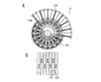
- FIG. 5B is a diagram showing the surface of the drum showing a state in which the comb teeth of the segments are engaged most deeply when the swing arm is contracted.
- FIG. 1 is a diagram schematically illustrating a tire molding apparatus including a drum according to an embodiment of the present invention.
- the tire molding apparatus is arranged concentrically within a drum 10, a rotating mechanism 20 that rotates the drum 10, and a rotating shaft (hereinafter referred to as a drum shaft) 101 of the drum 10.
- the center shaft driving mechanism 30 that reciprocates a center shaft 105 (FIG. 3), which will be described later, and a support portion 40 that supports the whole on the floor G are included.
- the rotation mechanism 20 is arbitrary as long as the drum 10 can be rotationally driven, and is a known mechanism such as a mechanism for transmitting the rotation of the drive motor to the drum shaft 101.
- the middle shaft drive mechanism 30 may use a known linear motion mechanism such as a cylinder mechanism or a screw transmission mechanism.
- the drum 10 includes a plurality of swing arms 110A that are alternately arranged at equal intervals around the drum shaft 101 and alternately in two front and rear rows along the drum shaft 101. 110B and a segment 120 attached to the tip of each swing arm 110A, 110B.
- Each segment 120 has an arcuate upper surface so that the entire segment 120 forms a circumferential surface, and comb-shaped irregularities (hereinafter referred to as comb teeth) 122 are formed at both ends of the drum circumferential direction.
- the comb teeth 122 of the adjacent segments 120 mesh with each other to form a continuous circumferential surface.
- the swing arms 110A and 110B swing at equal intervals to the slider along the circumference of the outer peripheral surface of a cylindrical slider that is fitted around the drum shaft 101, and at the other end to the segment. It is mounted movably.
- the plurality of swing arms 110A and 110B constitute independent segment expansion / contraction mechanisms, and the respective segment expansion / contraction mechanisms are arranged at intervals along the drum shaft 101 as shown in the figure.
- each segment 120 is brought into a state where the comb teeth 122 of the adjacent segments 120 are engaged with each other. While maintaining, it moves in the radial direction between the radially inner reduced position and the radially outer expanded position.
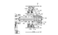
- FIG. 3 is a cross-sectional view of the drum for explaining the expansion / contraction mechanism of the drum 10.
- the upper side of FIG. 3 shows a state in which the diameter of the drum 10 is increased, and the lower side shows a state in which the diameter has been reduced.
- the drum shaft 101 is configured as a hollow tube as shown in the figure, and an intermediate shaft 105 is mounted in the hollow portion so as to be reciprocally movable by the intermediate shaft drive mechanism 30 (FIG. 1).
- the slider 140 has a cylindrical shape and is externally fitted to the drum shaft 101, and connecting portions 142 projecting inward from the inside thereof (for example, at intervals of 180 ° or 90 ° intervals along the inner periphery of the slider 140. And the number thereof is arbitrary).
- the connecting portion 142 is clamped (fixed) from both sides so as to penetrate the guide groove 102 formed along the drum shaft 101 and sandwich the large-diameter portion or the convex portion 105a of the middle shaft 105.
- FIG. 4 is an enlarged view of a main part of the drum 10 shown in FIG.
- One end portions of the swing arms 110A and 110B constituting different segment expansion / contraction mechanisms are spaced in the drum axis direction of the slider 140, and are equally spaced along the circumference and phase (angle) with respect to each other around the drum axis.
- annular body 130 that is a first fixing member serving as a fixing member is inserted into the center hole of the annular body 130 and the drum shaft 101 is inserted.
- the shaft 101 is screwed and attached integrally.
- a plurality of guide members 132 ⁇ / b> A extending in the radial direction are attached to the outer surface in the radial direction of the annular body 130 at equal intervals (equal angular intervals) with screws or the like.
- an auxiliary annular body 134 as a second fixing member having an L-shaped cross section is attached to the inner surface in the radial direction of the guide rail 132A of the annular body 130 with, for example, a screw.
- a plurality of guide rails 132B extending in the radial direction along the outer periphery thereof are attached at equal intervals (equal angular intervals) with screws or the like.
- the guide rails 132A and 132B are arranged at the same distance from the axis of the drum shaft 101.
- the L-shaped brackets 114A and 114B connected to the back surfaces of the segments 120 of the swing arms 110A and 110B by screws or the like are slidably engaged with the guide rails 132A and 132B, respectively.
- the radially outer ends (other ends) of the swing arms 110A and 110B are pivotally attached by pins 113A and 113B, respectively. Has been.
- FIG. 5A is a side view of the drum 10 of FIG. 4 as viewed from the right side in the figure.
- the upper part on the right side is a state where the swinging arms 110A and 110B are expanded, and the lower part on the left side is contracted.
- FIG. 5B is a diagram illustrating the surface of the drum 10 in a state where the comb teeth 122 of the segment 120 are engaged with each other when the swing arms 110A and 110B are contracted. In this state, the comb teeth 122 of the adjacent segments 120 are closely meshed with each other.
- the state of the comb teeth 122 of the segment 120 when the swing arms 110A and 110B are expanded is, for example, as shown in FIG. There is no gap.
- FIG. 4 shows the positions of the slider 140 and the swing arms 110A and 110B in a state where the diameter of the drum is expanded.
- adjacent ends of the swing arms 110A and 110B arranged in a line in a plane perpendicular to the direction of the drum shaft 101 along the circumference of the slider 140 are connected to each other.
- the segments 120 are alternately arranged in the front and rear rows along the direction of the drum shaft 101, and the segments 120 with the comb teeth 122 are provided at the respective leading ends (the other ends) in the radial direction.
- the segments 120 can be attached at twice the density. Therefore, the roundness when each segment 120 is expanded is improved as compared with the conventional case.
- the tire size range that can be molded can be made wider than that of the conventional drum described in Patent Document 1.
- the adjacent end portions of the one end portion of the swing arm are respectively attached to the slider so as to be swingable alternately at one of two positions spaced in the drum axis direction of the slider.
- the balance of the drum itself is stable, and it is possible to handle the molding of multiple sizes with small equipment.
- the guide member is disposed at a distance in the drum axis direction with respect to the fixed member, the expansion and contraction of the swing arm securely attached to one slider with a small number of parts and simple equipment. The effect that it is possible is also obtained.
- the swing arm has been described as having a configuration in which the swing arm is arranged in two rows in the longitudinal direction of the slider (in the drum axis direction), but is not necessarily limited thereto.
- a three-row arrangement may be used, and if the number of rows is increased, the structure becomes complicated and restrictions are imposed.
- the number of rows is increased, the number of segments can be increased accordingly, and the roundness of the drum is further improved. Therefore, the expansion / contraction stroke of the drum by the swing arm can be further increased.
- the swing arm expansion / contraction mechanism includes the fixed member (annular body 130) and the guide members (guide rails 132A and 132B), but the present invention is not limited to this.
- a well-known link mechanism for expanding and contracting the swing arm can be used.
Landscapes
- Engineering & Computer Science (AREA)
- Mechanical Engineering (AREA)
- Manufacturing & Machinery (AREA)
- Tyre Moulding (AREA)
Abstract
Description
このドラムを用いる場合、成型するタイヤの内径がセグメント間に隙間が生じない程度の大きさであれば問題はないが、当然のことながらセグメント間に隙間ができる。
セグメント間に隙間ができると、製品タイヤのユニフォーミティの欠陥或いはドラムに巻き付けたタイヤ構成部材が隙間に落ち込むなどの不具合が生じる。
そのため、1つのドラムでタイヤサイズ(内径)の異なる複数種類のタイヤ構成部材を成型することはできない。 As a molding drum, for example, a tire molding drum (hereinafter simply referred to as a drum), it is composed of a plurality of segments obtained by dividing the peripheral surface, and each segment has a distal end of a plurality of extendable arms extending radially from the central axis of the drum. It is known that a tire constituent member is molded so that no gap is generated between segments when the arm is extended.
When this drum is used, there is no problem as long as the inner diameter of the tire to be molded is a size that does not cause a gap between the segments.
If there is a gap between the segments, a defect such as a defect in the uniformity of the product tire or a tire component wound around the drum falls into the gap.
Therefore, it is impossible to mold a plurality of types of tire constituent members having different tire sizes (inner diameters) with one drum.
しかし、この方法では、ドラムを複数種類用意することのコスト面に加え、タイヤサイズの変更毎にドラムを変更する作業が発生し、それがタイヤ構成部材の成型における生産性向上の阻害要因になっている。 Therefore, conventionally, a drum that matches each tire size is prepared, and the drum is selected every time the tire size is changed.
However, in this method, in addition to the cost of preparing a plurality of types of drums, an operation of changing the drums every time the tire size is changed is an obstacle to productivity improvement in molding of tire components. ing.
請求項2の発明は、請求項1に記載された成型ドラムにおいて、前記ドラム軸に取り付けられた固定部材と、前記固定部材上において、前記揺動アームの前記他端部を前記ドラム軸の径方向に案内するための複数のガイド部材と、を有する成型ドラムである。
請求項3の発明は、請求項2に記載された成型ドラムにおいて、前記ガイド部材は、前記固定部材に対してドラム軸方向に間隔を置いて配置されている成型ドラムである。
請求項4の発明は、請求項3に記載された成型ドラムにおいて、前記固定部材は、第一の固定部材と、第一の固定部材に取り付けられ、第一の固定部材に対して軸方向に間隔を置いた第二の固定部材からなり、前記第一の固定部材は前記ドラム軸に沿って互いに隣接する前記一方のセグメント拡縮機構の揺動アームの前記他端部を案内し、前記第二の固定部材は、他方のセグメント拡縮機構の揺動アームの前記他端部を案内する成型ドラムである。
請求項5の発明は、請求項1ないし4のいずれかに記載された成型ドラムにおいて、前記スライダは前記ドラム軸のスリットを介して、前記ドラム軸中に配置された往復動する中軸に連結されている成型ドラムである。 The invention of claim 1 is an expandable / contractable molding drum having a plurality of segments constituting a circumferential surface, wherein one end portion is on the outer peripheral surface of a cylindrical slider that is externally fitted to the drum shaft, and the other end portion is The segment has a plurality of swing arms each swingably attached to the segment, and includes a plurality of segment expansion / contraction mechanisms formed by the plurality of swing arms at intervals along the drum shaft. The molding drum expands / contracts by the plurality of segment expansion / contraction mechanisms as the drum moves in the axial direction.
According to a second aspect of the present invention, there is provided the molding drum according to the first aspect, wherein a fixing member attached to the drum shaft, and the other end portion of the swing arm on the fixing member has a diameter of the drum shaft. And a plurality of guide members for guiding in a direction.
According to a third aspect of the present invention, in the molding drum according to the second aspect, the guide member is a molding drum which is disposed at an interval in the drum axial direction with respect to the fixed member.
According to a fourth aspect of the present invention, in the molding drum according to the third aspect, the fixing member is attached to the first fixing member and the first fixing member, and is in an axial direction with respect to the first fixing member. The first fixing member is configured to guide the other end of the swing arm of the one segment expansion / contraction mechanism adjacent to each other along the drum axis. The fixing member is a molding drum that guides the other end of the swing arm of the other segment expansion / contraction mechanism.
According to a fifth aspect of the present invention, in the molding drum according to any one of the first to fourth aspects, the slider is connected to a reciprocating middle shaft disposed in the drum shaft through a slit of the drum shaft. It is a molding drum.
請求項2の発明によれば、前記ドラム軸に取り付けられた固定部材上において、前記揺動アームの前記他端部を前記ドラム軸の径方向に案内するための複数のガイド部材を有するので、揺動アームをスムーズに拡縮することができると共に、ドラム軸方向の長さを、例えば揺動アームの他端にリンク機構を備えた場合に比べて短くでき、装置をコンパクト化できる。
請求項3の発明によれば、前記ガイド部材は、前記固定部材に対してドラム軸方向に間隔を置いて配置されているので、従来よりも多くの揺動アームをスムーズに拡縮することができる。
請求項4の発明によれば、前記固定部材は、第一、第二の固定部材からなり、スライダ外周方向において、前記複数の揺動アームの隣接する端部が、それぞれ、第一、第二の固定部材にガイドされるため、精度よく、揺動アームの拡縮を行う事ができ、またドラム全体の大きさをコンパクトにできる。また、簡易な設備により、多くの揺動アームの拡縮を行う事が可能である。
請求項5の発明によれば、スライダを往復動する軸(中軸)を前記ドラム軸中に配置したため、コンパクトな構成で前記スライダを摺動させることができる。 According to the first aspect of the present invention, a plurality of segment expansion / contraction mechanisms constituted by the plurality of swing arms are provided at intervals along the drum axis, and the plurality of segments are accompanied by movement of the slider in the drum axis direction. Since expansion / contraction is performed by the expansion / contraction mechanism, a plurality of rows of swing arms can be expanded / contracted with respect to one slider. As a result, even if the radial length of the swing arm is increased, there is no gap between adjacent segments, and it is possible to deal with multi-size tires while maintaining the roundness of the drum.
According to the invention of claim 2, on the fixing member attached to the drum shaft, since it has a plurality of guide members for guiding the other end portion of the swing arm in the radial direction of the drum shaft, The swing arm can be expanded and contracted smoothly, and the length in the drum axis direction can be shortened as compared with, for example, a link mechanism provided at the other end of the swing arm, and the apparatus can be made compact.
According to invention of Claim 3, since the said guide member is arrange | positioned with the space | interval in the drum axial direction with respect to the said fixing member, it can expand / contract more rocking arms more smoothly than before. .
According to a fourth aspect of the present invention, the fixing member includes first and second fixing members, and adjacent end portions of the plurality of swing arms are first and second in the slider outer peripheral direction, respectively. Therefore, the swing arm can be expanded and contracted with high accuracy, and the size of the entire drum can be made compact. In addition, it is possible to expand and contract many swing arms with simple equipment.
According to invention of
図1は、本発明の実施形態に係るドラムを備えたタイヤ成型装置を模式的に示す図である。
タイヤ成型装置は、模式的には図1に示すように、ドラム10とドラム10を回転する回転機構20と、ドラム10の回転軸(以下、ドラム軸という)101内に同心状に配置された後述する中軸105(図3)を往復移動させる中軸駆動機構30と、全体を床面G上に支持する支持部40とから成っている。
ここで、回転機構20は、ドラム10を回転駆動できるものであれば任意であり、例えば駆動モータの回転をドラム軸101に伝動する機構など周知の機構である。また、中軸駆動機構30は、例えばシリンダ機構又はネジ伝動機構などの周知の直線運動機構を用いることができる。 Next, embodiments of the present invention will be described with reference to the accompanying drawings.
FIG. 1 is a diagram schematically illustrating a tire molding apparatus including a drum according to an embodiment of the present invention.
As schematically shown in FIG. 1, the tire molding apparatus is arranged concentrically within a
Here, the
各セグメント120は、セグメント120全体で円周面を構成するように円弧状の上面を有し、そのドラム周方向側両端部には櫛歯状の凹凸(以下櫛歯という)122が形成されており、隣接するセグメント120の櫛歯122が互いに噛合して連続した前記円周面を構成する。
揺動アーム110A、110Bは、その一端部がドラム軸101に外嵌する円筒状のスライダの外周面の円周に沿って前記スライダに等間隔に、かつ他端部が前記セグメントに、それぞれ揺動可能に取り付けられている。前記複数の揺動アーム110A、110Bは、それぞれ独立したセグメント拡縮機構を構成し、それぞれのセグメント拡縮機構は、図示のように、前記ドラム軸101に沿って互いに間隔を置いて配置されている。
なお、後述するように、揺動アーム110A、110Bをドラム軸101の周りでその半径方向に揺動させることにより、各セグメント120は、隣接するセグメント120の櫛歯122同士を噛合させた状態を維持しながら、半径方向内側の縮小位置と半径方向外側の拡張位置間で半径方向に移動する。 As shown in the perspective view of FIG. 2 as a whole, the
Each
The
As will be described later, by swinging the
ドラム軸101は、図示のように中空の管体として構成されており、その中空部分に中軸105が中軸駆動機構30(図1)により往復動可能に装着されている。 FIG. 3 is a cross-sectional view of the drum for explaining the expansion / contraction mechanism of the
The
それぞれ異なるセグメント拡縮機構を構成する揺動アーム110A、110Bの一端部は、スライダ140のドラム軸方向に間隔を置き、円周に沿ってそれぞれ等間隔にかつドラム軸の回りで互いに位相(角度)をずらして、つまり互い違いになるように配置されたピン112A、112Bに枢着されている。したがって、それぞれ異なるセグメント拡縮機構を構成する揺動アーム110A、110Bは、スライダ140の周面に沿って等間隔に、かつ揺動アーム110A、110Bのスライダ140に枢着された一端部は、ドラム軸方向において前後に互い違いに配置される。 FIG. 4 is an enlarged view of a main part of the
One end portions of the
図5Bは揺動アーム110A、110Bが縮閉したときのセグメント120の櫛歯122が互いに最も深く噛合した状態を示すドラム10の表面を示す図である。この状態では隣接するセグメント120の櫛歯122は互いに密に噛合している。揺動アーム110A、110Bが拡開したときのセグメント120の櫛歯122の状態は、例えば図2に示すように、隣接するセグメント120の櫛歯122間には隙間ができるが、セグメント120間には隙間ができていない状態になっている。 FIG. 5A is a side view of the
FIG. 5B is a diagram illustrating the surface of the
スライダ140の左方への移動により、揺動アーム110A、110Bのピン112A、112Bとの枢着端(一端部)は左側に移動するが、揺動アーム110A、110Bの半径方向先端部(他端部)は、L形ブラケット114A、114Bを介して、ドラム軸101に固定された環状体130及び補助環状体134のガイドレール132A、132Bに係合しているため左方への移動は阻止されている。その結果、揺動アーム110A、110Bの半径方向先端部は、ガイドレール132A、132Bに沿って半径方向外側に向かって移動(摺動)する。 In the above configuration, when the middle
As the
したがって、各セグメント120の拡開したときの真円度が従来よりも向上する。そのため、従来よりも大きく拡開しても、つまり、ドラム10の拡縮ストロークを従来よりも大きくしても、各セグメント120の必要な真円度を維持することができ、内径のより大きなタイヤの成型にも用いることができる。 According to this embodiment, conventionally, adjacent ends of the
Therefore, the roundness when each
また、前記揺動アームの一端部の隣接端部同士は、それぞれ、前記スライダのドラム軸方向において間隔を置いた二つの位置のいずれかで前記スライダに交互に揺動可能に取り付けられているため、ドラム自体のバランスが安定し、かつ小設備で多サイズのタイヤ成型に対応できる。 According to this embodiment, since the number of segments is doubled with respect to the conventional drum, the tire size range that can be molded can be made wider than that of the conventional drum described in Patent Document 1.
Further, the adjacent end portions of the one end portion of the swing arm are respectively attached to the slider so as to be swingable alternately at one of two positions spaced in the drum axis direction of the slider. The balance of the drum itself is stable, and it is possible to handle the molding of multiple sizes with small equipment.
例えば、3列配置でもよく、列数を増やすと構造が複雑になるため制約が出てくるが、列数を増やせばそれだけセグメント数を増やすことができ、ドラムの真円度が一層向上する。したがって揺動アームによるドラムの拡縮ストロークをより一層長くすることができる。 In the above description, the swing arm has been described as having a configuration in which the swing arm is arranged in two rows in the longitudinal direction of the slider (in the drum axis direction), but is not necessarily limited thereto.
For example, a three-row arrangement may be used, and if the number of rows is increased, the structure becomes complicated and restrictions are imposed. However, if the number of rows is increased, the number of segments can be increased accordingly, and the roundness of the drum is further improved. Therefore, the expansion / contraction stroke of the drum by the swing arm can be further increased.
Claims (5)
- 円周面を構成する複数のセグメントを有する拡縮可能な成型ドラムであって、
一端部がドラム軸に外嵌する円筒状のスライダの外周面に、かつ他端部が前記セグメントに、それぞれ揺動可能に取り付けられた複数の揺動アームを有し、前記複数の揺動アームで構成するセグメント拡縮機構を前記ドラム軸に沿って間隔を置いて複数備え、前記スライダのドラム軸方向の移動に伴って前記複数のセグメント拡縮機構により拡縮する成型ドラム。 An expansion / contraction molding drum having a plurality of segments constituting a circumferential surface,
The plurality of oscillating arms each having a plurality of oscillating arms attached to an outer peripheral surface of a cylindrical slider whose one end is externally fitted to the drum shaft and the other end to the segment. A molding drum comprising a plurality of segment expansion / contraction mechanisms arranged at intervals along the drum axis, wherein the plurality of segment expansion / contraction mechanisms are expanded and contracted as the slider moves in the drum axis direction. - 請求項1に記載された成型ドラムにおいて、
前記ドラム軸に取り付けられた固定部材と、
前記固定部材上において、前記揺動アームの前記他端部を前記ドラム軸の径方向に案内するための複数のガイド部材と、を有する成型ドラム。 The molding drum according to claim 1,
A fixing member attached to the drum shaft;
A molding drum having a plurality of guide members for guiding the other end of the swing arm in a radial direction of the drum shaft on the fixed member. - 請求項2に記載された成型ドラムにおいて、
前記ガイド部材は、前記固定部材に対してドラム軸方向に間隔を置いて配置されている成型ドラム。 The molding drum according to claim 2,
The said guide member is a shaping | molding drum arrange | positioned at intervals in the drum axial direction with respect to the said fixing member. - 請求項3に記載された成型ドラムにおいて、
前記固定部材は、第一の固定部材と、第一の固定部材に取り付けられ、第一の固定部材に対して軸方向に間隔を置いた第二の固定部材からなり、
前記第一の固定部材は前記ドラム軸に沿って互いに隣接する一方のセグメント拡縮機構の揺動アームの前記他端部を案内し、前記第二の固定部材は、他方のセグメント拡縮機構の揺動アームの前記他端部を案内する成型ドラム。 The molding drum according to claim 3,
The fixing member includes a first fixing member and a second fixing member attached to the first fixing member and spaced in the axial direction with respect to the first fixing member.
The first fixing member guides the other end of the swing arm of one segment expansion / contraction mechanism adjacent to each other along the drum axis, and the second fixing member swings the other segment expansion / contraction mechanism. A molding drum for guiding the other end of the arm. - 請求項1ないし4のいずれかに記載された成型ドラムにおいて、
前記スライダは前記ドラム軸のスリットを介して、前記ドラム軸中に配置された往復動する中軸に連結されている成型ドラム。 In the molding drum according to any one of claims 1 to 4,
The slider is a molding drum connected to a reciprocating middle shaft disposed in the drum shaft through a slit of the drum shaft.
Priority Applications (4)
| Application Number | Priority Date | Filing Date | Title |
|---|---|---|---|
| RU2015143205A RU2625238C2 (en) | 2013-03-12 | 2014-02-26 | Forming reel |
| EP14763014.9A EP2974853B1 (en) | 2013-03-12 | 2014-02-26 | Molding drum |
| US14/771,641 US10279555B2 (en) | 2013-03-12 | 2014-02-26 | Molding drum |
| CN201480014351.6A CN105073396B (en) | 2013-03-12 | 2014-02-26 | Assembly drum |
Applications Claiming Priority (2)
| Application Number | Priority Date | Filing Date | Title |
|---|---|---|---|
| JP2013-049496 | 2013-03-12 | ||
| JP2013049496A JP5579295B1 (en) | 2013-03-12 | 2013-03-12 | Molding drum |
Publications (1)
| Publication Number | Publication Date |
|---|---|
| WO2014141885A1 true WO2014141885A1 (en) | 2014-09-18 |
Family
ID=51536560
Family Applications (1)
| Application Number | Title | Priority Date | Filing Date |
|---|---|---|---|
| PCT/JP2014/054769 WO2014141885A1 (en) | 2013-03-12 | 2014-02-26 | Molding drum |
Country Status (6)
| Country | Link |
|---|---|
| US (1) | US10279555B2 (en) |
| EP (1) | EP2974853B1 (en) |
| JP (1) | JP5579295B1 (en) |
| CN (1) | CN105073396B (en) |
| RU (1) | RU2625238C2 (en) |
| WO (1) | WO2014141885A1 (en) |
Cited By (1)
| Publication number | Priority date | Publication date | Assignee | Title |
|---|---|---|---|---|
| CN106584897A (en) * | 2016-12-26 | 2017-04-26 | 桂林橡胶机械有限公司 | Spindle drive device of tyre forming machine |
Families Citing this family (4)
| Publication number | Priority date | Publication date | Assignee | Title |
|---|---|---|---|---|
| JP7081156B2 (en) * | 2018-01-10 | 2022-06-07 | 住友ゴム工業株式会社 | Tire molding machine |
| CN111016241A (en) * | 2019-12-30 | 2020-04-17 | 山东丰源轮胎制造股份有限公司 | Adjustable cushion block for BT drum of tire one-step forming machine |
| CN113290900A (en) * | 2021-06-16 | 2021-08-24 | 北京化工大学 | Double-nut-driven tire vulcanization inner mold |
| CN113878913A (en) * | 2021-10-12 | 2022-01-04 | 天津赛象科技股份有限公司 | Child embryo section of thick bamboo forming device |
Citations (8)
| Publication number | Priority date | Publication date | Assignee | Title |
|---|---|---|---|---|
| JPS4925075A (en) * | 1972-06-28 | 1974-03-06 | ||
| JPS50157477A (en) * | 1974-06-13 | 1975-12-19 | ||
| JPS5591646A (en) * | 1978-12-29 | 1980-07-11 | Bridgestone Corp | Center alignment device for annular member |
| JPH06344465A (en) | 1993-06-11 | 1994-12-20 | Sumitomo Rubber Ind Ltd | Apparatus for molding tire reinforcing structure body |
| JP2002028986A (en) * | 2000-07-13 | 2002-01-29 | Fuji Seiko Kk | Drum for molding tire |
| JP2004520194A (en) * | 2001-01-15 | 2004-07-08 | ソシエテ ド テクノロジー ミシュラン | Modeling drum for tire carcass |
| WO2010140485A1 (en) * | 2009-06-01 | 2010-12-09 | 株式会社ブリヂストン | Tire building drum and device and method for production of unvulcanized tires |
| US20120168087A1 (en) * | 2010-12-31 | 2012-07-05 | BPS Engineering, LLC. | Assembly for altering the diameter of transfer ring or drum apparatus through a broad range |
Family Cites Families (18)
| Publication number | Priority date | Publication date | Assignee | Title |
|---|---|---|---|---|
| US3761340A (en) * | 1971-04-12 | 1973-09-25 | Deering Milliken Res Corp | Adjustable automatic tire belt doffer |
| SU483279A2 (en) | 1974-04-10 | 1975-09-05 | Всесоюзный Научно-Исследовательский И Конструкторский Институт По Оборудованию Для Шинной Промышленности | Drum to machine for two-stage assembly of tires pneumatic tires |
| JPS5157334A (en) * | 1974-11-15 | 1976-05-19 | Mitsubishi Motors Corp | HAIGASUJOKAYONIJIKUKIDONYUSOCHI |
| SU555615A1 (en) | 1975-08-11 | 1991-03-07 | Научно-Исследовательский, Конструкторско-Технологический Институт Шинной Промышленности | Drum for assembling and forming pneumatic tyres |
| JPS5357283A (en) * | 1976-11-04 | 1978-05-24 | Bridgestone Tire Co Ltd | Tire molding drum |
| US4268330A (en) | 1978-12-29 | 1981-05-19 | Bridgestone Tire Company Limited | Green tire building process and apparatus |
| JPS59120438A (en) | 1982-12-27 | 1984-07-12 | Bridgestone Corp | Tire molding equipment |
| JPS59216702A (en) * | 1983-05-24 | 1984-12-06 | Sumitomo Rubber Ind Ltd | Tire holding rim device |
| JPS6157334A (en) * | 1984-08-29 | 1986-03-24 | Yokohama Rubber Co Ltd:The | Molding drum |
| SU1735045A1 (en) | 1990-04-09 | 1992-05-23 | Омское научно-производственное объединение "Прогресс" | Device for moulding pneumatic tire covers |
| JPH0757537B2 (en) * | 1991-03-20 | 1995-06-21 | 株式会社森鐵工所 | Device for driving movable part in tire building drum device and tire building drum device using the same |
| US5618374A (en) * | 1994-02-10 | 1997-04-08 | Wyko, Inc. | Belt and tread drum for vehicle tire making machine |
| JP4448230B2 (en) * | 2000-05-09 | 2010-04-07 | 住友ゴム工業株式会社 | Belt forming device |
| US20040244914A1 (en) * | 2003-06-09 | 2004-12-09 | Wyko, Inc. | Collapsible shaping drum |
| JP4474343B2 (en) * | 2005-08-04 | 2010-06-02 | 不二精工株式会社 | Rubber sheet joining method and joining apparatus |
| JP4510907B2 (en) * | 2008-05-16 | 2010-07-28 | 住友ゴム工業株式会社 | Tire member molding drum |
| US20120007372A1 (en) * | 2010-07-07 | 2012-01-12 | Nurmi Kurt E | Vehicle latch with over travel stop feature |
| JP5619502B2 (en) * | 2010-07-21 | 2014-11-05 | 株式会社ブリヂストン | Tire molding equipment |
-
2013
- 2013-03-12 JP JP2013049496A patent/JP5579295B1/en not_active Expired - Fee Related
-
2014
- 2014-02-26 EP EP14763014.9A patent/EP2974853B1/en not_active Not-in-force
- 2014-02-26 RU RU2015143205A patent/RU2625238C2/en active
- 2014-02-26 US US14/771,641 patent/US10279555B2/en active Active
- 2014-02-26 CN CN201480014351.6A patent/CN105073396B/en not_active Expired - Fee Related
- 2014-02-26 WO PCT/JP2014/054769 patent/WO2014141885A1/en active Application Filing
Patent Citations (8)
| Publication number | Priority date | Publication date | Assignee | Title |
|---|---|---|---|---|
| JPS4925075A (en) * | 1972-06-28 | 1974-03-06 | ||
| JPS50157477A (en) * | 1974-06-13 | 1975-12-19 | ||
| JPS5591646A (en) * | 1978-12-29 | 1980-07-11 | Bridgestone Corp | Center alignment device for annular member |
| JPH06344465A (en) | 1993-06-11 | 1994-12-20 | Sumitomo Rubber Ind Ltd | Apparatus for molding tire reinforcing structure body |
| JP2002028986A (en) * | 2000-07-13 | 2002-01-29 | Fuji Seiko Kk | Drum for molding tire |
| JP2004520194A (en) * | 2001-01-15 | 2004-07-08 | ソシエテ ド テクノロジー ミシュラン | Modeling drum for tire carcass |
| WO2010140485A1 (en) * | 2009-06-01 | 2010-12-09 | 株式会社ブリヂストン | Tire building drum and device and method for production of unvulcanized tires |
| US20120168087A1 (en) * | 2010-12-31 | 2012-07-05 | BPS Engineering, LLC. | Assembly for altering the diameter of transfer ring or drum apparatus through a broad range |
Cited By (1)
| Publication number | Priority date | Publication date | Assignee | Title |
|---|---|---|---|---|
| CN106584897A (en) * | 2016-12-26 | 2017-04-26 | 桂林橡胶机械有限公司 | Spindle drive device of tyre forming machine |
Also Published As
| Publication number | Publication date |
|---|---|
| EP2974853A1 (en) | 2016-01-20 |
| EP2974853A4 (en) | 2016-03-09 |
| RU2015143205A (en) | 2017-04-17 |
| US10279555B2 (en) | 2019-05-07 |
| RU2625238C2 (en) | 2017-07-12 |
| JP5579295B1 (en) | 2014-08-27 |
| EP2974853B1 (en) | 2017-09-06 |
| CN105073396B (en) | 2017-07-25 |
| CN105073396A (en) | 2015-11-18 |
| JP2014172361A (en) | 2014-09-22 |
| US20160023415A1 (en) | 2016-01-28 |
Similar Documents
| Publication | Publication Date | Title |
|---|---|---|
| WO2014141885A1 (en) | Molding drum | |
| JP5220103B2 (en) | Bead wire winding and forming device | |
| JP6516867B2 (en) | Knitting machine | |
| US6390166B1 (en) | Expandable mandrel having adjustable width | |
| KR102135730B1 (en) | Tire forming drum | |
| JP2007136935A (en) | Rigid body segment for tire molding drum and tire molding drum using it | |
| JP6587525B2 (en) | Tire molding drum | |
| JP2018514423A (en) | Tire manufacturing drum | |
| JP6305527B2 (en) | Leisure mechanism for rod making machine | |
| JP2013018274A (en) | Method and device for gripping annular body | |
| JP2013226677A (en) | Apparatus and method for winding band-shaped member | |
| JP5283706B2 (en) | Bead manufacturing method and manufacturing apparatus | |
| JP6587524B2 (en) | Tire molding equipment | |
| JP2009012218A (en) | Bead set apparatus and tire molding machine | |
| JP4763940B2 (en) | Tire belt layer forming device | |
| JP7354751B2 (en) | Tire component forming equipment | |
| JP2015184678A (en) | optical device | |
| CN219486653U (en) | Tire molding tire bead lock ring device | |
| JP4467325B2 (en) | Tire molding machine | |
| JP6900304B2 (en) | Tire molding equipment | |
| RU2296050C1 (en) | Mandrel for continuous winding of tubes | |
| CN107626940B (en) | Positioning device for forming plastic parts of drum of washing machine | |
| JP5569967B2 (en) | Unvulcanized tire molding apparatus and molding method | |
| JP2902023B2 (en) | Endless belt molding equipment | |
| JP2012035452A (en) | Carrying device |
Legal Events
| Date | Code | Title | Description |
|---|---|---|---|
| WWE | Wipo information: entry into national phase |
Ref document number: 201480014351.6 Country of ref document: CN |
|
| 121 | Ep: the epo has been informed by wipo that ep was designated in this application |
Ref document number: 14763014 Country of ref document: EP Kind code of ref document: A1 |
|
| WWE | Wipo information: entry into national phase |
Ref document number: 14771641 Country of ref document: US |
|
| NENP | Non-entry into the national phase |
Ref country code: DE |
|
| REEP | Request for entry into the european phase |
Ref document number: 2014763014 Country of ref document: EP |
|
| WWE | Wipo information: entry into national phase |
Ref document number: 2014763014 Country of ref document: EP |
|
| ENP | Entry into the national phase |
Ref document number: 2015143205 Country of ref document: RU Kind code of ref document: A |