WO2014141791A1 - ガスタービン用サイレンサ、及びそれを備えたガスタービン - Google Patents
ガスタービン用サイレンサ、及びそれを備えたガスタービン Download PDFInfo
- Publication number
- WO2014141791A1 WO2014141791A1 PCT/JP2014/053036 JP2014053036W WO2014141791A1 WO 2014141791 A1 WO2014141791 A1 WO 2014141791A1 JP 2014053036 W JP2014053036 W JP 2014053036W WO 2014141791 A1 WO2014141791 A1 WO 2014141791A1
- Authority
- WO
- WIPO (PCT)
- Prior art keywords
- silencer
- silencer panel
- panel
- upstream
- downstream
- Prior art date
- Legal status (The legal status is an assumption and is not a legal conclusion. Google has not performed a legal analysis and makes no representation as to the accuracy of the status listed.)
- Ceased
Links
Images






Classifications
-
- F—MECHANICAL ENGINEERING; LIGHTING; HEATING; WEAPONS; BLASTING
- F02—COMBUSTION ENGINES; HOT-GAS OR COMBUSTION-PRODUCT ENGINE PLANTS
- F02C—GAS-TURBINE PLANTS; AIR INTAKES FOR JET-PROPULSION PLANTS; CONTROLLING FUEL SUPPLY IN AIR-BREATHING JET-PROPULSION PLANTS
- F02C7/00—Features, components parts, details or accessories, not provided for in, or of interest apart form groups F02C1/00 - F02C6/00; Air intakes for jet-propulsion plants
- F02C7/24—Heat or noise insulation
-
- F—MECHANICAL ENGINEERING; LIGHTING; HEATING; WEAPONS; BLASTING
- F01—MACHINES OR ENGINES IN GENERAL; ENGINE PLANTS IN GENERAL; STEAM ENGINES
- F01D—NON-POSITIVE DISPLACEMENT MACHINES OR ENGINES, e.g. STEAM TURBINES
- F01D25/00—Component parts, details, or accessories, not provided for in, or of interest apart from, other groups
- F01D25/30—Exhaust heads, chambers, or the like
-
- F—MECHANICAL ENGINEERING; LIGHTING; HEATING; WEAPONS; BLASTING
- F02—COMBUSTION ENGINES; HOT-GAS OR COMBUSTION-PRODUCT ENGINE PLANTS
- F02C—GAS-TURBINE PLANTS; AIR INTAKES FOR JET-PROPULSION PLANTS; CONTROLLING FUEL SUPPLY IN AIR-BREATHING JET-PROPULSION PLANTS
- F02C3/00—Gas-turbine plants characterised by the use of combustion products as the working fluid
- F02C3/04—Gas-turbine plants characterised by the use of combustion products as the working fluid having a turbine driving a compressor
-
- F—MECHANICAL ENGINEERING; LIGHTING; HEATING; WEAPONS; BLASTING
- F02—COMBUSTION ENGINES; HOT-GAS OR COMBUSTION-PRODUCT ENGINE PLANTS
- F02C—GAS-TURBINE PLANTS; AIR INTAKES FOR JET-PROPULSION PLANTS; CONTROLLING FUEL SUPPLY IN AIR-BREATHING JET-PROPULSION PLANTS
- F02C7/00—Features, components parts, details or accessories, not provided for in, or of interest apart form groups F02C1/00 - F02C6/00; Air intakes for jet-propulsion plants
- F02C7/04—Air intakes for gas-turbine plants or jet-propulsion plants
- F02C7/045—Air intakes for gas-turbine plants or jet-propulsion plants having provisions for noise suppression
-
- B—PERFORMING OPERATIONS; TRANSPORTING
- B64—AIRCRAFT; AVIATION; COSMONAUTICS
- B64D—EQUIPMENT FOR FITTING IN OR TO AIRCRAFT; FLIGHT SUITS; PARACHUTES; ARRANGEMENT OR MOUNTING OF POWER PLANTS OR PROPULSION TRANSMISSIONS IN AIRCRAFT
- B64D33/00—Arrangement in aircraft of power plant parts or auxiliaries not otherwise provided for
- B64D33/02—Arrangement in aircraft of power plant parts or auxiliaries not otherwise provided for of combustion air intakes
- B64D2033/0206—Arrangement in aircraft of power plant parts or auxiliaries not otherwise provided for of combustion air intakes comprising noise reduction means, e.g. acoustic liners
-
- F—MECHANICAL ENGINEERING; LIGHTING; HEATING; WEAPONS; BLASTING
- F05—INDEXING SCHEMES RELATING TO ENGINES OR PUMPS IN VARIOUS SUBCLASSES OF CLASSES F01-F04
- F05D—INDEXING SCHEME FOR ASPECTS RELATING TO NON-POSITIVE-DISPLACEMENT MACHINES OR ENGINES, GAS-TURBINES OR JET-PROPULSION PLANTS
- F05D2260/00—Function
- F05D2260/96—Preventing, counteracting or reducing vibration or noise
Definitions
- the present invention relates to a silencer for a gas turbine provided on the intake side of a compressor of a gas turbine.
- a silencer structure there is a structure in which a plurality of silencer panels are arranged in parallel so that their plate surfaces are parallel to the air flow direction.
- the silencer panel is necessary to divide the silencer panel in the direction of airflow from the viewpoint of manufacturing or transportation restrictions.
- the manufacturing accuracy of the length in the air flow direction of the upstream silencer panel and the downstream silencer panel is lowered, and there is a great possibility that a gap is generated between the two panels. If there is a gap between the upstream silencer panel and the downstream silencer panel, the air flowing from the upstream side enters the gap, creating an air flow vortex, generating pressure loss, and the original air flow. There is a possibility that secondary noise will be generated, which is different from the noise associated with.
- Patent Document 1 discloses an opening end of a gap adjustment cover having a U-shaped cross section from the side of the upstream side silencer panel and the downstream side silencer panel facing the other silencer panel. There is described a silencer in which is fitted and fixed. With this configuration, the gap between one silencer panel to which the gap adjustment cover is fixed and the other silencer panel is substantially reduced due to the thermal expansion of the silencer panel material due to heat generated when air flows. I try to make it zero.
- the gap adjustment cover is fitted and fixed from the open end to one of the silencer panel on the upstream side and the silencer panel on the downstream side, the gap adjustment cover is attached to the plate surface of the silencer panel. A level difference due to will occur. This level difference may disturb the air flow and possibly cause secondary noise.
- the present invention has been made to solve the above-described problems, and avoids the generation of a gap between the upstream silencer panel and the downstream silencer panel, thereby generating secondary noise. It aims at providing the silencer for gas turbines to suppress, and a gas turbine provided with the same.
- a silencer for a gas turbine according to the present invention for solving the above problem is a silencer for a gas turbine installed between an air intake port of a gas turbine and a compressor.
- a plurality of flat panel-shaped divided silencer panels arranged in parallel at a predetermined interval in a direction perpendicular to the direction of fluid flow toward the compressor, and the divided-type silencer panel has a surface with the largest flat plate area,
- An upstream silencer panel disposed upstream of the upstream silencer panel in the fluid flow direction, and disposed upstream of the upstream silencer panel, the upstream silencer being disposed in a direction along the fluid flow;
- a downstream silencer panel connected to the panel, and one of the upstream silencer panel and the downstream silencer panel is the other silencer panel
- An opening is formed on the side facing the silencer panel, the other silencer panel is formed with a fitting portion that fits into the opening, and the fitting portion of the other silencer panel is the one
- the surface of the one silencer panel and the other silencer panel in contact with the fluid is substantially flush. Is preferred.
- the other silencer panel has a closed end at which the fitting portion is formed, and has a convex shape in a direction in which the fitting portion is fitted to the one silencer panel.
- This configuration simplifies the structure because there is no need to provide an opening in the mating portion of the other silencer panel. For this reason, the manufacturing precision of a split-type silencer panel can be improved.
- the one silencer panel has a predetermined length from the end on the opening side toward the inside as a base point, and from the base point toward the end on the opening side, the split silencer panel
- the lengths of the openings in the juxtaposed direction gradually increase, and the other silencer panel is based on the position of the predetermined length from the end portion on the fitting portion side, and on the end portion on the fitting portion side.
- it is preferable that the length of the fitting portion in the juxtaposed direction is gradually reduced to form the fitting portion.
- This configuration makes it easier to assemble the fitting part of the other silencer panel into the opening of one silencer panel, thus improving the manufacturing workability.
- the space that does not need to be filled with the sound absorbing material is reduced, the silencing performance of the gas turbine silencer is improved.
- the fitting portion is fitted over substantially the entire area of the opening of the one silencer panel.
- This configuration can improve the connection strength between the upstream silencer panel and the downstream silencer panel.
- the fitting part of the other silencer panel is fitted in a part of the opening of the one silencer panel.
- This configuration makes it possible to increase the area where the sound absorbing material can be filled, so that the silencing performance of the divided silencer can be improved.
- the other silencer panel has a plurality of fitting portions.
- This configuration ensures sufficient connection strength between the upstream silencer panel and the downstream silencer panel.
- the divided silencer panel has a hollow box shape inside, a plurality of fine holes are formed on a side surface in contact with the fluid, and the cavity is filled with a sound absorbing material.
- the air that has entered the divided silencer panel has a predetermined viscous action, and further, noise due to the air flow is reduced by the sound absorbing action of the sound absorbing material.
- the gas turbine according to the present invention for solving the above-described problems is the compressor for compressing the air taken in from the air intake port, and the fuel is supplied to the compressed air compressed by the compressor,
- a combustor that generates combustion gas by ignition and combustion; a turbine section that generates rotational power in a rotor by the combustion gas; an exhaust chamber that discharges the combustion gas that has passed through the turbine section; and the air intake
- the gas turbine silencer described above is provided between the inlet and the compressor.
- This configuration can reduce noise associated with the flow of air sucked into the compressor or noise associated with the flow of combustion gas passing through the exhaust chamber.
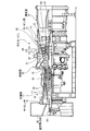
- FIG. 1 is a schematic configuration diagram of a gas turbine according to Embodiment 1 of the present invention.
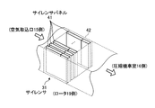
- FIG. 2 is an external perspective view of the silencer according to the first embodiment.
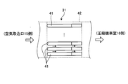
- FIG. 3 is a configuration diagram of the silencer rotor according to the first embodiment when viewed in the radial direction.
- FIG. 4 is an external perspective view of the silencer panel according to the first embodiment.
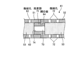
- FIG. 5 is a configuration diagram of a fitting portion of the silencer panel in the AA cross section of FIG.
- FIG. 6 is a side view of the main part of the silencer panel of the first embodiment.
- FIG. 7 is a sectional view (corresponding to a sectional view taken along the line AA) in the radial direction of the rotor of the silencer panel constituting the silencer according to the second embodiment of the present invention.
- FIG. 8 is a side view of a main part of the silencer panel according to the second embodiment.
- FIG. 9 is a sectional view (corresponding to a sectional view taken along the line AA) in the radial direction of the rotor of the silencer panel constituting the silencer according to the third embodiment of the present invention.
- FIG. 10 is a side view of an essential part of the silencer panel according to the third embodiment.
- FIG. 11 is a principal part side view of the silencer panel which comprises the silencer which concerns on Example 4 of this invention.
- 12 is a configuration diagram of a fitting portion of the silencer panel in the BB cross section of FIG.
- FIG. 13 is a configuration diagram of a contact portion of the silencer panel in the CC section of FIG.
- FIG. 1 is a schematic configuration diagram of a gas turbine according to Embodiment 1 of the present invention. A schematic configuration of a gas turbine 1 according to the present embodiment will be described with reference to FIG.
- the gas turbine 1 includes a compressor 11, a combustor 12, a turbine section 13, and an exhaust chamber 14, as shown in FIG. Further, a rotor 19 is disposed through the central portion of the compressor 11, the combustor 12, the turbine unit 13, and the exhaust chamber 14. A drive shaft of a generator (not shown) is connected to the end of the rotor 19 on the exhaust chamber 14 side.
- the compressor 11 includes an air intake port 15 for taking in external air, a plurality of stationary blades 17 and moving blades 18 arranged alternately in the compressor casing 16, an air intake port 15, and the compressor casing 16. And a silencer 31 installed between the two.
- the compressor 11 is a mechanism that compresses external air taken from the air intake port 15 to generate high-temperature and high-pressure compressed air.
- the stationary blade 17 is fixed to the inner wall surface of the compressor casing 16 along the circumferential direction of the rotor 19.
- the rotor blade 18 is fixed along the circumferential direction of the rotor 19 to the outer periphery of a disk-shaped disk formed on the rotor 19 in the compressor casing 16.
- the combustor 12 is a device that supplies fuel to the compressed air generated by the compressor 11 and ignites and burns it with a burner to generate combustion gas.
- the turbine unit 13 includes a plurality of turbine stationary blades 21 and turbine rotor blades 22 that are alternately disposed in the turbine casing 20.
- the turbine unit 13 is a mechanism that generates rotational power in the rotor 19 by the combustion gas that is the working fluid generated by the combustor 12.
- the turbine stationary blade 21 is fixed to the inner wall surface of the turbine casing 20 along the circumferential direction of the rotor 19.
- the turbine rotor blade 22 is fixed along the circumferential direction of the rotor 19 to the outer periphery of a disk-shaped disk formed on the rotor 19 in the turbine casing 20.
- the exhaust chamber 14 has an exhaust diffuser 23 that communicates with the turbine casing 20 of the turbine section 13.
- the exhaust chamber 14 discharges the combustion gas that has passed through the turbine casing 20 in which the turbine stationary blades 21 and the turbine rotor blades 22 are alternately arranged to the outside.
- the rotor 19 has an end portion on the compressor 11 side supported rotatably by a bearing portion 26, and an end portion on the exhaust chamber 14 side supported rotatably by a bearing portion 27.
- the air taken in from the air intake port 15 is reduced in noise due to the air flow by the silencer 31 and flows into the compressor casing 16 of the compressor 11.
- the air that has flowed into the compressor casing 16 passes through a plurality of stationary blades 17 and moving blades 18 that are alternately arranged to become compressed air that has been compressed to a high temperature and a high pressure.
- the combustor 12 supplies fuel to the compressed air, and ignites and burns to generate high-temperature and high-pressure combustion gas.
- the combustion gas as the working fluid passes through a plurality of turbine stationary blades 21 and turbine rotor blades 22 alternately arranged in the turbine casing 20, whereby the rotor 19 rotates and is connected to the rotor 19.
- a generator is driven to generate electricity.
- the combustion gas that has passed through the turbine casing 20 is converted into a static pressure by the exhaust diffuser 23 in the exhaust chamber 14 and then released to the outside as exhaust gas.
- FIG. 2 is an external perspective view of the silencer according to the first embodiment.
- FIG. 3 is a configuration diagram of the silencer rotor according to the first embodiment when viewed in the radial direction. The structure of the silencer 31 will be described with reference to FIGS. 2 and 3.
- the silencer 31 includes a plurality of flat silencer panels (split silencer panels) 41 in the duct 42 between the air intake port 15 and the compressor casing 16, and the plate surface is compressed from the air intake port 15. Along the direction of the air flow toward the machine compartment 16 and along the circumferential direction of the rotor 19, they are arranged in parallel at predetermined intervals.
- 2 shows a part of the silencer 31 in which a plurality of silencer panels 41 are juxtaposed in the duct 42
- FIGS. 2 and 3 show the radial direction of the rotor 19 in order to show the internal structure of the silencer 31.
- FIG. The state where the visual duct 42 portion is excluded is shown.
- the external air taken in from the air intake port 15 flows to the compressor compartment 16 side through a gap between the silencer panels 41 arranged in parallel by the silencer 31.
- FIG. 4 is an external perspective view of the silencer panel according to the first embodiment.
- FIG. 5 is a configuration diagram of a fitting portion of the silencer panel in the AA cross section of FIG.
- FIG. 6 is a side view of the main part of the silencer panel according to the first embodiment. The structure of the silencer panel 41 and the fitting structure between the upstream silencer panel 51 and the downstream silencer panel 52 will be described with reference to FIGS.
- FIG. 4 shows the appearance of the silencer panel 41 arranged in parallel in the duct 42 described above.
- the silencer panel 41 is a metal panel having a structure that can be divided in the direction of air flow.
- the upstream part is an upstream silencer panel (upstream silencer panel) 51, and the downstream part is downstream.
- a silencer panel (downstream silencer panel) 52 is used.
- the upstream-side silencer panel 51 is a formed box-shaped object having an opening 64 that is open on the side to be fitted with the downstream-side silencer panel 52, and the inside is hollow as shown in FIG. Further, the upstream silencer panel 51 has a streamlined bull nose 61 formed in the upstream portion of the air flow.
- the downstream-side silencer panel 52 is a box-shaped object having an opening 74 opened on the side to be fitted with the upstream-side silencer panel 51, and the inside is hollow as shown in FIG.
- each cavity of the upstream side silencer panel 51 and the downstream side silencer panel 52 is filled with a sound absorbing material 53 made of a porous material having a sound absorbing property.
- the porous material include inorganic fiber materials such as glass wool, polymer fiber materials such as polyester, and resin foam materials such as foamed soft urethane.
- a plurality of fine holes 62 are formed in the side surface through which air passes in the upstream silencer panel 51.
- a plurality of fine holes 72 are formed in a side surface through which air passes in the downstream silencer panel 52.
- a stepped portion in which the length of the silencer panel 41 in the juxtaposed direction (hereinafter simply referred to as the width direction) is reduced at the opening side portion of the downstream silencer panel 52.
- 71 is formed.
- the stepped portion 71 is fitted over substantially the entire area within the opening 64 of the upstream silencer panel 51, whereby the upstream silencer panel 51 and the downstream silencer panel 52 are connected.
- the side surfaces of the connected upstream silencer panel 51 and downstream silencer panel 52 are substantially flush.
- fine holes 62 and 72 are not formed in the side surface of the portion where the stepped portion 71 of the upstream silencer panel 51 is fitted and the side surface of the stepped portion 71 of the downstream silencer panel 52, respectively.
- the cavity corresponding to the side surface where the micro holes 62 and 72 are not formed that is, the cavity 73 corresponding to the stepped portion 71 of the downstream silencer panel 52 is provided.
- the sound absorbing material 53 is not filled. This is because even if the sound absorbing material 53 is filled in the cavity corresponding to the side portion where the fine holes are not drilled, it does not contribute to the reduction of noise caused by the air flow.
- the air taken in from the air intake port 15 passes through a gap between the silencer panels 41 arranged in parallel in the circumferential direction of the rotor 19 in the silencer 31.
- the air passing through the gap between the silencer panels 41 passes through the fine holes 62 and 72 formed in the side surface of the silencer panel 41 and enters the silencer panel 41.
- the air that has entered the inside of the silencer panel 41 is the width of the cavity in the width direction inside the silencer panel 41, the aperture ratio of the fine holes 62 and 72 in the side surface of the silencer panel 41, the plate thickness of the side surface of the silencer panel 41, and the fineness. Viscous action occurs due to the correlation between the hole diameters of the holes 62 and 72.
- a predetermined sound absorption characteristic is obtained by the viscous action of the air.
- the air that has entered the silencer panel 41 is further absorbed by the sound absorbing material 53 filled therein.
- the noise caused by the air flow is reduced by the action of the silencer 31 described above.
- the stepped portion 71 of the downstream silencer panel 52 is fitted over substantially the entire area within the opening 64 of the upstream silencer panel 51, whereby the upstream silencer panel 51 and the downstream side The silencer panel 52 is connected.
- this configuration there is no gap between the upstream silencer panel 51 and the downstream silencer panel 52, so there is no air flow vortex and pressure loss and secondary noise are generated. Can be prevented.
- the stepped portion 71 is fitted over substantially the entire area within the opening 64, the connection strength between the upstream silencer panel 51 and the downstream silencer panel 52 can be improved.
- the side surfaces of the connected upstream silencer panel 51 and downstream silencer panel 52 are substantially flush. With this configuration, there is no step between the side surface of the upstream silencer panel 51 and the side surface of the downstream silencer panel 52, so that it is possible to suppress the occurrence of air flow turbulence, and to generate pressure loss and secondary noise. Can be suppressed.
- the shape of the stepped portion 71 may be formed in the opening 64 of the upstream silencer panel 51, and the stepped portion 71 may be fitted into the opening 74 of the downstream silencer panel 52.
- the silencer panel 41 can be divided in the direction of the air flow, and the dividing surface is substantially parallel to the radial direction of the rotor 19, but is not limited to this. That is, the silencer panel 41 may be divided in the direction of air flow, and the dividing surface does not have to be substantially parallel to the radial direction of the rotor 19.
- the silencer 31 shall be installed between the air intake 15 and the compressor 11, ie, the air suction side of the compressor 11, it is limited to this. is not. That is, the silencer 31 may be installed in the exhaust chamber 14 where the combustion gas enters after passing through the turbine casing 20 where the turbine stationary blades 21 and the turbine rotor blades 22 are alternately arranged. With this configuration, noise associated with the flow of combustion gas passing through the exhaust chamber 14 can be reduced.
- the gas turbine silencer according to the second embodiment of the present invention will be described focusing on the differences from the gas turbine silencer according to the first embodiment.
- movement of a gas turbine provided with the silencer for gas turbines which concerns on Example 2 are the same as that of the gas turbine 1 which concerns on Example 1 shown in FIG.
- the operation of the noise reducing action associated with the air flow caused by the passage of air through the gas turbine silencer according to the second embodiment is the same as that of the gas turbine silencer according to the first embodiment.
- the silencer 31 (see FIG. 1) includes a plurality of flat-plate-shaped silencer panels 41a (divided silencer panels), which will be described later, in the duct 42 between the air intake port 15 and the compressor casing 16 and the plate surface thereof. Along the direction of the air flow from the air intake port 15 toward the compressor casing 16 and along the circumferential direction of the rotor 19, they are arranged in parallel at predetermined intervals.
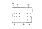
- FIG. 7 is a sectional view (corresponding to a sectional view taken along the line AA) in the radial direction of the rotor of the silencer panel constituting the silencer according to the second embodiment of the present invention.
- FIG. 8 is a side view of a main part of the silencer panel according to the second embodiment. The structure of the silencer panel 41a and the fitting structure between the upstream silencer panel 51 and the downstream silencer panel 52a will be described with reference to FIGS.
- the silencer panel 41a is a metal panel having a structure that can be divided in the direction of air flow.
- the upstream portion is an upstream silencer panel 51 and the downstream portion is a downstream silencer panel 52a.
- the upstream-side silencer panel 51 is a formed box-shaped object having an opening 64 that is open on the side that fits with the downstream-side silencer panel 52a, and the inside is hollow as shown in FIG.
- the downstream-side silencer panel 52a is a box-shaped object having a hollow inside as shown in FIG.
- each of the upstream silencer panel 51 and the downstream silencer panel 52 a is filled with a sound absorbing material 53 made of a porous material having sound absorbing properties. Further, as shown in FIGS. 7 and 8, a plurality of fine holes 62 are formed in the side surface through which air passes in the upstream silencer panel 51. Similarly, a plurality of fine holes 72 are formed in the side surface through which air passes in the downstream silencer panel 52a.
- a protruding portion (fitting portion) 71a having a reduced length in the width direction is formed in the fitting portion of the downstream silencer panel 52a.
- the convex shape portion 71a is fitted to substantially the entire area in the opening 64 of the upstream silencer panel 51, whereby the upstream silencer panel 51 and the downstream silencer panel 52a are connected.
- the side surfaces of the connected upstream silencer panel 51 and downstream silencer panel 52a are substantially flush.
- the fine holes 62 are not drilled in the side surface of the upstream silencer panel 51 where the convex portion 71a is fitted. This is to ensure the strength of the fitting structure between the upstream silencer panel 51 and the downstream silencer panel 52a.
- the above-described configuration of the silencer panel 41a has the same effect as that of the silencer 31 according to the first embodiment, and the fitting portion of the downstream silencer panel 52a is similar to the downstream silencer panel 52 of the first embodiment. Since it is not necessary to provide an opening, the structure can be simplified. For this reason, the manufacturing accuracy of the silencer panel 41a can be improved.
- the gas turbine silencer according to the third embodiment of the present invention will be described focusing on the differences from the gas turbine silencer according to the first embodiment.
- movement of a gas turbine with which the silencer for gas turbines which concerns on Example 3 is provided are the same as that of the gas turbine 1 which concerns on Example 1 shown in FIG.
- the operation of the noise reducing action associated with the air flow caused by the passage of air through the gas turbine silencer according to the third embodiment is the same as that of the gas turbine silencer according to the first embodiment.
- the silencer 31 (see FIG. 1) has a plurality of flat-plate-shaped silencer panels 41b (divided silencer panels), which will be described later, in the duct 42 between the air intake port 15 and the compressor casing 16 and has a plate surface. Along the direction of the air flow from the air intake port 15 toward the compressor casing 16 and along the circumferential direction of the rotor 19, they are arranged in parallel at predetermined intervals.
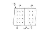
- FIG. 9 is a sectional view (corresponding to a sectional view taken along the line AA) in the radial direction of the rotor of the silencer panel constituting the silencer according to the third embodiment of the present invention.
- FIG. 10 is a side view of an essential part of the silencer panel according to the third embodiment. The structure of the silencer panel 41b and the fitting structure between the upstream silencer panel 51b and the downstream silencer panel 52b will be described with reference to FIGS.
- the silencer panel 41b is a metal panel having a structure that can be divided in the direction of air flow.
- the upstream portion is an upstream silencer panel 51b and the downstream portion is a downstream silencer panel 52b.
- the upstream-side silencer panel 51b is a formed box-shaped object having an opening 64b that is open on the side to be fitted with the downstream-side silencer panel 52b, and has a hollow inside as shown in FIG.
- the downstream silencer panel 52b is a box-shaped object having an opening 74b opened on the side fitted to the upstream silencer panel 51b, and the inside is hollow as shown in FIG.
- each of the cavities of the upstream silencer panel 51b and the downstream silencer panel 52b is filled with a sound absorbing material 53 formed of a porous material having a sound absorbing property.
- a plurality of fine holes 62 are formed in the side surface through which air passes in the upstream silencer panel 51b.
- a plurality of fine holes 72 are formed in the side surface through which air passes in the downstream silencer panel 52b.
- the upstream side silencer panel 51 b has an opening-side portion from a position of a predetermined length L toward the inside from the end of the opening 64 b toward the end of the opening 64 b.
- the fitting portion 63 is formed so that the length in the width direction of the cavity gradually increases.
- the downstream side silencer panel 52b has an opening side portion on both sides of the downstream silencer panel 52b from the position of the length L from the end of the opening 74b to the end of the opening 74b.
- the fitting portion 71b is formed so that the length in the width direction gradually decreases.
- the fitting portion 71b is fitted to substantially the entire area in the opening 64b in which the fitting portion 63 is formed, whereby the upstream silencer panel 51b and the downstream silencer panel 52b are connected.
- the side surfaces of the connected upstream silencer panel 51b and downstream silencer panel 52b are substantially flush.
- fine holes 62 and 72 are formed in the side surface of the upstream silencer panel 51b where the fitting portion 63 is formed and the side surface of the downstream silencer panel 52b where the fitting portion 71b is formed, respectively. It has not been. This is to ensure the strength of the fitting structure between the upstream silencer panel 51b and the downstream silencer panel 52b. Further, as shown in FIGS.
- the cavity corresponding to the side portion where the fine holes 62 and 72 are not drilled that is, the cavity 73 b corresponding to the fitting portion 71 b having the length L
- the sound absorbing material 53 is not filled. This is because even if the sound absorbing material 53 is filled in the cavity corresponding to the side portion where the fine holes are not drilled, it does not contribute to the reduction of noise caused by the air flow.
- the fitting part 71b of the downstream silencer panel 52b is fitted over substantially the entire area within the opening 64b in which the fitting part 63 is formed, whereby the upstream silencer panel 51b. Are connected to the downstream silencer panel 52b.
- the fitting part 71b fits in the substantially whole region in the opening part 64b, the connection intensity
- the side surfaces of the connected upstream silencer panel 51b and downstream silencer panel 52b are substantially flush. With this configuration, there is no step between the side surface of the upstream silencer panel 51b and the side surface of the downstream silencer panel 52b, so that it is possible to suppress the occurrence of air flow turbulence and to generate pressure loss and secondary noise. Can be suppressed.
- the length in the width direction at the end of the opening 74b of the downstream silencer panel 52b is smaller than the length in the width direction at the end of the opening 64b of the upstream silencer panel 51b. Therefore, since the fitting part 71b of the downstream silencer panel 52b can be easily assembled to the fitting part 63 of the upstream silencer panel 51b, the manufacturing workability is improved.
- the hollow portion 73b not filled with the sound absorbing material 53 may be only a portion having a length L where the fitting portion 63 of the upstream silencer panel 51b and the fitting portion 71b of the downstream silencer panel 52b overlap each other. Therefore, since the space that does not need to be filled with the sound absorbing material 53 becomes smaller than the silencer panel 41 of the first embodiment, the silencing performance of the silencer 31 is improved.
- downstream silencer panel 52b has an opening 74b formed on the side where it is fitted with the upstream silencer panel 51b.
- the present invention is not limited to this. That is, the downstream silencer panel 52b only needs to have the fitting portion 71b formed so that the length in the width direction of both side surfaces gradually decreases, and the opening 74b and the hollow portion 73b need not be formed.
- a gas turbine silencer according to a fourth embodiment of the present invention will be described focusing on differences from the gas turbine silencer according to the first embodiment.
- movement of a gas turbine with which the silencer for gas turbines which concerns on Example 4 is provided are the same as that of the gas turbine 1 which concerns on Example 1 shown in FIG.
- the operation of the noise reducing action associated with the air flow caused by the passage of air through the gas turbine silencer according to the fourth embodiment is the same as that of the gas turbine silencer according to the first embodiment.
- the silencer 31 (see FIG. 1) includes a plurality of flat-plate-shaped silencer panels 41c (divided silencer panels), which will be described later, in the duct 42 between the air intake port 15 and the compressor casing 16 and the plate surface thereof. Along the direction of the air flow from the air intake port 15 toward the compressor casing 16 and along the circumferential direction of the rotor 19, they are arranged in parallel at predetermined intervals.
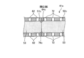
- FIG. 11 is a side view of the main part of the silencer panel constituting the silencer according to the fourth embodiment of the present invention.
- 12 is a configuration diagram of a fitting portion of the silencer panel in the BB cross section of FIG.
- FIG. 13 is a configuration diagram of a contact portion of the silencer panel in the CC section of FIG.
- the structure of the silencer panel 41c and the fitting structure between the upstream silencer panel 51c and the downstream silencer panel 52c will be described with reference to FIGS.
- the silencer panel 41c is a metal panel having a structure that can be divided in the direction of airflow, and an upstream portion is an upstream silencer panel 51c and a downstream portion is a downstream silencer panel 52c.
- the upstream-side silencer panel 51c is a formed box-shaped object having an opening 64c that is open on the side to be fitted with the downstream-side silencer panel 52c, and the inside is hollow as shown in FIGS.
- the downstream-side silencer panel 52c is a box-shaped object having an opening 74c that is open on the side to be fitted with the upstream-side silencer panel 51c, and the inside thereof is hollow as shown in FIGS.
- the cavities of the upstream silencer panel 51c and the downstream silencer panel 52c are filled with a sound absorbing material 53 made of a porous material having sound absorbing properties.
- a plurality of fine holes 62 are formed in the side surface through which air passes in the upstream silencer panel 51c.
- a plurality of fine holes 72 are formed in the side surface through which air passes in the downstream silencer panel 52c.
- a stepped portion (fitting portion) 71c having a small length in the width direction of the silencer panel 41c is provided in the opening side portion of the downstream silencer panel 52c.
- These three step portions 71c are formed in three places.
- the upstream silencer panel 51c and the downstream silencer panel 52c are connected.
- the side surfaces of the connected upstream silencer panel 51c and downstream silencer panel 52c are substantially flush.
- fine holes 62 and 72 are not formed in the side surface of the portion where the stepped portion 71c of the upstream side silencer panel 51c is fitted and the side surface of the stepped portion 71c of the downstream side silencer panel 52c, respectively.
- the cavity corresponding to the side surface portion where the fine holes 62 and 72 are not formed that is, the cavity 73c corresponding to the three step portions 71c of the downstream silencer panel 52c.
- the sound absorbing material 53 is not filled with the sound absorbing material 53. This is because even if the sound absorbing material 53 is filled in the cavity corresponding to the side portion where the fine holes are not drilled, it does not contribute to the reduction of noise caused by the air flow.
- the above-described configuration of the silencer panel 41c has the same effect as that of the silencer 31 according to the first embodiment, and the fitting portion includes only three steps 71c formed on the downstream silencer panel 52c. Therefore, compared with Example 1, since the area
- the configuration of the stepped portion 71c formed in the downstream side silencer panel 52c in the radial direction of the rotor 19 is the same as that of the stepped portion 71 of the first embodiment, but is not limited thereto. In other words, the configuration may be the same as the convex portion 71a of the second embodiment, or the same configuration as the fitting portions 63 and 71b of the third embodiment.
- stepped portions 71c formed in the downstream silencer panel 52c are three in the radial direction of the rotor 19, but the present invention is not limited to this, and the number of stepped portions 71c according to the connection strength to be secured is not limited thereto. It is good also as what forms.
Landscapes
- Engineering & Computer Science (AREA)
- Chemical & Material Sciences (AREA)
- Combustion & Propulsion (AREA)
- Mechanical Engineering (AREA)
- General Engineering & Computer Science (AREA)
- Structures Of Non-Positive Displacement Pumps (AREA)
Abstract
Description
図1は、本発明の実施例1に係るガスタービンの概略構成図である。図1を参照しながら、本実施例に係るガスタービン1の概略構成を説明する。
図2は、実施例1に係るサイレンサの外観斜視図である。図3は、実施例1に係るサイレンサのロータの径方向視の構成図である。図2及び図3を参照しながら、サイレンサ31の構造について説明する。
次に、サイレンサ31を空気が通過することによって、空気の流れに伴う騒音の低減作用の概要について説明する。
サイレンサ31(図1参照)は、空気取込口15と圧縮機車室16との間のダクト42内において、後述する平板状の複数のサイレンサパネル41a(分割型サイレンサパネル)が、その板面が空気取込口15から圧縮機車室16へ向かう空気流の方向に沿うように、かつ、ロータ19の周方向に沿って所定間隔で並設して構成されている。
サイレンサ31(図1参照)は、空気取込口15と圧縮機車室16との間のダクト42内において、後述する平板状の複数のサイレンサパネル41b(分割型サイレンサパネル)が、その板面が空気取込口15から圧縮機車室16へ向かう空気流の方向に沿うように、かつ、ロータ19の周方向に沿って所定間隔で並設して構成されている。
サイレンサ31(図1参照)は、空気取込口15と圧縮機車室16との間のダクト42内において、後述する平板状の複数のサイレンサパネル41c(分割型サイレンサパネル)が、その板面が空気取込口15から圧縮機車室16へ向かう空気流の方向に沿うように、かつ、ロータ19の周方向に沿って所定間隔で並設して構成されている。
11 圧縮機
12 燃焼器
13 タービン部
14 排気室
15 空気取込口
16 圧縮機車室
17 静翼
18 動翼
19 ロータ
20 タービン車室
21 タービン静翼
22 タービン動翼
23 排気ディフューザ
26、27 軸受部
31 サイレンサ
41、41a~41c サイレンサパネル(分割型サイレンサパネル)
42 ダクト
51、51b、51c 上流側サイレンサパネル(上流側のサイレンサパネル)
52、52a~52c 下流側サイレンサパネル(下流側のサイレンサパネル)
53 吸音材
61 ブルノーズ部
62 微細孔
63 嵌合部
64、64b、64c 開口部
71 段差部(嵌合部)
71a 凸形状部(嵌合部)
71b 嵌合部
71c 段差部(嵌合部)
72 微細孔
73、73b、73c 空洞部
74、74b、74c 開口部
L 長さ
Claims (9)
- ガスタービンの空気取込口と圧縮機との間に設置されたガスタービン用サイレンサであって、
前記空気取込口から前記圧縮機に向かう流体の流れ方向に直交する方向に所定間隔で並設された平板状の複数の分割型サイレンサパネルを有し、
該分割型サイレンサパネルは、平板の面積が最も大きい面が、前記流体の流れに沿う向きで配置され、かつ、前記流体の流れ方向において、上流側に配置された上流側のサイレンサパネルと、該上流側のサイレンサパネルの下流側に配置され、該上流側のサイレンサパネルと連結した下流側のサイレンサパネルとを有し、
前記上流側のサイレンサパネル及び前記下流側のサイレンサパネルのうち、一方のサイレンサパネルは、他方のサイレンサパネルと対向する側に開口した開口部が形成され、
前記他方のサイレンサパネルは、前記開口部内に嵌合する嵌合部が形成され、
前記他方のサイレンサパネルの前記嵌合部が前記一方のサイレンサパネルの前記開口部内に嵌合することによって、前記上流側のサイレンサパネルと前記下流側のサイレンサパネルとが連結することを特徴とするガスタービン用サイレンサ。 - 前記分割型サイレンサパネルは、前記一方のサイレンサパネルと前記他方のサイレンサパネルとが連結した場合、前記一方のサイレンサパネル及び前記他方のサイレンサパネルにおける前記流体が接する面が略面一となることを特徴とする請求項1に記載のガスタービン用サイレンサ。
- 前記他方のサイレンサパネルは、前記嵌合部が形成された端面が閉口し、該嵌合部が前記一方のサイレンサパネルに嵌合する向きに凸形状になっていることを特徴とする請求項1又は2に記載のガスタービン用サイレンサ。
- 前記一方のサイレンサパネルは、前記開口部側の端部から内部に向かって所定長さの位置を基点とし、該基点から前記開口部側の端部に向かって、前記分割型サイレンサパネルの並設方向における前記開口部の長さが漸増し、
前記他方のサイレンサパネルは、前記嵌合部側の端部からの前記所定長さの位置を基点とし、前記嵌合部側の端部に向かって、前記並設方向における前記嵌合部の長さが漸減して前記嵌合部が形成されたことを特徴とする請求項1又は2に記載のガスタービン用サイレンサ。 - 前記他方のサイレンサパネルは、前記嵌合部が前記一方のサイレンサパネルの前記開口部内の略全域に嵌合することを特徴とする請求項1~4のいずれか一項に記載のガスタービン用サイレンサ。
- 前記他方のサイレンサパネルは、前記嵌合部が前記一方のサイレンサパネルの前記開口部内の一部において嵌合することを特徴とする請求項1~4のいずれか一項に記載のガスタービン用サイレンサ。
- 前記他方のサイレンサパネルは、前記嵌合部が複数形成されたことを特徴とする請求項6に記載のガスタービン用サイレンサ。
- 前記分割型サイレンサパネルは、内部が空洞の箱形状であり、前記流体が接する側面に複数の微細孔が形成され、前記空洞に吸音材が充填されたことを特徴とする請求項1~7のいずれか一項に記載のガスタービン用サイレンサ。
- 前記空気取込口から取り込んだ空気を圧縮する前記圧縮機と、
該圧縮機によって圧縮された圧縮空気に対して燃料を供給し、点火及び燃焼させて燃焼ガスを生成する燃焼器と、
前記燃焼ガスによってロータに回転動力を発生させるタービン部と、
該タービン部を通過した前記燃焼ガスを外部に排出する排気室と、
前記空気取込口と前記圧縮機との間に配置された請求項1~8のいずれか一項に記載のガスタービン用サイレンサと、
を備えたことを特徴とするガスタービン。
Priority Applications (4)
| Application Number | Priority Date | Filing Date | Title |
|---|---|---|---|
| DE112014001467.2T DE112014001467B4 (de) | 2013-03-15 | 2014-02-10 | Gasturbinenschalldämpfer und mit selbigem versehene Gasturbine |
| CN201480011339.XA CN105026729B (zh) | 2013-03-15 | 2014-02-10 | 燃气轮机用消音器、及装备了该消音器的燃气轮机 |
| US14/771,357 US10240535B2 (en) | 2013-03-15 | 2014-02-10 | Gas turbine silencer, and gas turbine provided with same |
| KR1020157023464A KR101723323B1 (ko) | 2013-03-15 | 2014-02-10 | 가스 터빈용 소음기 및 이 소음기를 구비한 가스 터빈 |
Applications Claiming Priority (2)
| Application Number | Priority Date | Filing Date | Title |
|---|---|---|---|
| JP2013053693A JP6057790B2 (ja) | 2013-03-15 | 2013-03-15 | ガスタービン用サイレンサ、及びそれを備えたガスタービン |
| JP2013-053693 | 2013-03-15 |
Publications (1)
| Publication Number | Publication Date |
|---|---|
| WO2014141791A1 true WO2014141791A1 (ja) | 2014-09-18 |
Family
ID=51536467
Family Applications (1)
| Application Number | Title | Priority Date | Filing Date |
|---|---|---|---|
| PCT/JP2014/053036 Ceased WO2014141791A1 (ja) | 2013-03-15 | 2014-02-10 | ガスタービン用サイレンサ、及びそれを備えたガスタービン |
Country Status (6)
| Country | Link |
|---|---|
| US (1) | US10240535B2 (ja) |
| JP (1) | JP6057790B2 (ja) |
| KR (1) | KR101723323B1 (ja) |
| CN (1) | CN105026729B (ja) |
| DE (1) | DE112014001467B4 (ja) |
| WO (1) | WO2014141791A1 (ja) |
Cited By (28)
| Publication number | Priority date | Publication date | Assignee | Title |
|---|---|---|---|---|
| CN105041473A (zh) * | 2015-08-21 | 2015-11-11 | 成都博世德能源科技股份有限公司 | 一种用于燃气轮机的三级高效消声空气过滤系统 |
| CN105089796A (zh) * | 2015-08-26 | 2015-11-25 | 成都博世德能源科技股份有限公司 | 用于燃气轮机的转叶式高效降噪空气过滤装置 |
| CN105089810A (zh) * | 2015-08-21 | 2015-11-25 | 成都博世德能源科技股份有限公司 | 燃气轮机的三级高效消声空气过滤装置 |
| CN105089811A (zh) * | 2015-08-26 | 2015-11-25 | 成都博世德能源科技股份有限公司 | 一种用于燃气轮机的三级高效降噪空气过滤系统 |
| CN105089791A (zh) * | 2015-08-21 | 2015-11-25 | 成都博世德能源科技股份有限公司 | 转叶式高效消声空气过滤装置 |
| CN105089814A (zh) * | 2015-08-26 | 2015-11-25 | 成都博世德能源科技股份有限公司 | 一种用于燃气轮机循环利用的高效降噪空气过滤装置 |
| CN105089813A (zh) * | 2015-08-26 | 2015-11-25 | 成都博世德能源科技股份有限公司 | 一种用于燃气轮机的转叶式高效降噪空气过滤装置 |
| CN105089801A (zh) * | 2015-08-26 | 2015-11-25 | 成都博世德能源科技股份有限公司 | 一种集成式多级高效降噪空气过滤系统 |
| CN105089792A (zh) * | 2015-08-21 | 2015-11-25 | 成都博世德能源科技股份有限公司 | 一种高效循环利用的消声空气过滤装置 |
| CN105089806A (zh) * | 2015-08-21 | 2015-11-25 | 成都博世德能源科技股份有限公司 | 一种高效消声的三级空气过滤系统 |
| CN105089789A (zh) * | 2015-08-21 | 2015-11-25 | 成都博世德能源科技股份有限公司 | 用于燃气轮机空气净化的多级集成式高效消声过滤系统 |
| CN105089795A (zh) * | 2015-08-21 | 2015-11-25 | 成都博世德能源科技股份有限公司 | 一种集成式多级高效消声空气过滤系统 |
| CN105089809A (zh) * | 2015-08-21 | 2015-11-25 | 成都博世德能源科技股份有限公司 | 一种用于空气净化高效消声的进气装置 |
| CN105089805A (zh) * | 2015-08-21 | 2015-11-25 | 成都博世德能源科技股份有限公司 | 一种转叶式高效消声空气过滤装置 |
| CN105080230A (zh) * | 2015-08-21 | 2015-11-25 | 成都博世德能源科技股份有限公司 | 一种用于空气净化高效消声的多级过滤集成系统 |
| CN105089787A (zh) * | 2015-08-21 | 2015-11-25 | 成都博世德能源科技股份有限公司 | 一种用于燃气轮机的转叶式高效消声空气过滤装置 |
| CN105089803A (zh) * | 2015-08-21 | 2015-11-25 | 成都博世德能源科技股份有限公司 | 高效消声的三级空气过滤系统 |
| CN105089793A (zh) * | 2015-08-21 | 2015-11-25 | 成都博世德能源科技股份有限公司 | 一种用于燃气轮机的高效消声空气过滤筒 |
| CN105089808A (zh) * | 2015-08-21 | 2015-11-25 | 成都博世德能源科技股份有限公司 | 一种用于燃气轮机高效消声的进气装置 |
| CN105089807A (zh) * | 2015-08-21 | 2015-11-25 | 成都博世德能源科技股份有限公司 | 一种用于燃气轮机循环利用的高效消声空气过滤装置 |
| CN105089804A (zh) * | 2015-08-21 | 2015-11-25 | 成都博世德能源科技股份有限公司 | 一种用于燃气轮机的高效消声筒式空气过滤器 |
| CN105089794A (zh) * | 2015-08-21 | 2015-11-25 | 成都博世德能源科技股份有限公司 | 一种用于燃气轮机的高效消声进气装置 |
| CN105089788A (zh) * | 2015-08-21 | 2015-11-25 | 成都博世德能源科技股份有限公司 | 一种高效消声的转叶式粗效过滤装置 |
| CN105114182A (zh) * | 2015-08-21 | 2015-12-02 | 成都博世德能源科技股份有限公司 | 一种高效节能转叶式消声空气过滤装置 |
| CN105114183A (zh) * | 2015-08-26 | 2015-12-02 | 成都博世德能源科技股份有限公司 | 一种用于空气净化的多级高效降噪过滤集成系统 |
| CN105134384A (zh) * | 2015-08-26 | 2015-12-09 | 成都博世德能源科技股份有限公司 | 用于燃气轮机空气净化的多级集成式高效降噪过滤系统 |
| EP3144489A1 (en) * | 2015-09-16 | 2017-03-22 | General Electric Company | Silencer panel having sections and related silencer duct |
| JP2018044548A (ja) * | 2016-09-15 | 2018-03-22 | ゼネラル・エレクトリック・カンパニイ | モジュール化されたサイレンサバッフルを取り付けおよび取り外すための方法 |
Families Citing this family (9)
| Publication number | Priority date | Publication date | Assignee | Title |
|---|---|---|---|---|
| US20170292456A1 (en) * | 2016-04-12 | 2017-10-12 | General Electric Company | Integrated gas turbine inlet silencer and bleed heat system |
| EP3474661A4 (en) * | 2016-06-28 | 2020-07-29 | Egg Waves Ltd. | SYSTEM, APPARATUS AND METHOD FOR NON-INVASIVE DETECTION OF THE FERTILITY OF A AVIAN EGG |
| US10119469B2 (en) * | 2016-09-15 | 2018-11-06 | General Electric Company | Method and apparatus for modularized inlet silencer baffles |
| CN108278157B (zh) * | 2017-01-06 | 2022-08-02 | 通用电气公司 | 用于改进的入口消音挡板的系统和方法 |
| CN108278158B (zh) * | 2017-01-06 | 2022-05-13 | 通用电气公司 | 用于改进的入口消音挡板的系统和方法 |
| JP6929144B2 (ja) * | 2017-06-27 | 2021-09-01 | キヤノン株式会社 | 情報処理装置、プログラム、インストーラ及び制御方法 |
| US11415032B2 (en) | 2019-12-23 | 2022-08-16 | Rheem Manufacturing Company | Noise muffler for an air moving device |
| US11713663B2 (en) | 2020-11-06 | 2023-08-01 | Yantai Jereh Petroleum Equipment & Technologies Co., Ltd. | Heat radiator and turbo fracturing unit comprising the same |
| CN112228208A (zh) * | 2020-11-06 | 2021-01-15 | 烟台杰瑞石油装备技术有限公司 | 散热装置和具有散热装置的涡轮压裂设备 |
Citations (4)
| Publication number | Priority date | Publication date | Assignee | Title |
|---|---|---|---|---|
| JPS5947307U (ja) * | 1982-09-21 | 1984-03-29 | 三菱重工業株式会社 | 消音器 |
| JPS6066811U (ja) * | 1983-10-14 | 1985-05-11 | 三菱重工業株式会社 | 消音器 |
| JPH07224685A (ja) * | 1994-02-16 | 1995-08-22 | Toshiba Corp | ガスタービン用サイレンサ |
| JP2004028107A (ja) * | 2003-07-07 | 2004-01-29 | Toshiba Corp | ガスタービン用サイレンサ |
Family Cites Families (10)
| Publication number | Priority date | Publication date | Assignee | Title |
|---|---|---|---|---|
| JPS5947307A (ja) | 1982-09-09 | 1984-03-17 | Goto Gokin Kk | 溶鉱炉における羽口構造体 |
| JPS6066811A (ja) * | 1983-09-24 | 1985-04-17 | Sharp Corp | 化合物半導体装置の製造方法 |
| US6260658B1 (en) * | 1998-10-23 | 2001-07-17 | Donaldson Company, Inc. | Silencer for a gas turbine |
| JP2003097292A (ja) * | 2001-09-21 | 2003-04-03 | Mitsubishi Heavy Ind Ltd | 吸気消音器 |
| US6851514B2 (en) | 2002-04-15 | 2005-02-08 | Air Handling Engineering Ltd. | Outlet silencer and heat recovery structures for gas turbine |
| DE10254824A1 (de) | 2002-11-25 | 2004-06-09 | Alstom Technology Ltd | Ansaugschalldämpfer für Gasturbinen |
| CN2622404Y (zh) * | 2003-05-23 | 2004-06-30 | 中国南方航空动力机械公司 | 燃气轮机进气装置 |
| WO2009034629A1 (ja) * | 2007-09-13 | 2009-03-19 | Alphatech Co., Ltd. | ガスタービン吸気サイレンサ |
| US8459407B2 (en) | 2008-10-01 | 2013-06-11 | General Electric Company | Sound attenuation systems and methods |
| US8469588B2 (en) * | 2010-05-03 | 2013-06-25 | General Electric Company | System and method for compressor inlet temperature measurement |
-
2013
- 2013-03-15 JP JP2013053693A patent/JP6057790B2/ja active Active
-
2014
- 2014-02-10 US US14/771,357 patent/US10240535B2/en active Active
- 2014-02-10 CN CN201480011339.XA patent/CN105026729B/zh active Active
- 2014-02-10 WO PCT/JP2014/053036 patent/WO2014141791A1/ja not_active Ceased
- 2014-02-10 DE DE112014001467.2T patent/DE112014001467B4/de active Active
- 2014-02-10 KR KR1020157023464A patent/KR101723323B1/ko active Active
Patent Citations (4)
| Publication number | Priority date | Publication date | Assignee | Title |
|---|---|---|---|---|
| JPS5947307U (ja) * | 1982-09-21 | 1984-03-29 | 三菱重工業株式会社 | 消音器 |
| JPS6066811U (ja) * | 1983-10-14 | 1985-05-11 | 三菱重工業株式会社 | 消音器 |
| JPH07224685A (ja) * | 1994-02-16 | 1995-08-22 | Toshiba Corp | ガスタービン用サイレンサ |
| JP2004028107A (ja) * | 2003-07-07 | 2004-01-29 | Toshiba Corp | ガスタービン用サイレンサ |
Cited By (31)
| Publication number | Priority date | Publication date | Assignee | Title |
|---|---|---|---|---|
| CN105089794A (zh) * | 2015-08-21 | 2015-11-25 | 成都博世德能源科技股份有限公司 | 一种用于燃气轮机的高效消声进气装置 |
| CN105089803A (zh) * | 2015-08-21 | 2015-11-25 | 成都博世德能源科技股份有限公司 | 高效消声的三级空气过滤系统 |
| CN105089810A (zh) * | 2015-08-21 | 2015-11-25 | 成都博世德能源科技股份有限公司 | 燃气轮机的三级高效消声空气过滤装置 |
| CN105114182A (zh) * | 2015-08-21 | 2015-12-02 | 成都博世德能源科技股份有限公司 | 一种高效节能转叶式消声空气过滤装置 |
| CN105089791A (zh) * | 2015-08-21 | 2015-11-25 | 成都博世德能源科技股份有限公司 | 转叶式高效消声空气过滤装置 |
| CN105089788A (zh) * | 2015-08-21 | 2015-11-25 | 成都博世德能源科技股份有限公司 | 一种高效消声的转叶式粗效过滤装置 |
| CN105041473A (zh) * | 2015-08-21 | 2015-11-11 | 成都博世德能源科技股份有限公司 | 一种用于燃气轮机的三级高效消声空气过滤系统 |
| CN105089804A (zh) * | 2015-08-21 | 2015-11-25 | 成都博世德能源科技股份有限公司 | 一种用于燃气轮机的高效消声筒式空气过滤器 |
| CN105089792A (zh) * | 2015-08-21 | 2015-11-25 | 成都博世德能源科技股份有限公司 | 一种高效循环利用的消声空气过滤装置 |
| CN105089806A (zh) * | 2015-08-21 | 2015-11-25 | 成都博世德能源科技股份有限公司 | 一种高效消声的三级空气过滤系统 |
| CN105089789A (zh) * | 2015-08-21 | 2015-11-25 | 成都博世德能源科技股份有限公司 | 用于燃气轮机空气净化的多级集成式高效消声过滤系统 |
| CN105089795A (zh) * | 2015-08-21 | 2015-11-25 | 成都博世德能源科技股份有限公司 | 一种集成式多级高效消声空气过滤系统 |
| CN105089809A (zh) * | 2015-08-21 | 2015-11-25 | 成都博世德能源科技股份有限公司 | 一种用于空气净化高效消声的进气装置 |
| CN105089805A (zh) * | 2015-08-21 | 2015-11-25 | 成都博世德能源科技股份有限公司 | 一种转叶式高效消声空气过滤装置 |
| CN105089807A (zh) * | 2015-08-21 | 2015-11-25 | 成都博世德能源科技股份有限公司 | 一种用于燃气轮机循环利用的高效消声空气过滤装置 |
| CN105080230A (zh) * | 2015-08-21 | 2015-11-25 | 成都博世德能源科技股份有限公司 | 一种用于空气净化高效消声的多级过滤集成系统 |
| CN105089808A (zh) * | 2015-08-21 | 2015-11-25 | 成都博世德能源科技股份有限公司 | 一种用于燃气轮机高效消声的进气装置 |
| CN105089793A (zh) * | 2015-08-21 | 2015-11-25 | 成都博世德能源科技股份有限公司 | 一种用于燃气轮机的高效消声空气过滤筒 |
| CN105089787A (zh) * | 2015-08-21 | 2015-11-25 | 成都博世德能源科技股份有限公司 | 一种用于燃气轮机的转叶式高效消声空气过滤装置 |
| CN105089796A (zh) * | 2015-08-26 | 2015-11-25 | 成都博世德能源科技股份有限公司 | 用于燃气轮机的转叶式高效降噪空气过滤装置 |
| CN105089801A (zh) * | 2015-08-26 | 2015-11-25 | 成都博世德能源科技股份有限公司 | 一种集成式多级高效降噪空气过滤系统 |
| CN105089813A (zh) * | 2015-08-26 | 2015-11-25 | 成都博世德能源科技股份有限公司 | 一种用于燃气轮机的转叶式高效降噪空气过滤装置 |
| CN105089814A (zh) * | 2015-08-26 | 2015-11-25 | 成都博世德能源科技股份有限公司 | 一种用于燃气轮机循环利用的高效降噪空气过滤装置 |
| CN105089811A (zh) * | 2015-08-26 | 2015-11-25 | 成都博世德能源科技股份有限公司 | 一种用于燃气轮机的三级高效降噪空气过滤系统 |
| CN105114183A (zh) * | 2015-08-26 | 2015-12-02 | 成都博世德能源科技股份有限公司 | 一种用于空气净化的多级高效降噪过滤集成系统 |
| CN105134384A (zh) * | 2015-08-26 | 2015-12-09 | 成都博世德能源科技股份有限公司 | 用于燃气轮机空气净化的多级集成式高效降噪过滤系统 |
| EP3144489A1 (en) * | 2015-09-16 | 2017-03-22 | General Electric Company | Silencer panel having sections and related silencer duct |
| CN106545417A (zh) * | 2015-09-16 | 2017-03-29 | 通用电气公司 | 消音面板区段以及相关消音管道 |
| JP2017062465A (ja) * | 2015-09-16 | 2017-03-30 | ゼネラル・エレクトリック・カンパニイ | セクションを有するサイレンサパネル、および関連するサイレンサダクト |
| JP2018044548A (ja) * | 2016-09-15 | 2018-03-22 | ゼネラル・エレクトリック・カンパニイ | モジュール化されたサイレンサバッフルを取り付けおよび取り外すための方法 |
| JP7123533B2 (ja) | 2016-09-15 | 2022-08-23 | ゼネラル・エレクトリック・カンパニイ | モジュール化されたサイレンサバッフルを取り付けおよび取り外すための方法 |
Also Published As
| Publication number | Publication date |
|---|---|
| US10240535B2 (en) | 2019-03-26 |
| DE112014001467B4 (de) | 2022-10-06 |
| KR101723323B1 (ko) | 2017-04-04 |
| JP6057790B2 (ja) | 2017-01-11 |
| CN105026729B (zh) | 2018-01-09 |
| JP2014177921A (ja) | 2014-09-25 |
| DE112014001467T5 (de) | 2015-11-26 |
| US20160010557A1 (en) | 2016-01-14 |
| CN105026729A (zh) | 2015-11-04 |
| KR20150108426A (ko) | 2015-09-25 |
Similar Documents
| Publication | Publication Date | Title |
|---|---|---|
| JP6057790B2 (ja) | ガスタービン用サイレンサ、及びそれを備えたガスタービン | |
| US8733496B2 (en) | Acoustic damper, combustor, and gas turbine | |
| US8839624B2 (en) | Combustion device of a gas turbine including a plurality of passages and chambers defining helmholtz resonators | |
| CN102575526B (zh) | 密封元件、燃气涡轮机喷嘴设备和燃气涡轮机 | |
| US9194239B2 (en) | Turbine rotor blade and turbo machine | |
| EP2192290A1 (en) | Damping device and gas turbine combustor | |
| CN103775213B (zh) | 燃烧器过渡件 | |
| CA2673001A1 (en) | Jet flow discharge nozzle and jet engine | |
| CN107250491A (zh) | 衰减装置、燃烧器以及燃气轮机 | |
| JP6173811B2 (ja) | シール装置およびガスタービン | |
| JP2017172374A (ja) | 軸流圧縮機及び軸流圧縮機を備えたガスタービン | |
| JP2018135803A (ja) | 回転機械の翼のダンパ装置及び回転機械 | |
| JP2010276010A (ja) | タービン翼、タービン翼の製造方法、及び、ガスタービン | |
| CN114450467A (zh) | 支柱罩、排气机室以及燃气轮机 | |
| US10415391B2 (en) | Rotor and gas turbine engine including a rotor | |
| EP2960432A1 (en) | Rotor and gas turbine engine including a rotor | |
| JP6871377B2 (ja) | ガスタービンの1段静翼、ガスタービン、ガスタービンの静翼ユニット及び燃焼器アセンブリ | |
| KR102059327B1 (ko) | 연소기용 통, 연소기 및 가스 터빈 | |
| JP7171484B2 (ja) | 吸音装置及びガスタービン | |
| KR101891449B1 (ko) | 가스 터빈 | |
| CN117015659A (zh) | 燃气轮机用燃烧器、燃气轮机及燃气轮机的组装方法 | |
| JP6578225B2 (ja) | 吸音スプリッタ、サイレンサ、ガスタービン用煙突、および、ガスタービン | |
| JP7599361B2 (ja) | タービン動翼及びタービン | |
| JP7661528B2 (ja) | 配管の支持構造体、吸気ダクト、及びガスタービン | |
| WO2018037456A1 (ja) | 吸音ライナ |
Legal Events
| Date | Code | Title | Description |
|---|---|---|---|
| WWE | Wipo information: entry into national phase |
Ref document number: 201480011339.X Country of ref document: CN |
|
| 121 | Ep: the epo has been informed by wipo that ep was designated in this application |
Ref document number: 14764338 Country of ref document: EP Kind code of ref document: A1 |
|
| ENP | Entry into the national phase |
Ref document number: 20157023464 Country of ref document: KR Kind code of ref document: A |
|
| WWE | Wipo information: entry into national phase |
Ref document number: 14771357 Country of ref document: US |
|
| WWE | Wipo information: entry into national phase |
Ref document number: 112014001467 Country of ref document: DE Ref document number: 1120140014672 Country of ref document: DE |
|
| 122 | Ep: pct application non-entry in european phase |
Ref document number: 14764338 Country of ref document: EP Kind code of ref document: A1 |