WO2014136551A1 - バグフィルター用空気増幅装置および該バグフィルター用空気増幅装置を用いたバグフィルター用空気増幅システム - Google Patents
バグフィルター用空気増幅装置および該バグフィルター用空気増幅装置を用いたバグフィルター用空気増幅システム Download PDFInfo
- Publication number
- WO2014136551A1 WO2014136551A1 PCT/JP2014/053505 JP2014053505W WO2014136551A1 WO 2014136551 A1 WO2014136551 A1 WO 2014136551A1 JP 2014053505 W JP2014053505 W JP 2014053505W WO 2014136551 A1 WO2014136551 A1 WO 2014136551A1
- Authority
- WO
- WIPO (PCT)
- Prior art keywords
- air
- compressed air
- bag filter
- compressed
- amplifying device
- Prior art date
- Legal status (The legal status is an assumption and is not a legal conclusion. Google has not performed a legal analysis and makes no representation as to the accuracy of the status listed.)
- Ceased
Links
Images




Classifications
-
- B—PERFORMING OPERATIONS; TRANSPORTING
- B01—PHYSICAL OR CHEMICAL PROCESSES OR APPARATUS IN GENERAL
- B01D—SEPARATION
- B01D46/00—Filters or filtering processes specially modified for separating dispersed particles from gases or vapours
- B01D46/02—Particle separators, e.g. dust precipitators, having hollow filters made of flexible material
- B01D46/04—Cleaning filters
-
- B—PERFORMING OPERATIONS; TRANSPORTING
- B01—PHYSICAL OR CHEMICAL PROCESSES OR APPARATUS IN GENERAL
- B01D—SEPARATION
- B01D46/00—Filters or filtering processes specially modified for separating dispersed particles from gases or vapours
- B01D46/66—Regeneration of the filtering material or filter elements inside the filter
- B01D46/70—Regeneration of the filtering material or filter elements inside the filter by acting counter-currently on the filtering surface, e.g. by flushing on the non-cake side of the filter
- B01D46/71—Regeneration of the filtering material or filter elements inside the filter by acting counter-currently on the filtering surface, e.g. by flushing on the non-cake side of the filter with pressurised gas, e.g. pulsed air
Definitions
- the present invention relates to an air amplifier for a bag filter. More specifically, the present invention relates to a bag filter air amplifying device used for bag filter backwashing and a bag filter air amplifying system using the bag filter air amplifying device.
- bag filters filter cloth type dust collectors
- a bag filter is one of filtration dust collectors, and is a device that uses a woven fabric or a nonwoven fabric as a filter medium and makes it cylindrical to remove dust or collect powder.
- Patent Document 1 includes a cleaning circuit that selectively connects a dust-containing air chamber and a purified air chamber.
- the circuit includes a toxic gas removing member, a heater, and a hot air circulation fan, and purified air.
- a filter cloth type dust collector that allows an operator to enter and allows the filter cloth to be taken out easily.
- the filter cloth type dust collector of Patent Document 1 includes a reverse injection pipe that feeds compressed air (reference numeral 12 in FIG. 1 of Patent Document 1) and a nozzle that injects compressed air (reference numeral 13 in FIG. 1 of Patent Document 1). It is designed so that backwashing can be performed.
- bag filters have been backwashed using an air amplifier having a Coanda effect. Since air for backwashing is jetted from the air amplifying device having the Coanda effect almost parallel to the side of the filter, dust and powder adhering to the filter can be removed without damaging the side of the filter. Can do.
- Patent Document 2 discloses a Coanda injector in which an inlet for pressurized air and an inlet for external air are arranged on the same plane in order to reduce pressure loss due to a change in the path of pressurized air. ing.
- Patent Document 3 a pipe for supplying compressed air is divided into two branch pipes, and an air amplifier is connected to the upper part of the branch pipe, and the peripheral equipment is obstructed by the air pressure amplified from the air amplifier.
- a compressed air injection device using an air amplifier that can uniformly supply a larger amount of ambient air to a bag filter at a higher speed so as to exhibit a high dust removal effect.
- the compressed air is sent to a compressed air introduction portion (reference numeral (1) in FIG. 3 of Patent Document 3).
- the supplied compressed air is injected from the compressed air injection hole to the air amplifying unit (reference (3) in FIG. 3)
- the Coanda effect is generated. Due to the generated Coanda effect, external air is attracted to the air amplifying unit (reference numeral 4 in FIG. 3 of Patent Document 3), and the air is amplified.
- a spacer or the like is disposed in the compressed air injection hole portion to secure the compressed air injection hole. That is, the lower body (reference numeral 222 in FIG. 3 of Patent Document 3) and the upper body (reference numeral 221 in FIG. 3 of Patent Document 3 and reference numeral 10 in FIG. 5 of Patent Document 2) following the air amplifying unit are compressed air.
- a compressed air introduction part reference numeral 5 in FIG. 5 in Patent Document 2) without a gap between the injection holes is formed, and then a spacer (reference numeral 16 in FIG. 5 in Patent Document 2) is disposed in the compressed air injection hole portion. Thus, a gap between the compressed air injection holes was secured.
- a spacer (reference numeral 16 in FIG. 5 in Patent Document 2) is disposed in the compressed air injection hole portion to secure a gap between the compressed air injection holes.
- a gap is forcibly formed by the spacer between the upper body and the lower body that are in close contact with each other, a force to return to the close state is generated and the spacer is disposed.
- the upper body of the part that does not exist falls, and there is a difference in the size of the gap between the spacer part and the part without the spacer.
- the present invention has a main object to provide an air amplifying device excellent in compressed air injection ability from a compressed air injection hole and suitable for backwashing a bag filter. .
- the inventor of the present application diligently studied about a specific configuration for securing the gap of the compressed air injection hole. As a result, the idea was changed from the conventional structure, and the compressed air injection hole Focusing on the structure other than the part, the present invention has been completed.
- an air amplifier used for backwashing a bag filter An external air inlet for attracting external air, an amplified air outlet for discharging amplified air, and a cylindrical side wall provided from the external air inlet to the amplified air outlet
- An air amplification unit Compressed air introduction port for introducing compressed air, compressed air injection hole for injecting compressed air to the air amplifying unit, and a curve for guiding the compressed air introduced from the compressed air introduction port to the compressed air injection hole
- a compressed air introduction part provided with a compressed air guide wall, Comprising at least The compressed air introduction part is A first member including the compressed air guide wall; A second member connected to the air amplification unit; A caulking portion to which the first member and the second member are joined; A shim member that is sandwiched between the first member and the second member and adjusts the width of the compressed air injection hole;
- An air amplifying device for a bag filter comprising: As a specific form of the shim member of the air amplifier for a bag filter
- a shield plate may be provided inside the compressed air introduction portion of the bag filter air amplifying device according to the present invention so as to partially shield the flow direction of the compressed air inside the compressed air introduction portion.
- the shielding plate can be provided continuously with the shim member.
- the said shielding board can be provided in the flow direction side immediately after introduction
- the bag filter air amplifying device according to the present invention described above is suitable as an air amplifying system used for backwashing a bag filter by adding a compressed air introduction pipe for introducing compressed air to the compressed air introducing portion of the air amplifying device. Can be used.
- the compressed air injection hole has a desired gap and the gap is kept constant, so that the compressed air from the compressed air injection hole is larger than the conventional air amplifying device. High injection capacity. As a result, it is possible to efficiently generate the Coanda effect and improve the air amplification efficiency.
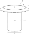
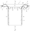
- FIG. 1 is a schematic perspective view schematically showing a first embodiment of a bag filter air amplifying device 1 according to the present invention. It is the cross-sectional schematic diagram which looked at 1st Embodiment of the air amplifier for bag filters 1 concerning this invention from the side surface. It is the cross-sectional schematic diagram which looked at 2nd Embodiment of the air amplifier for bag filters 1 concerning this invention from the side surface. It is the plane schematic diagram which looked at 1st Embodiment of the air amplifier for bag filters 1 concerning the present invention from the upper part side. It is the plane schematic diagram which looked at 3rd Embodiment of the air amplifier 1 for bag filters which concerns on this invention from the upper side.
- FIG. 1 is a schematic perspective view schematically showing a first embodiment of an air amplifying device 1 for a bag filter according to the present invention.
- FIG. 2 is a schematic cross-sectional view of the first embodiment of the bag filter air amplifying device 1 according to the present invention as viewed from the side.
- the bag filter air amplifying device 1 is roughly divided into at least an air amplifying unit 11 and a compressed air introducing unit 12.
- the air amplification unit 11 includes an external air induction port 111, an amplification air discharge port 112, and a side wall 113
- the compressed air introduction unit 12 includes a compressed air introduction port 121, a compressed air injection hole 122, A compressed air guide wall 123 and a shielding plate 124 as necessary are provided.
- the structural features of each unit and the compressed air introduction unit 12 will be described in detail.
- Air amplifier 11 The air amplifying unit 11 is a part that amplifies air using the Coanda effect by the compressed air injected from the compressed air introducing unit 12 described later.
- the external air inlet 111 is a part that attracts external air due to the Coanda effect.
- the flow of external air to be attracted shown in Figure 2 reference numeral F 3.
- the opening area and the opening shape of the external air inlet 111 are not particularly limited as long as the effects of the present invention are not impaired, and can be freely designed according to the size of the filter cloth used for the target bag filter. As an example, for example, when the diameter of the filter cloth of the bag filter is about 150 mm, the external air inlet 111 can be designed with an inner diameter of 70 to 80 mm.
- the amplified air discharge port 112 is a part that discharges the amplified air toward the bag filter.
- the flow of amplified air is discharged, shown in Figure 2 reference numeral F 4.
- the opening area and the opening shape of the amplified air discharge port 112 are not particularly limited as long as the effects of the present invention are not impaired, and can be freely designed according to the size of the filter cloth used for the target bag filter. For example, when the diameter of the bag cloth of the bag filter is about 150 mm, the amplified air discharge port 112 can be designed with an inner diameter of 70 to 80 mm.
- the external air inlet 111 and the amplified air outlet 112 are designed to have the same opening area and shape (see, for example, FIG. 3 of Patent Document 3).
- the external air inlet 111 and the amplified air outlet 112 can be designed to have the same opening area and opening shape as in the prior art.
- the cross-sectional area of the amplified air discharge port 112 As a method of designing the cross-sectional area of the amplified air discharge port 112 to be wider than the cross-sectional area of the external air induction port 111, there is a method of expanding a predetermined portion of the side wall 113 described later to the outside. At this time, it is preferable that the side wall 113 is widened outwardly at a portion where the Coanda effect by the compressed air injected from the compressed air injection hole 122 is at least maintained (see symbol W in FIG. 3). At a part where the Coanda effect is at least sustained, the air amplification efficiency can be reliably improved by expanding the side wall 113 outward.
- the side wall 113 is provided from the external air induction port 111 to the amplification air discharge port 112, and external air attracted from the external air induction port 111 and compressed air injected from a compressed air injection hole 122 described later. In order to guide to the amplified air discharge port 112, it has a cylindrical shape. Specific aspects such as the length of the side wall 113 are not particularly limited as long as the effects of the present invention are not impaired, and can be freely designed in accordance with a target bag filter or the like.
- the compressed air introduction part 12 is a part for introducing the compressed air sent from the compressed air introduction pipe 2 to be described later into the bag filter air amplifying apparatus 1 according to the present invention.
- the compressed air introducing portion 12 of the air amplifying device 1 comprises a first member A, a second member B, and a shim member D. And The first member A and the second member B are joined at the caulking portion C. And the shim member D is provided in the state clamped by the 1st member A and the 2nd member B in this caulking part C.
- a spacer (not shown) or the like is disposed in the compressed air injection hole 122 to secure a gap between the compressed air injection holes 122.
- the gap is forcibly formed by the spacer between the first member A and the second member B that are originally in close contact with each other, the first member A and the second member B are in a close contact state.
- a force to return to the first portion A is generated, the first member A in a portion where the spacer is not disposed falls, and there is a difference in the size of the gap in the spacer portion and the gap in the portion without the spacer.
- the flow of compressed air is hindered by the spacer.
- the idea is changed from the structure of the conventional air amplifying device, and the compressed air is interposed between the first member A and the second member B in the caulking portion C.
- the shim member D for adjusting the width of the injection hole 122, the conventional problem was successfully solved. That is, since the shim member D is disposed between the first member A and the second member B in the caulking portion C, a force that causes the first member A and the second member B to return to a close state is generated. do not do. Therefore, the gap between the compressed air injection holes 122 can be kept constant at a desired size.
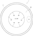
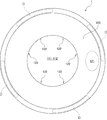
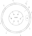
- FIG. 4 to 6 are schematic plan views of the bag filter air amplifying device 1 according to the present invention as viewed from the upper side.
- the form of the shim member D used in the air amplifying device 1 according to the present invention is not particularly limited as long as the effects of the present invention are not impaired.
- it may be ring-shaped as in the first embodiment shown in FIG. 4, or a plurality of arc-shaped shim members D as in the third embodiment shown in FIG. 5 or the fourth embodiment shown in FIG. Can also be provided.
- the compressed air introduction port 121 is a part for introducing the compressed air sent from the compressed air introduction pipe 2 described later into the compressed air introduction unit 12.
- the flow of compressed air introduced is shown in Figure 2 reference numeral F 1.
- the specific aspects such as the opening area and the opening shape of the compressed air inlet 121 are not particularly limited as long as the effects of the present invention are not impaired, and can be freely selected according to the target bag filter or the form of the compressed air inlet pipe 2 to be connected. Can be designed to
- (C) Compressed air injection hole 122 The compressed air injection hole 122 is a part for injecting the compressed air introduced from the compressed air introduction port 121 to the air amplifying unit 11.
- the flow of compressed air injected shown in Figure 2 reference numeral F 2.
- the gaps of the compressed air injection holes 122 are exaggerated as compared with an actual device.
- the injection angle of the compressed air from the compressed air injection hole 122 to the air amplifying unit 11 is not particularly limited. It is preferable to inject at an angle smaller than 90 °. As described above, the compressed air from the compressed air injection hole 122 to the air amplifying unit 11 is injected at an angle smaller than 90 ° with respect to the attracting direction of the external air. In comparison, the air amplification efficiency can be dramatically improved.
- the injection angle of the compressed air from the compressed air injection hole 122 to the air amplifying unit 11 is also possible to design the injection angle of the compressed air from the compressed air injection hole 122 to the air amplifying unit 11 to be substantially perpendicular to the attracting direction of the external air, as in the conventional bag filter air amplifying device. Yes (see the fifth embodiment shown in FIG. 7).
- the width of the gap forming the compressed air injection hole 122 is not particularly limited as long as the effects of the present invention are not impaired, and can be freely designed in accordance with the amount of compressed air introduced, the target ejection speed, and the like.
- a gap for forming the compressed air injection hole 122 with a width of 0.3 to 2 mm can be designed.
- the compressed air guide wall 123 has a curved shape in order to guide the compressed air introduced from the compressed air introduction port 121 to the compressed air injection hole 122.
- a specific form of the compressed air guide wall 123 is not limited as long as it has at least a curved shape in order to guide the compressed air introduced from the compressed air introduction port 121 to the compressed air injection hole 122.
- Other structures are not particularly limited as long as the effects of are not impaired. It can be freely designed according to the form of the target bag filter or the compressed air introduction pipe 2 to be connected.
- FIG. 8 is the cross-sectional schematic diagram which looked at 6th Embodiment of the air amplifier 1 for bag filters which concerns on this invention from the side surface.
- a shield plate 124 can be provided inside the compressed air introduction part 12 of the air amplifying device 1 according to the present invention so as to shield the flow direction of the compressed air inside the compressed air introduction part 12.
- the shielding plate 124 is not essential in the bag filter air amplifying apparatus 1 according to the present invention, but is preferably provided in order to improve the air amplification efficiency, as shown in an example described later.
- FIG. 9 is a schematic cross-sectional view of the inside of the compressed air introduction portion 12 in the first embodiment of the bag filter air amplifying device 1 according to the present invention as viewed from above, and FIG. 10 is a bug according to the present invention. It is the cross-sectional schematic diagram which looked at the inside of the compressed air introduction part 12 in 6th Embodiment of the air amplification apparatus 1 for filters seen from the upper side.
- the compressed air sent from the compressed air introduction pipe 2 described later is compressed air inlet 121. introduced from (see in Figure 9 reference numeral F 1), while circulating the interior of the compressed air introduction part 12, compressed air is jetted from the compressed air injection hole 122 (see in FIG. 9 numeral F 2).
- the compressed air introduced from the compressed air introduction port 121 partially hits the shielding plate 124 and travels in the traveling direction. Changes in the opposite direction (see F 1 a in FIG. 10). Then, the compressed air F 1 b that has not been shielded by the shielding plate 124, the compressed air F 1 a traveling direction is changed in the opposite direction collides with the inside of the compressed air introduction part 12, a new pressure is generated. Therefore, by this pressure, (see FIG. 10, reference numeral F 2) and, more and more compressed air is jetted from the compressed air injection hole 122 compared with the case without the shielding plate 124.
- the form of the shielding plate 124 can be freely designed as long as the effects of the present invention are not impaired.
- the inside of the compressed air introduction unit 12 may be completely shielded in the vertical direction using the shielding plate 124.
- the compressed air introduced from the compressed air introduction port 121 collides with the shielding plate 124 to generate a new pressure, and the compressed air is efficiently injected from the compressed air injection hole 122.
- the installation method of the shielding plate 124 inside the compressed air introduction part 12 is not limited as long as the effect of the present invention is not impaired, and it can be installed by a free method.
- the bag filter air amplifying device 1 according to the sixth embodiment in FIG. By being connected to the shim member D, it is possible to fix the caulking portion C, so that it is not necessary to provide a new fixture or the like, and the attachment and detachment can be easily performed.
- the installation position of the shielding plate 124 inside the compressed air introduction part 12 is not limited as long as the effect of the present invention is not impaired, and can be installed at a free position.
- the air amplifier device 1 for bag filter according to the sixth embodiment shown in FIG. 10 is provided on the flow direction side immediately after the introduction of compressed air at the compressed air introduction port 121. By providing at this position, a sufficient pressure can be generated inside the compressed air introduction section 12.
- FIG. 11 is the cross-sectional schematic diagram which looked at 1st Embodiment of the air amplification system 10 for bag filters which concerns on this invention from the side surface.
- the bag filter air amplifying system 10 according to the present invention includes at least the bag filter air amplifying apparatus 1 according to the present invention and the compressed air introduction pipe 2 described above.
- the bag filter air amplifying system 10 according to the present invention may include a fixing means 3.
- each part will be described in detail.
- the details of the bag filter air amplifying device 1 according to the present invention are the same as those described above, and therefore the description thereof is omitted here.
- Compressed air introduction pipe 2 The compressed air introduction pipe 2 introduces compressed air into the compressed air introduction part 12 of the air amplifying device 1.
- the specific form such as the thickness and length of the compressed air introduction pipe 2 is not particularly limited as long as the effects of the present invention are not impaired, and can be freely designed according to the target bag filter, the form of the installation location, and the like. it can.
- the arrangement of the compressed air introduction pipe 2 is not particularly limited as long as the effect of the present invention is not impaired, and can be freely designed according to the form of the installation place. It is preferable to install in the lower part of the compressed air introduction part 12 so that it may communicate with the compressed air introduction part 12 of the amplifying apparatus 1.
- a compressed air inlet pipe is installed at the top of the external air inlet, the air flow may be obstructed when the external air is attracted from the external air inlet, and the amount of air to be attracted may decrease. The effect may be reduced. Therefore, in the present invention, it is preferable to install the compressed air introduction pipe 2 below the compressed air introduction part 12.
- the specific cross-sectional shape of the compressed air introduction pipe 2 is not particularly limited as long as the effects of the present invention are not impaired, and can be freely designed according to the form of the installation location.
- connection between the compressed air introduction part 12 and the compressed air introduction pipe 2 can be performed by welding (not shown), it is sealed using the packing P as in the first embodiment shown in FIG. Is also possible.
- the packing P By connecting with the packing P, it becomes possible to easily remove the air amplifier 1 for bag filter from the compressed air introduction pipe 2, and it becomes necessary to replace the single item due to breakage or to urgently close the filter cloth hole. Etc.
- the number of compressed air introduction pipes 2 provided in the bag filter air amplification system 10 according to the present invention is not particularly limited as long as the effects of the present invention are not impaired, and one or two according to the form of the installation location. It is also possible to provide more than one. In the present invention, the number of compressed air introduction pipes 2 is particularly preferably one.
- the bag filter air amplification system 10 may further include a fixing means 3 for fixing the bag filter air amplification device 1.
- the fixing means 3 is not essential in the present invention, but by providing the fixing means 3, the horizontality of the bag filter air amplifying device 1 can be maintained.
- the fixing means 3 for fixing the bag filter air amplifying device 1 is further provided as in the bag filter air amplifying system 10 according to the first embodiment shown in FIG.
- the inclination of the filter air amplifying device 1 can be prevented and its horizontality can be maintained, and as a result, an excellent air amplification effect can be maintained.
- Example demonstrated below shows an example of the typical Example of this invention, and, thereby, the range of this invention is not interpreted narrowly.
- Example 1 In Experimental Example 1, it was examined whether or not the air amplification effect changes depending on whether or not the shielding plate 124 is provided inside the compressed air introduction unit 12 of the bag filter air amplification device 1. Specifically, as an example of the bag filter air amplifying device according to the present invention, the bag filter air amplifying device (Example 1) according to the first embodiment shown in FIGS. 2 and 9 is shown in FIGS. The air amplification efficiency was compared using the bag filter air amplifying device (Example 2) according to the sixth embodiment shown.
- the air pressure measurement will be briefly described with reference to FIG.
- the load (Kgf) converted from the maximum displacement of the spring was used as the measured value of the air pressure.
Landscapes
- Chemical & Material Sciences (AREA)
- Chemical Kinetics & Catalysis (AREA)
- Filtering Of Dispersed Particles In Gases (AREA)
Abstract
圧縮空気噴射孔からの圧縮空気の噴射能力の優れたバグフィルター用空気増幅装置を提供すること。 本発明では、バグフィルターの逆洗に用いる空気増幅装置であって、空気増幅部と、圧縮空気導入部と、を少なくとも備え、前記圧縮空気導入部は、前記圧縮空気誘導壁を含む第1部材と、前記空気増幅部へ連設された第2部材と、前記第1部材と前記第2部材が継合される加締め部と、該加締め部において、前記第1部材と前記第2部材に挟持され、前記圧縮空気噴射孔の幅を調整するためのシム部材と、からなるバグフィルター用空気増幅装置を提供する。
Description
本発明は、バグフィルター用空気増幅装置に関する。より詳しくは、バグフィルターの逆洗に用いるバグフィルター用空気増幅装置および該バグフィルター用空気増幅装置を用いたバグフィルター用空気増幅システムに関する。
従来から、焼却場や一般的な工場などにおける粉塵の除去や、紛体工場などにおける紛体の収集などに、バグフィルター(濾布式集塵機)が用いられている。バグフィルターは、濾過集塵装置の一つであり、濾材として織布や不織布を用い、これを円筒状にして粉塵の除去や紛体の収集などを行う装置である。
例えば、特許文献1には、含塵空気室と浄化空気室とを選択して連結する清掃回路を設け、該回路には有毒ガス除去部材と加熱器及び温風循環ファンとを備え、浄化空気室内の空気を清掃回路を介して加熱して含塵空気室に導入し、循環して含塵空気室内を加熱し、該含塵空気室内の塵埃を有毒ガス除去部材により無害化することにより、作業者の立ち入りを可能とし、濾布の取り出し作業を容易に行うことを可能とした濾布式集塵機が開示されている。
このようなバグフィルターでは、通常時には、吸引されてきた粉塵や紛体がフィルター(特許文献1の図1では符号10)に付着し、粉塵や紛体を含有しない空気のみが排出される(特許文献1の図1では符号5側へ排出される)ことで、粉塵の除去や紛体の収集などが行われる。しかし、操業を続けていると、次第にフィルターに粉塵や紛体が付着し堆積することにより、フィルターの濾過効果が低下する。そこで、一定周期毎に、圧縮した空気をフィルターの濾過方向とは逆の方向から噴射し、フィルターに付着した粉塵や紛体を払落する、所謂、逆洗が行われている。
例えば、特許文献1の濾布式集塵機は、圧縮空気を送り込む逆噴射パイプ(特許文献1の図1では符号12)と、圧縮空気を噴射するノズル(特許文献1の図1では符号13)とを用いて、逆洗を行うことができるように設計されている。
また、近年においては、コアンダ効果を有する空気増幅装置を用いてバグフィルターの逆洗を行うことが行われつつある。コアンダ効果を有する空気増幅装置からは、フィルターの側面とほぼ平行に逆洗用の空気が噴射されるため、フィルターの側面にダメージを与えることなく、フィルターに付着した粉塵や紛体を払落することができる。
例えば、特許文献2には、加圧空気の経路変更による圧力損失を軽減するために、加圧空気の流入口と、外部空気の流入口とが同一平面上に配置されたコアンダインジェクターが開示されている。
また、特許文献3には、圧縮空気を供給する導管を2つの分岐管に分けて、その分岐管の上部に空気増幅器を共に連結して空気増幅器から増幅された空気の圧力によって周辺装備の障害なく、より多量の周辺空気をより早い速度でバグフィルターに均一に供給して高い脱塵効果が発揮できるようにした空気増幅器を利用した圧縮空気噴射装置が開示されている。
ここで、これらの空気増幅器の原理を、特許文献3の図面を用いて説明する。まず、圧縮された空気が圧縮空気導入部(特許文献3図3では符号(1))へ送りこまれる。そして、送り込まれた圧縮空気が、圧縮空気噴射孔から空気増幅部へ噴射されると(特許文献3図3では符号(2)~(3))、コアンダ効果が発生する。発生したコアンダ効果により、外部の空気が空気増幅部へ誘引され(特許文献3図3では符号(4))、空気が増幅される。
ところで、コアンダ効果を効率よく発生させるためには、圧縮空気噴射孔からの圧縮空気の噴射能力が非常に重要である。従来の空気増幅装置では、例えば、特許文献2図5の符号16のように、圧縮空気噴射孔の部分にスペーサーなどを配置して、圧縮空気噴射孔の孔を確保していた。つまり、空気増幅部へ続く下側のボディー(特許文献3図3では符号222)と、上側のボディー(特許文献3図3では符号221、特許文献2図5では符号10)とで、圧縮空気噴射孔の隙間が無い状態の圧縮空気導入部(特許文献2図5では符号5)を形成し、その後、圧縮空気噴射孔の部分にスペーサー(特許文献2図5では符号16)などを配置して、圧縮空気噴射孔の隙間を確保していた。
前述のように、従来の空気増幅装置では、圧縮空気噴射孔の部分にスペーサー(特許文献2図5では符号16)などを配置して、圧縮空気噴射孔の隙間を確保していた。しかし、この方法は、本来、密接している上側ボディーと下側ボディーとの間に、スペーサーによって無理やり隙間を形成しているため、密接状態へ戻ろうとする力が発生し、スペーサーが配置されていない部分の上側ボディーが落ち込み、スペーサー部分の隙間と、スペーサーの無い部分の隙間の大きさに差が生じるという問題があった。この場合、圧縮空気噴射孔からの圧縮空気の噴射にムラができてしまい、その結果、空気増幅能力も落ちてしまうという問題があった。
また、スペーサーによって、圧縮空気の流れが妨げられ、これもまた、圧縮空気噴射孔からの圧縮空気の噴射能力の低下、ひいては、空気増幅能力の低下につながるという問題があった。
そこで、本発明では、コアンダ効果を効率よく発生させるために、圧縮空気噴射孔からの圧縮空気の噴射能力の優れた、バグフィルターの逆洗に適する空気増幅装置を提供することを主目的とする。
上記技術的課題を解決するために、本願発明者は圧縮空気噴射孔の隙間を確保するための具体的な構成について鋭意研究を行った結果、従来の構造から発想を転換し、圧縮空気噴射孔の部分以外の構造に着目し、本発明を完成させるに至った。
即ち、本発明では、まず、バグフィルターの逆洗に用いる空気増幅装置であって、
外部の空気を誘引する外部空気誘引口と、増幅された空気を排出する増幅空気排出口と、前記外部空気誘引口から前記増幅空気排出口へ渡って設けられた筒状の側壁と、が備えられた空気増幅部と、
圧縮された空気を導入する圧縮空気導入口と、圧縮空気を前記空気増幅部へ噴射する圧縮空気噴射孔と、前記圧縮空気導入口から導入された圧縮空気を前記圧縮空気噴射孔へ誘導する湾曲状の圧縮空気誘導壁と、が備えられた圧縮空気導入部と、
を少なくとも備え、
前記圧縮空気導入部は、
前記圧縮空気誘導壁を含む第1部材と、
前記空気増幅部へ連設された第2部材と、
前記第1部材と前記第2部材が継合される加締め部と、
該加締め部において、前記第1部材と前記第2部材に挟持され、前記圧縮空気噴射孔の幅を調整するためのシム部材と、
からなるバグフィルター用空気増幅装置を提供する。
本発明に係るバグフィルター用空気増幅装置の前記シム部材の具体的な形態としては、リング状のシム部材を用いることができる。
本発明に係るバグフィルター用空気増幅装置の前記圧縮空気導入部の内部には、前記圧縮空気導入部内部での圧縮空気の流動方向を一部遮蔽するように、遮蔽板を備えることができる。
この際、前記遮蔽板は、前記シム部材に連設して設けることができる。
また、前記遮蔽板は、前記圧縮空気導入口における圧縮空気の導入直後の流動方向側に設けることができる。
外部の空気を誘引する外部空気誘引口と、増幅された空気を排出する増幅空気排出口と、前記外部空気誘引口から前記増幅空気排出口へ渡って設けられた筒状の側壁と、が備えられた空気増幅部と、
圧縮された空気を導入する圧縮空気導入口と、圧縮空気を前記空気増幅部へ噴射する圧縮空気噴射孔と、前記圧縮空気導入口から導入された圧縮空気を前記圧縮空気噴射孔へ誘導する湾曲状の圧縮空気誘導壁と、が備えられた圧縮空気導入部と、
を少なくとも備え、
前記圧縮空気導入部は、
前記圧縮空気誘導壁を含む第1部材と、
前記空気増幅部へ連設された第2部材と、
前記第1部材と前記第2部材が継合される加締め部と、
該加締め部において、前記第1部材と前記第2部材に挟持され、前記圧縮空気噴射孔の幅を調整するためのシム部材と、
からなるバグフィルター用空気増幅装置を提供する。
本発明に係るバグフィルター用空気増幅装置の前記シム部材の具体的な形態としては、リング状のシム部材を用いることができる。
本発明に係るバグフィルター用空気増幅装置の前記圧縮空気導入部の内部には、前記圧縮空気導入部内部での圧縮空気の流動方向を一部遮蔽するように、遮蔽板を備えることができる。
この際、前記遮蔽板は、前記シム部材に連設して設けることができる。
また、前記遮蔽板は、前記圧縮空気導入口における圧縮空気の導入直後の流動方向側に設けることができる。
以上の本発明に係るバグフィルター用空気増幅装置は、前記空気増幅装置の前記圧縮空気導入部へ圧縮空気を導入する圧縮空気導入管を加えて、バグフィルターの逆洗に用いる空気増幅システムとして好適に用いることができる。
以上の本発明に係るバグフィルター用空気増幅装置は、圧縮空気噴射孔の隙間が所望の大きさで一定に保たれているため、従来の空気増幅装置に比べ、圧縮空気噴射孔からの圧縮空気の噴射能力が高い。その結果、コアンダ効果を効率よく発生させ、空気増幅効率を向上させることが可能である。
以下、本発明を実施するための好適な形態について図面を参照としながら説明する。なお、以下に説明する実施形態は、本発明の代表的な実施形態の一例を示したものであり、これにより本発明の範囲が狭く解釈されることはない。
<1.バグフィルター用空気増幅装置1>
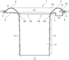
図1は、本発明に係るバグフィルター用空気増幅装置1の第1実施形態を模式的に示す模式斜視図である。図2は、本発明に係るバグフィルター用空気増幅装置1の第1実施形態を、側面から視た断面模式図である。
図1は、本発明に係るバグフィルター用空気増幅装置1の第1実施形態を模式的に示す模式斜視図である。図2は、本発明に係るバグフィルター用空気増幅装置1の第1実施形態を、側面から視た断面模式図である。
本発明に係るバグフィルター用空気増幅装置1は、大別して、空気増幅部11と、圧縮空気導入部12と、を少なくとも備える。そして、空気増幅部11は、外部空気誘引口111と、増幅空気排出口112と、側壁113と、を備え、圧縮空気導入部12は、圧縮空気導入口121と、圧縮空気噴射孔122と、圧縮空気誘導壁123と、必要に応じて遮蔽板124と、を備える。以下、各部および圧縮空気導入部12の構造的特徴について、詳細に説明する。
(1)空気増幅部11
空気増幅部11は、後述する圧縮空気導入部12から噴射された圧縮空気によるコアンダ効果を利用して、空気を増幅させる部分である。
空気増幅部11は、後述する圧縮空気導入部12から噴射された圧縮空気によるコアンダ効果を利用して、空気を増幅させる部分である。
(a)外部空気誘引口111
外部空気誘引口111は、コアンダ効果によって、外部の空気を誘引する部分である。誘引される外部空気の流れを、図2符号F3で示す。外部空気誘引口111の開口面積や開口形状は、本発明の効果を損なわない限り特に限定されず、目的のバグフィルターに用いる濾布の大きさなどに合わせて自由に設計することができる。一例を挙げると、例えば、バグフィルターの濾布の直径が150mm程度の場合、内径70~80mmに外部空気誘引口111を設計することができる。
外部空気誘引口111は、コアンダ効果によって、外部の空気を誘引する部分である。誘引される外部空気の流れを、図2符号F3で示す。外部空気誘引口111の開口面積や開口形状は、本発明の効果を損なわない限り特に限定されず、目的のバグフィルターに用いる濾布の大きさなどに合わせて自由に設計することができる。一例を挙げると、例えば、バグフィルターの濾布の直径が150mm程度の場合、内径70~80mmに外部空気誘引口111を設計することができる。
(b)増幅空気排出口112
増幅空気排出口112は、増幅された空気をバグフィルターへ向かって排出する部分である。排出される増幅された空気の流れを、図2符号F4で示す。増幅空気排出口112の開口面積や開口形状は、本発明の効果を損なわない限り特に限定されず、目的のバグフィルターに用いる濾布の大きさなどに合わせて自由に設計することができる。一例を挙げると、例えば、バグフィルターの濾布の直径が150mm程度の場合、内径70~80mmに増幅空気排出口112を設計することができる。
増幅空気排出口112は、増幅された空気をバグフィルターへ向かって排出する部分である。排出される増幅された空気の流れを、図2符号F4で示す。増幅空気排出口112の開口面積や開口形状は、本発明の効果を損なわない限り特に限定されず、目的のバグフィルターに用いる濾布の大きさなどに合わせて自由に設計することができる。一例を挙げると、例えば、バグフィルターの濾布の直径が150mm程度の場合、内径70~80mmに増幅空気排出口112を設計することができる。
従来のバグフィルター用空気増幅装置では、外部空気誘引口111と増幅空気排出口112は、同一の開口面積および開口形状に設計されていた(例えば、特許文献3図3参照)。本発明に係るバグフィルター用空気増幅装置1においても、従来と同様に、外部空気誘引口111と増幅空気排出口112を、同一の開口面積および開口形状に設計することも可能であるが、図3に示す第2実施形態のように、増幅空気排出口112の断面面積を、外部空気誘引口111の断面面積より広く設計することが好ましい。増幅空気排出口112の断面面積を、外部空気誘引口111の断面面積より広く設計することで、空気増幅効率を更に向上させることができる。
増幅空気排出口112の断面面積を、外部空気誘引口111の断面面積より広く設計する方法としては、後述する側壁113の所定部分を外側へ広げる方法がある。この際、圧縮空気噴射孔122から噴射される圧縮空気によるコアンダ効果が少なくとも持続される部位において、側壁113を外側へ広げることが好ましい(図3符号W参照)。コアンダ効果が少なくとも持続される部位において、側壁113を外側へ広げることで、確実に、空気増幅効率を向上させることができる。
(c)側壁113
側壁113は、外部空気誘引口111から増幅空気排出口112へ渡って設けられ、外部空気誘引口111から誘引された外部空気と、後述する圧縮空気噴射孔122から噴射された圧縮空気と、を増幅空気排出口112へ誘導するために、筒状を呈する。側壁113の長さなどの具体的態様は、本発明の効果を損なわない限り特に限定されず、目的のバグフィルターなどに合わせて自由に設計することができる。
側壁113は、外部空気誘引口111から増幅空気排出口112へ渡って設けられ、外部空気誘引口111から誘引された外部空気と、後述する圧縮空気噴射孔122から噴射された圧縮空気と、を増幅空気排出口112へ誘導するために、筒状を呈する。側壁113の長さなどの具体的態様は、本発明の効果を損なわない限り特に限定されず、目的のバグフィルターなどに合わせて自由に設計することができる。
(2)圧縮空気導入部12
圧縮空気導入部12は、後述する圧縮空気導入管2から送られてくる圧縮空気を、本発明に係るバグフィルター用空気増幅装置1の内部へ導入するための部位である。
圧縮空気導入部12は、後述する圧縮空気導入管2から送られてくる圧縮空気を、本発明に係るバグフィルター用空気増幅装置1の内部へ導入するための部位である。
(a)圧縮空気導入部12の構造的特徴
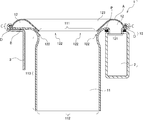
本発明に係る空気増幅装置1の圧縮空気導入部12は、第1部材Aと、第2部材Bと、シム部材Dと、からなることを特徴とする。第1部材Aと、第2部材Bとは、加締め部Cにおいて継合される。そして、シム部材Dは、この加締め部Cにおいて、第1部材Aと第2部材Bに挟持された状態で備えられる。
本発明に係る空気増幅装置1の圧縮空気導入部12は、第1部材Aと、第2部材Bと、シム部材Dと、からなることを特徴とする。第1部材Aと、第2部材Bとは、加締め部Cにおいて継合される。そして、シム部材Dは、この加締め部Cにおいて、第1部材Aと第2部材Bに挟持された状態で備えられる。
従来の空気増幅装置では、圧縮空気噴射孔122の部分にスペーサー(図示しない)などを配置して、圧縮空気噴射孔122の隙間を確保していた。しかし、この方法は、本来、密接している第1部材Aと第2部材Bとの間に、スペーサーによって無理やり隙間を形成しているため、第1部材Aと第2部材Bとが密接状態へ戻ろうとする力が発生し、スペーサーが配置されていない部分の第1部材Aが落ち込み、スペーサー部分の隙間と、スペーサーの無い部分の隙間の大きさに差が生じるという問題があった。また、スペーサーによって、圧縮空気の流れが妨げられるといった問題もあった。これらが、圧縮空気噴射孔122からの圧縮空気の噴射能力の低下、ひいては、空気増幅能力の低下につながっていた。
一方、本発明に係るバグフィルター用空気増幅装置1では、従来の空気増幅装置の構造から発想を転換し、加締め部Cにおいて、第1部材Aと第2部材Bとの間に、圧縮空気噴射孔122の幅を調整するためのシム部材Dを配設することで、従来の問題を解消することに成功した。即ち、加締め部Cにおいて、第1部材Aと第2部材Bとの間にシム部材Dを配設するため、第1部材Aと第2部材Bとが密接状態へ戻ろうとする力は発生しない。そのため、圧縮空気噴射孔122の隙間を所望の大きさで一定に保つことができる。また、圧縮空気噴射孔122の隙間には、何ら障害物は存在しないため、圧縮空気の流れが妨げられるといった問題も生じない。更に、シム部材Dの厚さを変更するだけで、圧縮空気噴射孔122の幅を容易に変更することが可能である。
図4~6は、本発明に係るバグフィルター用空気増幅装置1を上部側から視た平面模式図である。本発明に係る空気増幅装置1に用いるシム部材Dの形態は、本発明の効果を損なわない限り特に限定されない。例えば、図4に示す第1実施形態のようにリング状にしてもよいし、図5に示す第3実施形態や図6に示す第4実施形態のように、複数の円弧状のシム部材Dを備えることもできる。
(b)圧縮空気導入口121
圧縮空気導入口121は、後述する圧縮空気導入管2から送られてくる圧縮空気を、圧縮空気導入部12の内部へ導入するための部位である。導入される圧縮空気の流れを、図2符号F1で示す。圧縮空気導入口121の開口面積や開口形状など具体的な態様は、本発明の効果を損なわない限り特に限定されず、目的のバグフィルターや接続する圧縮空気導入管2の形態などに合わせて自由に設計することができる。
圧縮空気導入口121は、後述する圧縮空気導入管2から送られてくる圧縮空気を、圧縮空気導入部12の内部へ導入するための部位である。導入される圧縮空気の流れを、図2符号F1で示す。圧縮空気導入口121の開口面積や開口形状など具体的な態様は、本発明の効果を損なわない限り特に限定されず、目的のバグフィルターや接続する圧縮空気導入管2の形態などに合わせて自由に設計することができる。
(c)圧縮空気噴射孔122
圧縮空気噴射孔122は、圧縮空気導入口121から導入された圧縮空気を、空気増幅部11へ噴射するための部位である。噴射される圧縮空気の流れを、図2符号F2で示す。なお、本発明の特徴を分かり易くするために、図面では、圧縮空気噴射孔122の隙間を、実際の装置に比べ誇張して表している。
圧縮空気噴射孔122は、圧縮空気導入口121から導入された圧縮空気を、空気増幅部11へ噴射するための部位である。噴射される圧縮空気の流れを、図2符号F2で示す。なお、本発明の特徴を分かり易くするために、図面では、圧縮空気噴射孔122の隙間を、実際の装置に比べ誇張して表している。
本発明に係るバグフィルター用空気増幅装置1では、圧縮空気噴射孔122から空気増幅部11への圧縮空気の噴射角度は、特に限定されないが、本発明では特に、外部空気の誘引方向に対して90°よりも小さい角度で噴射することが好ましい。このように、圧縮空気噴射孔122から空気増幅部11への圧縮空気が、外部空気の誘引方向に対して90°よりも小さい角度で噴射されることにより、従来のバグフィルター用空気増幅装置に比べ、空気増幅効率を飛躍的に向上させることができる。
なお、従来のバグフィルター用空気増幅装置のように、圧縮空気噴射孔122から空気増幅部11への圧縮空気の噴射角度を、外部空気の誘引方向に対して略垂直に設計することも可能である(図7に示す第5実施形態参照)。
圧縮空気噴射孔122を形成する間隙の幅は、本発明の効果を損なわない限り特に限定されず、導入される圧縮空気の量や目的の噴出速度などに合わせて自由に設計することができる。一例を挙げると、例えば、幅0.3~2mmに圧縮空気噴射孔122を形成する間隙を設計することができる。本発明に係るバグフィルター用空気増幅装置1の圧縮空気噴射孔122からは、超音速で圧縮空気が噴射される。この空気の噴射によって、外部空気誘引口111付近にはコアンダ効果が発生し、空気増幅部11へ外部空気が誘引される。その結果、非常に高効率で空気を増幅させることが可能である。
(d)圧縮空気誘導壁123
圧縮空気誘導壁123は、圧縮空気導入口121から導入された圧縮空気を、圧縮空気噴射孔122へ誘導するために、湾曲状の形態を成す。圧縮空気誘導壁123の具体的な形態は、圧縮空気導入口121から導入された圧縮空気を、圧縮空気噴射孔122へ誘導するために、少なくとも湾曲状の形態を成していれば、本発明の効果を損なわない限りその他の構造は特に限定されない。目的のバグフィルターや接続する圧縮空気導入管2の形態などに合わせて自由に設計することができる。
圧縮空気誘導壁123は、圧縮空気導入口121から導入された圧縮空気を、圧縮空気噴射孔122へ誘導するために、湾曲状の形態を成す。圧縮空気誘導壁123の具体的な形態は、圧縮空気導入口121から導入された圧縮空気を、圧縮空気噴射孔122へ誘導するために、少なくとも湾曲状の形態を成していれば、本発明の効果を損なわない限りその他の構造は特に限定されない。目的のバグフィルターや接続する圧縮空気導入管2の形態などに合わせて自由に設計することができる。
(e)遮蔽板124
図8は、本発明に係るバグフィルター用空気増幅装置1の第6実施形態を側面から視た断面模式図である。本発明に係る空気増幅装置1の圧縮空気導入部12の内部には、圧縮空気導入部12内部での圧縮空気の流動方向を遮蔽するように、遮蔽板124を備えることができる。なお、この遮蔽板124は、本発明に係るバグフィルター用空気増幅装置1においては必須ではないが、後述する実施例で示すように、空気増幅効率を向上させるためには、備えることが好ましい。
図8は、本発明に係るバグフィルター用空気増幅装置1の第6実施形態を側面から視た断面模式図である。本発明に係る空気増幅装置1の圧縮空気導入部12の内部には、圧縮空気導入部12内部での圧縮空気の流動方向を遮蔽するように、遮蔽板124を備えることができる。なお、この遮蔽板124は、本発明に係るバグフィルター用空気増幅装置1においては必須ではないが、後述する実施例で示すように、空気増幅効率を向上させるためには、備えることが好ましい。
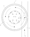
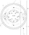
遮蔽板14を設置した場合の具体的な効果について、図9および図10を用いて説明する。図9は、本発明に係るバグフィルター用空気増幅装置1の第1実施形態における圧縮空気導入部12の内部を、上部側から視た断面模式図であり、図10は、本発明に係るバグフィルター用空気増幅装置1の第6実施形態における圧縮空気導入部12の内部を、上部側から視た断面模式図である。
図9に示すように、遮蔽板124を有さない第1実施形態に係るバグフィルター用空気増幅装置1では、後述する圧縮空気導入管2から送られてくる圧縮空気が、圧縮空気導入口121から導入され(図9中符号F1参照)、圧縮空気導入部12の内部を循環しながら、圧縮空気噴射孔122から圧縮空気が噴出される(図9中符号F2参照)。
一方、図10に示すように、遮蔽板124を有する第6実施形態に係る空気増幅装置1では、圧縮空気導入口121から導入された圧縮空気は、一部が遮蔽板124にぶつかって進行方向を逆向きに変化する(図10中符号F1a参照)。そして、遮蔽板124に遮蔽されなかった圧縮空気F1bと、進行方向が逆向きに変化した圧縮空気F1aは、圧縮空気導入部12の内部で衝突し、新たな圧力が発生する。そのため、この圧力によって、遮蔽板124を有さない場合に比べて、より多くの圧縮空気が圧縮空気噴射孔122から噴出される(図10中符号F2参照)。
本発明において、遮蔽板124の形態は、本発明の効果を損なわない限り自由に設計することができる。本発明では特に、圧縮空気導入部12内部の垂直方向の断面積に対し、30%以上の大きさに設計することが好ましい。この範囲の大きさに設計することで、圧縮空気導入部12の内部で十分な圧力を発生させることができる。
なお、本発明に係る空気増幅装置1では、遮蔽板124を用いて、圧縮空気導入部12内部を垂直方向に、全遮蔽してもよい。全遮蔽した場合、圧縮空気導入口121から導入された圧縮空気は、遮蔽板124に衝突することにより新たな圧力が発生し、圧縮空気噴射孔122から効率よく圧縮空気が噴射される。
また、圧縮空気導入部12の内部における遮蔽板124の設置方法も、本発明の効果を損なわない限り限定されず、自由な方法で設置することが可能である。例えば、図8の第6実施形態に係るバグフィルター用空気増幅装置1のように、シム部材Dに連設することができる。シム部材Dに連設することで、加締め部Cにおいて、固定することができるため、新たな固定具などを設ける必要がなく、脱着も容易に行うことができる。
更に、圧縮空気導入部12の内部における遮蔽板124の設置位置も、本発明の効果を損なわない限り限定されず、自由な位置に設置することが可能である。本発明では特に、図10の第6実施形態に係るバグフィルター用空気増幅装置1のように、圧縮空気導入口121における圧縮空気の導入直後の流動方向側に設けることが好ましい。この位置に設けることで、圧縮空気導入部12の内部で十分な圧力を発生させることができる。
<2.バグフィルター用空気増幅システム10>
図11は、本発明に係るバグフィルター用空気増幅システム10の第1実施形態を側面から視た断面模式図である。本発明に係るバグフィルター用空気増幅システム10は、前述した本発明に係るバグフィルター用空気増幅装置1と、圧縮空気導入管2と、を少なくとも備える。また、本発明に係るバグフィルター用空気増幅システム10には、固定手段3を備えることもできる。以下、各部について、詳細に説明する。なお、本発明に係るバグフィルター用空気増幅装置1の詳細は、前述と同様であるため、ここでは説明を割愛する。
図11は、本発明に係るバグフィルター用空気増幅システム10の第1実施形態を側面から視た断面模式図である。本発明に係るバグフィルター用空気増幅システム10は、前述した本発明に係るバグフィルター用空気増幅装置1と、圧縮空気導入管2と、を少なくとも備える。また、本発明に係るバグフィルター用空気増幅システム10には、固定手段3を備えることもできる。以下、各部について、詳細に説明する。なお、本発明に係るバグフィルター用空気増幅装置1の詳細は、前述と同様であるため、ここでは説明を割愛する。
(1)圧縮空気導入管2
圧縮空気導入管2は、空気増幅装置1の前記圧縮空気導入部12へ圧縮空気を導入する。圧縮空気導入管2の太さや長さなどの具体的な形態は、本発明の効果を損なわない限り特に限定されず、目的のバグフィルター、設置場所の形態などに合わせて自由に設計することができる。
圧縮空気導入管2は、空気増幅装置1の前記圧縮空気導入部12へ圧縮空気を導入する。圧縮空気導入管2の太さや長さなどの具体的な形態は、本発明の効果を損なわない限り特に限定されず、目的のバグフィルター、設置場所の形態などに合わせて自由に設計することができる。
また、圧縮空気導入管2の配置についても本発明の効果を損なわない限り特に限定されず、設置場所の形態などに合わせて自由に設計することができるが、本発明においては、バグフィルター用空気増幅装置1の圧縮空気導入部12に連通するように、圧縮空気導入部12の下部に設置することが好ましい。例えば、特許文献2に記載のコアンダインジェクターのように、外部空気誘引口の上部に、圧縮空気導入管を設置することも理論的には可能である。しかしながら、外部空気誘引口の上部に圧縮空気導入管を設置すると、外部空気誘引口からの外部空気の誘引の際に空気の流れの障害となり、誘引する空気量が低下する場合があり、空気増幅効果が低下する恐れがある。そのため、本発明においては、圧縮空気導入管2を圧縮空気導入部12の下部に設置することが好ましい。
更に、圧縮空気導入管2の具体的な断面形状についても、本発明の効果を損なわない限り特に限定されず、設置場所の形態などに合わせて自由に設計することができる。本発明においては特に、図11の第1実施形態に係るバグフィルター用空気増幅システム10のように、圧縮空気導入部12の圧縮空気導入管2との接続面と、圧縮空気導入管2の前記圧縮空気導入部12との接続面とが、互いに平行となるように設計することが好ましい。圧縮空気導入部12の圧縮空気導入管2との接続面と、圧縮空気導入管2の前記圧縮空気導入部12との接続面とが、互いに平行となるように設計することで、圧縮空気の漏出を防止することができる。
圧縮空気導入部12と圧縮空気導入管2との接続は、溶接により行うことも可能であるが(図示なし)、図11に示す第1実施形態のように、パッキンPを用いてシールすることも可能である。パッキンPを用いて接続することにより、圧縮空気導入管2からバグフィルター用空気増幅装置1を容易に取り外すことが可能となり、破損による単品交換や、緊急に濾布穴を塞ぐ必要が生じた場合などに対応可能である。
加えて、本発明に係るバグフィルター用空気増幅システム10に備える圧縮空気導入管2の数も、本発明の効果を損なわない限り特に限定されず、設置場所の形態などに合わせて1本或いは2本以上の複数本、備えることも可能である。本発明では特に、圧縮空気導入管2の数は、1本にすることが好ましい。
(2)固定手段3
本発明に係るバグフィルター用空気増幅システム10には、バグフィルター用空気増幅装置1を固定する固定手段3を更に備えることも可能である。固定手段3は本発明においては必須ではないが、固定手段3を設けることで、バグフィルター用空気増幅装置1の水平性を保つことができる。
本発明に係るバグフィルター用空気増幅システム10には、バグフィルター用空気増幅装置1を固定する固定手段3を更に備えることも可能である。固定手段3は本発明においては必須ではないが、固定手段3を設けることで、バグフィルター用空気増幅装置1の水平性を保つことができる。
通常、バグフィルターのメンテナンスなどを行う際、バグフィルター用空気増幅システム10上を、人が移動する場合がある。図11に示す第1実施形態に係る本発明に係るバグフィルター用空気増幅システム10のように、バグフィルター用空気増幅装置1を固定する固定手段3を更に備えれば、人の重さによるバグフィルター用空気増幅装置1の傾き防止して、その水平性を維持することができ、その結果、優れた空気増幅効果を維持することができる。
以下、実施例に基づいて本発明を更に詳細に説明する。なお、以下に説明する実施例は、本発明の代表的な実施例の一例を示したものであり、これにより本発明の範囲が狭く解釈されることはない。
<実験例1>
実験例1では、バグフィルター用空気増幅装置1の圧縮空気導入部12の内部に遮蔽板124を備えた場合と、備えない場合とで、空気増幅効果が変化するか否かを調べた。具体的には、本発明に係るバグフィルター用空気増幅装置の例として、図2および図9に示す第1実施形態に係るバグフィルター用空気増幅装置(実施例1)、図8及び図10に示す第6実施形態に係るバグフィルター用空気増幅装置(実施例2)を用いて、空気増幅効率を比較した。
実験例1では、バグフィルター用空気増幅装置1の圧縮空気導入部12の内部に遮蔽板124を備えた場合と、備えない場合とで、空気増幅効果が変化するか否かを調べた。具体的には、本発明に係るバグフィルター用空気増幅装置の例として、図2および図9に示す第1実施形態に係るバグフィルター用空気増幅装置(実施例1)、図8及び図10に示す第6実施形態に係るバグフィルター用空気増幅装置(実施例2)を用いて、空気増幅効率を比較した。
(1)実験方法
実施例1及び2に係るバグフィルター用空気増幅装置1をそれぞれ9連にしたバグフィルター用空気増幅システムの圧縮空気導入管に、0.5MPaの圧縮空気を0.1秒間流し、増幅空気排出口からの空気圧を測定した。
実施例1及び2に係るバグフィルター用空気増幅装置1をそれぞれ9連にしたバグフィルター用空気増幅システムの圧縮空気導入管に、0.5MPaの圧縮空気を0.1秒間流し、増幅空気排出口からの空気圧を測定した。
空気圧の測定について図12を参照しながら簡単に説明する。空気圧の測定には、少なくとも増幅空気排出口の断面径の約2倍の径を有し、増幅空気排出口から排出される空気(図12、矢印F4参照)を受ける円板41と、1~10キログラムフォース(Kgf))の荷重に応じて1~10cmの変位を生じるばね42(図12、矢印F5参照)と、ばね42を介して円板41と接続された支持体43と、円板41の変位を記録するための変位計44と、を備える装置を使用した。ばねの最大変位から換算した荷重(Kgf)を空気圧の測定値とした。
(2)結果
結果を図13に示す。図13に示す通り、遮蔽板124を有さないバグフィルター用空気増幅装置を用いた実施例1に比べ、遮蔽板124を有するバグフィルター用空気増幅装置を用いた実施例2の方が、全体的に約1.5Kgf風圧が上昇し、安定した空気増幅効果が得られることが分かった。
結果を図13に示す。図13に示す通り、遮蔽板124を有さないバグフィルター用空気増幅装置を用いた実施例1に比べ、遮蔽板124を有するバグフィルター用空気増幅装置を用いた実施例2の方が、全体的に約1.5Kgf風圧が上昇し、安定した空気増幅効果が得られることが分かった。
1 バグフィルター用空気増幅装置
11 空気増幅部
111 外部空気誘引口
112 増幅空気排出口
113 側壁
12 圧縮空気導入部
A 第1部材
B 第2部材
C 加締め部
D シム部材
121 圧縮空気導入口
122 圧縮空気噴射孔
123 圧縮空気誘導壁
124 遮蔽板
10 バグフィルター用空気増幅システム
2 圧縮空気導入管
3 固定手段
41 円板
42 ばね
43 支持体
44 変位計
11 空気増幅部
111 外部空気誘引口
112 増幅空気排出口
113 側壁
12 圧縮空気導入部
A 第1部材
B 第2部材
C 加締め部
D シム部材
121 圧縮空気導入口
122 圧縮空気噴射孔
123 圧縮空気誘導壁
124 遮蔽板
10 バグフィルター用空気増幅システム
2 圧縮空気導入管
3 固定手段
41 円板
42 ばね
43 支持体
44 変位計
Claims (6)
- バグフィルターの逆洗に用いる空気増幅装置であって、
外部の空気を誘引する外部空気誘引口と、増幅された空気を排出する増幅空気排出口と、前記外部空気誘引口から前記増幅空気排出口へ渡って設けられた筒状の側壁と、が備えられた空気増幅部と、
圧縮された空気を導入する圧縮空気導入口と、圧縮空気を前記空気増幅部へ噴射する圧縮空気噴射孔と、前記圧縮空気導入口から導入された圧縮空気を前記圧縮空気噴射孔へ誘導する湾曲状の圧縮空気誘導壁と、が備えられた圧縮空気導入部と、
を少なくとも備え、
前記圧縮空気導入部は、
前記圧縮空気誘導壁を含む第1部材と、
前記空気増幅部へ連設された第2部材と、
前記第1部材と前記第2部材が継合される加締め部と、
該加締め部において、前記第1部材と前記第2部材に挟持され、前記圧縮空気噴射孔の幅を調整するためのシム部材と、
からなるバグフィルター用空気増幅装置。 - 前記シム部材は、リング状である請求項1記載のバグフィルター用空気増幅装置。
- 前記圧縮空気導入部の内部には、前記圧縮空気導入部内部での圧縮空気の流動方向を遮蔽するように、遮蔽板が備えられた請求項1または2に記載のバグフィルター用空気増幅装置。
- 前記遮蔽板は、前記シム部材に連設された請求項3記載のバグフィルター用空気増幅装置。
- 前記遮蔽板は、前記圧縮空気導入口における圧縮空気の導入直後の流動方向側に設けられた請求項3または4に記載のバグフィルター用空気増幅装置。
- バグフィルターの逆洗に用いる空気増幅システムであって、
請求項1から5のいずれか一項に記載の空気増幅装置と、
該空気増幅装置の前記圧縮空気導入部へ圧縮空気を導入する圧縮空気導入管と、
を少なくとも備えたバグフィルター用空気増幅システム。
Priority Applications (1)
| Application Number | Priority Date | Filing Date | Title |
|---|---|---|---|
| JP2015504222A JP5969686B2 (ja) | 2013-03-08 | 2014-02-14 | バグフィルター用空気増幅装置および該バグフィルター用空気増幅装置を用いたバグフィルター用空気増幅システム |
Applications Claiming Priority (2)
| Application Number | Priority Date | Filing Date | Title |
|---|---|---|---|
| JP2013046204 | 2013-03-08 | ||
| JP2013-046204 | 2013-03-08 |
Publications (1)
| Publication Number | Publication Date |
|---|---|
| WO2014136551A1 true WO2014136551A1 (ja) | 2014-09-12 |
Family
ID=51491076
Family Applications (1)
| Application Number | Title | Priority Date | Filing Date |
|---|---|---|---|
| PCT/JP2014/053505 Ceased WO2014136551A1 (ja) | 2013-03-08 | 2014-02-14 | バグフィルター用空気増幅装置および該バグフィルター用空気増幅装置を用いたバグフィルター用空気増幅システム |
Country Status (3)
| Country | Link |
|---|---|
| JP (1) | JP5969686B2 (ja) |
| TW (1) | TW201442775A (ja) |
| WO (1) | WO2014136551A1 (ja) |
Cited By (1)
| Publication number | Priority date | Publication date | Assignee | Title |
|---|---|---|---|---|
| CN106984127A (zh) * | 2017-05-31 | 2017-07-28 | 王常利 | 空气净化器及空气净化系统 |
Citations (2)
| Publication number | Priority date | Publication date | Assignee | Title |
|---|---|---|---|---|
| JP2008115847A (ja) * | 2006-11-01 | 2008-05-22 | Kwang Sup Cho | 空気増幅器を利用した圧縮空気噴射装置 |
| WO2011118862A1 (ko) * | 2010-03-24 | 2011-09-29 | 한국에너지기술연구원 | 이중 원주형 슬릿 탈진공기 분사노즐 및 이를 이용한 여과집진장치 탈진시스템 |
Family Cites Families (4)
| Publication number | Priority date | Publication date | Assignee | Title |
|---|---|---|---|---|
| DE3004453A1 (de) * | 1980-02-07 | 1981-08-13 | Intensiv-Filter Gmbh & Co Kg, 5620 Velbert | Zwei-stufen-injektor zur abgasreinigung von staubfiltern |
| DE19849639C1 (de) * | 1998-10-28 | 2000-02-10 | Intensiv Filter Gmbh | Coanda-Injektor und Druckgasleitung zum Anschluß eines solchen |
| JP3676722B2 (ja) * | 2001-10-23 | 2005-07-27 | 日本スピンドル製造株式会社 | 濾布式集塵機の清掃装置 |
| KR100928591B1 (ko) * | 2009-03-04 | 2009-11-24 | (주)이진엔지니어링 | 압축공기 분사장치 |
-
2014
- 2014-02-14 JP JP2015504222A patent/JP5969686B2/ja not_active Expired - Fee Related
- 2014-02-14 WO PCT/JP2014/053505 patent/WO2014136551A1/ja not_active Ceased
- 2014-03-05 TW TW103107337A patent/TW201442775A/zh unknown
Patent Citations (2)
| Publication number | Priority date | Publication date | Assignee | Title |
|---|---|---|---|---|
| JP2008115847A (ja) * | 2006-11-01 | 2008-05-22 | Kwang Sup Cho | 空気増幅器を利用した圧縮空気噴射装置 |
| WO2011118862A1 (ko) * | 2010-03-24 | 2011-09-29 | 한국에너지기술연구원 | 이중 원주형 슬릿 탈진공기 분사노즐 및 이를 이용한 여과집진장치 탈진시스템 |
Cited By (2)
| Publication number | Priority date | Publication date | Assignee | Title |
|---|---|---|---|---|
| CN106984127A (zh) * | 2017-05-31 | 2017-07-28 | 王常利 | 空气净化器及空气净化系统 |
| CN106984127B (zh) * | 2017-05-31 | 2019-06-28 | 王常利 | 空气净化器及空气净化系统 |
Also Published As
| Publication number | Publication date |
|---|---|
| JP5969686B2 (ja) | 2016-08-17 |
| TW201442775A (zh) | 2014-11-16 |
| JPWO2014136551A1 (ja) | 2017-02-09 |
Similar Documents
| Publication | Publication Date | Title |
|---|---|---|
| WO2008054107A1 (en) | Apparatus for supplying compressed air using air amplifier | |
| EP2091631B1 (en) | System configuration of pulsed cleaned panel-style filter elements and methods | |
| MX2011006851A (es) | Sistema y metodo para la remocion de materia en particulas a partir de un medio de filtro. | |
| JP6155534B2 (ja) | 圧縮空気噴射装置 | |
| US20150298041A1 (en) | Dust collector with monitor air filter | |
| JP6047523B2 (ja) | コアンダインジェクター | |
| JP5969686B2 (ja) | バグフィルター用空気増幅装置および該バグフィルター用空気増幅装置を用いたバグフィルター用空気増幅システム | |
| JP6499779B2 (ja) | バグフィルター用空気増幅装置および該バグフィルター用空気増幅装置を用いたバグフィルター用空気増幅システム | |
| JP2017136596A (ja) | 圧縮空気噴射装置 | |
| KR101643574B1 (ko) | 백필터 탈진용 분사노즐 | |
| KR101737269B1 (ko) | 구조를 개선한 블로우 파이프 및 이를 포함하는 집진기 | |
| JP2017115746A (ja) | フィルタ装置及びガスタービン設備 | |
| US11117139B2 (en) | Gas dedusting filter apparatus and process | |
| KR20150015194A (ko) | 디퓨져가 내장된 백필터 | |
| KR20120083258A (ko) | 공기증폭기를 이용한 압축공기 분사장치 | |
| KR200472211Y1 (ko) | 대용량 압축공기 분사장치 | |
| KR102917943B1 (ko) | 백필터 탈진장치를 구비한 집진기 | |
| JP2014171973A (ja) | 圧縮空気パルス射出用配管及びバグフィルター用空気増幅システム | |
| JP6090797B2 (ja) | 集塵装置 | |
| KR20210009725A (ko) | 집진장치 | |
| CN109838399B (zh) | 一种风机 | |
| KR101343122B1 (ko) | 백필터 분진제거 보조장치 | |
| KR20190090116A (ko) | 집진기용 공기 분사 장치 |
Legal Events
| Date | Code | Title | Description |
|---|---|---|---|
| 121 | Ep: the epo has been informed by wipo that ep was designated in this application |
Ref document number: 14759668 Country of ref document: EP Kind code of ref document: A1 |
|
| ENP | Entry into the national phase |
Ref document number: 2015504222 Country of ref document: JP Kind code of ref document: A |
|
| NENP | Non-entry into the national phase |
Ref country code: DE |
|
| 122 | Ep: pct application non-entry in european phase |
Ref document number: 14759668 Country of ref document: EP Kind code of ref document: A1 |