WO2014136192A1 - 減揺装置及びそれを用いた船舶 - Google Patents
減揺装置及びそれを用いた船舶 Download PDFInfo
- Publication number
- WO2014136192A1 WO2014136192A1 PCT/JP2013/055887 JP2013055887W WO2014136192A1 WO 2014136192 A1 WO2014136192 A1 WO 2014136192A1 JP 2013055887 W JP2013055887 W JP 2013055887W WO 2014136192 A1 WO2014136192 A1 WO 2014136192A1
- Authority
- WO
- WIPO (PCT)
- Prior art keywords
- gimbal
- flywheel
- vibration
- reduction device
- ship
- Prior art date
- Legal status (The legal status is an assumption and is not a legal conclusion. Google has not performed a legal analysis and makes no representation as to the accuracy of the status listed.)
- Ceased
Links
Images


Classifications
-
- B—PERFORMING OPERATIONS; TRANSPORTING
- B63—SHIPS OR OTHER WATERBORNE VESSELS; RELATED EQUIPMENT
- B63B—SHIPS OR OTHER WATERBORNE VESSELS; EQUIPMENT FOR SHIPPING
- B63B39/00—Equipment to decrease pitch, roll, or like unwanted vessel movements; Apparatus for indicating vessel attitude
- B63B39/04—Equipment to decrease pitch, roll, or like unwanted vessel movements; Apparatus for indicating vessel attitude to decrease vessel movements by using gyroscopes directly
-
- G—PHYSICS
- G01—MEASURING; TESTING
- G01C—MEASURING DISTANCES, LEVELS OR BEARINGS; SURVEYING; NAVIGATION; GYROSCOPIC INSTRUMENTS; PHOTOGRAMMETRY OR VIDEOGRAMMETRY
- G01C19/00—Gyroscopes; Turn-sensitive devices using vibrating masses; Turn-sensitive devices without moving masses; Measuring angular rate using gyroscopic effects
- G01C19/02—Rotary gyroscopes
- G01C19/04—Details
-
- Y—GENERAL TAGGING OF NEW TECHNOLOGICAL DEVELOPMENTS; GENERAL TAGGING OF CROSS-SECTIONAL TECHNOLOGIES SPANNING OVER SEVERAL SECTIONS OF THE IPC; TECHNICAL SUBJECTS COVERED BY FORMER USPC CROSS-REFERENCE ART COLLECTIONS [XRACs] AND DIGESTS
- Y10—TECHNICAL SUBJECTS COVERED BY FORMER USPC
- Y10T—TECHNICAL SUBJECTS COVERED BY FORMER US CLASSIFICATION
- Y10T74/00—Machine element or mechanism
- Y10T74/12—Gyroscopes
- Y10T74/1229—Gyroscope control
- Y10T74/1257—Damping
Definitions
- the present invention relates to a vibration reducing device that suppresses vibration and a ship using the same.
- Japanese Unexamined Patent Publication No. 7-215280 discloses a ship vibration damping device and a ship.
- This marine vibration damping device has a control moment gyroscope (100).
- the spin shaft (60) of the flywheel (1) of the gyro (100) is driven by a flat type spin motor (5), and is also driven by a gimbal (2) via a spin bearing (6).
- the gimbal (2) is supported by a support (8) via a gimbal shaft (3) and a gimbal bearing (7).
- the swing of the gimbal shaft (3) is braked by the disc brake (30).
- the disc brake (30) is composed of a gimbal shaft connecting fixed disc (9) and a support connecting fixed disc (10).
- the swing of the gimbal shaft (3) is braked by the powder brake (40) or the oil damper (11).
- the above-described ship vibration damping device supports a flywheel that rotates at high speed with a gimbal, and the gimbal swings due to the shaking of the ship, and transmits the gyro torque (counter torque) generated by the gyro effect to the hull. It is a device that reduces rolling.
- the gyro torque is braked by a braking device such as a disc brake, a powder brake, or an oil damper for the gimbal shaft.
- the inventors have found the following facts regarding the above-described vibration reduction device. That is, the above-described vibration reduction device is provided with a braking device that brakes the vibration of the gimbal shaft, but is not equipped with a mechanism for suddenly stopping the vibration reduction device in an emergency. In other words, when the gimbal of the vibration reduction device operates excessively, the suppression mechanism for the excessive gimbal operation is only the braking device. Therefore, for example, when the function of the braking device cannot be sufficiently performed due to a cause such as a temperature rise, the gimbal may vibrate violently, resulting in a malfunction of the vibration reducing device.
- the only way to stop the anti-vibration device is to turn off the motor power switch. After turning off the power switch, it is necessary to wait for a long time until the vibration reduction device stops.
- the situation of waves that the hull receives thereafter may change, and it is difficult to confirm the effect of the vibration reduction device using waves of the same condition as inputs to the hull. It is also difficult to experience the effect of reducing the vibrations over time.
- Japanese Patent Application Laid-Open No. 2010-256042 discloses a ship vibration reduction device.
- This marine vibration reduction device includes a flywheel, a gimbal, a motor, a gimbal support, a first damper, a motor driver, and a safety device.
- the gimbal rotatably supports the flywheel.
- the motor drives the flywheel.
- the gimbal support portion supports the gimbal so as to be swingable.
- the first damper brakes the swing of the gimbal.
- the motor driver supplies driving power to the motor.
- the safety device causes the motor driver to cut off the supply of drive power when the temperature of the first damper exceeds a predetermined temperature.
- the vibration reduction device of the present invention includes a flywheel, a gimbal, a gimbal support, a damper, and a lock mechanism.
- the gimbal rotatably supports the flywheel.
- the gimbal support portion supports the gimbal through a gimbal shaft so as to be swingable.
- the damper brakes the swing of the gimbal.
- the lock mechanism locks the swing of the gimbal.
- the lock mechanism may be provided to lock the swing of the gimbal shaft.
- the lock mechanism may include a disc brake that locks the swing of the gimbal shaft.
- the lock mechanism may be provided to lock the swing of the gimbal body.
- the lock mechanism may include an actuator that locks the swing of the gimbal body.
- the ship of the present invention includes a hull and the vibration reduction device according to any one of the above paragraphs provided on the hull.
- the ship vibration reduction device may be installed such that the gimbal axis is parallel to the pitch axis direction of the hull.
- the operation method of the ship vibration reduction device of the present invention includes a step of preparing the ship.
- the ship is provided with a hull and a vibration reducing device provided on the hull.
- the vibration reduction device includes a flywheel, a gimbal, a gimbal support, a damper, and a lock mechanism.
- the gimbal rotatably supports the flywheel.
- the gimbal support portion supports the gimbal through a gimbal shaft so as to be swingable.
- the damper brakes the swing of the gimbal.
- the lock mechanism locks the swing of the gimbal.
- the operation method of the marine vibration reduction device further includes a step of rotating the flywheel and a step of locking the swing of the gimbal with a lock mechanism when the gimbal swings due to the rotation of the flywheel and the swing of the hull. It has.
- an anti-vibration device capable of suddenly stopping in a short time and a ship using the same.
- an anti-vibration device capable of further improving safety and a ship using the same.
- an anti-vibration device capable of easily confirming the effect of anti-vibration and a ship using the anti-vibration device.
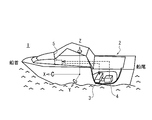
- FIG. 1 is an external view showing a configuration of a ship using the vibration reduction device according to the present embodiment.
- FIG. 2A is a schematic diagram illustrating a configuration example of the vibration reduction device according to the present embodiment.
- FIG. 2B is a schematic diagram illustrating another configuration example of the vibration reduction device according to the present embodiment.
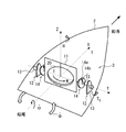
- FIG. 3 is a schematic diagram showing the operation of the vibration reduction device according to the present embodiment.
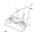
- FIG. 4 is a schematic diagram showing the operation of the vibration reduction device according to the present embodiment.
- FIG. 1 is an external view showing a configuration of a ship using the vibration reduction device according to the present embodiment.
- a boat is illustrated as the ship 1.
- the vibration reduction device according to the present embodiment can be applied not only to boats but also to other types of ships by changing the size and arrangement according to the type of ship.
- the ship 1 includes a hull 2, a vibration reduction device 3, a generator 4, and a control device 5.
- the rocking device 3 is provided in the hull 2 and is fixed in the hull 2.
- the vibration reduction device 3 is an anti-rolling system that suppresses the vibration of the hull 2. Details thereof will be described later.
- the generator 4 is provided in the hull 2 and supplies power to the vibration reduction device 3.
- the control device 5 is an information processing device exemplified by a computer, and is supplied with power from, for example, the generator 4 and controls the operation of the vibration reduction device 3 based on a user operation or a software command. Since the ship 1 has such a configuration, the operation / effect of the vibration reduction device 3 described later can be achieved.
- FIG. 2A is a schematic diagram illustrating a configuration example of the vibration reduction device according to the present embodiment.
- description of the generator 4 is abbreviate
- the vibration reduction device 3 includes a flywheel 20, a gimbal 11, a gimbal support portion 12, a damper 13, and a lock mechanism 14.
- the flywheel 20 is provided in the gimbal 11.
- the gimbal 11 supports the flywheel 20 so that the flywheel 20 can rotate around the rotation shaft 17.
- the flywheel 20 is driven by the motor 16 mounted on the gimbal 11 and rotates around the rotation shaft 17.
- the control device 5 controls the rotation of the flywheel 20 by controlling the power supply of the generator 4 to the motor 16.
- the gimbal support portion 12 supports the gimbal 11 via the gimbal shaft 15 so that the gimbal 11 can swing around the gimbal shaft (gimbal shaft) 15.
- the damper 13 brakes the swing of the gimbal 11 via the gimbal shaft 15.
- the damper 13 is exemplified by a braking mechanism using a fluid resistance of hydraulic oil and a braking mechanism such as a disc brake.
- the lock mechanism 14 locks the swing (gimbal operation) of the gimbal 11. That is, the lock mechanism 14 stops the swing (gimbal operation) of the gimbal 11 in a very short time, and maintains the stopped state.
- the lock mechanism 14 is exemplified by a mechanism using a disc brake and a mechanism using an actuator. In the mechanism using the disc brake, the brake disc is mounted on the gimbal shaft 15 of the gimbal 11, and the rotation of the brake disc, that is, the rotation of the gimbal shaft 15 is stopped by the brake pad, thereby locking the swing of the gimbal 11.
- a hydraulic / pneumatic or electric actuator is directly connected to the main body of the gimbal 11 (a casing containing the flywheel 20), and a load is applied to the main body of the gimbal 11 to swing the actuator. By stopping, rocking of the gimbal 11 is locked.
- the control device 5 controls the operation of the lock mechanism 14 by controlling the power supply of the generator 4 to the lock mechanism 14.
- This figure schematically shows an example of a lock mechanism that is locked by a disc brake as the lock mechanism 14.
- a disc including a brake disc 14a mounted on the gimbal shaft 15 of the gimbal 11 and a drive unit 14b (including a pad, a piston, and a caliper) that locks the operation of the brake disc 14a as the lock mechanism 14.
- a brake is used.
- the lock mechanism 14 can lock the swing of the gimbal shaft 15 and can lock the swing of the gimbal 11.
- the size and number of brake disks 14a may be increased according to the required brake strength.
- Such a disc brake is preferable because it has a simple structure and is easy to manufacture and attach.
- a locking mechanism 14 for sudden stop is attached to the vibration reduction device 3 as a separate body.
- the vibration reduction device 3 it is possible to multiplex the safety device function for stopping the flywheel 20.
- the rocking mechanism 3 can be stopped safely and in a short time by the lock mechanism 14.
- the lock mechanism 14 since the lock mechanism 14 is specialized for the stop function, it is not necessary to have a braking function, and the structure can be relatively simplified. Thereby, the apparatus can be miniaturized.
- the vibration reduction device 3 is arranged so that the rotation center 18 of the flywheel 20 overlaps the hull center line of the hull 2. (However, when two anti-vibration devices 3 are arranged, they need not overlap. In that case, two are arranged at equidistant positions around the X axis in the Y axis direction. 2 is parallel to the rotation axis 15 of the vibration reduction device 3.)
- the rotation center 18 of the flywheel 20 is the origin
- the bow direction is the X axis
- the vertical direction is the Z axis
- X The direction perpendicular to the axis and the Z axis is taken as the Y axis.
- the vibration reduction device 3 is arranged so that the gimbal shaft 15 is perpendicular to the X-axis direction. In other words, the vibration reduction device 3 is arranged so that the gimbal shaft 15 is parallel to the Y-axis direction. Further, the vibration reduction device 3 is arranged so that a line obtained by virtually extending the gimbal shaft 15 into the gimbal 11 passes through the rotation center 18 of the flywheel 20 (so as to intersect the rotation shaft 17). Further, the vibration reduction device 3 is arranged so that the rotating shaft 17 is parallel to the Z-axis direction when the hull 2 is on the still water surface.
- the lock mechanism 14 may be a mechanism using an actuator as described above.
- FIG. 2B is a schematic diagram illustrating a configuration example of the vibration reduction device according to the present embodiment.
- description of the generator 4 and the control apparatus 5 is abbreviate
- the example of this figure is different from the example of FIG. 2A in that the lock mechanism 14 uses an actuator.
- the lock mechanism 14 includes an actuator 14c and a stopper 14d.
- the actuator 14c is a hydraulic / pneumatic or electric actuator.
- the stopper 14d is connected to the actuator 14c.
- the stopper 14d is pressed against the main body of the gimbal 11 by the actuator 14c when the lock mechanism 14 is operated.
- the lock mechanism 14 applies a load to the main body of the gimbal 11 and stops the swinging thereof, thereby locking the swinging of the gimbal 11.
- the anti-vibration device 3 generates an anti-rolling moment T according to the following principle, and functions as an anti-oscillation device for the ship 1.
- the flywheel 20 is rotated by the rotation of the motor 16.
- the angular momentum H of the flywheel 10 is expressed by Equation (1).
- H I ⁇ ⁇ (1)
- FIG. 3 shows a case where the hull 2 is swung around the X axis by a wave at a rotational speed of ⁇ ⁇ around the X axis (counterclockwise as viewed from the stern).
- the flywheel 20 is held by a gimbal 11 whose Y axis is a gimbal shaft 15, and is fixed to the hull 2 via a gimbal support portion 12.
- the flywheel 20 cannot rotate freely around the X axis, and rotates around the X axis at the same rotation speed ⁇ as the hull 2.
- the swing torque TG of the formula (3) is generated around the Y axis on the same principle as that of the moment T.
- T G H ⁇ ⁇ ⁇ (3)
- the rotation of the flywheel 20 is generated by the swing torque TG .
- the flywheel 20 rotates at a rotational speed of ⁇ around the Y axis by the swing torque TG .
- FIG. 4 shows a case where the flywheel 10 rotates at a rotational speed of ⁇ ⁇ around the axis.
- the generated moment T always acts as the anti-rolling moment in the opposite direction to the swing of the hull 2, and the swing of the hull 2 is suppressed.
- the user or software operates the lock mechanism 14 via the control device 5.
- the lock mechanism 14 locks the swing (gimbal operation) of the gimbal 11. 2 to 4, the lock mechanism 14 (disc brake) strongly holds the brake disc 14a attached to the gimbal shaft 15 by the drive unit 14b. Accordingly, the lock mechanism 14 stops the rotation of the brake disc 14a, that is, the gimbal shaft 15. As a result, the swing operation of the gimbal 11 is stopped in an extremely short time (rapidly stopped).
- the swing operation of the gimbal 11 can be suddenly stopped during the swing suppression operation.
- the vibration reduction device 3 of the present embodiment has the lock mechanism 14.
- the locking mechanism 14 can lock the swinging operation of the gimbal 11 regardless of the phase of the swinging gimbal 11 when the damper 13 fails. Thereby, even when the damper 13 breaks down, it is possible to prevent the vibration reduction device 3 from being damaged.
- the damper 13 and the lock mechanism 14 are separated and attached to the vibration reduction device 3, so that even if the damper 13 breaks down, the vibration reduction device 3 is safely stopped by the lock mechanism 14. Can be made. Thereby, the vibration reduction device 3 can be made a safer device.
- the vibration reduction device of the present embodiment can be used to reduce the vibration of a gondola, a ropeway, a monorail, a crane load, etc. in addition to a ship.
Landscapes
- Engineering & Computer Science (AREA)
- Physics & Mathematics (AREA)
- General Physics & Mathematics (AREA)
- Radar, Positioning & Navigation (AREA)
- Remote Sensing (AREA)
- Chemical & Material Sciences (AREA)
- Combustion & Propulsion (AREA)
- Mechanical Engineering (AREA)
- Ocean & Marine Engineering (AREA)
- Vibration Prevention Devices (AREA)
- Braking Arrangements (AREA)
Abstract
Description
図1は、本実施の形態に係る減揺装置を用いた船舶の構成を示す外観図である。ここでは、船舶1としてボートを例示している。ただし、本実施の形態に係る減揺装置はボートだけでなく、船舶の種類に合わせたサイズや配置などの変更を行うことで、他の種類の船舶にも適用可能である。船舶1は、船体2と、減揺装置3と、発電機4と、制御装置5とを具備している。
1.揺動抑制動作
減揺装置3は以下の原理に従いアンチローリングモーメントTを発生し、船舶1の減揺装置として機能する。フライホイール20は、モータ16の回転により自転している。自転するフライホイール20のZ軸まわりの慣性モーメントをI、自転速度をωとすると、フライホイール10の持つ角運動量Hは式(1)のようになる。
H=I×ω (1)
この状態において、フライホイール10をY軸まわりにθ・なる回転速度で回転させる場合を考える。その場合、X軸まわりに式(2)の大きさのモーメントTが発生する。
T=H×θ・ (2)
すなわち、フライホイール10はX軸まわりにTなるモーメントで回転しようとする。なお、X軸、Y軸、Z軸の相対関係は不変である。
TG=H×φ・ (3)
その揺動トルクTGにより、フライホイール20の回転が発生する。すなわち、その揺動トルクTGにより、フライホイール20はY軸まわりにθ・なる回転速度にて回転する。図4は、フライホイール10が軸まわりにθ・なる回転速度にて回転する場合を示している。フライホイール10がY軸まわりにθ・なる回転速度にて回転すると、上述されたように、フライホイール10の角運動量Hとの作用により、X軸まわりにアンチローリングモーメントT(T=H×θ・)が発生する。しかし、フライホイール10はジンバル11にて船体2に固定されているので、そのモーメントTは船体2の揺動に対抗する方向に作用する。その結果、船体2の揺動とモーメントTとが打ち消し合い、船体2の揺動が抑制される。
一方、船体2の揺動が逆方向の場合は全てが逆方向となり、発生するモーメントTも逆方向となる。そして、その場合にも、船体2の揺動とモーメントTとが打ち消し合い、船体2の揺動が抑制される。
上記1.揺動抑制動作の最中に、ジンバル11の揺動作動を急停止させたい事情が発生した場合(例示:減揺装置3の効果確認、ダンパ13の不調)を考える。その事情の発生は、ユーザが把握しても良いし、図示されないセンサ(例示:ダンパ13の温度センサ)などで検出しても良い。センサなどの場合、その検出信号は制御装置5に出力される。
Claims (8)
- フライホイールと、
前記フライホイールを回転可能に支持するジンバルと、
ジンバル軸を介して前記ジンバルを揺動可能に支持するジンバル支持部と、
前記ジンバルの揺動を制動するダンパと、
前記ジンバルの揺動をロックするロック機構と
を具備する
減揺装置。 - 請求項1に記載の減揺装置において、
前記ロック機構は、前記ジンバル軸の揺動をロックするように設けられている
減揺装置。 - 請求項2に記載の減揺装置において、
前記ロック機構は、前記ジンバル軸の揺動をロックするディスクブレーキを含む
減揺装置。 - 請求項1に記載の減揺装置において、
前記ロック機構は、前記ジンバル本体の揺動をロックするように設けられている
減揺装置。 - 請求項4に記載の減揺装置において、
前記ロック機構は、前記ジンバル本体の揺動をロックするアクチュエータを含む
減揺装置。 - 船体と、
前記船体に設けられた請求項1乃至5のいずれか一項に記載の減揺装置と
を具備する
船舶。 - 請求項6に記載の船舶において、
前記船舶用減揺装置は、ジンバル軸が前記船体のピッチ軸方向と平行になるように設置される
船舶。 - 船舶の減揺装置の動作方法であって、
船舶を準備するステップと、
ここで、前記船舶は、
船体と、
前記船体に設けられた前記減揺装置と
を具備し、
前記減揺装置は、
フライホイールと、
前記フライホイールを回転可能に支持するジンバルと、
ジンバル軸を介して前記ジンバルを揺動可能に支持するジンバル支持部と、
前記ジンバルの揺動を制動するダンパと、
前記ジンバルの揺動をロックするロック機構と
を備え、
前記フライホイールを自転させるステップと、
前記フライホイールの自転及び前記船体の揺動により前記ジンバルが揺動するとき、前記ロック機構で前記ジンバルの揺動をロックするステップと
を具備する
船舶の減揺装置の動作方法。
Priority Applications (3)
| Application Number | Priority Date | Filing Date | Title |
|---|---|---|---|
| US13/978,993 US9452810B2 (en) | 2013-03-04 | 2013-03-04 | Rolling motion reducing apparatus for a ship |
| JP2013530261A JP5646066B1 (ja) | 2013-03-04 | 2013-03-04 | 減揺装置及びそれを用いた船舶 |
| PCT/JP2013/055887 WO2014136192A1 (ja) | 2013-03-04 | 2013-03-04 | 減揺装置及びそれを用いた船舶 |
Applications Claiming Priority (1)
| Application Number | Priority Date | Filing Date | Title |
|---|---|---|---|
| PCT/JP2013/055887 WO2014136192A1 (ja) | 2013-03-04 | 2013-03-04 | 減揺装置及びそれを用いた船舶 |
Publications (1)
| Publication Number | Publication Date |
|---|---|
| WO2014136192A1 true WO2014136192A1 (ja) | 2014-09-12 |
Family
ID=51420271
Family Applications (1)
| Application Number | Title | Priority Date | Filing Date |
|---|---|---|---|
| PCT/JP2013/055887 Ceased WO2014136192A1 (ja) | 2013-03-04 | 2013-03-04 | 減揺装置及びそれを用いた船舶 |
Country Status (3)
| Country | Link |
|---|---|
| US (1) | US9452810B2 (ja) |
| JP (1) | JP5646066B1 (ja) |
| WO (1) | WO2014136192A1 (ja) |
Families Citing this family (14)
| Publication number | Priority date | Publication date | Assignee | Title |
|---|---|---|---|---|
| JP6290142B2 (ja) * | 2015-07-07 | 2018-03-07 | 東明工業株式会社 | 減揺装置、および、船舶 |
| KR101668797B1 (ko) | 2016-02-02 | 2016-10-25 | 주식회사 삼미정공 | 해상 운송수단용 관성안정기 |
| WO2017135588A2 (ko) * | 2016-02-02 | 2017-08-10 | 주식회사 삼미정공 | 해상 운송수단용 관성안정기 및 이의 제어방법 |
| KR101831157B1 (ko) | 2016-08-30 | 2018-04-04 | 재단법인한국조선해양기자재연구원 | 발전시스템과 댐핑 장치가 구비된 선박용 자이로 스테빌라이저 및 이의 제어 방법 |
| WO2019232371A1 (en) * | 2018-05-31 | 2019-12-05 | Grady Smith | Gyroscopic boat roll stablizer |
| DE102018131113B4 (de) | 2018-12-06 | 2022-07-28 | ConVi GmbH | Wasserfahrzeug |
| EP4079625A1 (en) * | 2019-04-03 | 2022-10-26 | Wavetamer LLC | Braking system for gyroscopic boat roll stabilizer |
| NO345263B1 (en) * | 2019-10-21 | 2020-11-23 | Sleipner Motor As | Gyro stabilizer |
| AU2021231492C1 (en) | 2020-03-02 | 2024-06-20 | Wavetamer Llc | Gyroscopic boat roll stabilizer with bearing cooling |
| US11807344B2 (en) | 2020-09-30 | 2023-11-07 | Wavetamer Llc | Gyroscopic roll stabilizer with flywheel cavity seal arrangement |
| EP4204296B1 (en) | 2020-09-30 | 2024-05-08 | Wavetamer LLC | Gyroscopic roll stabilizer with flywheel shaft through passage |
| EP4429941B1 (en) * | 2021-11-08 | 2026-02-11 | Src Group As | Fairlead braking unit |
| WO2023182889A1 (en) * | 2022-03-22 | 2023-09-28 | Moray Innovation As | Fairlead locking system and method of operation |
| WO2025184158A1 (en) * | 2024-02-26 | 2025-09-04 | Seakeeper, Inc. | Parking pawl safety latch system |
Citations (1)
| Publication number | Priority date | Publication date | Assignee | Title |
|---|---|---|---|---|
| JP2000304541A (ja) * | 1999-04-21 | 2000-11-02 | Mitsubishi Heavy Ind Ltd | 安全機構を有する減揺装置 |
Family Cites Families (10)
| Publication number | Priority date | Publication date | Assignee | Title |
|---|---|---|---|---|
| US2202162A (en) * | 1936-11-21 | 1940-05-28 | Minorsky Nicolai | Antirolling stabilization of ships |
| US3395667A (en) * | 1966-06-16 | 1968-08-06 | Curtiss Wright Corp | Control system for ship roll stabilization |
| JP2813540B2 (ja) | 1994-02-02 | 1998-10-22 | 三菱重工業株式会社 | 船舶用動揺制振装置及び船舶 |
| US5628267A (en) | 1993-11-01 | 1997-05-13 | Mitsubishi Jukogyo Kabushiki Kaisha | Oscillation suppression device and ship provided with the same |
| US6973847B2 (en) * | 2003-06-04 | 2005-12-13 | Gearloose Engineering, Inc. | Gyroscopic roll stabilizer for boats |
| US20090114136A1 (en) * | 2003-09-19 | 2009-05-07 | Seagyro Pty Ltd | Vessel Stabilization Apparatus and Method |
| US7240630B2 (en) * | 2003-10-08 | 2007-07-10 | Marine Motion Control, Llc | Gyrostabilizer for small boats |
| WO2006022847A2 (en) * | 2004-03-25 | 2006-03-02 | Exxonmobil Upstream Research Company | Hydrogyro ship stabilizer and method for stabilizing a vessel |
| JP2007183356A (ja) * | 2006-01-05 | 2007-07-19 | Casio Comput Co Ltd | 防振装置 |
| JP4782216B2 (ja) | 2009-04-21 | 2011-09-28 | 三菱重工業株式会社 | 船舶の減揺装置 |
-
2013
- 2013-03-04 JP JP2013530261A patent/JP5646066B1/ja active Active
- 2013-03-04 WO PCT/JP2013/055887 patent/WO2014136192A1/ja not_active Ceased
- 2013-03-04 US US13/978,993 patent/US9452810B2/en active Active
Patent Citations (1)
| Publication number | Priority date | Publication date | Assignee | Title |
|---|---|---|---|---|
| JP2000304541A (ja) * | 1999-04-21 | 2000-11-02 | Mitsubishi Heavy Ind Ltd | 安全機構を有する減揺装置 |
Also Published As
| Publication number | Publication date |
|---|---|
| JP5646066B1 (ja) | 2014-12-24 |
| JPWO2014136192A1 (ja) | 2017-02-09 |
| US20140245939A1 (en) | 2014-09-04 |
| US9452810B2 (en) | 2016-09-27 |
Similar Documents
| Publication | Publication Date | Title |
|---|---|---|
| JP5646066B1 (ja) | 減揺装置及びそれを用いた船舶 | |
| US20080303363A1 (en) | Energy storage and gyroscopic stabilizing system | |
| EP1639314A1 (en) | Gyroscopic roll stabilizer for boats | |
| JP2010048200A5 (ja) | ||
| EP3817976A1 (en) | Boat stabilization system | |
| JP5102752B2 (ja) | 船外機制御装置およびそれを備えた船舶 | |
| JP5945783B2 (ja) | 船舶のヘルム装置 | |
| JP2017171263A (ja) | 船舶 | |
| CN205906175U (zh) | 一种双飞轮减摇器 | |
| KR101261867B1 (ko) | 포드형 추진기 및 이를 구비하는 선박 | |
| JP2004182096A (ja) | 船舶、船舶の航行装置、船舶の舵角制御装置および船舶の舵角制御方法 | |
| CN110654412A (zh) | 抑制高速列车侧滚、点头、摇头行为的主被动复合控制系统 | |
| JP6397844B2 (ja) | 船舶 | |
| WO2017164392A1 (ja) | 船舶 | |
| JP2017024667A (ja) | 電動舵取機用駆動装置、電動舵取機構、電動舵取ユニット及び船舶 | |
| JP2016060245A (ja) | 車両用ステアリング装置 | |
| JP2019107984A (ja) | 操舵装置及び船舶 | |
| US7238065B2 (en) | Method and arrangement for function test of a steering for a propeller drive on a boat | |
| CN106628040A (zh) | 一种双飞轮减摇器及其减摇实现方法 | |
| JP2024092325A (ja) | 吊荷旋回制御装置 | |
| JP7185536B2 (ja) | 回転翼駆動装置 | |
| JP2017013788A (ja) | 電動舵取ユニット、電動舵取機用駆動制御装置、電動舵取機構及び船舶 | |
| JP2006103490A (ja) | ポッド推進器を備えた船舶 | |
| KR20130136040A (ko) | 동요 안정화 자이로스코프 | |
| JP7702845B2 (ja) | 操船システム、船舶制御装置、船舶制御方法およびプログラム |
Legal Events
| Date | Code | Title | Description |
|---|---|---|---|
| ENP | Entry into the national phase |
Ref document number: 2013530261 Country of ref document: JP Kind code of ref document: A |
|
| WWE | Wipo information: entry into national phase |
Ref document number: 13978993 Country of ref document: US |
|
| 121 | Ep: the epo has been informed by wipo that ep was designated in this application |
Ref document number: 13877281 Country of ref document: EP Kind code of ref document: A1 |
|
| NENP | Non-entry into the national phase |
Ref country code: DE |
|
| 122 | Ep: pct application non-entry in european phase |
Ref document number: 13877281 Country of ref document: EP Kind code of ref document: A1 |