WO2014133185A1 - 磁気共鳴イメージング装置及び傾斜磁場コイル - Google Patents
磁気共鳴イメージング装置及び傾斜磁場コイル Download PDFInfo
- Publication number
- WO2014133185A1 WO2014133185A1 PCT/JP2014/055318 JP2014055318W WO2014133185A1 WO 2014133185 A1 WO2014133185 A1 WO 2014133185A1 JP 2014055318 W JP2014055318 W JP 2014055318W WO 2014133185 A1 WO2014133185 A1 WO 2014133185A1
- Authority
- WO
- WIPO (PCT)
- Prior art keywords
- cooling pipe
- magnetic field
- axis direction
- center
- piped
- Prior art date
- Legal status (The legal status is an assumption and is not a legal conclusion. Google has not performed a legal analysis and makes no representation as to the accuracy of the status listed.)
- Ceased
Links
Images






Classifications
-
- G—PHYSICS
- G01—MEASURING; TESTING
- G01R—MEASURING ELECTRIC VARIABLES; MEASURING MAGNETIC VARIABLES
- G01R33/00—Arrangements or instruments for measuring magnetic variables
- G01R33/20—Arrangements or instruments for measuring magnetic variables involving magnetic resonance
- G01R33/28—Details of apparatus provided for in groups G01R33/44 - G01R33/64
- G01R33/38—Systems for generation, homogenisation or stabilisation of the main or gradient magnetic field
- G01R33/385—Systems for generation, homogenisation or stabilisation of the main or gradient magnetic field using gradient magnetic field coils
- G01R33/3856—Means for cooling the gradient coils or thermal shielding of the gradient coils
-
- A—HUMAN NECESSITIES
- A61—MEDICAL OR VETERINARY SCIENCE; HYGIENE
- A61B—DIAGNOSIS; SURGERY; IDENTIFICATION
- A61B5/00—Measuring for diagnostic purposes; Identification of persons
- A61B5/05—Detecting, measuring or recording for diagnosis by means of electric currents or magnetic fields; Measuring using microwaves or radio waves
- A61B5/055—Detecting, measuring or recording for diagnosis by means of electric currents or magnetic fields; Measuring using microwaves or radio waves involving electronic [EMR] or nuclear [NMR] magnetic resonance, e.g. magnetic resonance imaging
-
- G—PHYSICS
- G01—MEASURING; TESTING
- G01R—MEASURING ELECTRIC VARIABLES; MEASURING MAGNETIC VARIABLES
- G01R33/00—Arrangements or instruments for measuring magnetic variables
- G01R33/20—Arrangements or instruments for measuring magnetic variables involving magnetic resonance
- G01R33/28—Details of apparatus provided for in groups G01R33/44 - G01R33/64
- G01R33/38—Systems for generation, homogenisation or stabilisation of the main or gradient magnetic field
- G01R33/381—Systems for generation, homogenisation or stabilisation of the main or gradient magnetic field using electromagnets
- G01R33/3815—Systems for generation, homogenisation or stabilisation of the main or gradient magnetic field using electromagnets with superconducting coils, e.g. power supply therefor
-
- G—PHYSICS
- G01—MEASURING; TESTING
- G01R—MEASURING ELECTRIC VARIABLES; MEASURING MAGNETIC VARIABLES
- G01R33/00—Arrangements or instruments for measuring magnetic variables
- G01R33/20—Arrangements or instruments for measuring magnetic variables involving magnetic resonance
- G01R33/28—Details of apparatus provided for in groups G01R33/44 - G01R33/64
- G01R33/38—Systems for generation, homogenisation or stabilisation of the main or gradient magnetic field
- G01R33/387—Compensation of inhomogeneities
- G01R33/3873—Compensation of inhomogeneities using ferromagnetic bodies ; Passive shimming
Definitions
- Embodiments described herein relate generally to a magnetic resonance imaging apparatus and a gradient coil.
- the nuclear spin of a subject placed in a static magnetic field is magnetically excited with an RF (Radio Frequency) pulse at the Larmor frequency, and the data of the magnetic resonance signal generated by the excitation is used.
- RF Radio Frequency
- the temperature of a metal shim (for example, iron shim) arranged in the gradient magnetic field coil tends to rise during high-resolution imaging or high-speed imaging.
- Iron shims are originally arranged to correct the static magnetic field inhomogeneity, but as the temperature of the iron shim rises, the magnetic susceptibility changes, which may affect the center frequency of the static magnetic field. is there.
- the iron shim placed near the center in the major axis of the gradient coil works in the direction of increasing the center frequency when the temperature rises, and the iron shim placed near the end in the major axis direction When increases, it works to lower the center frequency.
- the imaging region is near the center in the long axis direction, the influence of the temperature rise of the iron shim placed in this vicinity is particularly large, and fat suppression deterioration, N / 2 artifacts in EPI (Echo Planar Imaging), image distortion There is a risk of image quality degradation.
- the piping of the cooling pipe in the conventional gradient magnetic field coil still cannot suppress the temperature rise of the iron shim arranged near the center in the long axis direction.
- the problem to be solved by the present invention is to provide a magnetic resonance imaging apparatus and a gradient magnetic field coil capable of suppressing the relative temperature rise near the uniform region and improving the image quality.
- the magnetic resonance imaging apparatus includes a static magnetic field magnet that generates a static magnetic field and a gradient magnetic field coil that is provided with a cooling pipe.
- the cooling pipe is piped so as to preferentially cool the vicinity of a uniform region where the uniformity of the static magnetic field is maintained.
- FIG. 1 is a functional block diagram showing the configuration of the MRI apparatus according to the first embodiment.
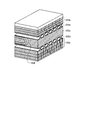
- FIG. 2 is a perspective view showing the structure of the gradient magnetic field coil according to the first embodiment.
- FIG. 3 is a view showing a stack of gradient magnetic field coils according to the first embodiment.
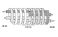
- FIG. 4 is a view for explaining the piping of the cooling pipe in the first embodiment.
- FIG. 5 is a diagram conceptually showing the piping of the cooling pipe in the first embodiment.
- FIG. 6 is a diagram conceptually showing the piping of the cooling pipe in Modification 1 of the first embodiment.
- FIG. 7 is a diagram conceptually showing the piping of the cooling pipe in Modification 2 of the first embodiment.
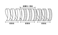
- FIG. 8 is a diagram conceptually showing the piping of the cooling pipe in the second embodiment.
- FIG. 9 is a diagram conceptually showing piping of a cooling pipe in a modification of the second embodiment.
- MRI Magnetic Resonance Imaging
- MRI Magnetic Resonance Imaging
- gradient magnetic field coil a magnetic resonance imaging apparatus
- the embodiments are not limited to the following embodiments.
- the contents described in each embodiment can be applied in the same manner to other embodiments in principle.
- FIG. 1 is a functional block diagram showing the configuration of the MRI apparatus 100 according to the first embodiment.
- the MRI apparatus 100 includes a static magnetic field magnet 101, a static magnetic field power supply 102, a gradient magnetic field coil 103, a gradient magnetic field power supply 104, an RF coil 105, a transmission unit 106, and a reception unit 107.
- the MRI apparatus 100 does not include a subject P (for example, a human body).
- the structure shown in FIG. 1 is only an example. Each unit may be appropriately integrated or separated.
- the static magnetic field magnet 101 is a magnet formed in the shape of a hollow substantially cylinder (including an ellipse), and generates a static magnetic field in a space inside the substantially cylinder.
- the static magnetic field magnet 101 is, for example, a superconducting magnet or the like, and is excited by receiving a current supplied from the static magnetic field power source 102.
- the static magnetic field power supply 102 supplies a current to the static magnetic field magnet 101.
- the static magnetic field magnet 101 may be a permanent magnet. In this case, the MRI apparatus 100 may not include the static magnetic field power source 102. In addition, the static magnetic field power source 102 may be provided separately from the MRI apparatus 100.
- the gradient magnetic field coil 103 is a coil disposed inside the static magnetic field magnet 101 and formed in a hollow, substantially cylindrical shape.
- the gradient coil 103 receives a current supplied from the gradient magnetic field power supply 104 and generates a gradient magnetic field.
- the gradient coil 103 will be described later in detail.
- the gradient magnetic field power supply 104 supplies a current to the gradient magnetic field coil 103.
- the RF coil 105 is disposed inside the gradient magnetic field coil 103 and receives a supply of RF pulses from the transmission unit 106 to generate a high-frequency magnetic field.
- the RF coil 105 also receives a magnetic resonance signal (hereinafter referred to as “MR (Magnetic Resonance) signal”) emitted from the subject P due to the influence of the high-frequency magnetic field, and outputs the received MR signal to the receiving unit 107.
- MR Magnetic Resonance
- the RF coil 105 described above is merely an example.
- the RF coil 105 may be configured by combining one or more of a coil having only a transmission function, a coil having only a reception function, or a coil having a transmission / reception function.
- the transmission unit 106 supplies the RF coil 105 with an RF pulse corresponding to the Larmor frequency determined by the type of target atom and the magnetic field strength.
- the receiving unit 107 detects the MR signal output from the RF coil 105, and generates MR data based on the detected MR signal. Specifically, the receiving unit 107 generates MR data by digitally converting the MR signal output from the RF coil 105.
- the receiving unit 107 also sends the generated MR data to the sequence control unit 120.
- the receiving unit 107 may be provided on the gantry device side including the static magnetic field magnet 101, the gradient magnetic field coil 103, and the like.
- the bed 108 includes a top plate on which the subject P is placed. In FIG. 1, only this top plate is shown for convenience of explanation. Normally, the bed 108 is installed such that the longitudinal axis of the substantially cylindrical center axis of the static magnetic field magnet 101 is parallel to the longitudinal axis. Further, the top plate is movable in the longitudinal direction and the vertical direction, and is inserted into a space inside a substantially cylinder inside the RF coil 105 with the subject P placed thereon. The space inside the substantially cylindrical shape is sometimes referred to as “bore” or the like.
- the sequence control unit 120 performs imaging of the subject P by driving the gradient magnetic field power supply 104, the transmission unit 106, and the reception unit 107 based on the sequence information transmitted from the computer 130.
- the sequence information is information defining a procedure for performing imaging.
- the sequence information includes the strength of the current supplied from the gradient magnetic field power supply 104 to the gradient magnetic field coil 103 and the timing of supplying the current, the strength of the RF pulse supplied from the transmitter 106 to the RF coil 105, the timing of applying the RF pulse, and reception.
- the timing at which the unit 107 detects the MR signal is defined.
- the sequence controller 120 is an integrated circuit such as an ASIC (Application Specific Integrated Circuit) or FPGA (Field Programmable Gate Array), or an electronic circuit such as a CPU (Central Processing Unit) or MPU (Micro Processing Unit).
- ASIC Application Specific Integrated Circuit
- FPGA Field Programmable Gate Array
- CPU Central Processing Unit
- MPU Micro Processing Unit
- the sequence controller 120 When the sequence controller 120 receives the MR data from the receiver 107 as a result of driving the gradient magnetic field power source 104, the transmitter 106, and the receiver 107 and imaging the subject P, the sequence controller 120 converts the received MR data to the computer 130. Forward to.
- the computer 130 performs overall control of the MRI apparatus 100. Further, the computer 130 generates MR images by performing reconstruction processing such as Fourier transform on the MR data transferred from the sequence control unit 120.
- the computer 130 includes a control unit, a storage unit, an input unit, and a display unit.
- the control unit is an integrated circuit such as an ASIC or FPGA, or an electronic circuit such as a CPU or MPU.
- the storage unit is a RAM (Random Access Memory), a semiconductor memory element such as a flash memory, a hard disk, an optical disk, or the like.
- the input unit is a pointing device such as a mouse or a trackball, a selection device such as a mode switch, or an input device such as a keyboard.
- the display unit is a display device such as a liquid crystal display.
- FIG. 2 is a perspective view showing the structure of the gradient coil 103 according to the first embodiment.
- the gradient magnetic field coil 103 is an ASGC (Actively Shielded Gradient Coil), a main coil 103 a that generates a gradient magnetic field, and a shield coil 103 b that generates a shield magnetic field that cancels the leakage magnetic field. And have.
- a main coil 103a, a cooling layer 103d in which a cooling pipe is piped, and a shim tray in which a shim tray is arranged are arranged in order from the inner side where the distance from the space inside the substantially cylindrical interior is short.
- the layer 103c, the cooling layer 103e to which the cooling pipe is piped, and the shield coil 103b are laminated.
- a plurality of (for example, 24) shim tray insertion guides 103f are formed in the shim layer 103c.
- the shim tray insertion guide 103f is typically a hole that penetrates the entire length of the gradient magnetic field coil 103 in the major axis direction, and is formed at equal intervals in the circumferential direction.
- Each of the shim trays (not shown) inserted into the shim tray insertion guide 103f has, for example, a plurality of (for example, 15) pockets in the longitudinal direction, and a predetermined pocket is used to correct the static magnetic field inhomogeneity.
- a predetermined number of iron shims are stored.
- FIG. 3 is a diagram illustrating the lamination of the gradient magnetic field coils 103 according to the first embodiment.
- cooling pipes are embedded in the cooling layer 103d and the cooling layer 103e spirally along a substantially cylindrical shape. That is, a cooling pipe on the main coil 103a side is embedded in the cooling layer 103d between the shim layer 103c and the main coil 103a. A cooling pipe on the shield coil 103b side is embedded in the cooling layer 103e between the shim layer 103c and the shield coil 103b.
- the main coil 103 a side cooling pipe and the shield coil 103 b side cooling pipe are both embedded in a spiral shape along the substantially cylindrical shape of the gradient magnetic field coil 103. The piping of these cooling pipes will be described in detail later.
- the MRI apparatus 100 further includes a cooling device having a heat exchanger and a circulation pump, and this cooling device supplies a coolant such as water to the cooling pipe.
- a cooling device having a heat exchanger and a circulation pump, and this cooling device supplies a coolant such as water to the cooling pipe.
- a cooling pipe is provided in an intermediate layer of the gradient magnetic field coil 103 so as to sandwich the shim layer 103c so as to cool the iron shim arranged in the shim layer 103c and the entire gradient magnetic field coil 103. It is plumbed.
- the heat generated by the main coil 103a is blocked by the cooling pipe of the cooling layer 103d, so that it is difficult for the heat to be transmitted to the iron shim disposed in the shim layer 103c.
- the heat generated by the shield coil 103b is blocked by the cooling pipe of the cooling layer 103e, so that it is difficult for the heat to be transmitted to the iron shim disposed in the shim layer 103c.
- FIG. 4 is a view for explaining the piping of the cooling pipe in the first embodiment.
- the cooling pipe on the main coil 103a side and the cooling pipe on the shield coil 103b side are piped in the same configuration. For this reason, in the following description, the cooling pipe on the shield coil 103b side will be described as an example.
- FIG. 4 shows a perspective view of the cooling pipe piping on the shield coil 103b side.
- first end one end in the major axis direction of the gradient magnetic field coil 103 and the end on the near side in FIG. 4
- second end one end in the back side in FIG. 4
- first end one end in the major axis direction of the gradient magnetic field coil 103 and the end on the near side in FIG. 4
- second end the other end and the end on the back side in FIG.
- the cooling pipe is piped so as to preferentially cool the vicinity of the uniform area where the uniformity of the static magnetic field is maintained.
- the uniform region is also referred to as “image-capable region” or the like, and is a region unique to the MRI apparatus 100 that is determined when a static magnetic field magnet is designed.
- the uniform region is provided near the center between the first end and the second end, that is, near the center of the gradient magnetic field coil 103 in the major axis (z-axis) direction.
- the x-axis direction is 50 cm ⁇ y-axis direction. It is expressed by a cylindrical region such as 50 cm ⁇ 45 cm in the z-axis direction. That is, the cooling pipe is piped so as to preferentially cool the vicinity of the center in the long axis direction of the gradient coil 103.
- the cooling pipe is divided into two cooling pipes as shown in FIG.
- One system is a first cooling pipe 10 that goes straight from the first end toward the second end, is bent in the vicinity of the center in the major axis direction, and is then spirally piped back to the first end.
- the first cooling pipe 10 is composed of, for example, three parallel cooling pipes, and a manifold for branching or joining a refrigerant (for example, water) is provided on each of the inlet side and the outlet side. It is done.
- a refrigerant for example, water
- the other system is a second cooling pipe 20 that goes straight from the second end toward the first end, bends in the vicinity of the center in the major axis direction, and then spirally pipes back to the second end. is there.
- the second cooling pipe 20 is also constituted by, for example, three parallel cooling pipes, and a manifold is provided on each of the inlet side and the outlet side. In FIG. 4, for convenience of explanation, three parallel cooling pipes are partially omitted.
- each system cooling pipe is configured by three parallel cooling pipes will be described, but the embodiment is not limited thereto. It may be composed of two or four or more cooling pipes, or may be composed of one cooling pipe.
- cooling water supplied from a cooling device is first branched by the inlet manifold 10a in the first cooling pipe 10 and flows into each of the three cooling pipes.
- the cooling water that has flowed into the three cooling pipes is transported to the vicinity of the center of the gradient magnetic field coil 103 in the long axis direction at the shortest distance, and subsequently injected from the vicinity of the center, the gradient magnetic field coil toward the first end. It flows spirally along the shape of the substantially cylindrical shape 103. Thereafter, the cooling water branched into the three cooling pipes is merged again at the outlet manifold 10b and returned to the cooling device.
- the cooling water supplied from the cooling device is first branched by the inlet manifold 20a and flows into each of the three cooling pipes.
- the cooling water that has flowed into the three cooling pipes is transported to the vicinity of the center of the gradient magnetic field coil 103 in the long axis direction at the shortest distance, and subsequently injected from the vicinity of the center, the gradient magnetic field coil toward the second end. It flows spirally along the shape of the substantially cylindrical shape 103. Thereafter, the cooling water branched into the three cooling pipes is merged again at the outlet manifold 20b and returned to the cooling device.
- the first cooling pipe 10 or the second cooling pipe 20 when the first cooling pipe 10 or the second cooling pipe 20 is a conductive metal, it is connected to each manifold via a tube formed of an insulating material.
- a tube formed of an insulating material between each cooling pipe and each manifold, it is possible to prevent an electrical closed loop from being formed by each cooling pipe.
- a manifold formed of a metal such as brass
- a manifold formed of an insulating material such as Teflon (registered trademark) or PET (polyethylene terephthalate) may be used. In this case, it is not necessary to go through a tube formed of an insulating material.
- the cooling pipe that goes straight from the first end to the vicinity of the center in the long axis direction or from the second end to the vicinity of the center in the long axis direction is, for example, a region and a region of the shim tray insertion guide 103f. It is piped so that it may be embedded in the groove part formed between.
- FIG. 5 is a diagram conceptually showing the piping of the cooling pipe in the first embodiment, and corresponds to the piping shown in FIG.
- three parallel cooling pipes are indicated by dotted lines or solid lines.
- the dotted line corresponds to the first cooling pipe 10
- the solid line corresponds to the second cooling pipe 20.
- a spiral pattern expressed by two types of patterns is expressed in a simplified manner or in order to clearly show the piping path of three parallel cooling pipes that are piped in a spiral shape. Is.
- the number of turns (the number of turns) and the interval are merely for the convenience of conceptually showing the piping of the cooling pipe.
- the number of turns is arbitrarily designed in accordance with the actual gradient coil 103, and the interval may be piped so as to be in contact with each other as shown in FIGS.
- the piping may be provided with a certain width.
- interval may be provided between three piping, and may be provided between the groups of three piping.
- a diagram conceptually showing the piping of the cooling pipe is used, but it has the same meaning as described above.
- the first cooling pipe 10 goes straight from the first end toward the second end, bends in the vicinity of the center in the major axis direction, and then the first end. It is piped in a spiral shape so as to return to.
- the second cooling pipe 20 goes straight from the second end toward the first end, is bent in the vicinity of the center in the long axis direction, and is then spirally piped so as to return to the second end.
- the start position of the pipe in the vicinity of the center in the long axis direction of the first cooling pipe 10 and the second cooling pipe 20 is substantially the same position on the circumference of the gradient magnetic field coil 103. is there.
- the cooling water supplied from the cooling device and having a low temperature and a stable temperature is first transported from both ends of the first end and the second end to the vicinity of the center in the long axis direction at the shortest distance. Since cooling is started, the vicinity of the center is always cooled with cooling water having a stable temperature. As a result, the temperature increase of the iron shim disposed near the center in the major axis direction of the gradient coil 103 is suppressed, and a constant temperature can be maintained. Then, an increase in the center frequency of the imaging region, which is positioned near the center in the long axis direction, can be suppressed, so that adverse effects on image quality can be reduced.
- the iron shim arranged near the end of the gradient coil 103 can be warmed by warm water whose temperature has risen, but the iron shim arranged in this position has a center frequency when the temperature rises. Since it works in the direction of lowering, it eventually plays the role of suppressing the rise of the center frequency.
- the cooling pipe is piped so that the cooling water having a low temperature is carried near the center in the long axis direction, the vicinity of the so-called uniform region is preferentially cooled. As a result, the relative temperature rise near the imaging region can be suppressed, and the image quality can be improved.
- FIG. 6 is a diagram conceptually illustrating the piping of the cooling pipe in the first modification of the first embodiment.
- the first cooling pipe 10 (indicated by a dotted line in FIG. 6) goes straight from the first end toward the second end, bends near the center in the long axis direction, and then returns to the first end.
- the pipe is piped so as to be bent again at the first end and go straight to the second end.
- the second cooling pipe 20 (shown by a solid line in FIG. 6) is arranged in a spiral shape so as to go straight from the second end toward the first end, bend near the center in the long axis direction, and return to the second end.
- the pipe is bent so as to be bent again at the second end and go straight to the first end.
- the start position of the pipe in the vicinity of the center in the long axis direction of the first cooling pipe 10 and the second cooling pipe 20 is substantially the same position on the circumference of the gradient magnetic field coil 103. is there.
- the difference from the pipe conceptually shown in FIG. 5 is that the outlet of the cooling pipe after being spirally wound is provided on the same side as the inlet or on the opposite side.
- the first cooling pipe 10 has the first end side as an inlet (IN) and the second end side as an outlet (OUT).
- the second cooling pipe 20 has a second end side as an inlet (IN) and a first end side as an outlet (OUT). According to such a pipe, it is not necessary to bend the cooling pipe at the end portion in the long axis direction, so that the cooling pipe is spirally wound to the end portion in the long axis direction as compared with the pipe in FIG. There is an effect that can be.
- FIG. 7 is a diagram conceptually showing the piping of the cooling pipe in Modification 2 of the first embodiment.
- the starting position of the piping in the vicinity of the center in the major axis direction of the first cooling pipe 10 and the second cooling pipe 20 is a position that is substantially opposite on the circumference (on the opposite side for about half a circle). is there. That is, in the piping shown in FIG. 7, the first cooling pipe 10 (indicated by a dotted line in FIG. 7) begins to spirally from the back side in the circumferential direction of the gradient magnetic field coil 103, but the second cooling pipe 20 (FIG.
- FIG. 7 like the piping conceptually shown in FIG. 5, the outlet of the cooling pipe after being spirally wound is provided on the same side as the inlet, but the embodiment is limited to this. is not. Similarly to the pipe conceptually shown in FIG. 6, the outlet of the cooling pipe after being spirally wound may be provided on the side opposite to the inlet.
- the cooling pipe is piped so as to preferentially cool the vicinity of the uniform region where the uniformity of the static magnetic field is maintained. But in 2nd Embodiment, it does not adjust the starting position of piping wound spirally, but it adjusts with piping density.
- This pipe density is the density of the number of turns within a predetermined range. When compared within the same range, the higher the number of turns, the higher the pipe density, and the lower the number of turns, the lower the pipe density.
- FIG. 8 is a diagram conceptually showing the piping of the cooling pipe in the second embodiment.
- the cooling pipe in the second embodiment, is configured such that the pipe density near the center in the long axis direction of the gradient magnetic field coil 103 is higher than the pipe density near the end in the long axis direction.
- the cooling pipe includes a first cooling pipe 10 (represented by a white pattern in FIG. 8) that is spirally piped on the first end side, and a second end side.
- the second cooling pipes 20 (represented by dot patterns in FIG. 8) that are piped in a spiral manner are piped by being alternately combined near the center in the long axis direction.
- first cooling pipes 10 and second cooling pipes 20 may be alternately combined one by one, or a plurality of (for example, three) may be alternately staggered. May be combined.
- the first cooling pipe 10 and the second cooling pipe 20 are overlapped to increase the pipe density in the vicinity of the uniform area. Cool around the area strongly.
- the vicinity of the end portion in the long axis direction for example, it is intentionally wound “sparsely” to reduce the number of turns (number of turns) of the cooling pipe, thereby reducing the pipe density.
- the vicinity of the center in the long axis direction is strongly cooled and the vicinity of the uniform area is preferentially cooled, so that the relative temperature rise near the imaging area can be suppressed and the image quality can be improved. Further, the vicinity of the end portion in the major axis direction is not cooled so much, and as a result of being heated in some cases, it works in the direction of lowering the center frequency and eventually suppresses the rise of the center frequency.
- FIG. 9 is a diagram conceptually showing cooling pipes in a modification of the second embodiment.
- the cooling pipe is a first cooling pipe 10 that is spirally piped on the first end side (represented by a white pattern in FIG. 9). Piping is performed by changing the pipe density so that the pipe density near the center is higher than the pipe density at the end.
- the second cooling pipe 20 that is spirally piped on the second end side (represented by a dot pattern in FIG. 9)
- the pipe density near the center is higher than the pipe density at the end.
- the piping density is changed and piping is performed.
- the vicinity of the center in the major axis direction is strongly cooled and the vicinity of the uniform area is preferentially cooled, so that the relative temperature rise near the imaging area is suppressed and the image quality is improved. Can do. Further, the vicinity of the end portion in the major axis direction is not cooled so much, and as a result of being heated in some cases, it works in the direction of lowering the center frequency and eventually suppresses the rise of the center frequency.
- FIG. 8 and 9 conceptually show how the pipe density is changed depending on the position of the gradient coil 103 in the major axis direction, but the embodiment is limited to the examples of FIG. 8 and FIG. For example, it may be a change in which the density gradually changes to “sparse” toward the end in the long axis direction. Further, whether to start winding from the end portion or to start winding from the vicinity of the center in the long axis direction as described in the first embodiment can be arbitrarily selected. In addition, it is possible to arbitrarily select whether the outlet of the cooling pipe after being spirally wound is provided on the same side as the inlet or on the opposite side.
- the starting position of piping is made into the substantially same position on a circumference, or a substantially opposite position. That is, as long as the winding density is adjusted according to the position of the gradient magnetic field coil 103 in the long axis direction, the pipe density can be arbitrarily changed according to the operation mode or the like.
- the magnetic resonance imaging apparatus and the gradient magnetic field coil of at least one embodiment described above it is possible to suppress the relative temperature rise near the uniform region and improve the image quality.
Landscapes
- Physics & Mathematics (AREA)
- Condensed Matter Physics & Semiconductors (AREA)
- General Physics & Mathematics (AREA)
- Health & Medical Sciences (AREA)
- Life Sciences & Earth Sciences (AREA)
- Nuclear Medicine, Radiotherapy & Molecular Imaging (AREA)
- Electromagnetism (AREA)
- Magnetic Resonance Imaging Apparatus (AREA)
- Pathology (AREA)
- Molecular Biology (AREA)
- Radiology & Medical Imaging (AREA)
- Engineering & Computer Science (AREA)
- Biomedical Technology (AREA)
- Heart & Thoracic Surgery (AREA)
- Medical Informatics (AREA)
- Biophysics (AREA)
- Surgery (AREA)
- Animal Behavior & Ethology (AREA)
- General Health & Medical Sciences (AREA)
- Public Health (AREA)
- Veterinary Medicine (AREA)
- High Energy & Nuclear Physics (AREA)
Abstract
実施形態に係る磁気共鳴イメージング装置(100)は、静磁場を発生する静磁場磁石(101)と、冷却管が配管された傾斜磁場コイル(103)とを備える。また、前記冷却管は、前記静磁場の均一性が保たれる均一領域付近を優先的に冷却するように配管される。
Description
本発明の実施形態は、磁気共鳴イメージング装置及び傾斜磁場コイルに関する。
磁気共鳴イメージングは、静磁場中に置かれた被検体の原子核スピンを、そのラーモア(Larmor)周波数のRF(Radio Frequency)パルスで磁気的に励起し、励起に伴い発生する磁気共鳴信号のデータから画像を生成する撮像法である。
この磁気共鳴イメージングにおいては、高分解能撮像時や高速撮像時、傾斜磁場コイル内に配置されている金属シム(例えば、鉄シム)の温度が上昇する傾向にある。鉄シムは、本来、静磁場の不均一を補正するために配置されるものであるが、鉄シムの温度が上昇すると、磁化率が変化する結果、静磁場の中心周波数に影響が及ぶことがある。具体的には、傾斜磁場コイルの長軸方向中央付近に配置された鉄シムは、温度が上昇すると、中心周波数を上げる方向に働き、長軸方向端部付近に配置された鉄シムは、温度が上昇すると、中心周波数を下げる方向に働く。
イメージング領域は長軸方向中央付近であるので、この付近に配置された鉄シムの温度上昇の影響は特に大きく、脂肪抑制の劣化や、EPI(Echo Planar Imaging)におけるN/2アーチファクト、画像の歪等、画質劣化を引き起こすおそれがある。しかしながら、従来の傾斜磁場コイルにおける冷却管の配管では、依然として長軸方向中央付近に配置された鉄シムの温度上昇を抑えることができない。
本発明が解決しようとする課題は、均一領域付近の相対的な温度上昇を抑え、画質を向上することができる磁気共鳴イメージング装置及び傾斜磁場コイルを提供することである。
実施形態に係る磁気共鳴イメージング装置は、静磁場を発生する静磁場磁石と、冷却管が配管された傾斜磁場コイルとを備える。前記冷却管は、前記静磁場の均一性が保たれる均一領域付近を優先的に冷却するように配管される。
以下、図面を参照しながら、実施形態に係る磁気共鳴イメージング装置(以下、適宜「MRI(Magnetic Resonance Imaging)装置」)及び傾斜磁場コイルを説明する。なお、実施形態は、以下の実施形態に限られるものではない。また、各実施形態において説明する内容は、原則として、他の実施形態においても同様に適用することができる。
(第1の実施形態)
図1は、第1の実施形態に係るMRI装置100の構成を示す機能ブロック図である。図1に示すように、MRI装置100は、静磁場磁石101と、静磁場電源102と、傾斜磁場コイル103と、傾斜磁場電源104と、RFコイル105と、送信部106と、受信部107と、寝台108と、シーケンス制御部120と、計算機130とを備える。なお、MRI装置100に、被検体P(例えば、人体)は含まれない。また、図1に示す構成は一例に過ぎない。各部は、適宜統合若しくは分離して構成されてもよい。
図1は、第1の実施形態に係るMRI装置100の構成を示す機能ブロック図である。図1に示すように、MRI装置100は、静磁場磁石101と、静磁場電源102と、傾斜磁場コイル103と、傾斜磁場電源104と、RFコイル105と、送信部106と、受信部107と、寝台108と、シーケンス制御部120と、計算機130とを備える。なお、MRI装置100に、被検体P(例えば、人体)は含まれない。また、図1に示す構成は一例に過ぎない。各部は、適宜統合若しくは分離して構成されてもよい。
静磁場磁石101は、中空の略円筒(楕円を含む)の形状に形成された磁石であり、略円筒内部の空間に、静磁場を発生する。静磁場磁石101は、例えば、超伝導磁石等であり、静磁場電源102から電流の供給を受けて励磁する。静磁場電源102は、静磁場磁石101に電流を供給する。なお、静磁場磁石101は、永久磁石でもよく、この場合、MRI装置100は、静磁場電源102を備えなくてもよい。また、静磁場電源102は、MRI装置100とは別に備えられてもよい。
傾斜磁場コイル103は、静磁場磁石101の内側に配置され、中空の略円筒の形状に形成されたコイルである。傾斜磁場コイル103は、傾斜磁場電源104から電流の供給を受けて傾斜磁場を発生する。なお、傾斜磁場コイル103については、後に詳述する。傾斜磁場電源104は、傾斜磁場コイル103に電流を供給する。
RFコイル105は、傾斜磁場コイル103の内側に配置され、送信部106からRFパルスの供給を受けて高周波磁場を発生する。また、RFコイル105は、高周波磁場の影響によって被検体Pから発せられる磁気共鳴信号(以下、適宜「MR(Magnetic Resonance)信号」)を受信し、受信したMR信号を受信部107に出力する。
なお、上述したRFコイル105は一例に過ぎない。RFコイル105は、送信機能のみを備えたコイル、受信機能のみを備えたコイル、若しくは送受信機能を備えたコイルのうち、1つ若しくは複数を組み合わせることによって構成されればよい。
送信部106は、対象とする原子の種類及び磁場強度で定まるラーモア周波数に対応するRFパルスをRFコイル105に供給する。受信部107は、RFコイル105から出力されるMR信号を検出し、検出したMR信号に基づいてMRデータを生成する。具体的には、受信部107は、RFコイル105から出力されるMR信号をデジタル変換することによってMRデータを生成する。また、受信部107は、生成したMRデータをシーケンス制御部120に送る。なお、受信部107は、静磁場磁石101や、傾斜磁場コイル103等を備える架台装置側に備えられてもよい。
寝台108は、被検体Pが載置される天板を備える。図1においては、説明の便宜上、この天板のみを図示する。通常、寝台108は、静磁場磁石101の略円筒の中心軸と長手方向が平行になるように設置される。また、天板は、長手方向及び上下方向に移動可能であり、被検体Pが載置された状態で、RFコイル105の内側の略円筒内部の空間に挿入される。なお、この略円筒内部の空間を「ボア」等と称する場合がある。
シーケンス制御部120は、計算機130から送信されるシーケンス情報に基づいて、傾斜磁場電源104、送信部106、及び受信部107を駆動することによって、被検体Pの撮像を行う。ここで、シーケンス情報は、撮像を行う手順を定義した情報である。シーケンス情報には、傾斜磁場電源104が傾斜磁場コイル103に供給する電流の強さや電流を供給するタイミング、送信部106がRFコイル105に供給するRFパルスの強さやRFパルスを印加するタイミング、受信部107がMR信号を検出するタイミング等が定義される。
例えば、シーケンス制御部120は、ASIC(Application Specific Integrated Circuit)、FPGA(Field Programmable Gate Array)等の集積回路、CPU(Central Processing Unit)、MPU(Micro Processing Unit)等の電子回路である。
なお、シーケンス制御部120は、傾斜磁場電源104、送信部106、及び受信部107を駆動して被検体Pを撮像した結果、受信部107からMRデータを受信すると、受信したMRデータを計算機130に転送する。
計算機130は、MRI装置100の全体制御を行う。また、計算機130は、シーケンス制御部120から転送されたMRデータに、フーリエ変換等の再構成処理を施すことで、MR画像の生成等を行う。例えば、計算機130は、制御部、記憶部、入力部、表示部を備える。制御部は、ASIC、FPGA等の集積回路、CPU、MPU等の電子回路である。記憶部は、RAM(Random Access Memory)、フラッシュメモリ等の半導体メモリ素子、ハードディスク、光ディスク等である。入力部は、マウスやトラックボール等のポインティングデバイス、モード切替スイッチ等の選択デバイス、あるいはキーボード等の入力デバイスである。表示部は、液晶表示器等の表示デバイスである。
図2は、第1の実施形態に係る傾斜磁場コイル103の構造を示す斜視図である。ここで、第1の実施形態において、傾斜磁場コイル103は、ASGC(Actively Shielded Gradient Coil)であり、傾斜磁場を発生するメインコイル103aと、漏洩磁場を打ち消すシールド用の磁場を発生するシールドコイル103bとを有する。図2に示すように、傾斜磁場コイル103においては、略円筒内部の空間からの距離が近い内側から順に、メインコイル103aと、冷却管が配管される冷却層103dと、シムトレイが配置されるシム層103cと、冷却管が配管される冷却層103eと、シールドコイル103bとが、積層される。
シム層103cには、複数本分(例えば24本分)のシムトレイ挿入ガイド103fが形成される。シムトレイ挿入ガイド103fは、典型的には、図2に示すように、傾斜磁場コイル103の長軸方向全長に亘って貫通する穴であり、円周方向に等間隔に形成される。シムトレイ挿入ガイド103fに挿入されるシムトレイ(図示を省略)それぞれは、例えば、長手方向に複数(例えば15個)のポケットを有し、静磁場の不均一性を補正するために、所定のポケットに所定の枚数の鉄シムが収納される。
図3は、第1の実施形態に係る傾斜磁場コイル103の積層を示す図である。図3に示すように、冷却層103d及び冷却層103eには、略円筒の形状に沿って螺旋状に冷却管が埋設される。即ち、シム層103cとメインコイル103aとの間の冷却層103dには、メインコイル103a側の冷却管が埋設される。また、シム層103cとシールドコイル103bとの間の冷却層103eには、シールドコイル103b側の冷却管が埋設される。メインコイル103a側の冷却管及びシールドコイル103b側の冷却管は、いずれも傾斜磁場コイル103の略円筒の形状に沿って螺旋状に埋設される。なお、これらの冷却管の配管については、後に詳述する。
なお、図1において図示を省略したが、第1の実施形態に係るMRI装置100は、熱交換器や循環ポンプを有する冷却装置を更に備え、この冷却装置が、冷却管に水等の冷媒を循環させることで、シム層103cに配置された鉄シムや傾斜磁場コイル103全体を冷却する。
このように、傾斜磁場コイル103では、シム層103cに配置された鉄シム、及び、傾斜磁場コイル103全体を冷却すべく、シム層103cを挟むように傾斜磁場コイル103の中間層に冷却管が配管される。例えば、メインコイル103aによって発生した熱は、冷却層103dの冷却管によって遮られることで、シム層103cに配置された鉄シムに伝わりにくくなる。また、例えば、シールドコイル103bによって発生した熱は、冷却層103eの冷却管によって遮られることで、シム層103cに配置された鉄シムに伝わりにくくなる。
次に、図4は、第1の実施形態における冷却管の配管を説明するための図である。なお、第1の実施形態において、メインコイル103a側の冷却管とシールドコイル103b側の冷却管とは同様の構成で配管される。このため、以下では、シールドコイル103b側の冷却管を例に挙げて説明する。
図4では、シールドコイル103b側の冷却管の配管の斜視図を示す。また、説明の便宜上、傾斜磁場コイル103の長軸方向の一端であって図4において手前側の端部を「第1端」と称し、他端であって図4において奥側の端部を「第2端」と称する。
第1の実施形態において、冷却管は、静磁場の均一性が保たれる均一領域付近を優先的に冷却するように配管される。ここで、均一領域とは、「撮像可能領域」等とも称され、静磁場磁石を設計する際に定まる、MRI装置100固有の領域である。また、均一領域は、第1端と第2端との間の中央付近、即ち、傾斜磁場コイル103の長軸(z軸)方向中央付近に設けられ、例えば、x軸方向50cm×y軸方向50cm×z軸方向45cm等の円筒形状の領域で表現される。即ち、冷却管は、傾斜磁場コイル103の長軸方向中央付近を優先的に冷却するように配管される。
具体的には、第1の実施形態において、冷却管は、図4に示すように、2系統の冷却管に分けて配管される。1系統は、第1端から第2端に向かって直進し、長軸方向中央付近で屈曲してから第1端に戻るように螺旋状に配管される、第1冷却管10である。この第1冷却管10は、図4に示すように、例えば3本の並列の冷却管で構成され、入口側及び出口側のそれぞれに、冷媒(例えば、水)を分岐若しくは合流するマニホールドが設けられる。
また、もう1系統は、第2端から第1端に向かって直進し、長軸方向中央付近で屈曲してから第2端に戻るように螺旋状に配管される、第2冷却管20である。この第2冷却管20も、第1冷却管10と同様、図4に示すように、例えば3本の並列の冷却管で構成され、入口側及び出口側のそれぞれにマニホールドが設けられる。なお、図4においては、説明の便宜上、3本の並列の冷却管を一部省略して示す。また、第1の実施形態においては、各系統の冷却管が、それぞれ3本の並列の冷却管で構成される例を説明するが、実施形態はこれに限られるものではない。2本や4本以上の冷却管で構成されてもよいし、あるいは、1本の冷却管で構成されてもよい。
かかる冷却管の配管において、冷却装置(図示を省略)から供給された冷却水は、第1冷却管10では、まず入口マニホールド10aで分岐され、3本の冷却管それぞれに流入する。3本の冷却管に流入した冷却水は、傾斜磁場コイル103の長軸方向中央付近に、最短距離で運ばれ、続いて中央付近から注水されると、第1端に向かって、傾斜磁場コイル103の略円筒の形状に沿って螺旋状に流れていく。その後、3本の冷却管に分岐していた冷却水は、出口マニホールド10bで再び合流されて、冷却装置へと戻される。
同様に、冷却装置から供給された冷却水は、第2冷却管20では、まず入口マニホールド20aで分岐され、3本の冷却管それぞれに流入する。3本の冷却管に流入した冷却水は、傾斜磁場コイル103の長軸方向中央付近に、最短距離で運ばれ、続いて中央付近から注水されると、第2端に向かって、傾斜磁場コイル103の略円筒の形状に沿って螺旋状に流れていく。その後、3本の冷却管に分岐していた冷却水は、出口マニホールド20bで再び合流されて、冷却装置へと戻される。
なお、第1の実施形態において、第1冷却管10や第2冷却管20が導電性金属の場合は、絶縁材で形成されたチューブを介して、各マニホールドに接続される。このように、各冷却管と各マニホールドとの間に絶縁材で形成されたチューブを設けることで、各冷却管によって電気的な閉ループが形成されることを防ぐことができる。なお、真鍮等の金属で形成されたマニホールドに替えて、テフロン(登録商標)や、PET(ポリエチレン・テレフタレート)等の絶縁材で形成されたマニホールドを用いてもよい。この場合は絶縁材で形成されたチューブを介さなくてよい。また、第1の実施形態において、第1端から長軸方向中央付近へ、若しくは、第2端から長軸方向中央付近へと直進する冷却管は、例えば、シムトレイ挿入ガイド103fの領域と領域との間に形成された溝部に埋設されるように配管される。
図5は、第1の実施形態における冷却管の配管を概念的に示す図であり、図4に示した配管に対応する。ここで、図5においては、3本の並列の冷却管を、点線、若しくは実線で示す。点線は、第1冷却管10に対応し、実線は、第2冷却管20に対応する。また、図5において、2種類のパターンで表現する螺旋状の模様は、螺旋状に配管される3本の並列の冷却管を、簡略化して、あるいは、その配管経路を明示するために表現するものである。その巻き数(ターン数)や間隔は、冷却管の配管を概念的に示す便宜上のものに過ぎない。即ち、巻き数は、実際の傾斜磁場コイル103に合わせて任意に設計されるものであるし、間隔も、図3や図4に示したように、相互に接するように配管してもよいし、ある程度の幅を空けて配管してもよい。また、この間隔は、3本の配管同士の間に設けてもよいし、3本の配管の組同士の間に設けてもよい。なお、以降の説明においても、冷却管の配管を概念的に示す図を用いることとするが、上述と同様の意味合いを有するものである。
さて、図5に示すように、第1冷却管10(図5において点線で示す)は、第1端から第2端に向かって直進し、長軸方向中央付近で屈曲してから第1端に戻るように螺旋状に配管される。第2冷却管20(図5において実線で示す)は、第2端から第1端に向かって直進し、長軸方向中央付近で屈曲してから第2端に戻るように螺旋状に配管される。なお、図5に示す配管では、第1冷却管10と、第2冷却管20との長軸方向中央付近における配管の開始位置が、傾斜磁場コイル103の円周上で、略同一の位置である。
このように、冷却装置から供給された、温度が低く、且つ、温度が安定した冷却水は、第1端及び第2端の両端からまず長軸方向中央付近に最短距離で運ばれ、ここから冷却が開始されるので、中央付近は、常に、冷たく、安定した温度の冷却水で冷却される。この結果、傾斜磁場コイル103の長軸方向中央付近に配置された鉄シムの温度上昇は抑えられ、一定の温度を保つことが可能になる。すると、長軸方向中央付近に位置付けられる、イメージング領域の中心周波数の上昇も抑えられるので、画質への悪影響を低減することができる。
更に、傾斜磁場コイル103の端部付近に配置された鉄シムは、温度が上昇した温かい水によって温められることになり得るが、この位置に配置された鉄シムは、温度が上昇すると中心周波数を下げる方向に働くので、結局、中心周波数の上昇を抑える役割を担う。
上述してきたように、第1の実施形態によれば、長軸方向中央付近に温度の低い冷却水が運ばれるように冷却管が配管されるので、いわゆる均一領域付近が優先的に冷却される結果、イメージング領域付近の相対的な温度上昇を抑え、画質を向上することができる。
(第1の実施形態の変形例1)
図6は、第1の実施形態の変形例1における冷却管の配管を概念的に示す図である。図6に示すように、第1冷却管10(図6において点線で示す)は、第1端から第2端に向かって直進し、長軸方向中央付近で屈曲してから第1端に戻るように螺旋状に配管され、第1端で再び屈曲して第2端に直進するように配管される。第2冷却管20(図6において実線で示す)は、第2端から第1端に向かって直進し、長軸方向中央付近で屈曲してから第2端に戻るように螺旋状に配管され、第2端で再び屈曲して第1端に直進するように配管される。なお、図6に示す配管では、第1冷却管10と、第2冷却管20との長軸方向中央付近における配管の開始位置が、傾斜磁場コイル103の円周上で、略同一の位置である。
図6は、第1の実施形態の変形例1における冷却管の配管を概念的に示す図である。図6に示すように、第1冷却管10(図6において点線で示す)は、第1端から第2端に向かって直進し、長軸方向中央付近で屈曲してから第1端に戻るように螺旋状に配管され、第1端で再び屈曲して第2端に直進するように配管される。第2冷却管20(図6において実線で示す)は、第2端から第1端に向かって直進し、長軸方向中央付近で屈曲してから第2端に戻るように螺旋状に配管され、第2端で再び屈曲して第1端に直進するように配管される。なお、図6に示す配管では、第1冷却管10と、第2冷却管20との長軸方向中央付近における配管の開始位置が、傾斜磁場コイル103の円周上で、略同一の位置である。
図5に概念的に示す配管との違いは、螺旋状に巻き終わった後の冷却管の出口を、入口と同じ側に設けるか、あるいは反対側に設けるかという点である。図6に概念的に示す配管の例では、第1冷却管10は、第1端側を入口(IN)としながら、第2端側を出口(OUT)とする。同様に、第2冷却管20は、第2端側を入口(IN)としながら、第1端側を出口(OUT)とする。このような配管によれば、長軸方向の端部で冷却管を屈曲させる必要がなくなるので、図5の配管に比較して、長軸方向のより端部まで、冷却管を螺旋状に巻くことができるという効果がある。
(第1の実施形態の変形例2)
図7は、第1の実施形態の変形例2における冷却管の配管を概念的に示す図である。図7に示す配管では、第1冷却管10と、第2冷却管20との長軸方向中央付近における配管の開始位置が、円周上で略反対(約半周分、反対側)の位置である。即ち、図7に示す配管では、第1冷却管10(図7において点線で示す)は、傾斜磁場コイル103の円周方向の奥側から螺旋状に巻き始めるが、第2冷却管20(図7において実線で示す)は、約半周分ずれた、円周方向の手前側から螺旋状に巻き始める。このように巻き始めの円周上の位置を離すことで、長軸方向中央付近に配置された鉄シムを、2つの方向から同時に冷却することができ、より均一に冷却することができるという効果がある。
図7は、第1の実施形態の変形例2における冷却管の配管を概念的に示す図である。図7に示す配管では、第1冷却管10と、第2冷却管20との長軸方向中央付近における配管の開始位置が、円周上で略反対(約半周分、反対側)の位置である。即ち、図7に示す配管では、第1冷却管10(図7において点線で示す)は、傾斜磁場コイル103の円周方向の奥側から螺旋状に巻き始めるが、第2冷却管20(図7において実線で示す)は、約半周分ずれた、円周方向の手前側から螺旋状に巻き始める。このように巻き始めの円周上の位置を離すことで、長軸方向中央付近に配置された鉄シムを、2つの方向から同時に冷却することができ、より均一に冷却することができるという効果がある。
なお、図7においては、図5に概念的に示した配管と同様、螺旋状に巻き終わった後の冷却管の出口を入口と同じ側に設けているが、実施形態はこれに限られるものではない。図6に概念的に示した配管と同様、螺旋状に巻き終わった後の冷却管の出口を入口と反対側に設けてもよい。
(第2の実施形態)
続いて、第2の実施形態を説明する。第2の実施形態においても、第1の実施形態と同様、冷却管は、静磁場の均一性が保たれる均一領域付近を優先的に冷却するように配管される。もっとも、第2の実施形態においては、螺旋状に巻く配管の開始位置を調整するのではなく、配管密度で調整する。この配管密度とは、即ち、所定範囲内における巻き数の密集度合いである。同一の範囲内で比較した場合に、巻き数が多ければ多いほど、配管密度は高く、巻き数が少なければ少ないほど、配管密度は低くなる。
続いて、第2の実施形態を説明する。第2の実施形態においても、第1の実施形態と同様、冷却管は、静磁場の均一性が保たれる均一領域付近を優先的に冷却するように配管される。もっとも、第2の実施形態においては、螺旋状に巻く配管の開始位置を調整するのではなく、配管密度で調整する。この配管密度とは、即ち、所定範囲内における巻き数の密集度合いである。同一の範囲内で比較した場合に、巻き数が多ければ多いほど、配管密度は高く、巻き数が少なければ少ないほど、配管密度は低くなる。
図8は、第2の実施形態における冷却管の配管を概念的に示す図である。図8に示すように、第2の実施形態において、冷却管は、傾斜磁場コイル103の長軸方向中央付近の配管密度が、長軸方向端部付近の配管密度に比較して高くなるように、配管される。より具体的には、第2の実施形態において、冷却管は、第1端側で螺旋状に配管される第1冷却管10(図8において白抜きのパターンで表現)と、第2端側で螺旋状に配管される第2冷却管20(図8においてドットのパターンで表現)とが、長軸方向の中央付近で互い違いに組み合わされて配管される。
なお、図8に概念的に示す配管は、第1冷却管10及び第2冷却管20が、それぞれ、何本ずつ並列で配管されるかについて、限定するものではない。また、長軸方向中央付近で互い違いに組み合わされる場合も、第1冷却管10と第2冷却管20とが1本ずつ互い違いに組み合わされてもよいし、複数本(例えば、3本)ずつ互い違いに組み合わされてもよい。
要は、第2の実施形態においては、いわば均一領域付近においては、第1冷却管10と第2冷却管20とをオーバーラップさせて配管することで、均一領域付近の配管密度を高め、均一領域付近を強力に冷却する。一方で、長軸方向端部付近では、例えば、意図的に「疎」に巻いて冷却管の巻き数(ターン数)を減らし、配管密度を下げる。
この結果、長軸方向中央付近が強力に冷却され、均一領域付近が優先的に冷却されるので、イメージング領域付近の相対的な温度上昇を抑え、画質を向上することができる。また、長軸方向端部付近はあまり冷却されずに、場合によっては温められる結果、中心周波数を下げる方向に働き、結局、中心周波数の上昇を抑えることになる。
(第2の実施形態の変形例)
図9は、第2の実施形態の変形例における冷却管の配管を概念的に示す図である。図9に示すように、第2の実施形態の変形例において、冷却管は、第1端側で螺旋状に配管される第1冷却管10(図9において白抜きのパターンで表現)について、端部における配管密度に比較して、中央付近における配管密度が高くなるように、配管密度を変化させて配管する。同様に、第2端側で螺旋状に配管される第2冷却管20(図9においてドットのパターンで表現)について、端部における配管密度に比較して、中央付近における配管密度が高くなるように、配管密度を変化させて配管する。
図9は、第2の実施形態の変形例における冷却管の配管を概念的に示す図である。図9に示すように、第2の実施形態の変形例において、冷却管は、第1端側で螺旋状に配管される第1冷却管10(図9において白抜きのパターンで表現)について、端部における配管密度に比較して、中央付近における配管密度が高くなるように、配管密度を変化させて配管する。同様に、第2端側で螺旋状に配管される第2冷却管20(図9においてドットのパターンで表現)について、端部における配管密度に比較して、中央付近における配管密度が高くなるように、配管密度を変化させて配管する。
この変形例の場合も、結果として、長軸方向中央付近が強力に冷却され、均一領域付近が優先的に冷却されるので、イメージング領域付近の相対的な温度上昇を抑え、画質を向上することができる。また、長軸方向端部付近はあまり冷却されずに、場合によっては温められる結果、中心周波数を下げる方向に働き、結局、中心周波数の上昇を抑えることになる。
なお、図8や図9においては、配管密度の高低を、傾斜磁場コイル103の長軸方向の位置によって変える様子を概念的に示したが、実施形態は図8や図9の例に限られるものではなく、例えば、長軸方向の端部に向かって、徐々に、密度が「疎」になるように変化していくような変化であってもよい。また、端部から巻き始めるのか、あるいは、第1の実施形態において説明したように長軸方向の中央付近から巻き始めるのかは、任意に選択することができる。また、螺旋状に巻き終わった後の冷却管の出口を、入口と同じ側に設けるか、あるいは反対側に設けるかについても、任意に選択することができる。また、配管の開始位置を、円周上で略同一の位置とするのか、あるいは略反対の位置とするのかについても、任意に選択することができる。即ち、配管密度の高低を、傾斜磁場コイル103の長軸方向の位置によって調整する巻き方であれば、運用の形態等に応じて、任意に変更することが可能である。
以上述べた少なくともひとつの実施形態の磁気共鳴イメージング装置及び傾斜磁場コイルによれば、均一領域付近の相対的な温度上昇を抑え、画質を向上することができる。
本発明のいくつかの実施形態を説明したが、これらの実施形態は、例として提示したものであり、発明の範囲を限定することは意図していない。これら実施形態は、その他の様々な形態で実施されることが可能であり、発明の要旨を逸脱しない範囲で、種々の省略、置き換え、変更を行うことができる。これら実施形態やその変形は、発明の範囲や要旨に含まれると同様に、請求の範囲に記載された発明とその均等の範囲に含まれるものである。
Claims (10)
- 静磁場を発生する静磁場磁石と、
冷却管が配管された傾斜磁場コイルとを備え、
前記冷却管は、前記静磁場の均一性が保たれる均一領域付近を優先的に冷却するように配管される、磁気共鳴イメージング装置。 - 前記冷却管は、前記傾斜磁場コイルの長軸方向中央付近を優先的に冷却するように配管される、請求項1に記載の磁気共鳴イメージング装置。
- 前記冷却管は、前記傾斜磁場コイルの長軸方向中央付近から両端に向かって、前記傾斜磁場コイルの略円筒の形状に沿って螺旋状に配管される、請求項1又は2に記載の磁気共鳴イメージング装置。
- 前記冷却管は、
前記傾斜磁場コイルの長軸方向の第1端から第2端に向かって直進し、長軸方向中央付近で屈曲してから前記第1端に戻るように螺旋状に配管される第1冷却管と、
前記第2端から前記第1端に向かって直進し、長軸方向中央付近で屈曲してから前記第2端に戻るように螺旋状に配管される第2冷却管とである、請求項3に記載の磁気共鳴イメージング装置。 - 前記冷却管は、
前記傾斜磁場コイルの長軸方向の第1端から第2端に向かって直進し、長軸方向中央付近で屈曲してから前記第1端に戻るように螺旋状に配管され、前記第1端で再び屈曲して前記第2端に直進するように配管される第1冷却管と、
前記第2端から前記第1端に向かって直進し、長軸方向中央付近で屈曲してから前記第2端に戻るように螺旋状に配管され、前記第2端で再び屈曲して前記第1端に直進するように配管される第2冷却管とである、請求項3に記載の磁気共鳴イメージング装置。 - 前記冷却管は、前記第1端に戻るように螺旋状に配管される第1冷却管と、前記第2端に戻るように螺旋状に配管される第2冷却管との前記傾斜磁場コイルの長軸方向中央付近における配管の開始位置が、前記傾斜磁場コイルの円周上で、略反対の位置となるように配管される、請求項3に記載の磁気共鳴イメージング装置。
- 前記冷却管は、前記傾斜磁場コイルの長軸方向中央付近の配管密度が前記長軸方向端部付近の配管密度に比較して高くなるように配管される、請求項1又は2に記載の磁気共鳴イメージング装置。
- 前記冷却管は、前記傾斜磁場コイルの長軸方向の第1端側で螺旋状に配管される第1冷却管と、前記長軸方向の第2端側で螺旋状に配管される第2冷却管とが、前記長軸方向の中央付近で互い違いに組み合わされて配管される、請求項7に記載の磁気共鳴イメージング装置。
- 静磁場の均一性が保たれる均一領域付近を優先的に冷却するように冷却管が配管された、傾斜磁場コイル。
- 前記冷却管は、長軸方向中央付近を優先的に冷却するように配管される、請求項9に記載の傾斜磁場コイル。
Priority Applications (2)
| Application Number | Priority Date | Filing Date | Title |
|---|---|---|---|
| CN201480008073.3A CN104981201A (zh) | 2013-03-01 | 2014-03-03 | 磁共振成像装置以及倾斜磁场线圈 |
| US14/812,468 US20150338482A1 (en) | 2013-03-01 | 2015-07-29 | Magnetic resonance imaging device and gradient coil |
Applications Claiming Priority (2)
| Application Number | Priority Date | Filing Date | Title |
|---|---|---|---|
| JP2013-041005 | 2013-03-01 | ||
| JP2013041005A JP2014168529A (ja) | 2013-03-01 | 2013-03-01 | 磁気共鳴イメージング装置及び傾斜磁場コイル |
Related Child Applications (1)
| Application Number | Title | Priority Date | Filing Date |
|---|---|---|---|
| US14/812,468 Continuation US20150338482A1 (en) | 2013-03-01 | 2015-07-29 | Magnetic resonance imaging device and gradient coil |
Publications (1)
| Publication Number | Publication Date |
|---|---|
| WO2014133185A1 true WO2014133185A1 (ja) | 2014-09-04 |
Family
ID=51428441
Family Applications (1)
| Application Number | Title | Priority Date | Filing Date |
|---|---|---|---|
| PCT/JP2014/055318 Ceased WO2014133185A1 (ja) | 2013-03-01 | 2014-03-03 | 磁気共鳴イメージング装置及び傾斜磁場コイル |
Country Status (4)
| Country | Link |
|---|---|
| US (1) | US20150338482A1 (ja) |
| JP (1) | JP2014168529A (ja) |
| CN (1) | CN104981201A (ja) |
| WO (1) | WO2014133185A1 (ja) |
Cited By (2)
| Publication number | Priority date | Publication date | Assignee | Title |
|---|---|---|---|---|
| US10761162B2 (en) | 2018-09-18 | 2020-09-01 | General Electric Company | Gradient coil cooling systems |
| US20230160984A1 (en) * | 2021-11-19 | 2023-05-25 | GE Precision Healthcare LLC | Gradient cooling manifold assembly having additively manufactured manifolds |
Families Citing this family (6)
| Publication number | Priority date | Publication date | Assignee | Title |
|---|---|---|---|---|
| JP7014548B2 (ja) * | 2017-08-28 | 2022-02-01 | キヤノンメディカルシステムズ株式会社 | 磁気共鳴イメージング装置 |
| CN116919437B (zh) * | 2020-09-09 | 2026-04-24 | 武汉中科医疗科技工业技术研究院有限公司 | 成像设备、分液冷却装置及其布局方法 |
| US12405331B2 (en) | 2021-03-02 | 2025-09-02 | Koninklijke Philips N.V. | Shielded gradient assembly |
| CN115128527B (zh) * | 2021-03-29 | 2025-01-24 | 上海联影医疗科技股份有限公司 | 梯度线圈组件及磁共振系统 |
| CN113461310A (zh) * | 2021-06-21 | 2021-10-01 | 中国原子能科学研究院 | 冷却机构和测温装置 |
| US11994569B2 (en) * | 2022-09-13 | 2024-05-28 | GE Precision Healthcare LLC | Radio frequency coil assemblies for magnetic resonance imaging systems and methods for making them |
Citations (6)
| Publication number | Priority date | Publication date | Assignee | Title |
|---|---|---|---|---|
| WO2007119726A1 (ja) * | 2006-04-14 | 2007-10-25 | Hitachi Medical Corporation | 磁気共鳴イメージング装置及び傾斜磁場コイル |
| JP2008012118A (ja) * | 2006-07-07 | 2008-01-24 | Hitachi Medical Corp | 磁気共鳴イメージング装置 |
| JP2009240765A (ja) * | 2008-03-13 | 2009-10-22 | Toshiba Corp | 磁気共鳴イメージング装置および冷却装置 |
| JP2011087904A (ja) * | 2009-09-28 | 2011-05-06 | Toshiba Corp | 磁気共鳴イメージング装置 |
| JP2011087915A (ja) * | 2009-09-28 | 2011-05-06 | Toshiba Corp | 磁気共鳴イメージング装置 |
| JP2012011060A (ja) * | 2010-07-02 | 2012-01-19 | Hitachi Medical Corp | 磁気共鳴イメージング装置 |
Family Cites Families (1)
| Publication number | Priority date | Publication date | Assignee | Title |
|---|---|---|---|---|
| US7868617B2 (en) * | 2007-11-15 | 2011-01-11 | General Electric Co. | Cooling system and apparatus for controlling drift of a main magnetic field in an MRI system |
-
2013
- 2013-03-01 JP JP2013041005A patent/JP2014168529A/ja active Pending
-
2014
- 2014-03-03 CN CN201480008073.3A patent/CN104981201A/zh active Pending
- 2014-03-03 WO PCT/JP2014/055318 patent/WO2014133185A1/ja not_active Ceased
-
2015
- 2015-07-29 US US14/812,468 patent/US20150338482A1/en not_active Abandoned
Patent Citations (6)
| Publication number | Priority date | Publication date | Assignee | Title |
|---|---|---|---|---|
| WO2007119726A1 (ja) * | 2006-04-14 | 2007-10-25 | Hitachi Medical Corporation | 磁気共鳴イメージング装置及び傾斜磁場コイル |
| JP2008012118A (ja) * | 2006-07-07 | 2008-01-24 | Hitachi Medical Corp | 磁気共鳴イメージング装置 |
| JP2009240765A (ja) * | 2008-03-13 | 2009-10-22 | Toshiba Corp | 磁気共鳴イメージング装置および冷却装置 |
| JP2011087904A (ja) * | 2009-09-28 | 2011-05-06 | Toshiba Corp | 磁気共鳴イメージング装置 |
| JP2011087915A (ja) * | 2009-09-28 | 2011-05-06 | Toshiba Corp | 磁気共鳴イメージング装置 |
| JP2012011060A (ja) * | 2010-07-02 | 2012-01-19 | Hitachi Medical Corp | 磁気共鳴イメージング装置 |
Cited By (4)
| Publication number | Priority date | Publication date | Assignee | Title |
|---|---|---|---|---|
| US10761162B2 (en) | 2018-09-18 | 2020-09-01 | General Electric Company | Gradient coil cooling systems |
| US20230160984A1 (en) * | 2021-11-19 | 2023-05-25 | GE Precision Healthcare LLC | Gradient cooling manifold assembly having additively manufactured manifolds |
| US11774529B2 (en) * | 2021-11-19 | 2023-10-03 | GE Precision Healthcare LLC | Gradient cooling manifold assembly having additively manufactured manifolds |
| US12092713B2 (en) | 2021-11-19 | 2024-09-17 | GE Precision Healthcare LLC | Gradient cooling manifold assembly having additively manufactured manifolds |
Also Published As
| Publication number | Publication date |
|---|---|
| US20150338482A1 (en) | 2015-11-26 |
| CN104981201A (zh) | 2015-10-14 |
| JP2014168529A (ja) | 2014-09-18 |
Similar Documents
| Publication | Publication Date | Title |
|---|---|---|
| WO2014133185A1 (ja) | 磁気共鳴イメージング装置及び傾斜磁場コイル | |
| CN102028468B (zh) | 磁共振成像装置 | |
| CN102028467B (zh) | 磁共振成像装置 | |
| JP6309309B2 (ja) | 磁気共鳴イメージング装置及び傾斜磁場コイル | |
| US20160091576A1 (en) | Magnetic resonance imaging apparatus | |
| JP2010269136A (ja) | 磁気共鳴イメージング装置 | |
| JP5450224B2 (ja) | 磁気共鳴イメージング装置 | |
| JP2012011060A (ja) | 磁気共鳴イメージング装置 | |
| JP6490900B2 (ja) | 磁気共鳴イメージング装置及び傾斜磁場コイル | |
| JP2019141226A (ja) | 傾斜磁場コイル | |
| JP6162505B2 (ja) | 傾斜磁場コイル及び磁気共鳴イメージング装置 | |
| JP6400326B2 (ja) | 磁気共鳴イメージング装置及び傾斜磁場コイル | |
| JP6058612B2 (ja) | 磁気共鳴イメージング装置及び傾斜磁場コイル | |
| JP7005179B2 (ja) | 傾斜磁場コイル | |
| JP2015130917A (ja) | 磁気共鳴イメージング装置及びシムトレイ | |
| JP4886482B2 (ja) | 超電導磁石装置及び核磁気共鳴イメージング装置 | |
| JP7179514B2 (ja) | 磁気共鳴イメージング装置 |
Legal Events
| Date | Code | Title | Description |
|---|---|---|---|
| 121 | Ep: the epo has been informed by wipo that ep was designated in this application |
Ref document number: 14757534 Country of ref document: EP Kind code of ref document: A1 |
|
| NENP | Non-entry into the national phase |
Ref country code: DE |
|
| 122 | Ep: pct application non-entry in european phase |
Ref document number: 14757534 Country of ref document: EP Kind code of ref document: A1 |