WO2014132832A1 - 耐熱ガスケット - Google Patents
耐熱ガスケット Download PDFInfo
- Publication number
- WO2014132832A1 WO2014132832A1 PCT/JP2014/053685 JP2014053685W WO2014132832A1 WO 2014132832 A1 WO2014132832 A1 WO 2014132832A1 JP 2014053685 W JP2014053685 W JP 2014053685W WO 2014132832 A1 WO2014132832 A1 WO 2014132832A1
- Authority
- WO
- WIPO (PCT)
- Prior art keywords
- plate
- cover plate
- embossed portion
- coated plate
- heat
- Prior art date
- Legal status (The legal status is an assumption and is not a legal conclusion. Google has not performed a legal analysis and makes no representation as to the accuracy of the status listed.)
- Ceased
Links
Images

Classifications
-
- F—MECHANICAL ENGINEERING; LIGHTING; HEATING; WEAPONS; BLASTING
- F16—ENGINEERING ELEMENTS AND UNITS; GENERAL MEASURES FOR PRODUCING AND MAINTAINING EFFECTIVE FUNCTIONING OF MACHINES OR INSTALLATIONS; THERMAL INSULATION IN GENERAL
- F16J—PISTONS; CYLINDERS; SEALINGS
- F16J15/00—Sealings
- F16J15/02—Sealings between relatively-stationary surfaces
- F16J15/06—Sealings between relatively-stationary surfaces with solid packing compressed between sealing surfaces
- F16J15/064—Sealings between relatively-stationary surfaces with solid packing compressed between sealing surfaces the packing combining the sealing function with other functions
- F16J15/065—Sealings between relatively-stationary surfaces with solid packing compressed between sealing surfaces the packing combining the sealing function with other functions fire resistant
-
- F—MECHANICAL ENGINEERING; LIGHTING; HEATING; WEAPONS; BLASTING
- F16—ENGINEERING ELEMENTS AND UNITS; GENERAL MEASURES FOR PRODUCING AND MAINTAINING EFFECTIVE FUNCTIONING OF MACHINES OR INSTALLATIONS; THERMAL INSULATION IN GENERAL
- F16J—PISTONS; CYLINDERS; SEALINGS
- F16J15/00—Sealings
- F16J15/02—Sealings between relatively-stationary surfaces
- F16J15/06—Sealings between relatively-stationary surfaces with solid packing compressed between sealing surfaces
- F16J15/08—Sealings between relatively-stationary surfaces with solid packing compressed between sealing surfaces with exclusively metal packing
- F16J15/0818—Flat gaskets
- F16J15/0825—Flat gaskets laminated
-
- F—MECHANICAL ENGINEERING; LIGHTING; HEATING; WEAPONS; BLASTING
- F16—ENGINEERING ELEMENTS AND UNITS; GENERAL MEASURES FOR PRODUCING AND MAINTAINING EFFECTIVE FUNCTIONING OF MACHINES OR INSTALLATIONS; THERMAL INSULATION IN GENERAL
- F16J—PISTONS; CYLINDERS; SEALINGS
- F16J15/00—Sealings
- F16J15/02—Sealings between relatively-stationary surfaces
- F16J15/06—Sealings between relatively-stationary surfaces with solid packing compressed between sealing surfaces
- F16J15/10—Sealings between relatively-stationary surfaces with solid packing compressed between sealing surfaces with non-metallic packing
- F16J15/12—Sealings between relatively-stationary surfaces with solid packing compressed between sealing surfaces with non-metallic packing with metal reinforcement or covering
- F16J15/128—Sealings between relatively-stationary surfaces with solid packing compressed between sealing surfaces with non-metallic packing with metal reinforcement or covering with metal covering
-
- F—MECHANICAL ENGINEERING; LIGHTING; HEATING; WEAPONS; BLASTING
- F16—ENGINEERING ELEMENTS AND UNITS; GENERAL MEASURES FOR PRODUCING AND MAINTAINING EFFECTIVE FUNCTIONING OF MACHINES OR INSTALLATIONS; THERMAL INSULATION IN GENERAL
- F16J—PISTONS; CYLINDERS; SEALINGS
- F16J15/00—Sealings
- F16J15/02—Sealings between relatively-stationary surfaces
- F16J15/06—Sealings between relatively-stationary surfaces with solid packing compressed between sealing surfaces
- F16J15/08—Sealings between relatively-stationary surfaces with solid packing compressed between sealing surfaces with exclusively metal packing
- F16J15/0818—Flat gaskets
- F16J2015/0837—Flat gaskets with an edge portion folded over a second plate or shim
-
- F—MECHANICAL ENGINEERING; LIGHTING; HEATING; WEAPONS; BLASTING
- F16—ENGINEERING ELEMENTS AND UNITS; GENERAL MEASURES FOR PRODUCING AND MAINTAINING EFFECTIVE FUNCTIONING OF MACHINES OR INSTALLATIONS; THERMAL INSULATION IN GENERAL
- F16J—PISTONS; CYLINDERS; SEALINGS
- F16J15/00—Sealings
- F16J15/02—Sealings between relatively-stationary surfaces
- F16J15/06—Sealings between relatively-stationary surfaces with solid packing compressed between sealing surfaces
- F16J15/08—Sealings between relatively-stationary surfaces with solid packing compressed between sealing surfaces with exclusively metal packing
- F16J15/0818—Flat gaskets
- F16J2015/0856—Flat gaskets with a non-metallic coating or strip
-
- F—MECHANICAL ENGINEERING; LIGHTING; HEATING; WEAPONS; BLASTING
- F16—ENGINEERING ELEMENTS AND UNITS; GENERAL MEASURES FOR PRODUCING AND MAINTAINING EFFECTIVE FUNCTIONING OF MACHINES OR INSTALLATIONS; THERMAL INSULATION IN GENERAL
- F16J—PISTONS; CYLINDERS; SEALINGS
- F16J15/00—Sealings
- F16J15/02—Sealings between relatively-stationary surfaces
- F16J15/06—Sealings between relatively-stationary surfaces with solid packing compressed between sealing surfaces
- F16J15/08—Sealings between relatively-stationary surfaces with solid packing compressed between sealing surfaces with exclusively metal packing
- F16J15/0818—Flat gaskets
- F16J2015/0862—Flat gaskets with a bore ring
Definitions
- the present invention relates to a heat resistant gasket capable of maintaining excellent sealing performance even when used in a high temperature environment.
- a metal gasket used for flange joint parts such as flow path piping through which high-temperature gas flows
- a metal gasket consisting of a single metal plate such as a stainless steel plate having a bead formed along an opening for gas flow path.
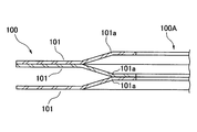
- FIG. 3 there is known a metal gasket 100 having a structure in which a plurality of metal plates 101 having elasticity having a half bead 101a formed along the outer periphery of the gas passage opening 101b is laminated (see Patent Document 1) ).
- the expansive graphite begins to disappear due to oxidation of the expanded graphite sheet 11 at 500 to 600 ° C. to carbon dioxide gas. Therefore, when used in a high temperature environment as described above, not only the expanded graphite is completely covered with the coated metal plate, but also the phlogopite or muscovite is processed to block the contact of the high temperature gas to the expanded graphite
- the mica sheet is polymerized to expanded graphite (see Patent Document 2), and the production cost is high.
- the present invention has been made in view of the foregoing, and the technical object thereof is to provide a heat resistant gasket capable of preventing stress relaxation by heat and maintaining excellent sealability even in a high temperature environment. It is in.
- the heat-resistant gasket according to the invention of claim 1 comprises a first coated plate made of metal on which an annular continuous embossed portion is formed, and the first coated plate Metal disposed opposite to each other in the thickness direction and in close contact with the convex surface of the embossed portion such that the end portions on the inner or outer circumferential side of the embossed portion are bonded closely to the first cover plate And a core made of expanded graphite held between the first cover plate and the second cover plate between the embossed portion and the end portion.
- the core made of expanded graphite has excellent compressive strength and elasticity even at high temperature, so that elastic recovery is obtained by receiving compression between the first cover plate and the second cover plate. It exerts a force and does not cause stress relaxation. And even in a high temperature environment, the core held between the first cover plate and the second cover plate is in contact with the high temperature gas or the high temperature air by the seal portion by the convex surface of the embossed portion and the seal portion by close polymerization between the end portions. Since it is shut off, the loss of expanded graphite due to oxidation is prevented. Therefore, the excellent sealability by the elasticity of the expanded graphite is maintained.
- a compression limiting plate is interposed between the first cover plate and the second cover plate and on the opposite side of the expanded graphite as viewed from the embossed portion. It is done.
- the compression limiting plate interposed between the first cover plate and the second cover plate prevents over-compression of the core made of expanded graphite.
- the heat-resistant gasket according to the invention of claim 3 is the construction according to claim 1 or 2, wherein a core made of metal is laminated on the expanded graphite of the core.
- a core made of metal laminated on expanded graphite of the core improves the handling property of the core at the time of manufacturing the gasket and reduces the amount of the expanded graphite used. It is.
- the core made of expanded graphite sandwiched between the first cover plate and the second cover plate has a high temperature due to the seal portion by the convex surface of the embossed portion and the seal portion by close polymerization between the end portions. Since the contact of gas and high temperature air is blocked, the loss due to oxidation can be prevented even in high temperature environment, and the compressive strength and elasticity can be maintained, and excellent heat-resistant sealability can be exhibited. Moreover, since expensive materials such as heat resistant steel plates are not used and the amount of expansive graphite used can be small, it can be provided at low cost.
- FIG. 2 is a cross-sectional view taken along the line II-II in FIG. It is a fragmentary sectional view showing an example of the heat resistant gasket concerning a prior art.
- the heat-resistant gasket in this embodiment has a square-rounded square planar shape as shown in FIG. 1, and a circular opening A on the gas flow path side is opened at the center and a pipe is formed at the corner A plurality of bolt insertion holes B are formed in order to insert bolts for joining the roads.
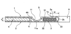
- the heat-resistant gasket has a first cover plate 1 on which an annular annular continuous embossed portion 11 concentric with the opening A is formed, and the first cover plate 1 is disposed opposite to the first cover plate 1 in the thickness direction.
- the second coated plate 2 is closely attached to the convex surface 11a of the second coated plate 2 and is bonded to the first coated plate 1 in close contact polymerization with each other at the end portions 1a and 2a of the inner peripheral side (opening A side) of the embossed portion 11 And a core 3 sandwiched between the first cover plate 1 and the second cover plate 2 between the embossed portion 11 and the end portions 1a and 2a; It has a compression limiting plate 4 interposed between two coated plates 2.
- the first cover plate 1 is made of a stainless steel plate, and the outer edge is a rounded square, and a circular hole (not shown) as a bolt insertion hole B is drilled in the corner.
- the embossed portion 11 is formed in a substantially semicircular arc shape so as to surround the part. In the appearance shown in FIG. 1, this embossed portion 11 is in the form of a circular groove.
- the second cover plate 2 is also made of a stainless steel plate, and the outer edge is a rounded square having the same shape and size as the first cover plate 1 and a circular hole (not shown) as a bolt insertion hole B at the corner.
- a portion of the embossed portion 11 facing the convex surface 11a having a substantially semicircular arc shape is brought into close contact with the convex surface 11a, and the end portion 2a on the inner peripheral side (opening A side) forms a substantially J-shaped cross section.
- the folded portion 2 b is in close contact polymerization state so as to cover the end portion 1 a on the inner peripheral side of the first cover plate 1.
- the second cover plate 2 is appropriately thinner than the first cover plate 1 to improve the concentrated surface pressure due to the tightening load in the mounted state and to seal the end portion 2 a of the second cover plate 2. We are trying to adjust the contact pressure.
- the core 3 is between the first cover plate 1 and the second cover plate 2 and is a close contact portion between the embossed portion 11 of the first cover plate 1 and the second cover plate 2 and the first cover plate 1 and the second cover plate 2.
- the annular space S enclosed by the end portions 1a and 2a intimately polymerized with each other is held between the first covering plate 1 and the second covering plate 2.
- the core 3 has a structure in which two annular expanded graphite sheets 31 and 32 and an annular core material 33 formed of steel plates between them are laminated.
- the compression limiting plate 4 is made of a stainless steel plate or an iron plate that is slightly thinner than the core 3, and the outer edge thereof forms a rounded square with the same shape and size as the first covering plate 1 and the second covering plate 2, A circular opening 4A larger in diameter than the embossed portion 11 is opened at the center, and a circular hole (not shown) as a bolt insertion hole B is bored at a corner.
- the height h of the embossed portion 11 of the first coated plate 1 is the thickness of the compression limiting plate 4 so that the convex surface 11 a of the embossed portion 11 is in close contact with the second coated plate 2 when the heat resistant gasket is tightened. It is set higher than t. Moreover, the folding
- the heat-resistant gasket configured as described above is, for example, interposed between joining flanges of a turbine outlet in a turbocharger and the like, and is sealed to seal high temperature gas flowing through the turbine outlet.
- the expanded graphite sheets 31 and 32 in the core 3 have excellent compressive strength and elasticity even at high temperatures of 800 ° C. or more, and do not cause stress relaxation. Then, the expanded graphite sheets 31 and 32 are oxidized by a high temperature gas or air containing oxygen in a high temperature environment of 500 ° C. or higher, and gradually disappear as carbon dioxide gas.
- the embossed portion 11 The seal portion by close contact of the convex surface 11a of the second cover plate 2 and the seal portion by close polymerization of the end portions 1a and 2a of the first cover plate 1 and the second cover plate 2 Since the inflow of the high temperature gas and the high temperature air into the annular space S in which the core 3 is accommodated is reliably shut off, the oxidation loss of the expanded graphite sheets 31 and 32 is effectively prevented. For this reason, even if stress relaxation is caused by the first covering plate 1 and the second covering plate 2 being exposed to high temperatures, excellent sealing performance can be exhibited with respect to high temperature exhaust gas flowing through the turbine outlet.
- the core 33 is interposed between the expanded graphite sheets 31 and 32. Therefore, the amount of use of the expanded graphite sheets 31 and 32 can be reduced.
- the core 3 is not encased by welding or the like of the first cover plate 1 and the second cover plate 2, but the end portion 1a on the inner peripheral side of the first cover plate 1; Since the core 3 and the compression limiting plate 4 are held as shown in FIG. 2 by the end portions 2a of the folded back portions 2b formed on the inner peripheral portion of the cover plate 2 being polymerized with each other, the manufacturing cost is reduced. In addition, the handleability of the core 3 at the time of manufacturing the gasket can be improved.
- the embossed portion may be formed on the second cover plate 2 and the convex surface thereof may be in close contact with the first cover plate 1. Further, the materials of the first cover plate 1, the second cover plate 2, the compression limiting plate 4 and the like are appropriately selected according to the use conditions and the like.
- the 1st covering board 1 is a 2nd covering board It may be relatively thinner than 2 or the first covering plate 1 and the second covering plate 2 may have the same thickness.
Landscapes
- Engineering & Computer Science (AREA)
- General Engineering & Computer Science (AREA)
- Mechanical Engineering (AREA)
- Gasket Seals (AREA)
Abstract
Description
1a,2a 端部
11 エンボス部
11a 凸面
2 第二被覆板
2b 折り返し部
3 コア
4 圧縮制限プレート
A 開口部
31,32 膨張黒鉛シート
33 芯材
Claims (3)
- 環状に連続したエンボス部が形成された金属製の第一被覆板と、この第一被覆板に厚さ方向に対向配置されると共に前記エンボス部の凸面に密接され前記エンボス部の内周側又は外周側の端部同士が前記第一被覆板と互いに密接重合された状態に結合された金属製の第二被覆板と、前記エンボス部と前記端部の間で前記第一被覆板と第二被覆板の間に挟持された膨張黒鉛からなるコアを備えることを特徴とする耐熱ガスケット。
- 第一被覆板と第二被覆板の間であってかつエンボス部から見て膨張黒鉛と反対側に、圧縮制限プレートが介在されたことを特徴とする請求項1に記載の耐熱ガスケット。
- コアの膨張黒鉛に金属製の芯材が積層されたことを特徴とする請求項1又は2に記載の耐熱ガスケット。
Priority Applications (2)
| Application Number | Priority Date | Filing Date | Title |
|---|---|---|---|
| US14/771,649 US10094473B2 (en) | 2013-03-01 | 2014-02-18 | Heat-resistant gasket |
| CN201480011380.7A CN105026808B (zh) | 2013-03-01 | 2014-02-18 | 耐热衬垫 |
Applications Claiming Priority (2)
| Application Number | Priority Date | Filing Date | Title |
|---|---|---|---|
| JP2013-040495 | 2013-03-01 | ||
| JP2013040495A JP6442133B2 (ja) | 2013-03-01 | 2013-03-01 | 耐熱ガスケット |
Publications (1)
| Publication Number | Publication Date |
|---|---|
| WO2014132832A1 true WO2014132832A1 (ja) | 2014-09-04 |
Family
ID=51428104
Family Applications (1)
| Application Number | Title | Priority Date | Filing Date |
|---|---|---|---|
| PCT/JP2014/053685 Ceased WO2014132832A1 (ja) | 2013-03-01 | 2014-02-18 | 耐熱ガスケット |
Country Status (4)
| Country | Link |
|---|---|
| US (1) | US10094473B2 (ja) |
| JP (1) | JP6442133B2 (ja) |
| CN (1) | CN105026808B (ja) |
| WO (1) | WO2014132832A1 (ja) |
Families Citing this family (2)
| Publication number | Priority date | Publication date | Assignee | Title |
|---|---|---|---|---|
| DE102017122233A1 (de) * | 2017-08-25 | 2019-02-28 | Elringklinger Ag | Metallische Dichtungsanordnung und und Verfahren zur Herstellung |
| US11287040B2 (en) * | 2018-08-09 | 2022-03-29 | Dana Automotive Systems Group, Llc | Extrusion resistant gasket |
Citations (3)
| Publication number | Priority date | Publication date | Assignee | Title |
|---|---|---|---|---|
| JPH0791549A (ja) * | 1993-09-20 | 1995-04-04 | Taiho Kogyo Co Ltd | 積層金属ガスケット |
| JPH11315930A (ja) * | 1998-05-07 | 1999-11-16 | Honda Motor Co Ltd | 高耐熱性ガスケット構造 |
| JP2004525319A (ja) * | 2001-05-09 | 2004-08-19 | メロール ソシエテ アノニム | 繊維インサートを有する金属継手 |
Family Cites Families (17)
| Publication number | Priority date | Publication date | Assignee | Title |
|---|---|---|---|---|
| US4518168A (en) * | 1984-03-02 | 1985-05-21 | Dana Corporation | Multi-thickness fire ring assembly |
| US4756561A (en) * | 1985-02-14 | 1988-07-12 | Mazda Motor Corporation | Sealing gasket |
| DE3528614A1 (de) * | 1985-08-09 | 1987-02-19 | Goetze Ag | Flachdichtung, insbesondere zylinderkopfdichtung fuer verbrennungskraftmaschinen |
| US4834399A (en) * | 1986-11-10 | 1989-05-30 | Ishikawa Gasket Co., Ltd. | Steel laminate gasket |
| JPH0313555Y2 (ja) * | 1987-04-21 | 1991-03-27 | ||
| US4867462A (en) * | 1988-05-16 | 1989-09-19 | Ishikawa Gasket Co., Ltd. | Steel laminate gasket with separate beads |
| US5560623A (en) * | 1990-04-04 | 1996-10-01 | Kabushiki Kaisha Ket And Ket | Metal gasket |
| JP2539057Y2 (ja) * | 1991-02-19 | 1997-06-18 | 石川ガスケット株式会社 | シリンダヘッドガスケット |
| JP2666097B2 (ja) | 1991-08-02 | 1997-10-22 | 宇部興産株式会社 | スラグ粉砕設備 |
| US5338046A (en) * | 1992-12-18 | 1994-08-16 | Dana Corporation | Composite powdered metal retaining ring |
| US5505466A (en) * | 1992-12-18 | 1996-04-09 | Dana Corporation | Cylinder head gasket with retaining ring and spring seal |
| US5630593A (en) * | 1994-09-12 | 1997-05-20 | Eg&G Pressure Science, Inc. | Pressure-energized sealing rings |
| EP0775856A1 (en) * | 1995-11-23 | 1997-05-28 | TAKO PAYEN S.p.a. | Exhaust tube gasket for combustion gases |
| JP3949666B2 (ja) * | 2004-03-09 | 2007-07-25 | 石川ガスケット株式会社 | シリンダヘッドガスケット |
| JP4325521B2 (ja) * | 2004-09-28 | 2009-09-02 | 住友金属工業株式会社 | ガスケット用ステンレス鋼板とその製造方法 |
| JP2009243540A (ja) | 2008-03-29 | 2009-10-22 | Daihatsu Motor Co Ltd | メタルガスケット |
| CN202140196U (zh) * | 2011-07-08 | 2012-02-08 | 田业中 | 一种大功率内燃机汽缸垫和密封结构 |
-
2013
- 2013-03-01 JP JP2013040495A patent/JP6442133B2/ja not_active Expired - Fee Related
-
2014
- 2014-02-18 US US14/771,649 patent/US10094473B2/en active Active
- 2014-02-18 CN CN201480011380.7A patent/CN105026808B/zh not_active Expired - Fee Related
- 2014-02-18 WO PCT/JP2014/053685 patent/WO2014132832A1/ja not_active Ceased
Patent Citations (3)
| Publication number | Priority date | Publication date | Assignee | Title |
|---|---|---|---|---|
| JPH0791549A (ja) * | 1993-09-20 | 1995-04-04 | Taiho Kogyo Co Ltd | 積層金属ガスケット |
| JPH11315930A (ja) * | 1998-05-07 | 1999-11-16 | Honda Motor Co Ltd | 高耐熱性ガスケット構造 |
| JP2004525319A (ja) * | 2001-05-09 | 2004-08-19 | メロール ソシエテ アノニム | 繊維インサートを有する金属継手 |
Also Published As
| Publication number | Publication date |
|---|---|
| US20160025224A1 (en) | 2016-01-28 |
| JP6442133B2 (ja) | 2018-12-19 |
| CN105026808A (zh) | 2015-11-04 |
| JP2014169717A (ja) | 2014-09-18 |
| CN105026808B (zh) | 2018-10-16 |
| US10094473B2 (en) | 2018-10-09 |
Similar Documents
| Publication | Publication Date | Title |
|---|---|---|
| JP4536765B2 (ja) | 金属ガスケット | |
| JP5736585B2 (ja) | 金属シリンダヘッドガスケット | |
| JP6246797B2 (ja) | 金属ガスケット | |
| JPH05602Y2 (ja) | ||
| JP2011511916A5 (ja) | ||
| US20110204580A1 (en) | Multilayer gasket with labyrinth stopper | |
| JP2016142387A (ja) | メタルガスケット | |
| JP4309409B2 (ja) | メタルガスケット | |
| WO2014132832A1 (ja) | 耐熱ガスケット | |
| WO2001096042A3 (en) | Metal gasket with cold formed stopper | |
| JP4127726B2 (ja) | シリンダヘッドガスケット | |
| JP4252094B2 (ja) | シリンダヘッドガスケット | |
| JP4056503B2 (ja) | 金属ガスケット | |
| JP5714964B2 (ja) | 渦巻形ガスケット | |
| JP2009097529A (ja) | 金属積層形ガスケット | |
| JP2015187454A (ja) | ガスケット | |
| JP4541399B2 (ja) | 金属製ガスケット | |
| CN213574343U (zh) | 四层结构的增压器垫片 | |
| JP2787041B2 (ja) | 金属積層形ガスケット | |
| JP5714966B2 (ja) | 渦巻形ガスケット | |
| JP2009243540A (ja) | メタルガスケット | |
| CN206093294U (zh) | 密封垫 | |
| KR102102401B1 (ko) | 터보차저용 배기 가스켓 | |
| JP6677301B2 (ja) | ガスケット | |
| KR20170136347A (ko) | 워밍업 촉매 컨버터 및 터보차저용 가스켓 |
Legal Events
| Date | Code | Title | Description |
|---|---|---|---|
| WWE | Wipo information: entry into national phase |
Ref document number: 201480011380.7 Country of ref document: CN |
|
| 121 | Ep: the epo has been informed by wipo that ep was designated in this application |
Ref document number: 14756656 Country of ref document: EP Kind code of ref document: A1 |
|
| WWE | Wipo information: entry into national phase |
Ref document number: 14771649 Country of ref document: US |
|
| NENP | Non-entry into the national phase |
Ref country code: DE |
|
| 122 | Ep: pct application non-entry in european phase |
Ref document number: 14756656 Country of ref document: EP Kind code of ref document: A1 |