WO2014129458A1 - ガスタービンシステム、ガスタービンの燃焼器制御装置、及びガスタービンの燃焼器制御方法 - Google Patents
ガスタービンシステム、ガスタービンの燃焼器制御装置、及びガスタービンの燃焼器制御方法 Download PDFInfo
- Publication number
- WO2014129458A1 WO2014129458A1 PCT/JP2014/053754 JP2014053754W WO2014129458A1 WO 2014129458 A1 WO2014129458 A1 WO 2014129458A1 JP 2014053754 W JP2014053754 W JP 2014053754W WO 2014129458 A1 WO2014129458 A1 WO 2014129458A1
- Authority
- WO
- WIPO (PCT)
- Prior art keywords
- gas turbine
- main nozzle
- detection
- combustor
- supply amount
- Prior art date
- Legal status (The legal status is an assumption and is not a legal conclusion. Google has not performed a legal analysis and makes no representation as to the accuracy of the status listed.)
- Ceased
Links
Images


Classifications
-
- F—MECHANICAL ENGINEERING; LIGHTING; HEATING; WEAPONS; BLASTING
- F02—COMBUSTION ENGINES; HOT-GAS OR COMBUSTION-PRODUCT ENGINE PLANTS
- F02C—GAS-TURBINE PLANTS; AIR INTAKES FOR JET-PROPULSION PLANTS; CONTROLLING FUEL SUPPLY IN AIR-BREATHING JET-PROPULSION PLANTS
- F02C9/00—Controlling gas-turbine plants; Controlling fuel supply in air- breathing jet-propulsion plants
- F02C9/26—Control of fuel supply
- F02C9/28—Regulating systems responsive to plant or ambient parameters, e.g. temperature, pressure, rotor speed
-
- F—MECHANICAL ENGINEERING; LIGHTING; HEATING; WEAPONS; BLASTING
- F02—COMBUSTION ENGINES; HOT-GAS OR COMBUSTION-PRODUCT ENGINE PLANTS
- F02C—GAS-TURBINE PLANTS; AIR INTAKES FOR JET-PROPULSION PLANTS; CONTROLLING FUEL SUPPLY IN AIR-BREATHING JET-PROPULSION PLANTS
- F02C7/00—Features, components parts, details or accessories, not provided for in, or of interest apart form groups F02C1/00 - F02C6/00; Air intakes for jet-propulsion plants
- F02C7/22—Fuel supply systems
- F02C7/222—Fuel flow conduits, e.g. manifolds
-
- F—MECHANICAL ENGINEERING; LIGHTING; HEATING; WEAPONS; BLASTING
- F02—COMBUSTION ENGINES; HOT-GAS OR COMBUSTION-PRODUCT ENGINE PLANTS
- F02C—GAS-TURBINE PLANTS; AIR INTAKES FOR JET-PROPULSION PLANTS; CONTROLLING FUEL SUPPLY IN AIR-BREATHING JET-PROPULSION PLANTS
- F02C9/00—Controlling gas-turbine plants; Controlling fuel supply in air- breathing jet-propulsion plants
- F02C9/16—Control of working fluid flow
- F02C9/20—Control of working fluid flow by throttling; by adjusting vanes
-
- F—MECHANICAL ENGINEERING; LIGHTING; HEATING; WEAPONS; BLASTING
- F02—COMBUSTION ENGINES; HOT-GAS OR COMBUSTION-PRODUCT ENGINE PLANTS
- F02C—GAS-TURBINE PLANTS; AIR INTAKES FOR JET-PROPULSION PLANTS; CONTROLLING FUEL SUPPLY IN AIR-BREATHING JET-PROPULSION PLANTS
- F02C9/00—Controlling gas-turbine plants; Controlling fuel supply in air- breathing jet-propulsion plants
- F02C9/26—Control of fuel supply
- F02C9/32—Control of fuel supply characterised by throttling of fuel
- F02C9/34—Joint control of separate flows to main and auxiliary burners
-
- F—MECHANICAL ENGINEERING; LIGHTING; HEATING; WEAPONS; BLASTING
- F02—COMBUSTION ENGINES; HOT-GAS OR COMBUSTION-PRODUCT ENGINE PLANTS
- F02C—GAS-TURBINE PLANTS; AIR INTAKES FOR JET-PROPULSION PLANTS; CONTROLLING FUEL SUPPLY IN AIR-BREATHING JET-PROPULSION PLANTS
- F02C9/00—Controlling gas-turbine plants; Controlling fuel supply in air- breathing jet-propulsion plants
- F02C9/48—Control of fuel supply conjointly with another control of the plant
- F02C9/50—Control of fuel supply conjointly with another control of the plant with control of working fluid flow
- F02C9/54—Control of fuel supply conjointly with another control of the plant with control of working fluid flow by throttling the working fluid, by adjusting vanes
-
- F—MECHANICAL ENGINEERING; LIGHTING; HEATING; WEAPONS; BLASTING
- F23—COMBUSTION APPARATUS; COMBUSTION PROCESSES
- F23K—FEEDING FUEL TO COMBUSTION APPARATUS
- F23K5/00—Feeding or distributing other fuel to combustion apparatus
-
- F—MECHANICAL ENGINEERING; LIGHTING; HEATING; WEAPONS; BLASTING
- F23—COMBUSTION APPARATUS; COMBUSTION PROCESSES
- F23R—GENERATING COMBUSTION PRODUCTS OF HIGH PRESSURE OR HIGH VELOCITY, e.g. GAS-TURBINE COMBUSTION CHAMBERS
- F23R3/00—Continuous combustion chambers using liquid or gaseous fuel
- F23R3/28—Continuous combustion chambers using liquid or gaseous fuel characterised by the fuel supply
-
- F—MECHANICAL ENGINEERING; LIGHTING; HEATING; WEAPONS; BLASTING
- F05—INDEXING SCHEMES RELATING TO ENGINES OR PUMPS IN VARIOUS SUBCLASSES OF CLASSES F01-F04
- F05D—INDEXING SCHEME FOR ASPECTS RELATING TO NON-POSITIVE-DISPLACEMENT MACHINES OR ENGINES, GAS-TURBINES OR JET-PROPULSION PLANTS
- F05D2220/00—Application
- F05D2220/30—Application in turbines
- F05D2220/32—Application in turbines in gas turbines
-
- F—MECHANICAL ENGINEERING; LIGHTING; HEATING; WEAPONS; BLASTING
- F05—INDEXING SCHEMES RELATING TO ENGINES OR PUMPS IN VARIOUS SUBCLASSES OF CLASSES F01-F04
- F05D—INDEXING SCHEME FOR ASPECTS RELATING TO NON-POSITIVE-DISPLACEMENT MACHINES OR ENGINES, GAS-TURBINES OR JET-PROPULSION PLANTS
- F05D2240/00—Components
- F05D2240/40—Use of a multiplicity of similar components
-
- F—MECHANICAL ENGINEERING; LIGHTING; HEATING; WEAPONS; BLASTING
- F05—INDEXING SCHEMES RELATING TO ENGINES OR PUMPS IN VARIOUS SUBCLASSES OF CLASSES F01-F04
- F05D—INDEXING SCHEME FOR ASPECTS RELATING TO NON-POSITIVE-DISPLACEMENT MACHINES OR ENGINES, GAS-TURBINES OR JET-PROPULSION PLANTS
- F05D2260/00—Function
- F05D2260/80—Diagnostics
-
- F—MECHANICAL ENGINEERING; LIGHTING; HEATING; WEAPONS; BLASTING
- F05—INDEXING SCHEMES RELATING TO ENGINES OR PUMPS IN VARIOUS SUBCLASSES OF CLASSES F01-F04
- F05D—INDEXING SCHEME FOR ASPECTS RELATING TO NON-POSITIVE-DISPLACEMENT MACHINES OR ENGINES, GAS-TURBINES OR JET-PROPULSION PLANTS
- F05D2270/00—Control
- F05D2270/01—Purpose of the control system
- F05D2270/09—Purpose of the control system to cope with emergencies
- F05D2270/091—Purpose of the control system to cope with emergencies in particular sudden load loss
-
- F—MECHANICAL ENGINEERING; LIGHTING; HEATING; WEAPONS; BLASTING
- F05—INDEXING SCHEMES RELATING TO ENGINES OR PUMPS IN VARIOUS SUBCLASSES OF CLASSES F01-F04
- F05D—INDEXING SCHEME FOR ASPECTS RELATING TO NON-POSITIVE-DISPLACEMENT MACHINES OR ENGINES, GAS-TURBINES OR JET-PROPULSION PLANTS
- F05D2270/00—Control
- F05D2270/30—Control parameters, e.g. input parameters
- F05D2270/331—Mechanical loads
-
- Y—GENERAL TAGGING OF NEW TECHNOLOGICAL DEVELOPMENTS; GENERAL TAGGING OF CROSS-SECTIONAL TECHNOLOGIES SPANNING OVER SEVERAL SECTIONS OF THE IPC; TECHNICAL SUBJECTS COVERED BY FORMER USPC CROSS-REFERENCE ART COLLECTIONS [XRACs] AND DIGESTS
- Y02—TECHNOLOGIES OR APPLICATIONS FOR MITIGATION OR ADAPTATION AGAINST CLIMATE CHANGE
- Y02E—REDUCTION OF GREENHOUSE GAS [GHG] EMISSIONS, RELATED TO ENERGY GENERATION, TRANSMISSION OR DISTRIBUTION
- Y02E20/00—Combustion technologies with mitigation potential
- Y02E20/16—Combined cycle power plant [CCPP], or combined cycle gas turbine [CCGT]
Definitions
- the present invention relates to a gas turbine system, a gas turbine combustor control device, and a gas turbine combustor control method.
- This application claims priority based on Japanese Patent Application No. 2013-031186 for which it applied to Japan on February 20, 2013, and uses the content here.
- a gas turbine combustor is incorporated in a gas turbine plant or a combined cycle power plant, and combustion gas from the gas turbine combustor is introduced into the gas turbine to drive the gas turbine.
- Patent Document 1 Various techniques relating to such a background are known (for example, see Patent Document 1).
- the gas turbine system disclosed in Patent Document 1 outputs a first main nozzle control signal based on a predetermined function value according to a load.
- the second main nozzle function unit outputs a second main nozzle control signal based on a predetermined function value according to the operating state of the gas turbine.
- the tracking circuit causes the second main nozzle control signal to follow the first main nozzle control signal and outputs a third main nozzle control signal.
- the pilot nozzle function unit outputs a control signal based on a predetermined function value in order to open and close the pilot nozzle distribution valve in accordance with the third main nozzle control signal, and uses this signal as a pilot nozzle control signal.
- the control means uses the third main nozzle control signal as a main nozzle control signal.
- Patent Document 2 Various techniques relating to such a background are known (for example, see Patent Document 2).
- the gas turbine system described in Patent Document 2 acquires the pilot ratio of the fuel supplied to the combustor.
- the second information acquisition unit acquires the flow rate of air supplied to the combustor.
- the target fuel / air ratio acquisition unit has combustion maintenance limit information indicating the relationship between the pilot ratio determined by the stability of the combustion state in the combustor and the fuel / air ratio. Further, the target fuel / air ratio acquisition unit acquires the fuel / air ratio corresponding to the pilot ratio acquired by the first information acquisition unit from the combustion maintenance limit information, and outputs the fuel / air ratio as the target fuel / air ratio.
- the command creation unit determines the minimum fuel command using the target fuel-air ratio and the air flow rate acquired by the second information acquisition unit.
- Patent Document 1 tracks the main fuel to a set value and cannot control the timing of turning off during staging, and thus cannot reliably prevent misfire of the combustor.
- Patent Document 2 Although the technology described in Patent Document 2 can perform stable combustion at the time of load interruption, it is not intended for premixed pilots, and it cannot reliably prevent the combustor misfire because it does not consider the staging of the main nozzle. .
- the gas turbine system includes a gas turbine and a combustor control device.
- the gas turbine includes a combustor having a pilot nozzle that injects premixed fuel, and a first main nozzle and a second main nozzle that are provided around the pilot nozzle and inject premixed fuel.
- the combustor control device includes a load interruption detection unit that detects load interruption of a gas turbine, a pilot nozzle flow rate control unit that increases the amount of premixed fuel supplied to the pilot nozzle based on detection of load interruption, and a load interruption
- a load interruption detection unit that detects load interruption of a gas turbine
- pilot nozzle flow rate control unit that increases the amount of premixed fuel supplied to the pilot nozzle based on detection of load interruption
- a load interruption A first main nozzle flow rate controller that reduces the amount of premixed fuel supplied to the first main nozzle based on the detection of the first main nozzle, and a amount of premixed fuel supplied to the second main nozzle based on the detection of load interruption
- a second main nozzle flow rate control unit for further reducing the supply amount after a predetermined time has elapsed.
- the combustor control device may temporarily reduce the flow rate of the first main nozzle based on detection of load interruption.
- the combustor control device may reduce the amount of premixed fuel supplied to the second main nozzle by using parameters necessary for the flame as an index.
- the combustor control device decreases the supply amount of the premixed fuel to the second main nozzle to a predetermined amount based on detection of load interruption, and further decreases the supply amount after a predetermined time has elapsed. In this case, a delay time may be set.
- the combustor control device may include opening adjustment of the inlet guide vane provided in the gas turbine.
- a combustor control device for a gas turbine includes a load cutoff detection unit that detects a load cutoff of the gas turbine, and supply of premixed fuel for a pilot nozzle based on the detection of the load cutoff. Based on a pilot nozzle flow control unit that increases the amount, a first main nozzle flow control unit that decreases the amount of premixed fuel supplied to the first main nozzle based on detection of load interruption, and on detection of load interruption And a second main nozzle flow rate controller that further reduces the supply amount after a predetermined time has elapsed after reducing the supply amount of the premixed fuel to the second main nozzle to a predetermined amount.
- a method for controlling a combustor for a gas turbine includes a load cutoff detection stage for detecting a load cutoff of the gas turbine, and supply of premixed fuel for a pilot nozzle based on the detection of the load cutoff. Based on the pilot nozzle flow rate control stage to increase the amount, the first main nozzle flow rate control stage to decrease the supply amount of the premixed fuel to the first main nozzle based on the detection of the load cutoff, and on the basis of the detection of the load cutoff And a second main nozzle flow rate control step of further reducing the supply amount after elapse of a predetermined time after the supply amount of the premixed fuel to the second main nozzle is reduced to a predetermined amount.
- misfire of the combustor can be reliably prevented.
- FIG. 1 is a conceptual block configuration diagram of a gas turbine system according to a first embodiment.
- the gas turbine system 1 includes a gas turbine 10 and a combustor control device 11.
- the gas turbine 10 includes a combustor 12.
- the combustor 12 includes a pilot nozzle 13, a first main nozzle 14, and a second main nozzle 15.
- the combustor control device 11 includes a load cutoff detection unit 16, a pilot nozzle flow rate control unit 17, a first main nozzle flow rate control unit 18, and a second main nozzle flow rate control unit 19.
- the pilot nozzle 13 injects premixed fuel gas.
- the first main nozzle 14 injects premixed fuel gas around the pilot nozzle 13. Similar to the first main nozzle 14, the second main nozzle 15 injects premixed fuel gas around the pilot nozzle 13.
- the load cutoff detection unit 16 detects the load cutoff of the gas turbine 10.
- the pilot nozzle flow rate control unit 17 increases the supply amount of the premixed fuel gas from the pilot nozzle 13 based on detection of load interruption.
- the first main nozzle flow rate control unit 18 decreases the supply amount of the premixed fuel gas to the first main nozzle 14 based on the detection of load interruption.
- the second main nozzle flow rate control unit 19 reduces the supply amount of the premixed fuel gas to the second main nozzle 15 to a predetermined amount based on the detection of load interruption, and then reduces the supply amount after elapse of a predetermined time. Further decrease.
- the main nozzles are not limited to the first main nozzle 14 and the second main nozzle 15, but may be a plurality including the third main nozzle and the fourth main nozzle. In that case, among the plural groups of main nozzles, control is performed such that several systems are left for rotational speed control and the remaining several systems are decreased with a time difference.
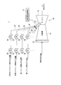
- FIG. 2 is a schematic diagram of the gas turbine system of the first embodiment.
- the gas turbine 10 includes a compressor 21 on the intake side of the turbine body 20.
- the gas turbine 10 includes an inlet guide vane 22 for adjusting the intake air amount on the intake air intake side.
- a premixed pilot fuel gas passage 23 a diffusion pilot fuel gas passage 24, a first main nozzle fuel gas passage 25, and a second main nozzle fuel gas passage 26 are connected in communication.
- the combustor 12 is connected to a plurality of top hat fuel gas passages such as a first top hat fuel gas passage 27 and a second top hat fuel gas passage 28.
- the premixed pilot fuel gas flow path 23 is connected to the premixed combustion pilot pressure regulating valve 29 and the premixed combustion pilot flow regulating valve 30 in communication from the upstream side to the downstream side of the fuel gas.
- the diffusion pilot fuel gas flow path 24 is connected to the diffusion combustion pilot pressure regulating valve 31 and the diffusion combustion pilot flow regulating valve 32 in communication from the upstream side to the downstream side of the fuel gas.
- the first main nozzle fuel gas flow path 25 is connected in communication with the first main nozzle pressure regulating valve 33 and the first main nozzle flow regulating valve 34 from the upstream side to the downstream side of the fuel gas.
- the second main nozzle fuel gas flow path 26 is connected in communication with the second main nozzle pressure regulating valve 35 and the second main nozzle flow regulating valve 36 from the upstream side to the downstream side of the fuel gas.
- FIG. 3 is a schematic cross-sectional view of the combustor in the gas turbine of the first embodiment.
- the combustor 12 is provided with a pilot nozzle 13 at the center, and three first main nozzles 14 are arranged in the circumferential direction on the outer peripheral side of the pilot nozzle 13.
- five second main nozzles 15 are arranged in the circumferential direction on the outer peripheral side of the pilot nozzle 13.
- positioning and the number of each nozzle can be set suitably.
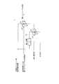
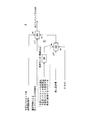
- FIG. 4 is a schematic circuit diagram of the combustor control device for the gas turbine of the first embodiment.
- the load cutoff signal during the premix pilot is input to the first switch SW1.
- the load cutoff signal at the time of the premix pilot is input to the second switch SW1 with the remaining time set by the delay circuit D.
- the fuel flow rate command calculation signal of the second main nozzle 15 by the normal control is input to the off input of the first switch SW1.
- the remaining set amount signal is input to the off input of the second switch SW2.
- the zero signal is input to the on input of the second switch SW2.
- the second switch SW2 is input to the on input of the first switch SW1.
- the combustor control device 11 determines the fuel flow rate command to the second main nozzle 15 by the normal control by the first switch SW1. On the other hand, when the load is interrupted, a delay time is set in the delay circuit D, and then the fuel flow rate command to the second main nozzle 15 is determined through the second switch SW2 and the first switch SW1.
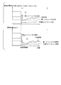
- FIG. 5 is a timing chart for explaining the gas turbine combustor control method according to the first embodiment.
- the combustor control device 11 detects the load cutoff command.
- the pilot nozzle flow rate control unit 17 increases the supply amount of the premixed fuel gas from the pilot nozzle 13 by detecting the load cutoff command. Therefore, at the time point t2 after the time point t1, the first main nozzle flow rate control unit 18 decreases the supply amount of the premixed fuel gas to the first main nozzle 14.
- the second main nozzle flow rate control unit 19 further reduces the supply amount after time t2 when the supply amount of the premixed fuel gas to the second main nozzle 15 is reduced to a predetermined amount. Accordingly, the second main nozzle 15 continues to supply a predetermined amount of fuel gas in a predetermined period. During this time, the flame is held by raising the supply of the premixed pilot fuel gas.
- the premixed pilot fuel gas is increased and the second main nozzle 15 is not immediately shut off, and a predetermined amount of fuel gas is supplied for a predetermined period. to continue. During this time, the supply of premixed pilot fuel gas is started. Therefore, according to the gas turbine system 1, it is possible to urge the fire transfer from the main system to surely prevent the flame loss of the combustor 12.
- the supply of a predetermined amount of fuel gas is continued by the second main nozzle 15 for a predetermined period, and the supply of the premixed pilot fuel gas is started during this period. . Therefore, according to the combustor control device 11 of the gas turbine, misfire of the combustor 12 can be prevented by flame holding.
- the supply of the predetermined amount of fuel gas is continued by the second main nozzle 15 for a predetermined period, and the supply of the premixed pilot fuel gas is started during this period. Therefore, according to the combustor control method of the gas turbine, misfire of the combustor 12 can be prevented by flame holding.
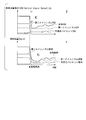
- FIG. 6 is a timing chart for explaining the combustor control method for the gas turbine of the second embodiment.
- the gas turbine system 2 of the second embodiment includes a combustor control device 41.
- the combustor control method of the gas turbine according to the present embodiment increases the premixed pilot fuel gas at the time of load interruption at time t1, and does not immediately shut off the second main nozzle 15, but a predetermined amount of fuel gas in a predetermined period. Continue to supply. Then, the fuel gas supply amount of the first main nozzle 14 is temporarily reduced until time t2 after time t1.
- the premixed pilot fuel gas is increased, and a predetermined amount of fuel gas is supplied for a predetermined period without immediately shutting off the second main nozzle 15. to continue.
- the supply of the premixed pilot fuel gas is started, and the fuel gas supply amount of the first main nozzle 14 is temporarily reduced. Therefore, according to the gas turbine system 2, the combustor control apparatus 11 which can suppress the significant increase in the rotation speed of the gas turbine 10 can be provided.
- the supply of the predetermined amount of fuel gas is continued by the second main nozzle 15 for a predetermined period, and the supply of the premixed pilot fuel gas is started during this period.
- the fuel gas supply amount of the first main nozzle 14 is temporarily reduced. Therefore, according to the combustor control device 41 of the gas turbine, it is possible to suppress a significant increase in the rotational speed of the gas turbine 10.
- the supply of the predetermined amount of fuel gas is continued by the second main nozzle 15 for a predetermined period, and during this period, the supply of the premixed pilot fuel gas is started.
- the fuel gas supply amount of the first main nozzle 14 is temporarily reduced. Therefore, according to the combustor control method for a gas turbine of the present embodiment, a significant increase in the rotational speed of the gas turbine 10 can be suppressed.
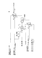
- FIG. 7 is a schematic circuit diagram of a combustor control device for a gas turbine according to a third embodiment.
- the combustor control device 51 included in the gas turbine system 3 includes a high value monitor HM that sets a threshold value.
- the combustor control device 51 performs automatic cutting using parameters such as the premixed pilot flame temperature, the premixed pilot fuel flow rate, and the premixed pilot fuel / air ratio, which are important for flame holding, as indexes. Since the flame temperature is difficult to measure directly, an estimated value is calculated using a table from various state quantities such as the passenger compartment temperature, fuel temperature, and fuel-air ratio.
- the gas turbine system 3 of the third embodiment it is possible to provide the combustor control device 51 that can reliably prevent misfire and can suppress fuel increase at an appropriate timing, thereby suppressing an increase in the rotational speed of the gas turbine 10. .
- misfire can be reliably prevented and fuel can be cut off at an appropriate timing, so that an increase in the rotational speed of the gas turbine 10 can be suppressed.
- misfire can be reliably prevented, and fuel can be cut at an appropriate timing, so that an increase in the rotational speed of the gas turbine 10 can be suppressed.
- FIG. 8 is a schematic circuit diagram of a combustor control device for a gas turbine according to a fourth embodiment.
- the combustor control device 61 included in the gas turbine system 4 includes a rate limiter RL that sets a rate.
- the rate limiter RL sets the rate by the output of the switch SW3 for setting the remaining set amount and the output of the switch SW2.
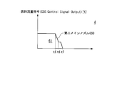
- FIG. 9 is a timing chart for explaining the gas turbine combustor control method of the fourth embodiment. As shown in FIG. 9, in the gas turbine combustor control method, the remaining set amount is set to decrease stepwise at time t6 and time t7 after time t5.
- the gas turbine system 4 of the fourth embodiment it is possible to provide the combustor control device 61 that can prevent fuel waste by setting the fuel gas supply amount of the second main nozzle 15 in detail.
- waste of fuel can be prevented by setting the fuel gas supply amount of the second main nozzle 15 in detail.
- waste of fuel can be prevented by setting the fuel gas supply amount of the second main nozzle 15 in detail.
- FIG. 10 is a timing chart for explaining the gas turbine combustor control method according to the fifth embodiment.
- the gas turbine system 5 of the fifth embodiment includes a combustor control device 71.
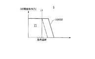
- the gas turbine combustor control method according to the present embodiment adjusts the air flow rate by adjusting the opening degree of the inlet guide vanes 22 together with the combustion side control.
- the adjustment of the opening degree of the inlet guide vanes 22 can set parameters for dead time and rate.
- the dead time is set or the rate is slowed down. By doing so, the air flow rate can be increased.
- the combustor control device 71 that can suppress the maximum rotational speed of the gas turbine 10 can be provided.
- the air flow rate can be increased and the power of the compressor 21 can be increased, so that the maximum rotational speed of the gas turbine 10 can be suppressed.
- the air flow rate can be increased and the power of the compressor 21 can be increased, so that the maximum rotational speed of the gas turbine 10 can be suppressed.
- gas turbine system the gas turbine combustor control device, and the gas turbine combustor control method are not limited to the above-described embodiments, and appropriate modifications and improvements can be made.
- the second embodiment, the third embodiment, the fourth embodiment, and the fifth embodiment may be combined.
- misfire of the combustor can be reliably prevented.
Landscapes
- Engineering & Computer Science (AREA)
- Chemical & Material Sciences (AREA)
- Combustion & Propulsion (AREA)
- Mechanical Engineering (AREA)
- General Engineering & Computer Science (AREA)
- Physics & Mathematics (AREA)
- Fluid Mechanics (AREA)
- Control Of Turbines (AREA)
Abstract
Description
本願は、2013年2月20日に、日本に出願された特願2013-031186号に基づき優先権を主張し、その内容をここに援用する。
パイロットノズル関数器は、第3のメインノズル制御信号に応じてパイロットノズル分配弁を開閉動作させるために所定の関数値に基づく制御信号を出力しこの信号をパイロットノズル制御信号とする。制御手段は、第3のメインノズル制御信号をメインノズル制御信号とする。このように、このガスタービンシステムによっては、安定した2段燃焼を行うことができ、負荷遮断時にパイロットノズル分配弁を所定開度としてパイロットノズルの失火を防止できる。
図1は、第1実施形態のガスタービンシステムの概念ブロック構成図である。図1に示すように、ガスタービンシステム1は、ガスタービン10、燃焼器制御装置11を備える。ガスタービン10は、燃焼器12を備える。燃焼器12は、パイロットノズル13、第一メインノズル14、第二メインノズル15を備える。燃焼器制御装置11は、負荷遮断検出部16、パイロットノズル流量制御部17、第一メインノズル流量制御部18、第二メインノズル流量制御部19を備える。
第一メインノズル燃料ガス流路25は、燃料ガスの上流側から下流側に向けて、第一メインノズル圧調弁33、第一メインノズル流調弁34をそれぞれ連通接続している。第二メインノズル燃料ガス流路26は、燃料ガスの上流側から下流側に向けて、第二メインノズル圧調弁35、第二メインノズル流調弁36をそれぞれ連通接続している。
次に、第2実施形態について図6を参照しながら説明するが、第1実施形態と同一の部位には同一の符号を付してその説明は省略し、異なる点についてのみ説明する。図6は、第2実施形態のガスタービンの燃焼器制御方法を説明するタイミングチャートである。図6に示すように、第2実施形態のガスタービンシステム2は燃焼器制御装置41を備える。本実施形態のガスタービンの燃焼器制御方法は、時点t1における負荷遮断時に、予混合パイロット燃料ガスを増加させるとともに第二メインノズル15を即時に遮断せずに所定の期間において所定量の燃料ガスの供給を続ける。そして、時点t1の以後の時点t2までの間において、第一メインノズル14の燃料ガス供給量を一時的に絞る。
次に、第3実施形態について図7を参照しながら説明するが、第1実施形態と同一の部位には同一の符号を付してその説明は省略し、異なる点についてのみ説明する。図7は、第3実施形態のガスタービンの燃焼器制御装置の模式的回路図である。図7に示すように、ガスタービンシステム3に有する燃焼器制御装置51は、閾値を設定する高値モニタHMを備える。燃焼器制御装置51は、保炎に重要な、予混合パイロット火炎温度、予混パイロット燃料流量、予混パイロット燃空比等のパラメータを指標として自動切りを実施する。なお、火炎温度は直接測りにくいので、車室温度、燃料温度、燃空比等の各種状態量からのテーブルで推定値を算出する。
次に、第4実施形態について図8を参照しながら説明するが、第1実施形態と同一の部位には同一の符号を付してその説明は省略し、異なる点についてのみ説明する。図8は、第4実施形態のガスタービンの燃焼器制御装置の模式的回路図である。図8に示すように、ガスタービンシステム4に有する燃焼器制御装置61は、レートを設定するレートリミッタRLを備える。レートリミッタRLは、残し設定量を設定するためのスイッチSW3の出力と、スイッチSW2の出力とによりレートを設定する。
次に、第5実施形態について図10を参照しながら説明するが、第1実施形態と同一の部位には同一の符号を付してその説明は省略し、異なる点についてのみ説明する。図10は、第5実施形態のガスタービンの燃焼器制御方法を説明するタイミングチャートである。図10に示すように、第5実施形態のガスタービンシステム5は燃焼器制御装置71を備える。本実施形態のガスタービンの燃焼器制御方法は、燃焼側の制御とともに入口案内翼22の開度を調整して空気流量を調整する。ここで、入口案内翼22の開度の調整は、無駄時間、レートをパラメータ設定できる。例えば、図10に仮想線で示したように、入口案内翼を機械的な最大速度で閉めた場合と比べて、時点t1において負荷遮断があった後に、無駄時間を設定したり、レートを遅くしたりすることにより、空気流量を増加できる。
2 ガスタービンシステム
3 ガスタービンシステム
4 ガスタービンシステム
5 ガスタービンシステム
10 ガスタービン
11 燃焼器制御装置
13 パイロットノズル
14 第一メインノズル
15 第二メインノズル
16 負荷遮断検出部
17 パイロットノズル流量制御部
18 第一メインノズル流量制御部
19 第二メインノズル流量制御部
41 燃焼器制御装置
51 燃焼器制御装置
61 燃焼器制御装置
71 燃焼器制御装置
Claims (7)
- 予混合燃料を噴射するパイロットノズルと、
前記パイロットノズルの周囲に設けられて予混合燃料を噴射する第一メインノズル及び第二メインノズルと
を有する燃焼器を備えたガスタービンと、
前記ガスタービンの負荷遮断を検出する負荷遮断検出部と、
前記負荷遮断の検出に基づいて、前記パイロットノズルの予混合燃料の供給量を増加させるパイロットノズル流量制御部と、
前記負荷遮断の検出に基づいて、前記第一メインノズルへの予混合燃料の供給量を減少させる第一メインノズル流量制御部と、
前記負荷遮断の検出に基づいて、前記第二メインノズルへの予混合燃料の供給量を所定量まで減少させた後、予め定めた時間の経過後に前記供給量をさらに減少させる第二メインノズル流量制御部と
を有する燃焼器制御装置と
を備えるガスタービンシステム。 - 前記燃焼器制御装置は、前記負荷遮断の検出に基づいて、前記第一メインノズルの流量を一時的に減少させる
請求項1に記載のガスタービンシステム。 - 前記燃焼器制御装置は、火炎に必要なパラメータを指標として前記第二メインノズルへの予混合燃料の供給量を減少させる
請求項1に記載のガスタービンシステム。 - 前記燃焼器制御装置は、前記負荷遮断の検出に基づいて、前記第二メインノズルへの予混合燃料の供給量を所定量まで減少させた後、予め定めた時間の経過後に該供給量をさらに減少させる際に、遅延時間を設定する
請求項1に記載のガスタービンシステム。 - 前記燃焼器制御装置は、前記ガスタービンに有する入口案内翼の開度調整を含める
請求項1から4のいずれか一項に記載のガスタービンシステム。 - ガスタービンの負荷遮断を検出する負荷遮断検出部と、
前記負荷遮断の検出に基づいて、パイロットノズルの予混合燃料の供給量を増加させるパイロットノズル流量制御部と、
前記負荷遮断の検出に基づいて、第一メインノズルへの予混合燃料の供給量を減少させる第一メインノズル流量制御部と、
前記負荷遮断の検出に基づいて、第二メインノズルへの予混合燃料の供給量を所定量まで減少させた後、予め定めた時間の経過後に該供給量をさらに減少させる第二メインノズル流量制御部と
を備えるガスタービンの燃焼器制御装置。 - ガスタービンの負荷遮断を検出する負荷遮断検出段階と、
前記負荷遮断の検出に基づいて、パイロットノズルの予混合燃料の供給量を増加させるパイロットノズル流量制御段階と、
前記負荷遮断の検出に基づいて、第一メインノズルへの予混合燃料の供給量を減少させる第一メインノズル流量制御段階と、
前記負荷遮断の検出に基づいて、第二メインノズルへの予混合燃料の供給量を所定量まで減少させた後、予め定めた時間の経過後に該供給量をさらに減少させる第二メインノズル流量制御段階と
を備えるガスタービンの燃焼器制御方法。
Priority Applications (4)
| Application Number | Priority Date | Filing Date | Title |
|---|---|---|---|
| CN201480005078.0A CN104919159B (zh) | 2013-02-20 | 2014-02-18 | 燃气轮机系统、燃气轮机的燃烧器控制装置以及燃气轮机的燃烧器控制方法 |
| DE112014000907.5T DE112014000907B4 (de) | 2013-02-20 | 2014-02-18 | Gasturbinensystem, Gasturbinenbrennkammer-Steuervorrichtung und Gasturbinenbrennkammer-Steuerverfahren |
| US14/760,519 US20150354467A1 (en) | 2013-02-20 | 2014-02-18 | Gas turbine system, gas turbine combustor control device, and gas turbine combustor control method |
| KR1020157018842A KR101707361B1 (ko) | 2013-02-20 | 2014-02-18 | 연소기 제어 장치, 가스 터빈 시스템 및 가스 터빈의 연소기 제어 방법 |
Applications Claiming Priority (2)
| Application Number | Priority Date | Filing Date | Title |
|---|---|---|---|
| JP2013-031186 | 2013-02-20 | ||
| JP2013031186A JP5972810B2 (ja) | 2013-02-20 | 2013-02-20 | ガスタービンシステム、ガスタービンの燃焼器制御装置、及びガスタービンの燃焼器制御方法 |
Publications (1)
| Publication Number | Publication Date |
|---|---|
| WO2014129458A1 true WO2014129458A1 (ja) | 2014-08-28 |
Family
ID=51391248
Family Applications (1)
| Application Number | Title | Priority Date | Filing Date |
|---|---|---|---|
| PCT/JP2014/053754 Ceased WO2014129458A1 (ja) | 2013-02-20 | 2014-02-18 | ガスタービンシステム、ガスタービンの燃焼器制御装置、及びガスタービンの燃焼器制御方法 |
Country Status (6)
| Country | Link |
|---|---|
| US (1) | US20150354467A1 (ja) |
| JP (1) | JP5972810B2 (ja) |
| KR (1) | KR101707361B1 (ja) |
| CN (1) | CN104919159B (ja) |
| DE (1) | DE112014000907B4 (ja) |
| WO (1) | WO2014129458A1 (ja) |
Cited By (1)
| Publication number | Priority date | Publication date | Assignee | Title |
|---|---|---|---|---|
| US11421886B2 (en) | 2015-07-31 | 2022-08-23 | Mitsubishi Heavy Industries, Ltd. | Fuel flow rate setting method, device for implementing said method, and gas turbine plant provided with said device |
Families Citing this family (5)
| Publication number | Priority date | Publication date | Assignee | Title |
|---|---|---|---|---|
| JP6807638B2 (ja) * | 2015-12-07 | 2021-01-06 | 三菱パワー株式会社 | 燃焼制御システム、ガスタービン、燃焼制御方法及びプログラム |
| JP6935327B2 (ja) * | 2017-12-28 | 2021-09-15 | 三菱パワー株式会社 | 制御装置、ガスタービン、制御方法及びプログラム |
| EP3524799A1 (de) * | 2018-02-13 | 2019-08-14 | Siemens Aktiengesellschaft | Verfahren zum betreiben einer brenneranordnung einer gasturbine |
| JP7252861B2 (ja) * | 2019-08-22 | 2023-04-05 | 三菱重工業株式会社 | ガスタービンの燃焼制御装置、燃焼制御方法及びプログラム |
| JP2025129943A (ja) * | 2024-02-26 | 2025-09-05 | 川崎重工業株式会社 | ガスタービンエンジンの制御装置および制御方法 |
Citations (3)
| Publication number | Priority date | Publication date | Assignee | Title |
|---|---|---|---|---|
| JPH05149544A (ja) * | 1991-11-27 | 1993-06-15 | Toshiba Corp | ガスタービンの制御装置 |
| JPH08178290A (ja) * | 1994-12-20 | 1996-07-12 | Toshiba Corp | ガスタービン燃料供給装置 |
| JP2011085105A (ja) * | 2009-10-19 | 2011-04-28 | Mitsubishi Heavy Ind Ltd | ガスタービン制御装置及び発電システム |
Family Cites Families (13)
| Publication number | Priority date | Publication date | Assignee | Title |
|---|---|---|---|---|
| US4280059A (en) * | 1979-12-26 | 1981-07-21 | United Technologies Corporation | Detecting power loss in free turbines |
| JP3039947B2 (ja) * | 1990-03-19 | 2000-05-08 | 株式会社日立製作所 | ガスタービンの燃料制御装置 |
| JPH06317284A (ja) * | 1993-05-06 | 1994-11-15 | Sanyo Electric Co Ltd | ポンプ |
| DE4429539C2 (de) * | 1994-08-19 | 2002-10-24 | Alstom | Verfahren zur Drehzahlregelung einer Gasturbine bei Lastabwurf |
| US5896736A (en) * | 1997-03-06 | 1999-04-27 | General Electric Company | Load rejection rapid acting fuel-air controller for gas turbine |
| JP3771677B2 (ja) * | 1997-07-07 | 2006-04-26 | 三菱重工業株式会社 | パイロット比自動調整装置 |
| US20050274115A1 (en) * | 2004-06-15 | 2005-12-15 | Pearce Kevin P | Method and Apparatus for Prevention of Compressor Stall and Combustion Flameout in a Turbine Engine |
| JP4642630B2 (ja) * | 2005-10-20 | 2011-03-02 | カワサキプラントシステムズ株式会社 | ガスタービンの制御システムおよび制御方法 |
| US7457688B2 (en) * | 2006-09-19 | 2008-11-25 | General Electric Company | Method and system for detection and transfer to electrical island operation |
| EP1944547A1 (en) * | 2007-01-15 | 2008-07-16 | Siemens Aktiengesellschaft | Method of controlling a fuel split |
| JP5185757B2 (ja) * | 2008-10-01 | 2013-04-17 | 三菱重工業株式会社 | ガスタービンの燃料制御方法および燃料制御装置ならびにガスタービン |
| US8997499B2 (en) * | 2009-03-04 | 2015-04-07 | Alstom Technology Ltd | Load rejection and recovery using a secondary fuel nozzle |
| JP2012197701A (ja) * | 2011-03-18 | 2012-10-18 | Mitsubishi Heavy Ind Ltd | ガスタービン設備、その燃料ガス制御装置及びその燃料ガス制御方法 |
-
2013
- 2013-02-20 JP JP2013031186A patent/JP5972810B2/ja active Active
-
2014
- 2014-02-18 CN CN201480005078.0A patent/CN104919159B/zh active Active
- 2014-02-18 KR KR1020157018842A patent/KR101707361B1/ko active Active
- 2014-02-18 DE DE112014000907.5T patent/DE112014000907B4/de active Active
- 2014-02-18 US US14/760,519 patent/US20150354467A1/en not_active Abandoned
- 2014-02-18 WO PCT/JP2014/053754 patent/WO2014129458A1/ja not_active Ceased
Patent Citations (3)
| Publication number | Priority date | Publication date | Assignee | Title |
|---|---|---|---|---|
| JPH05149544A (ja) * | 1991-11-27 | 1993-06-15 | Toshiba Corp | ガスタービンの制御装置 |
| JPH08178290A (ja) * | 1994-12-20 | 1996-07-12 | Toshiba Corp | ガスタービン燃料供給装置 |
| JP2011085105A (ja) * | 2009-10-19 | 2011-04-28 | Mitsubishi Heavy Ind Ltd | ガスタービン制御装置及び発電システム |
Cited By (1)
| Publication number | Priority date | Publication date | Assignee | Title |
|---|---|---|---|---|
| US11421886B2 (en) | 2015-07-31 | 2022-08-23 | Mitsubishi Heavy Industries, Ltd. | Fuel flow rate setting method, device for implementing said method, and gas turbine plant provided with said device |
Also Published As
| Publication number | Publication date |
|---|---|
| DE112014000907B4 (de) | 2025-11-27 |
| JP5972810B2 (ja) | 2016-08-17 |
| US20150354467A1 (en) | 2015-12-10 |
| CN104919159B (zh) | 2017-01-18 |
| KR20150092334A (ko) | 2015-08-12 |
| DE112014000907T5 (de) | 2015-11-05 |
| CN104919159A (zh) | 2015-09-16 |
| JP2014159786A (ja) | 2014-09-04 |
| KR101707361B1 (ko) | 2017-02-15 |
Similar Documents
| Publication | Publication Date | Title |
|---|---|---|
| JP5972810B2 (ja) | ガスタービンシステム、ガスタービンの燃焼器制御装置、及びガスタービンの燃焼器制御方法 | |
| EP2228525B1 (en) | Gas turbine controlling method, and gas turbine power generating apparatus | |
| EP2752568A1 (en) | Valve control device, gas turbine, and valve control method | |
| US20140150438A1 (en) | System and method for operating a gas turbine in a turndown mode | |
| US10161317B2 (en) | Gas-turbine control device, gas turbine, and gas-turbine control method | |
| US20110179802A1 (en) | System and method for gas turbine startup control | |
| KR102326643B1 (ko) | 제어 장치, 가스 터빈, 제어 방법 및 프로그램 | |
| MX2012006116A (es) | Metodo de control de modo basado en temperatura de escape para turbina de gas, y turbina de gas. | |
| EP3064746B1 (en) | Systems and methods for turbine system operation in low ambient temperatures | |
| US20040139727A1 (en) | Control system | |
| JP2014181700A (ja) | タービンシステム向けの圧縮器始動抽気システム及び圧縮器始動抽気システムの制御方法 | |
| JP2015096714A (ja) | 制御装置、燃焼器、ガスタービン、制御方法及び制御プログラム | |
| JP2014159786A5 (ja) | ||
| JP6801968B2 (ja) | ガスタービンの制御装置および制御方法、並びにガスタービン | |
| WO2019138709A1 (ja) | 燃料供給システム、ガスタービン、発電プラント、制御方法及びプログラム | |
| JP2017106324A (ja) | 燃焼制御システム、ガスタービン、燃焼制御方法及びプログラム | |
| EP2577025B1 (en) | Method for increasing an emissions compliant load range for a combined-cycle system | |
| EP3256709B1 (en) | Operation method for improving partial load efficiency in a gas turbine and gas turbine with improved partial load efficiency | |
| WO2024195437A1 (ja) | ガスタービン制御装置、ガスタービン制御方法、及び、ガスタービン制御プログラム | |
| JP2014114794A (ja) | ガスタービン制御装置および制御方法 | |
| US20140047815A1 (en) | Load rejection for gas turbine |
Legal Events
| Date | Code | Title | Description |
|---|---|---|---|
| 121 | Ep: the epo has been informed by wipo that ep was designated in this application |
Ref document number: 14753872 Country of ref document: EP Kind code of ref document: A1 |
|
| WWE | Wipo information: entry into national phase |
Ref document number: 14760519 Country of ref document: US |
|
| ENP | Entry into the national phase |
Ref document number: 20157018842 Country of ref document: KR Kind code of ref document: A |
|
| WWE | Wipo information: entry into national phase |
Ref document number: 112014000907 Country of ref document: DE Ref document number: 1120140009075 Country of ref document: DE |
|
| WWP | Wipo information: published in national office |
Ref document number: 112014000907 Country of ref document: DE |
|
| 122 | Ep: pct application non-entry in european phase |
Ref document number: 14753872 Country of ref document: EP Kind code of ref document: A1 |
|
| WWG | Wipo information: grant in national office |
Ref document number: 112014000907 Country of ref document: DE |