WO2014129231A1 - 光音響画像生成装置及び方法 - Google Patents
光音響画像生成装置及び方法 Download PDFInfo
- Publication number
- WO2014129231A1 WO2014129231A1 PCT/JP2014/050474 JP2014050474W WO2014129231A1 WO 2014129231 A1 WO2014129231 A1 WO 2014129231A1 JP 2014050474 W JP2014050474 W JP 2014050474W WO 2014129231 A1 WO2014129231 A1 WO 2014129231A1
- Authority
- WO
- WIPO (PCT)
- Prior art keywords
- photoacoustic
- image
- light
- color
- photoacoustic image
- Prior art date
- Legal status (The legal status is an assumption and is not a legal conclusion. Google has not performed a legal analysis and makes no representation as to the accuracy of the status listed.)
- Ceased
Links
Images



Classifications
-
- A—HUMAN NECESSITIES
- A61—MEDICAL OR VETERINARY SCIENCE; HYGIENE
- A61B—DIAGNOSIS; SURGERY; IDENTIFICATION
- A61B5/00—Measuring for diagnostic purposes; Identification of persons
- A61B5/0093—Detecting, measuring or recording by applying one single type of energy and measuring its conversion into another type of energy
- A61B5/0095—Detecting, measuring or recording by applying one single type of energy and measuring its conversion into another type of energy by applying light and detecting acoustic waves, i.e. photoacoustic measurements
-
- A—HUMAN NECESSITIES
- A61—MEDICAL OR VETERINARY SCIENCE; HYGIENE
- A61B—DIAGNOSIS; SURGERY; IDENTIFICATION
- A61B5/00—Measuring for diagnostic purposes; Identification of persons
- A61B5/145—Measuring characteristics of blood in vivo, e.g. gas concentration or pH-value ; Measuring characteristics of body fluids or tissues, e.g. interstitial fluid or cerebral tissue
- A61B5/1455—Measuring characteristics of blood in vivo, e.g. gas concentration or pH-value ; Measuring characteristics of body fluids or tissues, e.g. interstitial fluid or cerebral tissue using optical sensors, e.g. spectral photometrical oximeters
- A61B5/14551—Measuring characteristics of blood in vivo, e.g. gas concentration or pH-value ; Measuring characteristics of body fluids or tissues, e.g. interstitial fluid or cerebral tissue using optical sensors, e.g. spectral photometrical oximeters for measuring blood gases
Definitions
- the present invention relates to a photoacoustic image generation apparatus and method, and relates to a photoacoustic image generation apparatus and method for generating a photoacoustic image based on a photoacoustic wave generated due to light irradiation.
- Patent Document 1 and Non-Patent Document 1 a photoacoustic imaging apparatus that images the inside of a living body using a photoacoustic effect is known.
- a living body is irradiated with pulsed light such as pulsed laser light.
- pulsed light such as pulsed laser light.
- the living tissue that has absorbed the energy of the pulsed light undergoes volume expansion due to heat, and an acoustic wave is generated.
- the photoacoustic imaging apparatus can detect the acoustic wave with an ultrasonic probe or the like and visualize the inside of the living body based on the detected signal (photoacoustic signal).
- photoacoustic imaging method since an acoustic wave is generated in a specific light absorber, a specific tissue in a living body, such as a blood vessel, can be imaged.
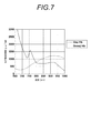
- FIG. 7 shows oxygenated hemoglobin (oxy-Hb combined with oxygen) that is abundant in human arteries and deoxygenated hemoglobin (deoxy-Hb that is not combined with oxygen) that is abundant in veins.
- the molecular absorption coefficient for each light wavelength is shown.
- a light absorber including two substances (substance A and substance B) having different wavelength dependency of light absorption characteristics is irradiated with light having a first wavelength and a second wavelength.
- [CA] is the concentration of substance A
- [CB] is the concentration of substance B
- Ai ⁇ 1 is the absorption coefficient of substance A for light at the first wavelength
- Bi ⁇ 1 is the absorption coefficient of substance B for light of the first wavelength.
- the signal intensity I ⁇ 1 of the photoacoustic signal detected when the light of the first wavelength is irradiated can be expressed by the following equation.
- I ⁇ 1 Ai ⁇ 1 ⁇ [CA] + Bi ⁇ 1 ⁇ [CB]
- the concentration [CA] of the substance A and the concentration [CB] of the substance B can be calculated by solving the simultaneous equations. Specifically, the concentration [CA] of the substance A and the concentration [CB] of the substance B can be calculated by the following equations.
- the distribution of the substance ratio can be imaged by obtaining [CA] and [CB] calculated as described above and assigning a color to the ratio.
- the calculation load increases because the concentration of each substance must be obtained by calculation.
- it is desired that a display relating to the oxygen saturation can be performed by a simple method without obtaining the concentration of each substance by calculation.
- the present invention provides a photoacoustic image generation apparatus and method for generating a photoacoustic image corresponding to a plurality of wavelengths, and a photoacoustic image generation apparatus and method capable of easily displaying an image according to the presence ratio of a substance.
- the purpose is to provide.
- the present invention includes two kinds of substances having light absorptivity, and the light absorption coefficient for the light of the first wavelength and the first wavelength according to the existence ratio of the two kinds of substances. Is generated in the subject due to the light emission after the light of the first wavelength is emitted to the subject including the light absorber whose light absorption coefficient for the light of the different second wavelength changes.
- a first image generating means for generating a first photoacoustic image based on a first photoacoustic signal which is a photoacoustic wave detection signal, and after light having a second wavelength is emitted to the subject;
- a second image generating means for generating a second photoacoustic image based on a second photoacoustic signal which is a detection signal of a photoacoustic wave generated in the subject due to the light emission; Different colors are assigned to the photoacoustic image and the second photoacoustic image, and the first photoacoustic image and the second light are assigned.
- Providing a photoacoustic image generation apparatus characterized by comprising an image synthesis means for displaying the sound image and synthesizes and displays on the screen a.
- the image composition means assigns the first color to the first photoacoustic image and assigns the second color to the second photoacoustic image.
- the image synthesizing unit mixes the first color and the second color at a ratio corresponding to the signal intensity of the first photoacoustic signal and the second photoacoustic signal.
- the first color and the second color are selected from colors that can be displayed independently by any of the plurality of sub-pixels. May be.
- the first color is selected from red, blue, and green that can be displayed independently by any of the sub-pixels.
- the second color can be selected from two colors that are not selected as the first color among red, blue, and green, in which any of the sub-pixels can be displayed independently.
- the present invention includes two kinds of light-absorbing substances, and the light absorption coefficient for the light of the first wavelength and the first wavelength according to the presence ratio of the two kinds of substances. Is generated in the subject due to the light emission after the light of the first wavelength is emitted to the subject including the light absorber whose light absorption coefficient for the light of the different second wavelength changes.
- a first image generating means for generating a first photoacoustic image based on a first photoacoustic signal which is a photoacoustic wave detection signal, and after light having a second wavelength is emitted to the subject;
- a second image generating means for generating a second photoacoustic image based on a second photoacoustic signal which is a detection signal of a photoacoustic wave generated in the subject due to the light emission;
- Difference image generation means for generating a difference image between the photoacoustic image and the second photoacoustic image, and the first photoacoustic
- a photoacoustic image characterized by comprising difference image synthesis means for assigning different colors to an image and a difference image, and synthesizing the first photoacoustic image and the difference image to display on the display screen A generating device is provided.
- the difference image synthesizing unit assigns the first color to the first photoacoustic image and assigns the second color or the third color to the difference image.
- the first color or the second color is selected from among colors that can be displayed independently by any of the three or more sub-pixels.
- a third color may be selected.
- the first color is selected from any one of red, blue, and green in which the sub-pixel can display alone
- the second color is selected from any one of two colors that are not selected as the first color among red, blue, and green, and any one of the sub-pixels can be displayed independently.
- the third color may be a color that is not selected as the first color or the second color among red, blue, and green, and can be displayed by any one of the sub-pixels.
- the difference image synthesis means assigns a second color when the pixel value of the first photoacoustic image is larger than the pixel value of the second photoacoustic image, and the pixel value of the first photoacoustic image is the second When it is smaller than the pixel value of the photoacoustic image, the third color may be assigned.
- a configuration further including a scaling means for multiplying the difference image by a coefficient may be adopted.
- the image synthesizing unit or the difference image synthesizing unit may perform color allocation only for pixels whose pixel values in at least one of the first photoacoustic image and the second photoacoustic image are equal to or greater than a threshold value.
- Adopting a configuration further comprising light emitting means for emitting the first light and the second light to the subject,
- the first light and the second light are light absorbers depending on the abundance ratios of deoxygenated hemoglobin and oxygenated hemoglobin when the subject contains deoxygenated hemoglobin and oxygenated hemoglobin as a light absorber. It is good also as light of the wavelength from which the light absorption coefficient by changes.
- the present invention also includes two kinds of light-absorbing substances, and a second wavelength different from the first wavelength and the light absorption coefficient for the light of the first wavelength according to the presence ratio of the two kinds of substances.
- the detection signal of the photoacoustic wave generated in the subject after the light having the first wavelength is emitted to the subject including the light absorber whose light absorption coefficient changes with respect to the light.
- the first photoacoustic image is generated based on the first photoacoustic signal detected when the light having the first wavelength is emitted, and the light having the second wavelength is emitted.
- a second photoacoustic image is generated based on the detected second photoacoustic signal.
- the light absorber included in the subject includes two kinds of substances having light absorptivity, and the light absorption coefficient and the second wavelength with respect to the light of the first wavelength according to the existence ratio of the two kinds of substances.
- the light absorption coefficient for the light changes.
- movement procedure of a photoacoustic image generation system. 9 is a flowchart showing a procedure for image composition in the second embodiment.
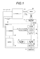
- FIG. 1 shows a photoacoustic image generation system according to a first embodiment of the present invention.
- the photoacoustic image generation system 10 includes an ultrasonic probe (probe) 11, an ultrasonic unit 12, and a laser light source unit 13.
- the laser light source unit 13 is a light source that emits light applied to the subject.
- the laser light source unit 13 is configured, for example, as a Q-switch solid state laser and emits pulsed laser light.
- the laser light source unit 13 emits a pulse laser beam having a first wavelength ( ⁇ 1) and a pulse laser beam having a second wavelength ( ⁇ 2).
- the pulsed laser light emitted from the laser light source unit 13 is guided to the probe 11 using a light guide means such as an optical fiber, and is irradiated from the probe 11 toward the subject.
- the irradiation position of the pulse laser beam is not particularly limited, and the pulse laser beam may be irradiated from a place other than the probe 11.
- ultrasonic waves are generated by absorbing the energy of the pulsed laser light irradiated by the light absorber.
- the subject includes a light absorber including at least two kinds of substances having light absorption properties.
- the light absorber includes, for example, oxygenated hemoglobin and deoxygenated hemoglobin.
- the wavelength dependence of the light absorption coefficient of the two types of substances contained in the light absorber is different from each other. For example, in a certain wavelength range, the light absorption coefficient of the substance A increases as the wavelength increases, and the light absorption coefficient of the substance B decreases as the wavelength increases.
- the light absorption coefficient with respect to the light of the first wavelength and the light absorption coefficient with respect to the light of the second wavelength change according to the proportion of the two kinds of substances contained therein.
- the probe 11 includes an ultrasonic detector.
- the probe 11 has, for example, a plurality of ultrasonic detector elements (ultrasonic transducers) arranged one-dimensionally, and detects photoacoustic waves from within the subject by the one-dimensional arranged ultrasonic transducers. To do.
- the probe 11 outputs a first photoacoustic signal which is a detection signal of a photoacoustic wave generated due to the light irradiation after the subject is irradiated with the light of the first wavelength.
- the probe 11 outputs a second photoacoustic signal which is a detection signal of a photoacoustic wave generated due to the light irradiation after the subject is irradiated with the light of the second wavelength.
- the ultrasonic unit 12 includes a reception circuit 21, an AD conversion unit 22, a reception memory 23, a first image generation unit 24, a second image generation unit 25, an image synthesis unit 26, a trigger control circuit 27, and a control unit 28. Have.
- the ultrasonic unit 12 constitutes a photoacoustic image generation apparatus.
- the receiving circuit 21 receives the photoacoustic signal output from the probe 11.
- the AD conversion means 22 is a detection means, which samples the photoacoustic signal received by the receiving circuit 21 and converts it into digital data.
- the AD conversion means 22 samples the photoacoustic signal at a predetermined sampling period in synchronization with the AD clock signal.
- the AD conversion means 22 stores the sampled photoacoustic signal in the reception memory 23.
- the AD conversion means 22 stores the photoacoustic signal corresponding to each wavelength of the pulsed laser light emitted from the laser light source unit 13 in the reception memory 23.
- the first image generation means 24 generates a first photoacoustic image based on the first photoacoustic signal.
- the second image generation means 25 generates a second photoacoustic image based on the second photoacoustic signal.
- the generation of the photoacoustic image includes processing such as reconstruction of a photoacoustic signal, detection / logarithmic conversion, and the like.
- the pixel value in the generated photoacoustic image corresponds to the signal intensity of the photoacoustic signal detected by the probe 11.
- the image synthesis means 26 synthesizes the first photoacoustic image and the second photoacoustic image.
- the image synthesis in the image synthesis means 26 is performed in two types included in the light absorber based on the first photoacoustic image (first photoacoustic signal) and the second photoacoustic image (second photoacoustic signal). It does not include the process of calculating the concentration of a substance and assigning a color according to the calculated concentration.
- the image synthesizing unit 26 assigns different colors to the first photoacoustic image and the second photoacoustic image at the time of image synthesis.
- the color displayed by each pixel constituting the synthesized image is a color obtained by mixing the color assigned to the first photoacoustic image and the color assigned to the second photoacoustic image.
- the image synthesized by the image synthesizing unit 26 is displayed on the display screen of the image display unit 14 such as a monitor.
- the image composition means 26 assigns a first color to the first photoacoustic image and assigns a second color to the second photoacoustic image, for example.
- each pixel on a display screen of a monitor that performs color display includes a plurality of sub-pixels corresponding to different colors, in other words, a plurality of sub-pixels displaying different colors.
- a plurality of colors corresponding to a plurality of sub-pixels included in each pixel that is, two colors selected from among colors that can be displayed independently by any of the plurality of sub-pixels included in each pixel, the first color and The second color may be used.
- a display screen of a monitor includes one pixel composed of three sub-pixels corresponding to the three primary colors of light, red, blue and green.
- the image composition unit 26 may assign any one of these three colors to the first photoacoustic image and assign one of the remaining two colors to the second photoacoustic image.
- one pixel is composed of sub-pixels of 4 colors or 5 colors in which cyan (light blue) or yellow is added to red, blue and green, 2 colors selected from these 4 colors or 5 colors, It is good also as a 1st color and a 2nd color.
- one pixel may be configured by four subpixels including a subpixel corresponding to red, a subpixel corresponding to blue, and two subpixels corresponding to the same green. Also in this case, any one of the three colors of red, blue, and green that can be displayed by the sub-pixel is assigned to the first photoacoustic image, and one of the remaining two colors is assigned to the second photoacoustic. Assign to an image.
- the first color and the second color can be assigned based on the color corresponding to the subpixel.
- the image synthesizing unit 26 mixes the first color and the second color at a ratio corresponding to the signal intensity of the first photoacoustic signal and the second photoacoustic signal, for example.
- the control means 28 controls each part in the ultrasonic unit 12.
- the trigger control circuit 27 sends a flash lamp trigger signal and a Q switch trigger signal to the laser light source unit 13.
- the laser light source unit 13 receives the flash lamp trigger signal, the laser lamp is turned on to excite the laser medium, and when the Q switch trigger signal is received, the Q switch is turned on to emit pulsed laser light.
- the trigger control circuit 27 outputs a sampling trigger signal (AD trigger signal) to the AD conversion means 22 at the timing when the pulse laser beam is emitted.
- the AD conversion unit 22 starts sampling of the photoacoustic signal based on the sampling trigger signal.
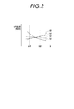
- FIG. 2 shows the relationship between wavelength and light absorption coefficient.
- the horizontal axis represents the wavelength
- the vertical axis represents the light absorption coefficient.
- the light absorption coefficient corresponds to the intensity of the detected photoacoustic signal and the pixel value in the photoacoustic image. It is assumed that the light absorber includes a substance A and a substance B that have light absorptivity.
- the graph (a) shows the wavelength dependence of the light absorption coefficient of the substance A
- the graph (b) shows the wavelength dependence of the light absorption coefficient of the substance B.
- Graph (c) shows the wavelength dependence of the photoacoustic signal detected from the light absorber when the light absorber contains the substance A and the substance B at substantially the same ratio.
- the signal intensity of the photoacoustic signal detected at the wavelength ⁇ 1 includes only the signal intensity and the substance B when only the substance A is included. It becomes an intermediate value of the signal intensity when it is included.
- the signal intensity of the photoacoustic signal detected at the wavelength ⁇ 2 is also an intermediate value between the signal intensity when only the substance A is included and the signal intensity when only the substance B is included.
- the graph (d) shows the wavelength dependence of the photoacoustic signal detected from the light absorber when the concentration of the substance B contained in the light absorber is sufficiently higher than the concentration of the substance A.
- the concentration of the substance B contained in the light absorber is sufficiently higher than the concentration of the substance A
- the signal intensity of the photoacoustic signal detected at the wavelength ⁇ 1 is higher than the signal intensity when the substance B is included. A little higher value.
- the signal intensity of the photoacoustic signal detected at the wavelength ⁇ 2 is slightly lower than the signal intensity when only the substance B is included.
- the signal intensity obtained has a wavelength dependence close to the graph (a) if the substance A is close to 100%, and the substance B is If it is close to 100%, it has a wavelength dependence close to that of graph (b). Therefore, when different colors are assigned to the first photoacoustic image and the second photoacoustic image for display, the hue changes in an analog manner according to the signal intensity ratio between the first wavelength and the second wavelength. It is possible to display a moving image. For example, when blue is assigned to the first photoacoustic image and red is assigned to the second photoacoustic image, an image whose hue changes between red and blue according to the presence ratio of the substance A and the substance B is obtained.
- FIG. 3 shows a color change in an image obtained by synthesizing the first photoacoustic image and the second photoacoustic image.
- the vertical axis represents the pixel value of the second photoacoustic image
- the horizontal axis represents the pixel value of the first photoacoustic image.
- the first wavelength is 750 nm
- the second wavelength is 800 nm.
- Blue is assigned to the first photoacoustic image corresponding to irradiation with light having a wavelength of 750 nm
- red is assigned to the second photoacoustic image corresponding to irradiation with light having a wavelength of 800 nm.
- the hue changes between blue and red according to the angle ⁇ shown in FIG.
- the color of the pixel of the synthesized image becomes reddish.
- the color assignment is arbitrary, and by assigning two colors having different hues to the first photoacoustic image and the second photoacoustic image, an image in which the hue changes between the two colors is obtained.
- the signal intensity of the detected photoacoustic signal is weak, the influence of noise or the like becomes relatively large, and the signal intensity fluctuates relatively greatly due to variations in noise or the like. In that case, it is conceivable that the hue varies greatly from pixel to pixel and is displayed in a multicolored mosaic pattern, making it difficult to see.
- the signal intensity may be subjected to threshold processing, and if it is smaller than a certain signal intensity, it may be excluded from the calculation target for color display. That is, the image composition unit may perform color assignment only for pixels whose pixel values in at least one of the first photoacoustic image and the second photoacoustic image are equal to or greater than a threshold value.
- FIG. 4 shows an operation procedure of the photoacoustic image generation system.
- the trigger control circuit 27 sends a flash lamp trigger signal to the laser light source unit 13 and then sends a Q switch trigger signal.
- the laser light source unit 13 turns on the flash lamp in response to the flash lamp trigger signal, turns on the Q switch in response to the Q switch trigger signal, and emits pulsed laser light having the first wavelength (step S1).
- a photoacoustic wave is generated by absorbing the energy of the pulse laser beam irradiated by the light absorber.
- the probe 11 detects the first photoacoustic wave generated in the subject (step S2).
- the detected first photoacoustic wave is sampled by the AD conversion means 22 via the reception circuit 21, and the first photoacoustic signal is stored in the reception memory 23.
- the first image generation means 24 reads the first photoacoustic signal from the reception memory 23, and generates a first photoacoustic image based on the read first photoacoustic signal (step S3).
- the trigger control circuit 27 sends a flash lamp trigger signal and a Q switch trigger signal to the laser light source unit 13.
- the laser light source unit 13 turns on the flash lamp in response to the flash lamp trigger signal, turns on the Q switch in response to the Q switch trigger signal, and emits a pulsed laser beam having the second wavelength (step S4).
- a photoacoustic wave is generated by absorbing the energy of the pulse laser beam irradiated by the light absorber.
- the probe 11 detects the second photoacoustic wave generated in the subject (step S5).
- the detected second photoacoustic wave is sampled by the AD conversion means 22 via the reception circuit 21, and the second photoacoustic signal is stored in the reception memory 23.
- the second image generation means 25 reads the second photoacoustic signal from the reception memory 23 and generates a second photoacoustic image based on the read second photoacoustic signal (step S6).
- the region irradiated with the laser beam of the subject may be divided into a plurality of partial regions, and light irradiation and photoacoustic signal detection may be performed for each partial region.
- the image composition means 26 assigns the first color to the first photoacoustic image (step S7) and assigns the second color to the second photoacoustic image (step S8).
- the image synthesizing unit 26 synthesizes the first photoacoustic image assigned the first color and the second photoacoustic image assigned the second color (step S9).
- the synthesized image is displayed on the image display means 14.
- pixels of a color image are represented by (R, G, B) (R, G, B are intensities of red, blue, and green, respectively).
- the pixel value (signal intensity) in the first photoacoustic image is I ⁇ 1
- the pixel value of the image in which the first photoacoustic image is assigned to blue can be expressed as (0, 0, I ⁇ 1).
- the pixel value (signal intensity) in the second photoacoustic image is I ⁇ 2
- the pixel value of the image in which the second photoacoustic image is assigned to red can be represented by (I ⁇ 2, 0, 0).
- a pixel value of an image obtained by combining them is represented by (I ⁇ 2, 0, I ⁇ 1).
- the first photoacoustic image is generated based on the first photoacoustic signal detected when the light of the first wavelength is irradiated, and is detected when the light of the second wavelength is irradiated.
- a second photoacoustic image is generated based on the second photoacoustic signal.
- the light absorber included in the subject includes two kinds of substances having light absorptivity, and the light absorption coefficient and the second wavelength with respect to the light of the first wavelength according to the existence ratio of the two kinds of substances. The light absorption coefficient for the light changes.
- an image corresponding to the proportion of the two types of substances contained in the light absorber is displayed.
- an image related to oxygen saturation can be displayed without calculating oxygen saturation.
- the image synthesis unit 26 assigns different colors to the first photoacoustic image and the second photoacoustic image.
- a difference image between the first photoacoustic image and the second photoacoustic image is generated, and the first photoacoustic image or the second photoacoustic image and the difference image are generated. Assign different colors to each other.
- the image composition unit 26 in the second embodiment has a difference image generation function for generating such a difference image.
- the image synthesizing means 26 in the second embodiment mobile phone instead of synthesizing and displaying the first photoacoustic image and the second photoacoustic image on the display screen, the first photoacoustic image or the first photoacoustic image. 2 has a differential image synthesis function for synthesizing the photoacoustic image 2 and the differential image and displaying them on the display screen.
- synthesize combines a 1st photoacoustic image and a difference image is demonstrated.
- the image composition unit 26 assigns, for example, a first color to the first photoacoustic image and assigns a second color or a third color to the difference image.
- any one of the three or more subpixels is selected from three or more colors that can be displayed independently.
- the first color, the second color, and the third color may be used.
- the image composing unit 26 sets one of the three primary colors of light, red, blue, and green as a first color, one of the remaining two as a second color, and the other one as a third color. Color. Specifically, green can be the first color, the second color can be blue, and the third color can be red.
- the first photoacoustic image, the second photoacoustic image, and the difference are based on the colors corresponding to the subpixels.
- a first color, a second color, and a third color can be assigned to the image, respectively.
- assigning the first color to the first photoacoustic image and assigning the second color or the third color to the difference image that is, when only two colors are required for color assignment, The pixel only needs to have at least two subpixels corresponding to different colors.
- the image composition unit 26 assigns the second color or the third color according to, for example, the difference between the first photoacoustic image and the second photoacoustic image. For example, when the pixel value of the first photoacoustic image is larger than the pixel value of the second photoacoustic image (I ⁇ 1> I ⁇ 2), the image composition unit assigns a second color to the difference image. On the other hand, when the pixel value of the first photoacoustic image is smaller than the pixel value of the second photoacoustic image (I ⁇ 1 ⁇ I ⁇ 2), the third color is assigned to the difference image. Scaling may be performed by multiplying the difference image by a predetermined coefficient, and color may be assigned to the difference image after scaling.
- the substances contained in the light absorber are a substance A having a wavelength dependency shown in the graph (a) in FIG. 2 and a substance B having a wavelength dependency shown in the graph (b) in the light absorption coefficient.
- the first wavelength ( ⁇ 1) the light absorption coefficient of the substance A is higher than the light absorption coefficient of the substance B
- the second wavelength ( ⁇ 2) the light absorption coefficient of the substance B is higher than the light absorption coefficient of the substance A.
- the signal intensity of the first photoacoustic signal pixel value of the first photoacoustic image
- the second photoacoustic signal second Higher than the pixel value of the photoacoustic image.
- the signal intensity of the first photoacoustic signal is lower than the signal intensity of the second photoacoustic signal. Therefore, by taking the difference between the first photoacoustic image and the second photoacoustic image and examining the positive / negative, it is possible to determine which material is relatively contained.
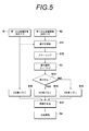
- FIG. 5 shows an image composition procedure.
- the image synthesizing unit 26 calculates the difference between the first photoacoustic image 51 and the second photoacoustic image 52 (step S11).
- the image synthesis unit 26 subtracts the pixel value of the second photoacoustic image 52 from the pixel value of the first photoacoustic image 51, for example.
- the image composition means 26 multiplies the calculated difference by a predetermined coefficient (step S12).
- the coefficient to be multiplied by the difference may be determined according to the measurement range of the oxygen saturation, the part information in the subject, the disease information, and the like. By scaling by a coefficient, for example, it becomes easy to observe a change in substance concentration in a range where the difference is small.
- the image composition unit 26 determines whether or not the difference is positive in the scaled difference image 53 (step S13). If the difference is positive, that is, if the pixel value in the first photoacoustic image 51 is larger than the pixel value in the second photoacoustic image 52, the image composition unit 26 assigns blue to the difference image 53 (Ste S14). When the difference is negative, that is, when the pixel value in the first photoacoustic image 51 is smaller than the pixel value in the second photoacoustic image 52, red is assigned to the difference image 53 (step S15).
- the image composition means 26 assigns green to the first photoacoustic image 51 (step S16).
- the image synthesizing unit 26 synthesizes the first photoacoustic image 51 assigned with green and the difference image 53 assigned with blue or red to generate a synthesized image 54 (step S17).
- the composite image 54 is displayed on the image display means 14.
- a color bar that changes between the second color and the third color is displayed, and a numerical value that is a measure of the relationship with the oxygen saturation range is displayed next to the color bar. Also good.
- the reference numerical value may be changed according to the coefficient at the time of scaling.
- FIG. 6 shows colors in an image obtained by combining the first photoacoustic image and the difference image. It is assumed that the first wavelength is 750 nm and the second wavelength is 800 nm. Green is assigned to the first photoacoustic image corresponding to irradiation with light having a wavelength of 750 nm.
- Green is assigned to the first photoacoustic image corresponding to irradiation with light having a wavelength of 750 nm.
- red is assigned to a range where the difference is positive
- blue is assigned to a range where the difference is negative.
- the difference between the first photoacoustic image and the second photoacoustic image is small, the change in hue becomes small and it becomes difficult to determine the oxygen saturation and the like.
- the difference is multiplied by a coefficient larger than 1 to expand (scaling) the difference as indicated by the dotted arrow in FIG. It is sufficient to assign blue or red to each other.
- scaling for example, an image display related to a specific range of oxygen saturation can be performed.
- threshold processing is performed on at least one of the pixel value of the first photoacoustic image and the pixel value of the second photoacoustic image, and the first photoacoustic image and the second photoacoustic image are processed.
- Colors may be assigned to pixels whose pixel value is at least a threshold value in at least one of the above.
- the photoacoustic image generation apparatus and method of the present invention are not limited to the above embodiment, and various modifications can be made from the configuration of the above embodiment. Further, modifications and changes are also included in the scope of the present invention.
Landscapes
- Health & Medical Sciences (AREA)
- Life Sciences & Earth Sciences (AREA)
- Physics & Mathematics (AREA)
- Biomedical Technology (AREA)
- Medical Informatics (AREA)
- Biophysics (AREA)
- Pathology (AREA)
- Engineering & Computer Science (AREA)
- Veterinary Medicine (AREA)
- Heart & Thoracic Surgery (AREA)
- Public Health (AREA)
- Molecular Biology (AREA)
- Surgery (AREA)
- Animal Behavior & Ethology (AREA)
- General Health & Medical Sciences (AREA)
- Optics & Photonics (AREA)
- Spectroscopy & Molecular Physics (AREA)
- Acoustics & Sound (AREA)
- Ultra Sonic Daignosis Equipment (AREA)
Abstract
本発明は、物質の存在割合に応じた画像を簡易に表示可能な光音響画像生成装置及び方法を提供する。被検体は、光吸収性を有する物質を2種類含む。光吸収体は、含まれる2種類の物質の存在割合に応じて、第1の波長の光に対する光吸収係数と第2の波長の光に対する光吸収係数とが変化する。第1の画像生成手段24は、第1の波長の光が出射されたときの第1の光音響信号に基づいて第1の光音響画像を生成する。第2の画像生成手段25は、第2の波長の光が出射されたときの第2の光音響信号に基づいて第2の光音響画像を生成する。画像合成手段26は、第1の光音響画像と第2の光音響画像とに互いに異なる色を割り当て、第1の光音響画像と第2の光音響画像とを合成して表示画面上に表示させる。
Description
本発明は、光音響画像生成装置及び方法に関し、光照射に起因して生じた光音響波に基づいて光音響画像を生成する光音響画像生成装置及び方法に関する。
従来、例えば特許文献1や非特許文献1に示されているように、光音響効果を利用して生体の内部を画像化する光音響画像化装置が知られている。この光音響画像化装置においては、例えばパルスレーザ光等のパルス光が生体に照射される。このパルス光の照射を受けた生体内部では、パルス光のエネルギーを吸収した生体組織が熱によって体積膨張し、音響波が発生する。光音響画像化装置は、この音響波を超音波プローブなどで検出し、検出された信号(光音響信号)に基づいて生体内部を可視像化することが可能である。光音響画像化方法では、特定の光吸収体において音響波が発生するため、生体における特定の組織、例えば血管等を画像化することができる。
ところで、生体組織の多くは光吸収特性が光の波長に応じて変わり、また一般に、その光吸収特性も組織ごとに特有のものとなっている。例えば図7に、ヒトの動脈に多く含まれる酸素化ヘモグロビン(酸素と結合したヘモグロビン:oxy-Hb)と、静脈に多く含まれる脱酸素化ヘモグロビン(酸素と結合していないヘモグロビンdeoxy-Hb)の光波長ごとの分子吸収係数を示す。このような吸収特性の違いを利用することにより、生体内中の酸化ヘモグロビンと脱酸素化ヘモグロビンを分離して定量化することが可能である(例えば特許文献2参照)。また、酸素化ヘモグロビンと脱酸素化ヘモグロビンの量を割り出し、酸素飽和度を計算することができる(例えば特許文献3参照)。
A High-Speed Photoacoustic Tomography System based on a Commercial Ultrasound and a Custom Transducer Array, Xueding Wang, Jonathan Cannata,Derek DeBusschere, Changhong Hu, J. Brian Fowlkes, and Paul Carson, Proc. SPIE Vol. 7564, 756424 (Feb.23, 2010)
例えば、光吸収特性の波長依存性が異なる2つの物質(物質A、物質B)が含まれる光吸収体に、第1の波長及び第2の波長の光を照射することを考える。[CA]を物質Aの濃度、[CB]を物質Bの濃度とし、Aiλ1を第1の波長に光に対する物質Aの吸収係数、Biλ1を第1の波長の光に対する物質Bの吸収係数とすると、第1の波長の光が照射されたときに検出される光音響信号の信号強度Iλ1は、下記式で表わすことができる。
Iλ1=Aiλ1×[CA]+Biλ1×[CB]
Iλ1=Aiλ1×[CA]+Biλ1×[CB]
また、Aiλ2を第2の波長の光に対する物質Aの吸収係数、Biλ2を第2の波長の光に対する物質Bの吸収係数とすると、第2の波長の光が照射されたときに検出される光音響信号の信号強度Iλ2は、下記式で表わすことができる。
Iλ2=Aiλ2×[CA]+Biλ2×[CB]
物質A及び物質Bの各波長における光吸収係数が既知であれば、連立方程式を解くことにより、物質Aの濃度[CA]と物質Bの濃度[CB]とを計算することができる。具体的には、下記式により、物質Aの濃度[CA]及び物質Bの濃度[CB]を計算することができる。

Iλ2=Aiλ2×[CA]+Biλ2×[CB]
物質A及び物質Bの各波長における光吸収係数が既知であれば、連立方程式を解くことにより、物質Aの濃度[CA]と物質Bの濃度[CB]とを計算することができる。具体的には、下記式により、物質Aの濃度[CA]及び物質Bの濃度[CB]を計算することができる。
上記のようにして計算した[CA]と[CB]を求め、その比に対して色を割り当てることで、物質の比率の分布を画像化することができる。しかしながら、その場合、計算により各物質の濃度を求めなければならないため、計算負荷が高くなる。例えば酸素飽和度の分布を画像化したい場合に、正確な酸素飽和度の値を求めることまでは必要なく、酸素化ヘモグロビンと脱酸素化ヘモグロビンの分布又は相対分布がわかればよいという場合もある。そのような場合、計算により各物質の濃度を求めなくても、簡易な方法で酸素飽和度に関連した表示ができることが望まれる。
本発明は、上記に鑑み、複数の波長に対応した光音響画像を生成する光音響画像生成装置及び方法において、物質の存在割合に応じた画像を簡易に表示可能な光音響画像生成装置及び方法を提供することを目的とする。
上記目的を達成するために、本発明は、光吸収性を有する物質を2種類含み、2種類の物質の存在割合に応じて、第1の波長の光に対する光吸収係数と第1の波長とは異なる第2の波長の光に対する光吸収係数とが変化する光吸収体を含む被検体に対して第1の波長の光が出射された後にその光出射に起因して被検体内で発生した光音響波の検出信号である第1の光音響信号に基づいて第1の光音響画像を生成する第1の画像生成手段と、被検体に対して第2の波長の光が出射された後にその光出射に起因して被検体内で発生した光音響波の検出信号である第2の光音響信号に基づいて第2の光音響画像を生成する第2の画像生成手段と、第1の光音響画像と第2の光音響画像とに互いに異なる色を割り当て、第1の光音響画像と第2の光音響画像とを合成して表示画面上に表示させる画像合成手段とを備えたことを特徴とする光音響画像生成装置を提供する。
本発明では、画像合成手段が、第1の光音響画像に第1の色を割り当て、かつ第2の光音響画像に第2の色を割り当てる構成を採用できる。
上記の場合、画像合成手段が、第1の光音響信号及び第2の光音響信号の信号強度に応じた比率で第1の色と第2の色とを混色することが好ましい。
表示画面における各画素が、それぞれ異なる色に対応した複数のサブ画素を含むとき、複数のサブ画素の何れかが単独で表示可能な色の中から、第1の色及び第2の色を選択してもよい。例えば表示画面における各画素が赤、青及び緑に対応したサブ画素を含むとき、第1の色を、それらサブ画素の何れかが単独で表示可能な、赤、青及び緑の中から選択し、第2の色を、それらサブ画素の何れかが単独で表示可能な、赤、青及び緑のうち、第1の色として選択されていない2つの色の中から選択することができる。
上記目的を達成するために、本発明は、 光吸収性を有する物質を2種類含み、2種類の物質の存在割合に応じて、第1の波長の光に対する光吸収係数と第1の波長とは異なる第2の波長の光に対する光吸収係数とが変化する光吸収体を含む被検体に対して第1の波長の光が出射された後にその光出射に起因して被検体内で発生した光音響波の検出信号である第1の光音響信号に基づいて第1の光音響画像を生成する第1の画像生成手段と、被検体に対して第2の波長の光が出射された後にその光出射に起因して被検体内で発生した光音響波の検出信号である第2の光音響信号に基づいて第2の光音響画像を生成する第2の画像生成手段と、第1の光音響画像と第2の光音響画像との差分画像を生成する差分画像生成手段と、第1の光音響画像と、差分画像とに互いに異なる色を割り当て、第1の光音響画像と、差分画像とを合成して表示画面上に表示させる差分画像合成手段とを備えたことを特徴とする光音響画像生成装置を提供する。
上記の場合、差分画像合成手段が、第1の光音響画像に第1の色を割り当て、かつ差分画像に第2の色又は第3の色を割り当てる構成を採用できる。
表示画面における各画素が、それぞれ異なる色に対応した3以上のサブ画素を含むとき、3以上のサブ画素の何れかが単独で表示可能な色の中から、第1の色、第2の色、及び第3の色を選択してもよい。例えば、表示画面における各画素が赤、青及び緑に対応したサブ画素を含むとき、第1の色をサブ画素が単独で表示可能な、赤、青及び緑のうちの何れかから選択された色とし、第2の色を、サブ画素の何れかが単独で表示可能な、赤、青及び緑のうち、第1の色として選択されていない2つの色のうちの何れかから選択された色とし、第3の色を、前記サブ画素の何れかが単独で表示可能な、赤、青及び緑のうち第1の色及び第2の色として選択されていない1つの色としてもよい。
差分画像合成手段が、第1の光音響画像の画素値が第2の光音響画像の画素値よりも大きいときは第2の色を割り当て、第1の光音響画像の画素値が第2の光音響画像の画素値よりも小さいときは第3の色を割り当ててもよい。
差分画像に係数を乗じるスケーリング手段を更に備えた構成を採用してもよい。
画像合成手段又は差分画像合成手段は、第1の光音響画像及び第2の光音響画像の少なくとも一方における画素値がしきい値以上の画素についてのみ色の割り当てを行ってもよい。
第1の光及び前記第2の光を前記被検体へ出射する光出射手段を更に備えた構成を採用し、
第1の光及び第2の光は、光吸収体として被検体に脱酸素化ヘモグロビン及び酸素化ヘモグロビンが含まれる場合に、脱酸素化ヘモグロビン及び酸素化ヘモグロビンの存在割合に応じて、光吸収体による光吸収係数が変化する波長の光としてもよい。
第1の光及び第2の光は、光吸収体として被検体に脱酸素化ヘモグロビン及び酸素化ヘモグロビンが含まれる場合に、脱酸素化ヘモグロビン及び酸素化ヘモグロビンの存在割合に応じて、光吸収体による光吸収係数が変化する波長の光としてもよい。
本発明は、また、光吸収性を有する物質を2種類含み、2種類の物質の存在割合に応じて、第1の波長の光に対する光吸収係数と第1の波長とは異なる第2の波長の光に対する光吸収係数とが変化する光吸収体を含む被検体に対して第1の波長の光が出射された後にその光出射に起因して被検体内で発生した光音響波の検出信号である第1の光音響信号に基づいて第1の光音響画像を生成するステップと、被検体に対して第2の波長の光が出射された後にその光出射に起因して被検体内で発生した光音響波の検出信号である第2の光音響信号に基づいて第2の光音響画像を生成するステップと、第1の光音響画像と第2の光音響画像とに互いに異なる色を割り当て、第1の光音響画像と第2の光音響画像とを合成して表示画面上に表示させるステップとを有することを特徴とする光音響画像生成方法を提供する。
本発明では、第1の波長の光が出射されたときに検出された第1の光音響信号に基づいて第1の光音響画像を生成し、第2の波長の光が出射されたときに検出された第2の光音響信号に基づいて第2の光音響画像を生成する。被検体に含まれる光吸収体は、光吸収性を有する物質を2種類含んでおり、それら2種類の物質の存在割合に応じて、第1の波長の光に対する光吸収係数と第2の波長の光に対する光吸収係数とが変化する。第1の光音響画像と第2の光音響画像とに異なる色を割り当て、それらを合成して表示することで、光吸収体に含まれる2種類の物質の存在割合に応じた画像を表示することができる。
以下、図面を参照し、本発明の実施の形態を詳細に説明する。図1は、本発明の第1実施形態の光音響画像生成システムを示す。光音響画像生成システム10は、超音波探触子(プローブ)11と、超音波ユニット12と、レーザ光源ユニット13とを備える。レーザ光源ユニット13は、被検体に照射される光を出射する光源である。レーザ光源ユニット13は、例えばQスイッチ固体レーザとして構成され、パルスレーザ光を出射する。レーザ光源ユニット13は、第1の波長(λ1)のパルスレーザ光と第2の波長(λ2)のパルスレーザ光とを出射する。
レーザ光源ユニット13から出射したパルスレーザ光は、例えば光ファイバなどの導光手段を用いてプローブ11まで導光され、プローブ11から被検体に向けて照射される。パルスレーザ光の照射位置は特に限定されず、プローブ11以外の場所からパルスレーザ光の照射を行ってもよい。
被検体内では、光吸収体が照射されたパルスレーザ光のエネルギーを吸収することで超音波(音響波)が生じる。被検体には、光吸収性を有する物質を少なくとも2種類含む光吸収体が含まれる。光吸収体は、例えば酸素化ヘモグロビンと脱酸素化ヘモグロビンとを含む。光吸収体に含まれる2種類の物質の光吸収係数の波長依存性は互いに異なる。例えばある波長範囲で、物質Aは波長が長くなるに連れて光吸収係数が大きくなり、物質Bは波長が長くなるに連れて光吸収係数が小さくなる。光吸収体は、それに含まれる2種類の物質の存在割合に応じて、第1の波長の光に対する光吸収係数と第2の波長の光に対する光吸収係数とが変化する。
プローブ11は、超音波検出器を含む。プローブ11は、例えば一次元的に配列された複数の超音波検出器素子(超音波振動子)を有し、その一次元配列された超音波振動子により被検体内からの光音響波を検出する。プローブ11は、第1の波長の光が被検体に照射された後に、その光照射に起因して発生した光音響波の検出信号である第1の光音響信号を出力する。また、プローブ11は、第2の波長の光が被検体に照射された後に、その光照射に起因して発生した光音響波の検出信号である第2の光音響信号を出力する。
超音波ユニット12は、受信回路21、AD変換手段22、受信メモリ23、第1の画像生成手段24、第2の画像生成手段25、画像合成手段26、トリガ制御回路27、及び制御手段28を有する。超音波ユニット12は、光音響画像生成装置を構成する。
受信回路21は、プローブ11が出力した光音響信号を受信する。AD変換手段22は検出手段であり、受信回路21が受信した光音響信号をサンプリングし、デジタルデータに変換する。AD変換手段22は、ADクロック信号に同期して、所定のサンプリング周期で光音響信号のサンプリングを行う。AD変換手段22は、サンプリングした光音響信号を受信メモリ23に格納する。AD変換手段22は、レーザ光源ユニット13から出射されるパルスレーザ光の各波長に対応した光音響信号を受信メモリ23に格納する。
第1の画像生成手段24は、第1の光音響信号に基づいて第1の光音響画像を生成する。第2の画像生成手段25は、第2の光音響信号に基づいて第2の光音響画像を生成する。光音響画像の生成は、例えば光音響信号の再構成、検波・対数変換などの処理を含む。生成された光音響画像における画素値は、プローブ11で検出された光音響信号の信号強度に対応する。
画像合成手段26は、第1の光音響画像と第2の光音響画像とを合成する。画像合成手段26における画像合成は、第1の光音響画像(第1の光音響信号)と第2の光音響画像(第2の光音響信号)に基づいて光吸収体に含まれる2種類の物質の濃度を計算し、計算で求めた濃度に応じて色を割り当てる処理を含まない。画像合成手段26は、画像合成に際して、第1の光音響画像と第2の光音響画像とに互いに異なる色を割り当てる。合成された画像を構成する各画素が表示する色は、第1の光音響画像に割り当てられた色と、第2の光音響画像に割り当てられた色とが混色した色となる。画像合成手段26で合成された画像は、モニタなどの画像表示手段14の表示画面上に表示される。
画像合成手段26は、例えば第1の光音響画像に第1の色を割り当て、かつ第2の光音響画像に第2の色を割り当てる。通常、カラー表示を行うモニタの表示画面における各画素は、それぞれ異なる色に対応した複数のサブ画素、換言すれば、それぞれ異なる色を表示する複数のサブ画素を含んでいる。各画素に含まれる複数のサブ画素に対応した複数の色、すなわち、各画素に含まれる複数のサブ画素の何れかが単独で表示可能な色から選択された2色を、第1の色及び第2の色としてもよい。例えば、一般にモニタの表示画面は、光の三原色である赤、青及び緑に対応した3つのサブ画素で1つの画素が構成されている。この場合、画像合成手段26は、こられ3色のうちの何れか1つを第1の光音響画像に割り当て、残り2色のうちの1つを第2の光音響画像に割り当ててもよい。1つの画素が、赤、青及び緑に、シアン(水色)や黄色を加えた4色又は5色のサブ画素で構成される場合は、それら4色又は5色から選択された2色を、第1の色及び第2の色としてもよい。なお、必ずしも1つの画素に含まれる全てのサブ画素が互いに異なる色に対応する必要はなく、それらのサブ画素に加えて、それらのサブ画素のいずれかと同一の色に対応したサブ画素を1つの画素に含ませてもよい。例えば、赤に対応したサブ画素、青に対応したサブ画素、及び同一の緑に対応した2つのサブ画素からなる4つのサブ画素により1つの画素を構成してもよい。この場合も、サブ画素が表示可能な、赤、青及び緑の3色のうちの何れか1つを第1の光音響画像に割り当て、残り2色のうちの1つを第2の光音響画像に割り当てればよい。すなわち、1つの画素が、それぞれ異なる色に対応した少なくとも2つのサブ画素を有していれば、サブ画素が対応する色に基づき第1の色及び第2の色を割り当てることができる。画像合成手段26は、例えば第1の光音響信号及び第2の光音響信号の信号強度に応じた比率で第1の色と第2の色とを混色する。
制御手段28は、超音波ユニット12内の各部の制御を行う。トリガ制御回路27は、レーザ光源ユニット13に対して、フラッシュランプトリガ信号及びQスイッチトリガ信号を送る。レーザ光源ユニット13は、フラッシュランプトリガ信号を受けるとフラッシュランプを点灯してレーザ媒質を励起し、Qスイッチトリガ信号を受けるとQスイッチをオンにしてパルスレーザ光を出射する。また、トリガ制御回路27は、パルスレーザ光が出射するタイミングでAD変換手段22にサンプリングトリガ信号(ADトリガ信号)を出力する。AD変換手段22は、サンプリングトリガ信号に基づいて光音響信号のサンプリングを開始する。
図2は、波長と光吸収係数との関係を示す。横軸は波長を表し、縦軸は光吸収係数を表す。光吸収係数は、検出される光音響信号の強度及び光音響画像における画素値に対応する。光吸収体には、光吸収性を有する物質Aと物質Bとが含まれているとする。図2において、グラフ(a)は物質Aの光吸収係数の波長依存性を示し、グラフ(b)は物質Bの光吸収係数の波長依存性を示す。
グラフ(c)は、光吸収体が物質Aと物質Bとをほぼ同じ割合で含む場合に、その光吸収体から検出される光音響信号の波長依存性を示す。光吸収体が物質Aと物質Bとをほぼ同じ割合で含む場合、波長λ1のときに検出される光音響信号の信号強度は、物質Aのみを含むとした場合の信号強度と物質Bのみを含むとした場合の信号強度の中間の値となる。波長λ2のときに検出される光音響信号の信号強度も、物質Aのみを含むとした場合の信号強度と物質Bのみを含むとした場合の信号強度の中間の値となる。
一方、グラフ(d)は、光吸収体に含まれる物質Bの濃度が物質Aの濃度よりも十分に高いとき、その光吸収体から検出される光音響信号の波長依存性を示す。光吸収体に含まれる物質Bの濃度が物質Aの濃度よりも十分に高い場合、波長λ1のときに検出される光音響信号の信号強度は、物質Bを含むとした場合の信号強度よりも少し高い値となる。また、波長λ2のときに検出される光音響信号の信号強度は、物質Bのみを含むとした場合の信号強度よりも少し低い値となる。
光吸収体に含まれる物質Aと物質Bの和が一定であるとすれば、得られる信号強度は、物質Aが100%に近ければグラフ(a)に近い波長依存性を持ち、物質Bが100%に近ければグラフ(b)に近い波長依存性を持つ。そこで、第1の光音響画像と第2の光音響画像とに異なる色を割り当てて表示すると、第1の波長と第2の波長での信号強度比に応じて、アナログ的に色相が変化していく画像を表示することが可能である。例えば第1の光音響画像に青を割り当て第2の光音響画像に赤を割り当てると、物質Aと物質Bの存在割合に応じて赤色と青色との間で色相が変化する画像が得られる。
図3に、第1の光音響画像と第2の光音響画像とを合成した画像における色の変化を示す。縦軸は第2の光音響画像の画素値を表し、横軸は第1の光音響画像の画素値を表す。第1の波長は750nmで、第2の波長は800nmであったとする。波長750nmの光を照射したときに対応した第1の光音響画像に対しては青を割り当て、波長800nmの光を照射したときに対応した第2の光音響画像に対しては赤を割り当てる。合成された画像では、図2中に示す角度θに応じて青から赤の間で色相が変化する。例えば第2の光音響画像の画素値が第1の光音響画像の画素値よりも大きければ、合成された画像の画素における色は赤みが強くなる。色の割り当ては任意であり、色相が異なる2つの色を第1の光音響画像と第2の光音響画像とに割り当てることで、2つの色の間で色相が変化する画像が得られる。
なお、検出される光音響信号の信号強度が弱い場合、ノイズ等の影響が相対的に大きくなり、ノイズ等のばらつきによって信号強度が相対的に大きく変動する。その場合、画素ごとに色相が大きく変動し、多色のモザイク状に表示されて見にくくなることが考えられる。そのような事態を避けるために、信号強度をしきい値処理し、一定の信号強度より小さい場合はカラー表示の演算対象から除外してもよい。つまり、画像合成手段にて、第1の光音響画像及び第2の光音響画像の少なくとも一方における画素値がしきい値以上の画素についてのみ色の割り当てを行うようにしてもよい。
図4は、光音響画像生成システムの動作手順を示す。トリガ制御回路27は、レーザ光源ユニット13にフラッシュランプトリガ信号を送り、次いで、Qスイッチトリガ信号を送る。レーザ光源ユニット13は、フラッシュランプトリガ信号に応答してフラッシュランプを点灯し、Qスイッチトリガ信号に応答してQスイッチをオンにし、第1の波長のパルスレーザ光を出射する(ステップS1)。
被検体内では、光吸収体が照射されたパルスレーザ光のエネルギーを吸収することで、光音響波が発生する。プローブ11は、被検体内で発生した第1の光音響波を検出する(ステップS2)。検出された第1の光音響波は、受信回路21を経てAD変換手段22でサンプリングされ、第1の光音響信号が受信メモリ23に格納される。第1の画像生成手段24は、受信メモリ23から第1の光音響信号を読み出し、読み出した第1の光音響信号に基づいて第1の光音響画像を生成する(ステップS3)。
続いて、トリガ制御回路27は、レーザ光源ユニット13にフラッシュランプトリガ信号とQスイッチトリガ信号とを送る。レーザ光源ユニット13は、フラッシュランプトリガ信号に応答してフラッシュランプを点灯し、Qスイッチトリガ信号に応答してQスイッチをオンにし、第2の波長のパルスレーザ光を出射する(ステップS4)。
被検体内では、光吸収体が照射されたパルスレーザ光のエネルギーを吸収することで、光音響波が発生する。プローブ11は、被検体内で発生した第2の光音響波を検出する(ステップS5)。検出された第2の光音響波は、受信回路21を経てAD変換手段22でサンプリングされ、第2の光音響信号が受信メモリ23に格納される。第2の画像生成手段25は、受信メモリ23から第2の光音響信号を読み出し、読み出した第2の光音響信号に基づいて第2の光音響画像を生成する(ステップS6)。なお、被検体のレーザ光が照射される領域を複数の部分領域に分割し、部分領域ごとに光照射と光音響信号の検出とを行ってもよい。
画像合成手段26は、第1の光音響画像に第1の色を割り当て(ステップS7)、第2の光音響画像に第2の色を割り当てる(ステップS8)。画像合成手段26は、第1の色を割り当てた第1の光音響画像と、第2の色を割り当てた第2の光音響画像とを合成する(ステップS9)。合成された画像は、画像表示手段14に表示される。
例えばカラー画像の画素を(R,G,B)(R、G、Bはそれぞれ赤、青、緑の強度)で表現する。第1の光音響画像における画素値(信号強度)をIλ1としたとき、第1の光音響画像を青に割り当てた画像の画素値は(0,0,Iλ1)と表すことができる。また、第2の光音響画像における画素値(信号強度)をIλ2としたとき、第2の光音響画像を赤に割り当てた画像の画素値は(Iλ2,0,0)で表わすことができる。それらを合成した画像の画素値は、(Iλ2,0,Iλ1)で表わされる。
本実施形態では、第1の波長の光を照射したときに検出された第1の光音響信号に基づいて第1の光音響画像を生成し、第2の波長の光を照射したときに検出された第2の光音響信号に基づいて第2の光音響画像を生成する。被検体に含まれる光吸収体は、光吸収性を有する物質を2種類含んでおり、それら2種類の物質の存在割合に応じて、第1の波長の光に対する光吸収係数と第2の波長の光に対する光吸収係数とが変化する。第1の光音響画像と第2の光音響画像とに異なる色を割り当て、それらを合成して表示することで、光吸収体に含まれる2種類の物質の存在割合に応じた画像を表示することができる。例えば、酸素化ヘモグロビンと脱酸素化ヘモグロビンとを含む光吸収体を画像化する場合に、酸素飽和度を計算しなくても、酸素飽和度に関連した画像を表示することができる。
次いで、本発明の第2実施形態を説明する。第1実施形態では、画像合成手段26は、第1の光音響画像と第2の光音響画像とに互いに異なる色を割り当てた。本実施形態では、これに代えて、第1の光音響画像と第2の光音響画像との差分画像を生成し、第1の光音響画像又は第2の光音響画像と、差分画像とに互いに異なる色を割り当てる。第2実施形態における画像合成手段26は、このような差分画像を生成する差分画像生成機能を有する。また、第2実施携帯における画像合成手段26は、第1の光音響画像と第2の光音響画像とを合成して表示画面上に表示させるのに代えて、第1の光音響画像又は第2の光音響画像と差分画像とを合成して表示画面上に表示させる差分画像合成機能を有する。以下では、第1の光音響画像と差分画像とを合成する例について説明する。
画像合成手段26は、例えば、第1の光音響画像に第1の色を割り当て、かつ差分画像に第2の色又は第3の色を割り当てる。モニタの表示画面における各画素が3以上の色に対応した3以上のサブ画素を含むとき、それら3以上のサブ画素の何れかが単独で表示可能な3以上の色から選択された3色を、第1の色、第2の色、及び第3の色としてもよい。画像合成手段26は、例えば光の三原色である赤、青、緑のうちの1つを第1の色とし、残り2つのうちの1つを第2の色とし、残り1つを第3の色とする。具体的には、緑を第1の色とし、第2の色を青とし、第3の色を赤とすることができる。すなわち、1つの画素が、それぞれ異なる色に対応した少なくとも3つのサブ画素を有していれば、サブ画素が対応する色に基づき、第1の光音響画像、第2の光音響画像、及び差分画像に、第1の色、第2の色、及び第3の色をそれぞれ割り当てることができる。また、例えば、第1の光音響画像に第1の色を割り当て、かつ差分画像に第2の色又は第3の色を割り当てる場合、つまり色の割り当てに2色のみ必要な場合は、1つの画素が、それぞれ異なる色に対応した少なくとも2つのサブ画素を有していればよい。
画像合成手段26は、例えば第1の光音響画像と第2の光音響画像の差分の正負に応じて、第2の色又は第3の色を割り当てる。画像合成手段は、例えば第1の光音響画像の画素値が第2の光音響画像の画素値よりも大きいときは(Iλ1>Iλ2)、差分画像に第2の色を割り当てる。一方、第1の光音響画像の画素値が第2の光音響画像の画素値よりも小さいときは(Iλ1<Iλ2)、差分画像に第3の色を割り当てる。差分画像に対して所定の係数を乗じてスケーリングを行い、スケーリング後の差分画像に対して色の割り当てを行うようにしてもよい。
光吸収体に含まれる物質が、光吸収係数が図2に示すグラフ(a)の波長依存性を持つ物質Aと、光吸収係数がグラフ(b)に示す波長依存性を持つ物質Bであった場合を考える。第1の波長(λ1)では物質Aの光吸収係数が物質Bの光吸収係数よりも高く、第2の波長(λ2)では物質Bの光吸収係数が物質Aの光吸収係数よりも高い。この場合、相対的に物質Aが物質Bよりも多く含まれていれば、第1の光音響信号の信号強度(第1の光音響画像の画素値)は第2の光音響信号(第2の光音響画像の画素値)よりも高くなる。逆に、相対的に物質Bが物質Aよりも多く含まれていれば、第1の光音響信号の信号強度は第2の光音響信号の信号強度よりも低くなる。従って、第1の光音響画像と第2の光音響画像との差分を取り、その正負を調べることで、相対的にどちらの物質が多く含まれているかが判別可能である。
図5は、画像合成の手順を示す。画像合成手段26は、第1の光音響画像51と第2の光音響画像52との差分を演算する(ステップS11)。画像合成手段26は、例えば第1の光音響画像51の画素値から第2の光音響画像52の画素値を減算する。画像合成手段26は、演算した差分に所定の係数を乗じる(ステップS12)。差分に乗じる係数は、酸素飽和度の測定範囲、被検体における部位の情報、疾患情報などに応じて決定すればよい。係数を乗じてスケーリングすることで、例えば差分が小さい範囲における物質濃度の変化が観察しやすくなる。
画像合成手段26は、スケーリングされた差分画像53において、差分が正であるか否かを判断する(ステップS13)。画像合成手段26は、差分が正であれば、つまり第1の光音響画像51における画素値が第2の光音響画像52における画素値よりも大きければ、差分画像53に対して青を割り当てる(ステップS14)。差分が負のとき、つまり第1の光音響画像51における画素値が第2の光音響画像52における画素値よりも小さければ、差分画像53に対して赤を割り当てる(ステップS15)。
画像合成手段26は、第1の光音響画像51に対しては緑を割り当てる(ステップS16)。画像合成手段26は、緑が割り当てられた第1の光音響画像51と、青又は赤が割り当てられた差分画像53とを合成し、合成画像54を生成する(ステップS17)。合成画像54は、画像表示手段14に表示される。画像表示に際しては、第2の色と第3の色との間で変化するカラーバーを表示し、カラーバーの隣に酸素飽和度の範囲との関係の目安となる数値を表示するようにしてもよい。目安となる数値は、スケーリングの際の係数に応じて変化させればよい。
図6は、第1の光音響画像と差分画像とを合成した画像における色を示す。第1の波長は750nmで、第2の波長は800nmであったとする。波長750nmの光を照射したときに対応した第1の光音響画像に対しては緑を割り当てる。また、両者の差分画像(ΔI=Iλ1-Iλ2)に対しては、差分が正の範囲は赤を、差分が負の範囲は青を割り当てる。このような色の割り当てを行うことで、差分が正の範囲では赤と緑との間で色相が変化する合成画像が得られる。また、差分が負の範囲では青と緑との間で色相が変化する合成画像が得られる。
ここで、第1の光音響画像と第2の光音響画像との差分が小さいときは、色相の変化が小さくなり、酸素飽和度などが判別しづらくなる。差分が小さい範囲を重点的にみたい場合には、差分に対して1よりも大きな係数を乗じて図6中に点線の矢印で示すように差分を拡大し(スケーリングし)、スケーリング後の差分に対して青又は赤を割り当てるようにすればよい。スケーリングを行うことで、例えば酸素飽和度の特定の範囲に関連した画像表示を行うことができる。第1実施形態と同様に、第1の光音響画像の画素値及び第2の光音響画像の画素値の少なくとも一方をしきい値処理し、第1の光音響画像及び第2の光音響画像の少なくとも一方における画素値がしきい値以上の画素について色の割り当てを行うようにしてもよい。
以上、本発明をその好適な実施形態に基づいて説明したが、本発明の光音響画像生成装置及び方法は、上記実施形態にのみ限定されるものではなく、上記実施形態の構成から種々の修正及び変更を施したものも、本発明の範囲に含まれる。
10:光音響画像生成システム
11:プローブ
12:超音波ユニット
13:レーザ光源ユニット
14:画像表示手段
21:受信回路
22:AD変換手段
23:受信メモリ
24:第1の画像生成手段
25:第2の画像生成手段
26:画像合成手段
27:トリガ制御回路
28:制御手段
51:第1の光音響画像
52:第2の光音響画像
53:差分画像
54:合成画像
11:プローブ
12:超音波ユニット
13:レーザ光源ユニット
14:画像表示手段
21:受信回路
22:AD変換手段
23:受信メモリ
24:第1の画像生成手段
25:第2の画像生成手段
26:画像合成手段
27:トリガ制御回路
28:制御手段
51:第1の光音響画像
52:第2の光音響画像
53:差分画像
54:合成画像
Claims (15)
- 光吸収性を有する物質を2種類含み、前記2種類の物質の存在割合に応じて、第1の波長の光に対する光吸収係数と前記第1の波長とは異なる第2の波長の光に対する光吸収係数とが変化する光吸収体を含む被検体に対して第1の波長の光が出射された後に該光出射に起因して被検体内で発生した光音響波の検出信号である第1の光音響信号に基づいて第1の光音響画像を生成する第1の画像生成手段と、
前記被検体に対して前記第2の波長の光が出射された後に該光出射に起因して被検体内で発生した光音響波の検出信号である第2の光音響信号に基づいて第2の光音響画像を生成する第2の画像生成手段と、
前記第1の光音響画像と前記第2の光音響画像とに互いに異なる色を割り当て、前記第1の光音響画像と前記第2の光音響画像とを合成して表示画面上に表示させる画像合成手段とを備えたことを特徴とする光音響画像生成装置。 - 前記画像合成手段が、前記第1の光音響画像に第1の色を割り当て、かつ前記第2の光音響画像に第2の色を割り当てる請求項1に記載の光音響画像生成装置。
- 前記画像合成手段が、前記第1の光音響信号及び前記第2の光音響信号の信号強度に応じた比率で前記第1の色と前記第2の色とを混色する請求項2に記載の光音響画像生成装置。
- 前記表示画面における各画素が、それぞれ異なる色に対応した複数のサブ画素を含んでおり、前記第1の色及び前記第2の色は、前記複数のサブ画素の何れかが単独で表示可能な色の中から選択された色である請求項2又は3に記載の光音響画像生成装置。
- 前記表示画面における各画素が赤、青及び緑にそれぞれ対応した複数のサブ画素を含んでおり、前記第1の色が、前記複数のサブ画素の何れかが単独で表示可能な、赤、青及び緑の中から選択された色であり、前記第2の色が、前記サブ画素の何れかが単独で表示可能な、赤、青及び緑のうち、前記第1の色として選択されていない2つの色の中から選択された色である請求項4に記載の光音響画像生成装置。
- 前記画像合成手段が、前記第1の光音響画像及び第2の光音響画像の少なくとも一方における画素値がしきい値以上の画素についてのみ色の割り当てを行う請求項1から5何れか1項に記載の光音響画像生成装置。
- 光吸収性を有する物質を2種類含み、前記2種類の物質の存在割合に応じて、第1の波長の光に対する光吸収係数と前記第1の波長とは異なる第2の波長の光に対する光吸収係数とが変化する光吸収体を含む被検体に対して第1の波長の光が出射された後に該光出射に起因して被検体内で発生した光音響波の検出信号である第1の光音響信号に基づいて第1の光音響画像を生成する第1の画像生成手段と、
前記被検体に対して前記第2の波長の光が出射された後に該光出射に起因して被検体内で発生した光音響波の検出信号である第2の光音響信号に基づいて第2の光音響画像を生成する第2の画像生成手段と、
前記第1の光音響画像と前記第2の光音響画像との差分画像を生成する差分画像生成手段と、
前記第1の光音響画像と、前記差分画像とに互いに異なる色を割り当て、前記第1の光音響画像と、前記差分画像とを合成して表示画面上に表示させる差分画像合成手段とを備えたことを特徴とする光音響画像生成装置。 - 前記差分画像合成手段が、前記第1の光音響画像に第1の色を割り当て、かつ前記差分画像に第2の色又は第3の色を割り当てる請求項7に記載の光音響画像生成装置。
- 前記表示画面における各画素が、それぞれ異なる色に対応した3以上のサブ画素を含んでおり、前記第1の色、前記第2の色、及び前記第3の色が前記3以上のサブ画素の何れかが単独で表示可能な色の中から選択された色である請求項8に記載の光音響画像生成装置。
- 前記表示画面における各画素が赤、青及び緑にそれぞれ対応した3以上のサブ画素を含んでおり、前記第1の色が、前記複数のサブ画素の何れかが単独で表示可能な、赤、青及び緑の中から選択された色であり、前記第2の色が、前記サブ画素の何れかが単独で表示可能な、赤、青及び緑のうち、前記第1の色として選択されていない2つの色の中から選択された色であり、前記第3の色が、前記サブ画素の何れかが単独で表示可能な、赤、青及び緑のうち、前記第1の色及び前記第2の色として選択されていない色である請求項9に記載の光音響画像生成装置。
- 前記差分画像合成手段が、前記第1の光音響画像の画素値が前記第2の光音響画像の画素値よりも大きいときは前記第2の色を割り当て、前記第1の光音響画像の画素値が前記第2の光音響画像の画素値よりも小さいときは前記第3の色を割り当てる請求項8から10何れか1項に記載の光音響画像生成装置。
- 前記差分画像合成手段が、前記差分画像に係数を乗じた後に色の割り当てを行うものである請求項7から11何れか1項に記載の光音響画像生成装置。
- 前記差分画像合成手段が、前記第1の光音響画像及び第2の光音響画像の少なくとも一方における画素値がしきい値以上の画素についてのみ色の割り当てを行う請求項7から12何れか1項に記載の光音響画像生成装置。
- 前記第1の光及び前記第2の光を前記被検体へ出射する光出射手段を更に備え、
前記第1の光及び前記第2の光は、光吸収体として被検体に脱酸素化ヘモグロビン及び酸素化ヘモグロビンが含まれる場合に、脱酸素化ヘモグロビン及び酸素化ヘモグロビンの存在割合に応じて、前記光吸収体による光吸収係数が変化する波長の光である請求項1から13何れか1項に記載の光音響画像生成装置。 - 光吸収性を有する物質を2種類含み、前記2種類の物質の存在割合に応じて、第1の波長の光に対する光吸収係数と前記第1の波長とは異なる第2の波長の光に対する光吸収係数とが変化する光吸収体を含む被検体に対して第1の波長の光が出射された後に該光出射に起因して被検体内で発生した光音響波の検出信号である第1の光音響信号に基づいて第1の光音響画像を生成するステップと、
前記被検体に対して前記第2の波長の光が出射された後に該光出射に起因して被検体内で発生した光音響波の検出信号である第2の光音響信号に基づいて第2の光音響画像を生成するステップと、
前記第1の光音響画像と前記第2の光音響画像とに互いに異なる色を割り当て、前記第1の光音響画像と前記第2の光音響画像とを合成して表示画面上に表示させるステップとを有することを特徴とする光音響画像生成方法。
Applications Claiming Priority (2)
| Application Number | Priority Date | Filing Date | Title |
|---|---|---|---|
| JP2013-031157 | 2013-02-20 | ||
| JP2013031157A JP2014158612A (ja) | 2013-02-20 | 2013-02-20 | 光音響画像生成装置及び方法 |
Publications (1)
| Publication Number | Publication Date |
|---|---|
| WO2014129231A1 true WO2014129231A1 (ja) | 2014-08-28 |
Family
ID=51391027
Family Applications (1)
| Application Number | Title | Priority Date | Filing Date |
|---|---|---|---|
| PCT/JP2014/050474 Ceased WO2014129231A1 (ja) | 2013-02-20 | 2014-01-14 | 光音響画像生成装置及び方法 |
Country Status (2)
| Country | Link |
|---|---|
| JP (1) | JP2014158612A (ja) |
| WO (1) | WO2014129231A1 (ja) |
Cited By (1)
| Publication number | Priority date | Publication date | Assignee | Title |
|---|---|---|---|---|
| CN111956234A (zh) * | 2020-08-19 | 2020-11-20 | 英诺激光科技股份有限公司 | 基于光声技术的血氧饱和度精确测量方法及设备 |
Citations (3)
| Publication number | Priority date | Publication date | Assignee | Title |
|---|---|---|---|---|
| JPS62152439A (ja) * | 1985-12-26 | 1987-07-07 | アロカ株式会社 | 超音波画像形成装置 |
| JP2012231878A (ja) * | 2011-04-28 | 2012-11-29 | Fujifilm Corp | 光音響画像化方法および装置 |
| JP2012239784A (ja) * | 2011-05-24 | 2012-12-10 | Fujifilm Corp | 光音響撮像装置およびその作動方法 |
-
2013
- 2013-02-20 JP JP2013031157A patent/JP2014158612A/ja active Pending
-
2014
- 2014-01-14 WO PCT/JP2014/050474 patent/WO2014129231A1/ja not_active Ceased
Patent Citations (3)
| Publication number | Priority date | Publication date | Assignee | Title |
|---|---|---|---|---|
| JPS62152439A (ja) * | 1985-12-26 | 1987-07-07 | アロカ株式会社 | 超音波画像形成装置 |
| JP2012231878A (ja) * | 2011-04-28 | 2012-11-29 | Fujifilm Corp | 光音響画像化方法および装置 |
| JP2012239784A (ja) * | 2011-05-24 | 2012-12-10 | Fujifilm Corp | 光音響撮像装置およびその作動方法 |
Cited By (1)
| Publication number | Priority date | Publication date | Assignee | Title |
|---|---|---|---|---|
| CN111956234A (zh) * | 2020-08-19 | 2020-11-20 | 英诺激光科技股份有限公司 | 基于光声技术的血氧饱和度精确测量方法及设备 |
Also Published As
| Publication number | Publication date |
|---|---|
| JP2014158612A (ja) | 2014-09-04 |
Similar Documents
| Publication | Publication Date | Title |
|---|---|---|
| JP6399753B2 (ja) | 被検体情報取得装置、表示方法、およびプログラム | |
| JP6049215B2 (ja) | 光音響計測装置並びにそれに利用される信号処理装置および信号処理方法 | |
| JP6335612B2 (ja) | 光音響装置、処理装置、処理方法、及びプログラム | |
| JP5777394B2 (ja) | 光音響画像化方法および装置 | |
| JP2015196004A5 (ja) | ||
| JP2017042612A (ja) | 被検体情報を取得する装置および方法 | |
| JP6025888B2 (ja) | 光音響装置、装置および方法 | |
| Deán-Ben et al. | Fast unmixing of multispectral optoacoustic data with vertex component analysis | |
| JP2014030485A (ja) | 被検体情報取得装置および被検体情報取得方法 | |
| US10695006B2 (en) | Apparatus and display control method | |
| JP5647584B2 (ja) | 光音響画像生成装置及び方法 | |
| JP2012239715A (ja) | 被検体情報取得装置及び被検体情報取得方法 | |
| US20170332913A1 (en) | Object information acquiring apparatus | |
| JP6664176B2 (ja) | 光音響装置、情報処理方法、およびプログラム | |
| JP6486056B2 (ja) | 光音響装置および光音響装置の処理方法 | |
| JP6099529B2 (ja) | 内視鏡システム、プロセッサ装置及び光源装置並びに作動方法 | |
| WO2014129231A1 (ja) | 光音響画像生成装置及び方法 | |
| JP6218908B2 (ja) | 方法 | |
| JP5489806B2 (ja) | 蛍光内視鏡装置 | |
| CN107019493A (zh) | 被检体信息获取装置和信号处理方法 | |
| JP5946230B2 (ja) | 光音響画像化方法および装置 | |
| JP6482686B2 (ja) | 光音響画像生成システム、装置、及び方法 | |
| JP6475175B2 (ja) | 光音響画像生成装置、システム、及び方法 | |
| JP5115788B2 (ja) | 画像処理装置および方法、並びにプログラム | |
| WO2019107391A1 (ja) | 画像情報処理装置および表示方法 |
Legal Events
| Date | Code | Title | Description |
|---|---|---|---|
| 121 | Ep: the epo has been informed by wipo that ep was designated in this application |
Ref document number: 14753985 Country of ref document: EP Kind code of ref document: A1 |
|
| NENP | Non-entry into the national phase |
Ref country code: DE |
|
| 122 | Ep: pct application non-entry in european phase |
Ref document number: 14753985 Country of ref document: EP Kind code of ref document: A1 |