WO2014129113A1 - 無線通信装置、および通信システム - Google Patents
無線通信装置、および通信システム Download PDFInfo
- Publication number
- WO2014129113A1 WO2014129113A1 PCT/JP2014/000384 JP2014000384W WO2014129113A1 WO 2014129113 A1 WO2014129113 A1 WO 2014129113A1 JP 2014000384 W JP2014000384 W JP 2014000384W WO 2014129113 A1 WO2014129113 A1 WO 2014129113A1
- Authority
- WO
- WIPO (PCT)
- Prior art keywords
- call
- time
- wireless communication
- incoming call
- communication
- Prior art date
- Legal status (The legal status is an assumption and is not a legal conclusion. Google has not performed a legal analysis and makes no representation as to the accuracy of the status listed.)
- Ceased
Links
Images




Classifications
-
- H—ELECTRICITY
- H04—ELECTRIC COMMUNICATION TECHNIQUE
- H04W—WIRELESS COMMUNICATION NETWORKS
- H04W52/00—Power management, e.g. Transmission Power Control [TPC] or power classes
- H04W52/02—Power saving arrangements
- H04W52/0209—Power saving arrangements in terminal devices
- H04W52/0225—Power saving arrangements in terminal devices using monitoring of external events, e.g. the presence of a signal
- H04W52/0229—Power saving arrangements in terminal devices using monitoring of external events, e.g. the presence of a signal where the received signal is a wanted signal
-
- H—ELECTRICITY
- H04—ELECTRIC COMMUNICATION TECHNIQUE
- H04W—WIRELESS COMMUNICATION NETWORKS
- H04W52/00—Power management, e.g. Transmission Power Control [TPC] or power classes
- H04W52/02—Power saving arrangements
- H04W52/0209—Power saving arrangements in terminal devices
- H04W52/0225—Power saving arrangements in terminal devices using monitoring of external events, e.g. the presence of a signal
- H04W52/0241—Power saving arrangements in terminal devices using monitoring of external events, e.g. the presence of a signal where no transmission is received, e.g. out of range of the transmitter
-
- Y—GENERAL TAGGING OF NEW TECHNOLOGICAL DEVELOPMENTS; GENERAL TAGGING OF CROSS-SECTIONAL TECHNOLOGIES SPANNING OVER SEVERAL SECTIONS OF THE IPC; TECHNICAL SUBJECTS COVERED BY FORMER USPC CROSS-REFERENCE ART COLLECTIONS [XRACs] AND DIGESTS
- Y02—TECHNOLOGIES OR APPLICATIONS FOR MITIGATION OR ADAPTATION AGAINST CLIMATE CHANGE
- Y02D—CLIMATE CHANGE MITIGATION TECHNOLOGIES IN INFORMATION AND COMMUNICATION TECHNOLOGIES [ICT], I.E. INFORMATION AND COMMUNICATION TECHNOLOGIES AIMING AT THE REDUCTION OF THEIR OWN ENERGY USE
- Y02D30/00—Reducing energy consumption in communication networks
- Y02D30/70—Reducing energy consumption in communication networks in wireless communication networks
Definitions
- the present disclosure relates to a wireless communication apparatus having a function of performing standby in an intermittent standby state in which an incoming call is intermittently received, and a communication system.
- an object of the present disclosure is to reduce the standby power consumption of the wireless communication device.
- the wireless communication device is provided to have a function of performing standby in an intermittent standby state in which an incoming call is intermittently received.
- the wireless communication device shares a reference period with a communication target device that is a communication partner.
- the wireless communication device includes an intermittent standby setting section and a sleep state setting section.
- the intermittent standby setting section takes into account the delay of the call from the call start time corresponding to the call start time that the communication target device calls within the reference period shared with the communication target device.
- the time until the set incoming call end time is set as the incoming call ready time, and the wireless communication apparatus is set in the intermittent standby state during the incoming call ready time.
- the sleep state setting section sets the wireless communication device to a sleep state in which the incoming call is not accepted during the time excluding the incoming call ready time within the reference period.
- the wireless communication device configured as described above shares a reference period with the communication target device, and intermittently waits as an incoming call ready time when there is a possibility of receiving an incoming call in relation to the call origination point within the reference period. Set to state. On the other hand, in the time when the incoming call is not received in relation to the call origination time, the state transits from the intermittent standby state to the sleep state.
- the incoming call start time may be set after a predetermined time in consideration of delay from the call origination time itself or the call origination time. Further, such a wireless communication device may be used by being mounted on a vehicle.
- a wireless communication device mounted on a vehicle causes the battery of the vehicle to run out when the power consumption increases during parking, for example, when the engine is stopped and the alternator does not charge the vehicle battery. For this reason, it is preferable to use the above-described wireless communication device as a vehicle-mounted wireless communication device because it is possible to suppress the battery from running out.
- the computer may be a program product for realizing the computer as an element constituting the wireless communication device or the communication target device.
- FIG. 5 is a flowchart showing call processing executed by a data center
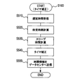
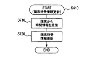
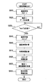
- FIG. 9 is a flowchart showing timer value correction processing in standby processing according to the second embodiment of the present disclosure. It is a flowchart figure which shows the delay information transmission process of the calling process along 2nd embodiment of this indication, It is a flowchart figure which shows the terminal device stand-by information update process of the call processing along the second embodiment of the present disclosure, FIG. 7 is a flowchart illustrating a timer value correction process according to another embodiment of the present disclosure; It is a flowchart figure which shows the delay information generation process of the calling process along other embodiment of this indication.
- the communication system 1 is configured such that the wireless terminal device 10 mounted on a vehicle and the data center 60 exchange data.
- the wireless terminal device 10 transmits data from the data center 60. It is devised to save more power in the standby state until reception.
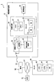
- the communication system 1 includes a wireless terminal device 10 mounted on a vehicle, a base station 50, an NTP (Network Time Protocol) server 52, and a data center 60, as shown in FIG.
- a large number of base stations 50 and wireless terminal devices 10 are arranged, and the data center 60 exchanges data with a large number of wireless terminal devices 10.
- the base station 50 is configured as a wireless base station of a mobile phone, for example, and performs wireless communication with one or a plurality of wireless terminal devices 10 existing within a communicable range and is connected to various types connected via the Internet network 51. It communicates with devices (such as the NTP server 52 and the data center 60).
- the NTP server 52 is a server for synchronizing the clock of each device with the correct time, and the wireless terminal device 10 and the data center 60 obtain the correct time by accessing the server 52.
- the wireless terminal device 10 or the data center 60 may synchronize the time of its own clock with the correct time based on time information received by a receiver such as a GPS (Global Positioning System).
- “information” is used not only as a countable noun but also as a countable noun. That is, a plurality of information is recognized as being equivalent to, for example, a plurality of pieces of information or a plurality of information items.
- the wireless terminal device 10 includes a control circuit 20, a communication module 30, and an abnormality detection unit 35.
- the control circuit 20 can also be referred to as a control calculation unit.
- the control circuit 20 is configured as a computer including a CPU 21 and a memory 22 such as a ROM and a RAM.
- a clock generator 23 having two types of clocks, a high-speed clock 24 and a low-speed clock 25, is provided.
- the CPU 21 executes various processes such as a standby process to be described later based on a program stored in the memory 22. At this time, processing is performed according to a low-speed or high-speed clock generated by the clock generation unit 23.
- the wireless terminal device 10 operates according to LTE (Long Term Evolution), which is one of communication standards for mobile phones, and performs intermittent standby when receiving an incoming call.
- Intermittent standby refers to a state in which a signal related to an incoming call from the base station 50 can be received (a state in which a call can be received) and a state in which the signal is not received (a state in which a call cannot be received).
- Etc. shows the standby operation repeated.
- the base station 50 is set to establish a connection by causing the wireless terminal device to receive a call when the wireless terminal device 10 is ready to receive a signal related to the incoming call from the base station 50.
- the high-speed clock 24 in the clock generation unit 23 generates a clock when a call can be received or when communication with the base station 50 is performed.
- the low speed clock 25 always generates a clock. In this configuration, only the low-speed clock 25 operates when the call cannot be received, and power saving is achieved by stopping the high-speed clock 24 that generally consumes a large amount of power.
- the wireless terminal device 10 periodically performs an intermittent standby state in which the incoming call ready state and the incoming call impossible state are switched in a relatively short time and a sleep state in which the incoming call impossible state is continued for a relatively long time. It is set to repeat (see FIGS. 4A and 4B, details will be described later).
- This cycle is shared with the data center 60 as a reference cycle.
- the reference period can be acquired from the data center 60 at the time of initial communication with the data center 60 together with an incoming call start time and an incoming call end time, which will be described later.
- the communication module 30 is also referred to as a communication control circuit.
- the communication module 20 has a function as a well-known communication module that makes a call or a call by a command from the control circuit 20 or a signal from the base station 50.
- the communication module 30 includes a transmission / reception unit 31 and an intermittent reception control unit 32.
- the transmission / reception unit 31 has a function of converting data that has been instructed to be transmitted from the control circuit 20 into a packet of a predetermined format and transmitting it, a function of restoring a packet received from the base station 50 into data, and the like. . In addition, the transmission / reception unit 31 switches between an incoming call ready state and an incoming call impossible state according to a command from the intermittent reception control unit 32.
- the abnormality detection unit 35 is configured as a general device that detects an abnormality occurring in the vehicle such as theft or failure of the vehicle, and sends it to the control circuit 20 when an abnormality is detected.
- the control circuit 20 is configured to call the data center 60 that an abnormality has occurred when an abnormality occurs.
- description is abbreviate
- the data center 60 is configured as a computer including a CPU 61 and a memory 62 such as a ROM and a RAM.
- the data center 60 includes a shared information database 63.
- the shared information database 63 the incoming call start time when each wireless terminal apparatus 10 enters the intermittent standby state and the incoming call end time when the wireless terminal apparatus 10 enters the sleep state are recorded.
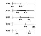
- the incoming call start time and incoming call end time for each wireless terminal device 10 are set to be as different as possible for each wireless terminal device 10 as shown in FIG. In other words, since the time points of calling by the data center 60 are set to be distributed for each wireless terminal device 10, it is possible to suppress the concentration of processing when the data center 60 makes calls.
- the call point for each wireless terminal device 10 by the data center 60 is set to coincide with the call start time. Note that, at the time of call origination, since the signal due to the call should arrive at the wireless terminal device 10 between the call start time and the call end time (see FIG. 4B), the delay time of the signal due to the call is taken into consideration. Then, it may be set at a time before or after the incoming call start time.
- each section is expressed as S110, for example.
- each section can be divided into a plurality of subsections, while a plurality of sections can be combined into one section.
- each section configured in this manner can be referred to as a device, module, or means.
- each of the above sections or a combination thereof includes not only (i) a section of software combined with a hardware unit (eg, a computer), but also (ii) hardware (eg, an integrated circuit, As a section of (wiring logic circuit), it can be realized with or without the function of related devices.
- the hardware section can be configured inside the microcomputer.
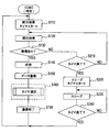
- the standby processing by the wireless terminal device 10 is started when the power of the wireless terminal device 10 is turned on by the control circuit 20, specifically, the CPU 21, and is repeated when a call is not made from itself. To be implemented.
- a timer in the intermittent standby mode indicating the duration of the intermittent standby state is started (S110), and intermittent standby is performed.
- the receiving state is set (S120).
- the intermittent standby state as shown in FIG. 4A, the incoming call ready state and the incoming call impossible state are switched in a relatively short time (for example, a cycle of 1.28 seconds).
- S130 it is determined whether there is an incoming call (S130). If there is an incoming call (S130: YES), a known process for responding to the incoming call is performed (S140), and data communication is executed (S150). When the data transmission / reception is completed, a known process for terminating the communication is performed (S190), and the process returns to S110.
- the timer in the intermittent standby mode is set to a value of about 10 seconds, for example.
- the process returns to S120. If the timer has expired (S210: NO), the process returns to S120. If the timer has expired (S210: YES), the sleep mode timer indicating the duration of the sleep state is started (S220), and the wireless terminal device 10 is set to the sleep state (S230). In the sleep state, power is saved by stopping the communication module 30 and stopping functions other than the function of managing the timer (low-speed clock) and the function of detecting vehicle abnormality. In the sleep state, the incoming call is not accepted. However, during this time, the data center 60 does not make a call, so that the incoming call cannot be accepted (see FIG. 4A).
- S240 it is determined whether or not the sleep mode timer has expired. If the timer has not expired (S240: NO), the process returns to S230. If the timer has expired (S240: YES), the process returns to S110.
- the calling process is a process performed when information or a command is transmitted from the data center 60 to a corresponding vehicle in response to a request from a vehicle user or a vehicle manufacturer.
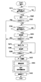
- the target wireless terminal device 10 is in an intermittent standby state (S310). Since the data center 60 has a reference cycle synchronized with each wireless terminal device 10, the data center 60 recognizes whether each wireless terminal device 10 is in an intermittent standby state or a sleep state.
- the process of S310 is repeated. If the target wireless terminal device 10 is in the intermittent standby state (S310: YES), a call is made to the target wireless terminal device 10 (S320).
- the presence / absence of a response from the wireless terminal device 10 is determined (S360). If there is a response (S360: YES), the process proceeds to S400 described later. If there is no response (S360: NO), the calling time is shifted (S370).
- the shift of the call origination time means changing the time of the call origination in the reference period. For example, in the case where the reference period is 30 seconds, if it is set to make a call at the time of 0 seconds after the start of the reference period, the time point of the call is delayed by about 10 seconds, for example. Change to place a call at 10 seconds.
- the presence / absence of a response from the wireless terminal device 10 is determined (S360). If there is no response (S360: NO), the process returns to S370. If there is a response (S360: YES), data communication is executed (S400), and when the data transmission / reception is completed, a known process for terminating the communication is performed (S460), and the calling process is terminated.
- the control circuit 20 of the wireless terminal device 10 has the data center 60 connected to the wireless terminal within the reference period shared with the data center 60 that is the communication partner of the wireless terminal device 10.
- the wireless terminal device 10 is set to an intermittent standby state.
- the wireless terminal device 10 is set to a sleep state in which no incoming call is accepted.
- the incoming call ready time is also referred to as an incoming call intermittent standby time.
- the data center 60 transmits some information (such as a digital signal including a packet or other data) to the wireless terminal device 10.
- the data center 60 is within the reference period shared with the wireless terminal device 10. The call is made when the call time set in advance as the time when the call is made to 10 is reached.
- the wireless terminal device 10 shares a reference period with the data center 60, and is a time during which an incoming call can be substantially received in a period in which there is a possibility of receiving an incoming call in relation to a call origination point within the reference period (That is, an intermittent standby state is set as an incoming call ready time).
- an intermittent standby state is set as an incoming call ready time.
- the intermittent standby state is shifted to the sleep state.
- the high-speed clock 24, which generally consumes a large amount of power, is stopped by shifting to the sleep state during a time when no incoming call is received in relation to the time of call. Electricity is being planned.
- the time point of entering the sleep state is set in consideration of the delay.
- the wireless terminal device 10 is used by being mounted on a vehicle.
- the wireless terminal device 10 mounted on the vehicle causes the battery of the vehicle to increase when the power consumption increases while the vehicle is parked, that is, in a state where the engine is stopped and the vehicle battery is not charged from the alternator. For this reason, when the radio
- the wireless terminal device 10 when the wireless terminal device 10 receives an incoming call from the data center 60 in the intermittent standby state, the wireless terminal device 10 prohibits the transition to the sleep state.
- the wireless terminal device 10 when receiving an incoming call from the data center 60 in the intermittent standby state, the wireless terminal device 10 prohibits the transition to the sleep state until the processing associated with the incoming call is completed.
- the data center 60 determines whether or not there is a response from the wireless terminal device 10 to the call from itself, and if there is no response from the wireless terminal device 10 to this call, When the call is made, another call is made.
- the data center 60 determines whether or not there is a response from the wireless terminal device 10 to the call from itself, and if there is no response from the wireless terminal device 10 to this call, A call is made again when a predetermined time set in advance or subtracted from the call time.
- the call origination time is set for a predetermined time. Since it is possible to make another call by shifting, it can be expected that a response is obtained by this call. Therefore, the reliability of communication can be improved.
- a plurality of wireless terminal devices 10 are provided, and the data center 60 is set such that the initial calling section is distributed with respect to the calling time points for the wireless terminal devices 10.
- a timer value correction process is performed between the processes of S150 and S190 (S160).
- delay information delay time information transmitted from the data center 60 is received (S510).
- the sleep possible time is calculated (S530).
- the reference cycle that is the sum of the time in the intermittent standby state and the time in the sleep state is determined, it can be obtained by subtracting the time in the intermittent standby state from the reference cycle.
- the intermittent standby timer and the sleep timer are corrected according to the time of each state obtained in S520 to S530 (S540), and the time of each state is transmitted to the data center 60 (S550).
- the timer value correction processing ends.
- timer value correction processing in the data center 60 of the second embodiment, in the call processing shown in FIG. 5, the delay information transmission processing and the terminal device standby information between the processing of S400 and S460. Update processing is performed (S410).
- a timer for measuring the delay time is started (S610). Subsequently, data is transmitted to the wireless terminal device 10 (S620), and it is determined whether or not “Ack” corresponding to the response of this data has been received from the wireless terminal device 10 (S630).
- the process returns to S630. If “Ack” has not been received (S630: NO), the process returns to S630. If “Ack” is received (S630: YES), the timer for measuring the delay time is stopped (S640), and the time when the timer is stopped is calculated as the delay time (S650). Then, the delay time is transmitted as delay information to the wireless terminal device 10 (S660), and the delay information transmission process is terminated.
- the time of the intermittent standby state and the time of the sleep state are received from the wireless terminal device 10 (S710).
- the time start time and end time of the intermittent standby state with respect to the reference period
- the shared information database 63 S720.
- the wireless terminal device 10 acquires delay information related to the network delay time when communicating with the data center 60, and based on the delay information, the incoming call start time and the incoming call are obtained. Set at least one of the end points.
- Embodiments of the present disclosure are not limited to the above-described embodiments, and may take various forms as long as they belong to the technical scope of the present disclosure.
- the wireless terminal device 10 may calculate the delay time in the second embodiment, the data center 60 may calculate the delay time. In this case, the wireless terminal device 10 may perform a timer value correction process as shown in FIG. 7B.
- delay information (intermittent standby state time and sleep state time) generated in the data center 60 is received (S760). Based on this, the intermittent standby state time and sleep state time may be set (S770).
- the delay information generation process shown in FIG. 8 may be performed as a process corresponding to the modified timer value correction process.
- the delay information generation process may be performed in place of the delay information transmission process and the terminal device standby information update process shown in the second embodiment.
- the same process as the process of S610 to S650 described above is performed. Subsequently, based on the delay information, the time required for the intermittent standby state is calculated (S810). In this process, the same process as in S520 described above can be performed.
- the sleep possible time is calculated (S820).
- the sleep possible time is obtained by subtracting the time in the intermittent standby state from the reference period.
- the delay information is transmitted to the wireless terminal device 10 using the time of the intermittent standby state and the time of the sleep state as delay information (S830), and the standby time of the wireless terminal device 10 (intermittent standby state with respect to the reference period) Is updated in the shared information database 63 (S840).
- the delay information generation processing ends.
- wireless terminal apparatus 10 is not restricted to a vehicle, For example, by the monitoring apparatus and user who monitor a plant etc. You may apply as a portable terminal device etc. which are carried.
- the wireless terminal device 10 of the embodiment is also referred to as a wireless communication device.
- the data center 60 of the above embodiment is also referred to as a communication target device.
- the processes of S110 to S130 and S210 are also referred to as an intermittent standby setting section.
- the processing of S130 to S190 is also referred to as a sleep transition prohibition section.
- the processes of S220 to S240 among the processes of the above embodiment are also referred to as a sleep state setting section.
- the processes of 310 and S320 are also referred to as an initial call section.
- the process of S330 among the processes of the said embodiment is also referred to as a first response determination section.
- the processes of S340 and S350 are also referred to as a first recalling section.
- the process of S360 among the processes of the above embodiment is also referred to as a second response determination section.
- the processes of S370 and S380 are also referred to as a second re-call section.
- the processes of S510 and S760 are also referred to as a delay acquisition section.
- the process of S540 is also referred to as an incoming call time setting section.
Landscapes
- Engineering & Computer Science (AREA)
- Computer Networks & Wireless Communication (AREA)
- Signal Processing (AREA)
- Mobile Radio Communication Systems (AREA)
- Telephone Function (AREA)
Abstract
通信システム(1)において無線端末装置(10)は、データセンタ(60)と基準周期を共有する。この基準周期内に、データセンタが発呼する発呼時点と対応する着呼開始時点から、この発呼の遅延を加味して設定される着呼終了時点までを着呼レディ時間とし、この着呼レディ時間において、無線端末装置を間欠待受状態に設定する(S110~S130、S210)。そして、基準周期内のうちの着呼レディ時間を除く時間において、当該無線端末装置を、着呼を受け付けないスリープ状態に設定する(S220~S240)。
Description
本開示は、2013年2月20日に出願された日本出願番号2013-31265号に基づくもので、ここにその記載内容を援用する。
本開示は、間欠的に着呼を受け付ける間欠待受状態にて待ち受けを行う機能を有する無線通信装置、および通信システムに関する。
待ち受けの際の消費電力を節約するために、着呼可能な状態と、一定時間だけ着呼不能にすることで節電する状態とを交互に繰り返すことで間欠的に着呼を受け付ける間欠待受状態にて待ち受けを行う機能を有する無線通信装置が知られている(例えば、特許文献1参照)。
例えば、近年普及しつつあるLTE(Long Term Evolution)等、通信態様によっては間欠待受状態において節電できる時間が短くなり、無線通信装置の待受電力使用量が多くなる。そこで、無線通信装置の待受電力使用量を低減できるようにすることを本開示の目的とする。
かかる目的を達成するために成された本開示の第一の例によれば、無線通信装置は、間欠的に着呼を受け付ける間欠待受状態にて待ち受けを行う機能を有するように提供される。当該無線通信装置は、通信相手となる通信対象装置と基準周期を共有する。当該無線通信装置は、間欠待受設定セクションとスリープ状態設定セクションを含む。間欠待受設定セクションは、前記通信対象装置と共有されている基準周期内において、前記通信対象装置が発呼する発呼時点と対応する着呼開始時点から、前記発呼の遅延を加味して設定される着呼終了時点までを着呼レディ時間とし、この着呼レディ時間において、当該無線通信装置を前記間欠待受状態に設定する。そして、スリープ状態設定セクションは、前記基準周期内のうちの前記着呼レディ時間を除く時間において、当該無線通信装置を、着呼を受け付けないスリープ状態に設定する。
すなわち、上記構成の無線通信装置では、通信対象装置と基準周期を共有し、基準周期内において発呼時点との関係で着呼を受ける可能性がある時間においては着呼レディ時間として間欠待受状態に設定する。一方で、発呼時点との関係で着呼を受けない時間においては間欠待受状態からスリープ状態に移行する。
したがって、このような無線通信装置によれば、発呼時点との関係で着呼を受けない時間においてスリープ状態に移行することによって、通信対象装置からの着呼を逃すことがないようにしつつ、待ち受けを行う際の消費電力を抑制することができる。
なお、着呼開始時点は、発呼時点そのものや発呼時点から遅延を考慮した所定時間後に設定されていればよい。また、このような無線通信装置は、車両に搭載して利用することも考えられる。
車両に搭載された無線通信装置は、駐車中など、すなわちエンジンが停止していてオルタネータから車両バッテリに充電されない状態での消費電力が大きくなると車両のバッテリ上がりの原因となる。このため、上記の無線通信装置を車載用の無線通信装置として採用すると、バッテリ上がりを抑制することができ好ましい。
なお、上記目的を達成するためには、コンピュータを、無線通信装置または通信対象装置を構成する要素として実現するためのプログラム製品としてもよい。
また、各請求項の記載は、可能な限りにおいて任意に組み合わせることができる。この際、本開示の目的を達成できる範囲内において一部構成を除外してもよい。
本開示についての上記目的およびその他の目的、特徴や利点は、添付の図面を参照しながら下記の詳細な記述により、より明確になる。
本開示の第一実施形態に沿った通信システムの概略構成を示すブロック図であり、
データセンタの発呼時点を示す説明図であり、
制御回路が実行する待受処理を示すフローチャート図であり、
間欠待受状態とスリープ状態とを示すタイムチャート図であり、
間欠待受状態とスリープ状態とを示すタイムチャート図であり、
データセンタが実行する発呼処理を示すフローチャート図であり、
本開示の第二実施形態に沿った、待受処理のうちのタイマ値補正処理を示すフローチャート図であり、
本開示の第二実施形態に沿った、発呼処理のうちの遅延情報送信処理を示すフローチャート図であり、
本開示の第二実施形態に沿った、発呼処理のうちの端末装置待受情報更新処理を示すフローチャート図であり、
本開示のその他の実施形態に沿った、タイマ値補正処理を示すフローチャート図であり、
本開示のその他の実施形態に沿った、発呼処理のうちの遅延情報生成処理を示すフローチャート図である。
以下に本開示にかかる実施の形態を図面と共に説明する。
[第1実施形態]
[本実施形態の構成]
本実施形態の通信システム1は、車両に搭載された無線端末装置10と、データセンタ60とがデータのやり取りを行うよう構成されており、特に、無線端末装置10がデータセンタ60からのデータを受信するまでの待受状態において、より節電できるよう工夫されている。
[本実施形態の構成]
本実施形態の通信システム1は、車両に搭載された無線端末装置10と、データセンタ60とがデータのやり取りを行うよう構成されており、特に、無線端末装置10がデータセンタ60からのデータを受信するまでの待受状態において、より節電できるよう工夫されている。
すなわち通信システム1は、図1に示すように、車両に搭載された無線端末装置10と、基地局50と、NTP(Network Time Protocol)サーバ52と、データセンタ60と、を備えている。なお、基地局50や無線端末装置10は、多数配置されており、データセンタ60は多数の無線端末装置10とのデータのやり取りを行う。
基地局50は、例えば携帯電話の無線基地局として構成されており、通信可能範囲内に存在する1または複数の無線端末装置10と無線通信を行うとともに、インターネット網51を介して接続された各種装置(NTPサーバ52やデータセンタ60等)との通信を行う。
NTPサーバ52は、各装置が持つ時計を正しい時刻に同期させるためのサーバであり、無線端末装置10やデータセンタ60は、このサーバ52にアクセスすることで正しい時刻を取得する。なお、無線端末装置10やデータセンタ60は、GPS(全地球測位システム)等の受信機で受信される時刻情報によって自身が持つ時計の時刻を正しい時刻に同期させてもよい。
尚、本願では、「情報」は不可算名詞のみならず可算名詞としても使用される。すなわち、複数の情報は、たとえば、複数の情報のピーシーズあるいは複数の情報項目と同等として認識される。
無線端末装置10は、制御回路20と、通信モジュール30と、異常検出部35とを備えている。制御回路20は、制御演算部とも言及できる。制御回路20は、CPU21、およびROM、RAM等のメモリ22を備えたコンピュータとして構成されている。そして、高速クロック24と低速クロック25との2種類のクロックを備えたクロック生成部23を備えている。
CPU21は、メモリ22に格納されたプログラムに基づいて、後述する待受処理等の各種処理を実行する。この際、クロック生成部23にて生成される低速または高速のクロックに従って処理を行う。
ここで、無線端末装置10は、携帯電話機における通信規格の1つであるLTE(Long Term Evolution)に従って作動し、外部からの着呼を受け付ける際に間欠待受を行う。なお、間欠待受とは、基地局50からの着呼に関する信号を受けられる状態(着呼可能状態)と、そうでない状態(着呼不能状態)とを比較的短い周期(例えば1.28秒等)で繰り返す待受動作を示す。
基地局50は、無線端末装置10が基地局50からの着呼に関する信号を受けられる状態のときに無線端末装置へ着呼させることにより、接続が確立するよう設定されている。
クロック生成部23のうちの高速クロック24は、着呼可能状態のときや基地局50との通信を行っているときにクロックを生成する。また、低速クロック25は、常時クロックを生成する。この構成では、着呼不能状態のときには低速クロック25だけが作動し、一般的に消費電力が大きい高速クロック24を停止させることで省電力化を図っている。
特に、無線端末装置10は、着呼可能状態と着呼不能状態とを比較的短時間で切り替える間欠待受状態と、比較的長時間、着呼不能状態を継続するスリープ状態とを周期的に繰り返すよう設定されている(図4A,図4Bを参照、詳細は後述する)。なお、この周期については、基準周期としてデータセンタ60と共有されている。例えば、基準周期は、後述する着呼開始時刻および着呼終了時刻とともに、データセンタ60との初回通信時にデータセンタ60から取得することができるよう構成されている。
次に、通信モジュール30は、通信制御回路とも言及される。通信モジュール20は、制御回路20からの指令や基地局50からの信号によって発呼または着呼を行う周知の通信モジュールとしての機能を備えている。また、通信モジュール30は、送受信部31と、間欠受信制御部32とを備えている。
送受信部31は、制御回路20から送信するよう指示を受けたデータを所定の形式のパケットに変換して送信する機能や、基地局50から受信したパケットをデータに復元する機能等を備えている。また、送受信部31は、間欠受信制御部32からの指令に応じて着呼可能状態と着呼不能状態とを切り替える。
異常検出部35は、車両の盗難や故障等の車両に発生する異常を検出する一般的な装置として構成されており、異常を検出すると制御回路20に送る。制御回路20では、異常が発生するとデータセンタ60に対して異常が発生した旨を発呼するよう構成されている。なお、無線端末装置10側から発呼を行う処理については、周知の処理を採用することができるため、本明細書では説明を省略する。
データセンタ60は、CPU61、およびROM、RAM等のメモリ62を備えたコンピュータとして構成されている。そして、データセンタ60は、共有情報データベース63を備えている。共有情報データベース63には、各無線端末装置10が、前述の基準周期のうちの間欠待受状態になる着呼開始時刻およびスリープ状態になる着呼終了時刻が記録されている。
なお、各無線端末装置10についての着呼開始時刻および着呼終了時刻は、図2に示すように、無線端末装置10毎に、極力異なる時刻になるよう設定されている。つまり、データセンタ60による発呼時点が無線端末装置10毎に分散するよう設定されていることで、データセンタ60が発呼する際の処理が集中することを抑制している。
データセンタ60による各無線端末装置10に対する発呼時点は、着呼開始時刻と一致するよう設定されている。なお、発呼時点は、発呼による信号が着呼開始時刻から着呼終了時刻までの間に無線端末装置10に到達すればよいため(図4B参照)、発呼による信号の遅延時間を考慮して着呼開始時刻前後の時点に設定されていてもよい。
[本実施形態の処理]
このような通信システム1において実施される処理について以下に説明する。
このような通信システム1において実施される処理について以下に説明する。
ここで、この出願に記載されるフローチャート、あるいは、フローチャートの処理は、複数のセクション(あるいはステップと言及される)から構成され、各セクションは、たとえば、S110と表現される。さらに、各セクションは、複数のサブセクションに分割されることができる、一方、複数のセクションが合わさって一つのセクションにすることも可能である。さらに、このように構成される各セクションは、デバイス、モジュール、ミーンズとして言及されることができる。また、上記の複数のセクションの各々あるいは組合わさったものは、(i)ハードウエアユニット(例えば、コンピュータ)と組み合わさったソフトウエアのセクションのみならず、(ii)ハードウエア(例えば、集積回路、配線論理回路)のセクションとして、関連する装置の機能を含みあるいは含まずに実現できる。さらに、ハードウエアのセクションは、マイクロコンピュータの内部に構成されることもできる。
まず、無線端末装置10による待受処理は、制御回路20、具体的には、CPU21により、無線端末装置10の電源が投入されると開始され、自身から発呼を実施していない場合に繰り返し実施される。
詳細には、制御回路20が実行する図3のフローチャートに示すように、待受処理では、まず、間欠待受状態の継続時間を表す間欠待受モードのタイマを開始し(S110)、間欠待受状態とする(S120)。間欠待受状態では、図4Aに示すように、着呼可能状態と着呼不能状態とを比較的短時間(例えば、1.28秒周期)で切り替える。
続いて、着呼があったか否かを判定する(S130)。着呼があれば(S130:YES)、着呼に応答する周知の処理を行い(S140)、データ通信を実行する(S150)。そして、データの送受信が終了すると通信を終了する周知の処理を行い(S190)、S110の処理に戻る。
S130の処理において着呼がなければ(S130:NO)、間欠待受モードのタイマが満了したか否かを判定する(S210)。ここで、間欠待受モードのタイマは例えば10秒程度の値に設定される。
タイマが満了していなければ(S210:NO)、S120の処理に戻る。また、タイマが満了していれば(S210:YES)、スリープ状態の継続時間を表すスリープモードのタイマをスタートさせ(S220)、無線端末装置10をスリープ状態とする(S230)。スリープ状態においては、通信モジュール30を停止させるとともに、タイマ(低速クロック)を管理する機能や車両の異常を検出する機能以外の機能を停止させることによって節電を行う。なお、スリープ状態においては、着呼を受け付けない状態とされるが、この間、データセンタ60は発呼しないため着呼が受けられないということはない(図4A参照)。
続いて、スリープモードのタイマが満了したか否かを判定する(S240)。タイマが満了していなければ(S240:NO)、S230の処理に戻る。また、タイマが満了していれば(S240:YES)、S110の処理に戻る。
このような着呼処理に対応して、データセンタ60では図5に示す発呼処理をCPU61が行う。発呼処理は、車両ユーザや車両メーカからの要求等により、データセンタ60から該当車両へ情報や命令を送信する場合に実施される処理である。
発呼処理では、図5に示すように、対象となる無線端末装置10が間欠待受状態であるか否かを判定する(S310)。なお、データセンタ60は各無線端末装置10と同期した基準周期を持っているため、各無線端末装置10が間欠待受状態かスリープ状態かを認識している。
対象となる無線端末装置10が間欠待受状態でなければ(S310:NO)、S310の処理を繰り返す。また、対象となる無線端末装置10が間欠待受状態であれば(S310:YES)、対象となる無線端末装置10への発呼を行う(S320)。
続いて、無線端末装置10からの応答の有無を判定する(S330)。応答があれば(S330:YES)、後述するS400の処理に移行する。また、応答がなければ(S330:NO)、対象となる無線端末装置10が間欠待受状態(S320の発呼を行った間欠待受状態の後のスリープ状態を経てからの間欠待受状態)であるか否かを判定する(S340)。
間欠待受状態でなければ(S340:NO)、S340の処理を繰り返す。また、間欠待受状態であれば(S340:YES)、対象となる無線端末装置10への再度の発呼を行う(S350)。
続いて、無線端末装置10からの応答の有無を判定する(S360)。応答があれば(S360:YES)、後述するS400の処理に移行する。また、応答がなければ(S360:NO)、発呼時点のシフトを行う(S370)。
ここで、発呼時点のシフトとは、基準周期において発呼を行う時点を変更することを示す。例えば、基準周期が30秒である場合において、基準周期開始後0秒の時点で発呼を行うよう設定されていた場合には、例えば10秒程度、発呼の時点を遅らせ、基準周期開始後10秒の時点で発呼を行うよう変更する。
続いて、シフトを行った時点において、対象となる無線端末装置10への再度の発呼を行う(S380)。
続いて、無線端末装置10からの応答の有無を判定する(S360)。応答がなければ(S360:NO)、S370の処理に戻る。また、応答があれば(S360:YES)、データの通信を実行し(S400)、データの送受信が終了すると通信を終了する周知の処理を行い(S460)、発呼処理を終了する。
[本実施形態による効果]
以上のように詳述した通信システム1において、無線端末装置10の制御回路20は、無線端末装置10の通信相手となるデータセンタ60と共有されている基準周期内において、データセンタ60が無線端末装置10に発呼する発呼時点と対応する着呼開始時点から、無線端末装置10における着呼の遅延を加味して設定される着呼終了時点までの実質的に着呼が可能な時間である着呼レディ時間において、無線端末装置10を間欠待受状態に設定する。そして、基準周期内のうちの着呼レディ時間(すなわち、間欠待受状態の時間)を除く時間において、当該無線端末装置10を、着呼を受け付けないスリープ状態に設定する。尚、着呼レディ時間は、着呼間欠待受時間とも言及される。
以上のように詳述した通信システム1において、無線端末装置10の制御回路20は、無線端末装置10の通信相手となるデータセンタ60と共有されている基準周期内において、データセンタ60が無線端末装置10に発呼する発呼時点と対応する着呼開始時点から、無線端末装置10における着呼の遅延を加味して設定される着呼終了時点までの実質的に着呼が可能な時間である着呼レディ時間において、無線端末装置10を間欠待受状態に設定する。そして、基準周期内のうちの着呼レディ時間(すなわち、間欠待受状態の時間)を除く時間において、当該無線端末装置10を、着呼を受け付けないスリープ状態に設定する。尚、着呼レディ時間は、着呼間欠待受時間とも言及される。
また、データセンタ60は、無線端末装置10に対して何らかの情報(パケットその他のデータが含まれるデジタル信号等)を送信する際に、無線端末装置10と共有されている基準周期内において無線端末装置10に発呼する時点として予め設定された発呼時点になると発呼を行う。
すなわち、無線端末装置10は、データセンタ60と基準周期を共有し、基準周期内において発呼時点との関係で着呼を受ける可能性がある時間においては実質的に着呼が可能な時間(すなわち、着呼レディ時間)として間欠待受状態に設定する。一方で、発呼時点との関係で着呼を受けない時間(着呼アンレディ時間とも言及)においては間欠待受状態からスリープ状態に移行する。
したがって、このような無線端末装置10によれば、発呼時点との関係で着呼を受けない時間においてスリープ状態に移行することによって、一般的に消費電力が大きい高速クロック24を停止させ、省電力化を図っている。ただし、図4Bに示すように、データセンタ60による発呼は遅延が生じるため、遅延を考慮してスリープ状態に移行する時点を設定している。
よって、データセンタ60からの着呼を逃すことがないようにしつつ、待ち受けを行う際の消費電力を抑制することができる。
また、無線端末装置10は、車両に搭載して利用される。車両に搭載された無線端末装置10は、駐車中など、すなわちエンジンが停止していてオルタネータから車両バッテリに充電されない状態での、消費電力が大きくなると車両のバッテリ上がりの原因となる。このため、無線端末装置10を車載用の無線端末装置として採用すると、バッテリ上がりを抑制することができ好ましい。
また、上記通信システム1において無線端末装置10は、間欠待受状態においてデータセンタ60からの着呼を受けると、スリープ状態に移行することを禁止する。
このような通信システム1によれば、着呼を受け、着呼に伴う処理が実施されているときにスリープ状態に移行することを抑制することができる。
さらに、上記通信システム1において無線端末装置10は、間欠待受状態においてデータセンタ60からの着呼を受けると、当該着呼に伴う処理が終了するまで、スリープ状態に移行することを禁止する。
このような通信システム1によれば、着呼に伴う処理が終了するまで、スリープ状態に移行することを禁止するので、着呼に伴う処理が終了すると、スリープ状態に移行することができるようになる。よって、着呼に伴う処理を確実に実施しつつ、待ち受けを行う際の消費電力を抑制することができる。
また、上記通信システム1においてデータセンタ60は、自身からの発呼に対する無線端末装置10からの応答の有無を判定し、この発呼に対して無線端末装置10からの応答がない場合、次の発呼時点で再度の発呼を行う。
このような通信システム1によれば、データセンタ60において無線端末装置10からの応答が得られない場合、次の発呼時点で再度の発呼を行うので、再度の発呼によって応答が得られることを期待できる。よって通信の確実性を向上させることができる。
さらに、上記通信システム1においてデータセンタ60は、自身からの発呼に対する無線端末装置10からの応答の有無を判定し、この発呼に対して無線端末装置10からの応答がない場合、次の発呼時点に対して予め設定された所定時間だけ加算または減算した時点で再度の発呼を行う。
このような通信システム1によれば、基準周期や発呼(着呼)時点の同期がとれていない(基準周期の開始時点がずれている)場合であっても、所定時間だけ発呼時点をずらして再度の発呼を行うことができるので、この発呼によって応答が得られることを期待できる。よって、通信の確実性を向上させることができる。
また、上記通信システム1において無線端末装置10は複数備えられており、データセンタ60は、初期発呼セクションが各無線端末装置10に対する発呼時点が分散するよう設定されている。
このような通信システム1によれば、各無線端末装置10に対する発呼時点を分散することができるので、データセンタ60の処理負荷がある時間だけに集中することを抑制することができる。
[第2実施形態]
次に、別形態の通信システムについて説明する。本実施形態(第2実施形態)では、第1実施形態の通信システム1と異なる箇所のみを詳述し、第1実施形態の通信システム1と同様の箇所については、同一の符号を付して説明を省略する。
次に、別形態の通信システムについて説明する。本実施形態(第2実施形態)では、第1実施形態の通信システム1と異なる箇所のみを詳述し、第1実施形態の通信システム1と同様の箇所については、同一の符号を付して説明を省略する。
第2実施形態の無線端末装置10では、図3に示す待受処理において、S150とS190との処理の間でタイマ値補正処理を実施する(S160)。タイマ値補正処理では、図6Aに示すように、まず、データセンタ60から送信された遅延情報(遅延時間の情報)を受信する(S510)。
そして、遅延情報に基づいて、間欠待受状態に必要な時間を計算する(S520)。例えば、端末の断続受信周期:1.28秒、データセンタ発呼から端末応答までの時間:0.5秒、センターと端末の時刻同期ずれ:1秒、ネットワーク混雑時の遅延時間:2秒、マージン:1秒とした場合、1.28+0.5+1+2+0.7=5.78秒と求めることができる。
続いて、スリープ可能時間を計算する(S530)。この処理では、間欠待受状態の時間とスリープ状態の時間の和である基準周期が決まっているので、基準周期から間欠待受状態の時間を差し引くことで求められる。
続いて、間欠待受状態のタイマおよびスリープ状態のタイマをS520~S530で求められた各状態の時間に従って補正し(S540)、各状態の時間をデータセンタ60に対して送信する(S550)。このような処理が終了すると、タイマ値補正処理を終了する。
このようなタイマ値補正処理に対応して、第2実施形態のデータセンタ60では、図5に示す発呼処理において、S400とS460との処理の間で遅延情報送信処理および端末装置待受情報更新処理を実施する(S410)。
遅延情報送信処理では、図6Bに示すように、まず、遅延時間を計測するタイマを開始する(S610)。続いて、無線端末装置10に対してデータを送信し(S620)、このデータの応答に対応する「Ack」を無線端末装置10から受信したか否かを判定する(S630)。
「Ack」を受信していなければ(S630:NO)、S630の処理に戻る。また、「Ack」を受信していれば(S630:YES)、遅延時間を計測するタイマを停止させ(S640)、タイマが停止したときの時間を遅延時間として計算する(S650)。そして、この遅延時間を遅延情報として無線端末装置10に対して送信し(S660)、遅延情報送信処理を終了する。
次に、端末装置待受情報更新処理は、図7Aに示すように、無線端末装置10から間欠待受状態の時間およびスリープ状態の時間を受信し(S710)、この無線端末装置10の待受時点(基準周期に対する間欠待受状態の開始時刻および終了時刻)を共有情報データベース63において更新する(S720)。このような処理が終了すると、端末装置待受情報更新処理を終了する。
このような第2実施形態の通信システムでは、無線端末装置10は、データセンタ60との通信の際のネットワーク遅延時間に関する遅延情報を取得し、遅延情報に基づいて、着呼開始時点および着呼終了時点のうちの少なくとも一方を設定する。
このような通信システムによれば、遅延情報に基づいて発呼から着呼までの遅延時間を推定することができるので、着呼レディ時間をより短くしても着呼を逃しにくくすることができる。よって、より着呼レディ時間を短くすることができるので、待ち受けを行う際の消費電力をより抑制することができる。
[その他の実施形態]
本開示の実施の形態は、上記の実施形態に何ら限定されることはなく、本開示の技術的範囲に属する限り種々の形態を採りうる。
本開示の実施の形態は、上記の実施形態に何ら限定されることはなく、本開示の技術的範囲に属する限り種々の形態を採りうる。
例えば、上記第2実施形態においては、無線端末装置10が遅延時間を計算するよう構成したが、データセンタ60において遅延時間を計算してもよい。この場合、無線端末装置10は、図7Bに示すようなタイマ値補正処理を実施すればよい。
すなわち、変形例のタイマ値補正処理では、図7Bに示すように、データセンタ60において生成された遅延情報(間欠待受状態の時間およびスリープ状態の時間)を受信し(S760)、この情報に基づいて、間欠待受状態の時間およびスリープ状態の時間を設定する(S770)ようにすればよい。
また、データセンタ60においては、変形例のタイマ値補正処理に対応する処理として、図8に示す遅延情報生成処理を実施すればよい。なお、遅延情報生成処理は、第2実施形態に示す遅延情報送信処理および端末装置待受情報更新処理に換えて実施されればよい。
遅延情報生成処理では、図8に示すように、まず、前述のS610~S650の処理と同様の処理を実施する。続いて、遅延情報に基づいて、間欠待受状態に必要な時間を計算する(S810)。この処理では前述のS520と同様の処理とすることができる。
続いて、スリープ可能時間を計算する(S820)。この処理では、S530の処理と同様に、基準周期から間欠待受状態の時間を差し引くことでスリープ可能時間を求める。
そして、間欠待受状態の時間およびスリープ状態の時間を遅延情報として、この遅延情報を無線端末装置10に送信し(S830)、この無線端末装置10の待受時点(基準周期に対する間欠待受状態の開始時刻および終了時刻)を共有情報データベース63において更新する(S840)。このような処理が終了すると、遅延情報生成処理を終了する。
また、上記実施形態においては、本開示を車両に搭載された無線端末装置10に対して適用したが、無線端末装置10は、車両に限らず、例えばプラント等を監視する監視装置や使用者によって所持される携帯端末装置等として適用されてもよい。
また、上記実施形態に示した構成や処理の一部は本開示が成立する範囲内において任意に除外または組み合わせることができる。例えば、S340~S360の処理は、除外されてもよいし、繰り返し適用されてもよい。
[本実施形態の構成]
上記実施形態の無線端末装置10は、無線通信装置とも言及される。上記実施形態のデータセンタ60は、通信対象装置とも言及される。また、上記実施形態の処理のうちS110~S130、S210の処理は、間欠待受設定セクションとも言及される。S130~S190の処理は、スリープ移行禁止セクションとも言及される。
上記実施形態の無線端末装置10は、無線通信装置とも言及される。上記実施形態のデータセンタ60は、通信対象装置とも言及される。また、上記実施形態の処理のうちS110~S130、S210の処理は、間欠待受設定セクションとも言及される。S130~S190の処理は、スリープ移行禁止セクションとも言及される。
さらに、上記実施形態の処理のうちS220~S240の処理は、スリープ状態設定セクションとも言及される。310、S320の処理は、初期発呼セクションとも言及される。また、上記実施形態の処理のうちS330の処理は、第1応答判定セクションとも言及される。S340、S350の処理は、第1再発呼セクションとも言及される。
さらに、上記実施形態の処理のうちS360の処理は、第2応答判定セクションとも言及される。S370、S380の処理は、第2再発呼セクションとも言及される。また、上記実施形態の処理のうちS510、S760の処理は、遅延取得セクションとも言及される。S540の処理は、着呼時間設定セクションとも言及される。
本開示は、実施例に準拠して記述されたが、本開示は当該実施例や構造に限定されるものではないと理解される。本開示は、様々な変形例や均等範囲内の変形をも包含する。加えて、様々な組み合わせや形態、さらには、それらに一要素のみ、それ以上、あるいはそれ以下、を含む他の組み合わせや形態をも、本開示の範疇や思想範囲に入るものである。
Claims (8)
- 間欠的に着呼を受け付ける間欠待受状態にて待ち受けを行う機能を有し、通信相手となる通信対象装置(60)と基準周期を共有する無線通信装置(10)であって、
前記通信対象装置と共有される基準周期内において、前記通信対象装置が発呼する発呼時点と対応する着呼開始時点から、前記発呼の遅延を加味して設定される着呼終了時点までを着呼レディ時間とし、前記着呼レディ時間において、当該無線通信装置を前記間欠待受状態に設定する間欠待受設定セクション(S110~S130、S210)と、
前記基準周期内のうちの前記着呼レディ時間を除く時間において、当該無線通信装置を、着呼を受け付けないスリープ状態に設定するスリープ状態設定セクション(S220~S240)と、
を備えた無線通信装置。 - 請求項1に記載の無線通信装置において、
前記間欠待受状態において前記通信対象装置からの着呼を受けると、前記スリープ状態に移行することを禁止するスリープ移行禁止セクション(S130~S190)、
を備えた無線通信装置。 - 請求項2に記載の無線通信装置において、
前記スリープ移行禁止セクションは、前記間欠待受状態において前記通信対象装置からの着呼を受けると、当該着呼に伴う処理が終了するまで、前記スリープ状態に移行することを禁止する
無線通信装置。 - 請求項1~請求項3の何れか1項に記載の無線通信装置において、
前記通信対象装置との通信の際のネットワーク遅延時間に関する遅延情報を取得する遅延取得セクション(S510、S760)と、
前記遅延情報に基づいて、前記着呼開始時点および前記着呼終了時点のうちの少なくとも一方を設定する着呼時間設定セクション(S540)と、
を備えた無線通信装置。 - 間欠的に着呼を受け付ける間欠待受状態にて待ち受けを行う機能を有する請求項1~請求項4の何れか1項に記載の無線通信装置と、前記無線通信装置の通信相手となる通信対象装置(60)とを備えた通信システム(1)であって、
前記通信対象装置は、前記無線通信装置に対して何らかの情報を送信する際に、前記無線通信装置と共有されている基準周期内において前記無線通信装置に発呼する時点として予め設定された発呼時点になると発呼を行う初期発呼セクション(S310、S320)、
を備えた通信システム。 - 請求項5に記載の通信システムにおいて、
前記通信対象装置は、
自身からの発呼に対する無線通信装置からの応答の有無を判定する第1応答判定セクション(S330)と、
前記第1応答判定セクションによる発呼に対して前記無線通信装置からの応答がない場合、次の発呼時点で再度の発呼を行う第1再発呼セクション(S340、S350)と、
を備えた通信システム。 - 請求項5または請求項6に記載の通信システムにおいて、
前記通信対象装置は、
自身からの発呼に対する無線通信装置からの応答の有無を判定する第2応答判定セクション(S360)と、
前記第2応答判定セクションによる発呼に対して前記無線通信装置からの応答がない場合、次の発呼時点に対して予め設定された所定時間だけ加算または減算した時点で再度の発呼を行う第2再発呼セクション(S370、S380)と、
を備えた通信システム。 - 請求項5~請求項7の何れか1項に記載の通信システムにおいて、
前記無線通信装置は複数備えられており、
前記通信対象装置は、前記初期発呼セクションが各無線通信装置に対する発呼時点が分散するよう設定されている
通信システム。
Priority Applications (1)
| Application Number | Priority Date | Filing Date | Title |
|---|---|---|---|
| US14/768,902 US10142934B2 (en) | 2013-02-20 | 2014-01-27 | Wireless communication apparatus and communication system |
Applications Claiming Priority (2)
| Application Number | Priority Date | Filing Date | Title |
|---|---|---|---|
| JP2013031265A JP6102324B2 (ja) | 2013-02-20 | 2013-02-20 | 通信システム |
| JP2013-031265 | 2013-02-20 |
Publications (1)
| Publication Number | Publication Date |
|---|---|
| WO2014129113A1 true WO2014129113A1 (ja) | 2014-08-28 |
Family
ID=51390921
Family Applications (1)
| Application Number | Title | Priority Date | Filing Date |
|---|---|---|---|
| PCT/JP2014/000384 Ceased WO2014129113A1 (ja) | 2013-02-20 | 2014-01-27 | 無線通信装置、および通信システム |
Country Status (3)
| Country | Link |
|---|---|
| US (1) | US10142934B2 (ja) |
| JP (1) | JP6102324B2 (ja) |
| WO (1) | WO2014129113A1 (ja) |
Cited By (1)
| Publication number | Priority date | Publication date | Assignee | Title |
|---|---|---|---|---|
| JPWO2018134995A1 (ja) * | 2017-01-23 | 2019-06-27 | 三菱電機株式会社 | 基地局、移動局および通信方法 |
Families Citing this family (3)
| Publication number | Priority date | Publication date | Assignee | Title |
|---|---|---|---|---|
| JP6098943B2 (ja) * | 2013-07-31 | 2017-03-22 | パナソニックIpマネジメント株式会社 | コードレス電話システム |
| DE102016212002B4 (de) * | 2016-03-16 | 2018-05-09 | Volkswagen Aktiengesellschaft | Verfahren zum Betreiben einer Mobilfunkstation, sowie Relaisfunkstation und Mobilfunkstation zur Verwendung bei dem Verfahren |
| US11950304B2 (en) | 2018-04-18 | 2024-04-02 | Rochester Institute Of Technology | Direct server-to-server wireless data center network and method thereof |
Citations (5)
| Publication number | Priority date | Publication date | Assignee | Title |
|---|---|---|---|---|
| JPH01147930A (ja) * | 1987-12-03 | 1989-06-09 | Nippon Telegr & Teleph Corp <Ntt> | 無線通信装置 |
| JPH11511923A (ja) * | 1995-05-23 | 1999-10-12 | テレフオンアクチーボラゲツト エル エム エリクソン(パブル) | セルラ通信システム内でスリープ中の移動局へのショート・メッセージサービス・メッセージの配送を支援する方法及び装置 |
| JP2001352570A (ja) * | 2000-06-08 | 2001-12-21 | Nec Corp | 移動局呼び出し方法 |
| JP2010518765A (ja) * | 2007-02-14 | 2010-05-27 | リサーチ イン モーション リミテッド | Lte_activeにおけるdrxタイミング非同期から回復する方法およびシステム |
| JP2012507891A (ja) * | 2008-11-03 | 2012-03-29 | チャイナ アカデミー オブ テレコミュニケーションズ テクノロジー | Ueの省電力性能を強化する方法およびue |
Family Cites Families (11)
| Publication number | Priority date | Publication date | Assignee | Title |
|---|---|---|---|---|
| JP4132266B2 (ja) | 1998-08-19 | 2008-08-13 | 京セラ株式会社 | 移動通信システムにおける制御チャネル検索方法及び携帯通信装置 |
| JP4098942B2 (ja) | 2000-02-10 | 2008-06-11 | 株式会社エヌ・ティ・ティ・ドコモ | 複数方式携帯電話機 |
| JP4225706B2 (ja) | 2001-06-07 | 2009-02-18 | 三洋電機株式会社 | 移動通信端末における間欠受信方法 |
| US20060033744A1 (en) * | 2004-08-13 | 2006-02-16 | Motorola, Inc. | Device and method for continuous screen updates in low-power mode |
| US8073469B2 (en) * | 2005-01-31 | 2011-12-06 | Jasper Wireless, Inc. | Paging for non-real-time communications wireless networks |
| US8072963B2 (en) * | 2007-02-14 | 2011-12-06 | Research In Motion Limited | Method and system for recovering from DRX timing de-synchronization in LTE—ACTIVE |
| CN101483891B (zh) * | 2008-01-08 | 2012-12-05 | 株式会社Ntt都科摩 | 对用户设备设置激活期起始点的方法及装置 |
| JP5391625B2 (ja) | 2008-09-30 | 2014-01-15 | 富士通モバイルコミュニケーションズ株式会社 | 移動無線端末装置 |
| US8462736B2 (en) * | 2009-06-19 | 2013-06-11 | Telefonaktiebolaget L M Ericsson (Publ) | Telecommunications method and apparatus for facilitating positioning measurements |
| JP5672046B2 (ja) * | 2011-02-16 | 2015-02-18 | ソニー株式会社 | 無線通信装置、基地局、無線通信方法、プログラムおよび無線通信システム |
| KR101790036B1 (ko) * | 2011-07-11 | 2017-10-25 | 삼성전자 주식회사 | 이동통신 단말기의 불연속 통신 제어 방법. |
-
2013
- 2013-02-20 JP JP2013031265A patent/JP6102324B2/ja not_active Expired - Fee Related
-
2014
- 2014-01-27 US US14/768,902 patent/US10142934B2/en active Active
- 2014-01-27 WO PCT/JP2014/000384 patent/WO2014129113A1/ja not_active Ceased
Patent Citations (5)
| Publication number | Priority date | Publication date | Assignee | Title |
|---|---|---|---|---|
| JPH01147930A (ja) * | 1987-12-03 | 1989-06-09 | Nippon Telegr & Teleph Corp <Ntt> | 無線通信装置 |
| JPH11511923A (ja) * | 1995-05-23 | 1999-10-12 | テレフオンアクチーボラゲツト エル エム エリクソン(パブル) | セルラ通信システム内でスリープ中の移動局へのショート・メッセージサービス・メッセージの配送を支援する方法及び装置 |
| JP2001352570A (ja) * | 2000-06-08 | 2001-12-21 | Nec Corp | 移動局呼び出し方法 |
| JP2010518765A (ja) * | 2007-02-14 | 2010-05-27 | リサーチ イン モーション リミテッド | Lte_activeにおけるdrxタイミング非同期から回復する方法およびシステム |
| JP2012507891A (ja) * | 2008-11-03 | 2012-03-29 | チャイナ アカデミー オブ テレコミュニケーションズ テクノロジー | Ueの省電力性能を強化する方法およびue |
Cited By (1)
| Publication number | Priority date | Publication date | Assignee | Title |
|---|---|---|---|---|
| JPWO2018134995A1 (ja) * | 2017-01-23 | 2019-06-27 | 三菱電機株式会社 | 基地局、移動局および通信方法 |
Also Published As
| Publication number | Publication date |
|---|---|
| JP6102324B2 (ja) | 2017-03-29 |
| US10142934B2 (en) | 2018-11-27 |
| JP2014160975A (ja) | 2014-09-04 |
| US20160007291A1 (en) | 2016-01-07 |
Similar Documents
| Publication | Publication Date | Title |
|---|---|---|
| US9049658B2 (en) | Power save mechanism for peer-to-peer communication networks | |
| CN109413721B (zh) | 唤醒信号检测时间的配置、检测方法、网络设备及终端 | |
| US20140233443A1 (en) | Link verification in a wireless network | |
| WO2017185867A1 (zh) | 一种进行业务传输的方法和终端 | |
| CN102892193A (zh) | 数据传输方法和设备 | |
| US20160044541A1 (en) | Relaxed performance requirements for offloading measurements | |
| CN106165499A (zh) | 用于邻域知悉网络中的设备检测的方法和装置 | |
| KR20220047308A (ko) | 데이터 전송 방법, 장치 및 컴퓨터 판독 가능 저장 매체 | |
| WO2014129113A1 (ja) | 無線通信装置、および通信システム | |
| CN111328134B (zh) | 同步方法及装置、网元、计算机存储介质 | |
| US10917832B2 (en) | Communication device, communication method, and program | |
| WO2017166313A1 (zh) | 一种基于非授权频谱的寻呼方法以及相关设备 | |
| US20230318791A1 (en) | System information block transmission method and communication apparatus | |
| CN111698767A (zh) | 一种请求系统信息的方法及设备 | |
| US9191894B2 (en) | Power saving for multi-hop communications | |
| WO2015042955A1 (zh) | 一种同步方法及装置 | |
| CN118476256A (zh) | 唤醒信号接收发送方法和装置 | |
| CN105453690A (zh) | Wlan系统中sta状态转移的方法和设备 | |
| WO2022160298A1 (zh) | 时间同步方法、装置和系统 | |
| KR101046991B1 (ko) | 슈퍼프레임 구조의 시간동기화 성능향상 방법 | |
| US20130223313A1 (en) | System and Method for Scheduling Communications | |
| CN117377036A (zh) | 非连续覆盖的通信方法及装置、计算机可读存储介质 | |
| EP3691346B1 (en) | Modem and communication method | |
| US20240107498A1 (en) | Smart page scan through id sensing | |
| US20240107500A1 (en) | Low power page scan through id sensing |
Legal Events
| Date | Code | Title | Description |
|---|---|---|---|
| 121 | Ep: the epo has been informed by wipo that ep was designated in this application |
Ref document number: 14753813 Country of ref document: EP Kind code of ref document: A1 |
|
| WWE | Wipo information: entry into national phase |
Ref document number: 14768902 Country of ref document: US |
|
| NENP | Non-entry into the national phase |
Ref country code: DE |
|
| 122 | Ep: pct application non-entry in european phase |
Ref document number: 14753813 Country of ref document: EP Kind code of ref document: A1 |