WO2014129071A1 - 物理量測定装置、物理量測定システム - Google Patents
物理量測定装置、物理量測定システム Download PDFInfo
- Publication number
- WO2014129071A1 WO2014129071A1 PCT/JP2013/084012 JP2013084012W WO2014129071A1 WO 2014129071 A1 WO2014129071 A1 WO 2014129071A1 JP 2013084012 W JP2013084012 W JP 2013084012W WO 2014129071 A1 WO2014129071 A1 WO 2014129071A1
- Authority
- WO
- WIPO (PCT)
- Prior art keywords
- signal
- excitation
- physical quantity
- resonance
- frequency
- Prior art date
Links
Images


Classifications
-
- G—PHYSICS
- G01—MEASURING; TESTING
- G01K—MEASURING TEMPERATURE; MEASURING QUANTITY OF HEAT; THERMALLY-SENSITIVE ELEMENTS NOT OTHERWISE PROVIDED FOR
- G01K1/00—Details of thermometers not specially adapted for particular types of thermometer
- G01K1/02—Means for indicating or recording specially adapted for thermometers
- G01K1/024—Means for indicating or recording specially adapted for thermometers for remote indication
-
- G—PHYSICS
- G01—MEASURING; TESTING
- G01K—MEASURING TEMPERATURE; MEASURING QUANTITY OF HEAT; THERMALLY-SENSITIVE ELEMENTS NOT OTHERWISE PROVIDED FOR
- G01K11/00—Measuring temperature based upon physical or chemical changes not covered by groups G01K3/00, G01K5/00, G01K7/00 or G01K9/00
- G01K11/22—Measuring temperature based upon physical or chemical changes not covered by groups G01K3/00, G01K5/00, G01K7/00 or G01K9/00 using measurement of acoustic effects
- G01K11/26—Measuring temperature based upon physical or chemical changes not covered by groups G01K3/00, G01K5/00, G01K7/00 or G01K9/00 using measurement of acoustic effects of resonant frequencies
-
- G—PHYSICS
- G01—MEASURING; TESTING
- G01K—MEASURING TEMPERATURE; MEASURING QUANTITY OF HEAT; THERMALLY-SENSITIVE ELEMENTS NOT OTHERWISE PROVIDED FOR
- G01K7/00—Measuring temperature based on the use of electric or magnetic elements directly sensitive to heat ; Power supply therefor, e.g. using thermoelectric elements
- G01K7/32—Measuring temperature based on the use of electric or magnetic elements directly sensitive to heat ; Power supply therefor, e.g. using thermoelectric elements using change of resonant frequency of a crystal
-
- H—ELECTRICITY
- H04—ELECTRIC COMMUNICATION TECHNIQUE
- H04Q—SELECTING
- H04Q9/00—Arrangements in telecontrol or telemetry systems for selectively calling a substation from a main station, in which substation desired apparatus is selected for applying a control signal thereto or for obtaining measured values therefrom
-
- H—ELECTRICITY
- H04—ELECTRIC COMMUNICATION TECHNIQUE
- H04Q—SELECTING
- H04Q2209/00—Arrangements in telecontrol or telemetry systems
- H04Q2209/40—Arrangements in telecontrol or telemetry systems using a wireless architecture
-
- H—ELECTRICITY
- H04—ELECTRIC COMMUNICATION TECHNIQUE
- H04Q—SELECTING
- H04Q2209/00—Arrangements in telecontrol or telemetry systems
- H04Q2209/80—Arrangements in the sub-station, i.e. sensing device
- H04Q2209/82—Arrangements in the sub-station, i.e. sensing device where the sensing device takes the initiative of sending data
- H04Q2209/823—Arrangements in the sub-station, i.e. sensing device where the sensing device takes the initiative of sending data where the data is sent when the measured values exceed a threshold, e.g. sending an alarm
Definitions
- the present invention relates to a physical quantity measurement system that detects a physical quantity of a part to be measured by utilizing the fact that the resonance frequency of a resonator changes depending on a physical quantity such as temperature and magnetic field strength, and a physical quantity that is used in the physical quantity measurement system. It relates to a measuring device.
- the wireless temperature measurement system includes a sensor device arranged in a temperature measurement unit and a temperature measurement device arranged at a position separated from the sensor device.
- the sensor device and the temperature measuring device have a configuration capable of wireless communication.
- a sensor device that includes a sensor-side antenna and a resonator.
- the temperature measuring device transmits an excitation signal to the resonator of the sensor device. Since the resonator has a temperature characteristic at the resonance frequency, a resonance reverberation signal having a resonance frequency corresponding to the temperature of the temperature-measured portion where the resonator is disposed is generated. The resonant reverberation signal is transmitted to the temperature measurement device via the sensor-side antenna.
- the temperature measurement device calculates the temperature sensed by the resonator by detecting the frequency of the received resonance reverberation signal.
- Such a change in the resonance frequency is not limited to the temperature, but is caused by another physical quantity such as a magnetic field strength. Therefore, another physical quantity of the measurement target can be measured from the change in the resonance frequency.
- FIG. 10 is a graph showing a change in resonance frequency depending on the excitation intensity of the crystal resonator.
- the horizontal axis represents the excitation level (excitation intensity)
- the vertical axis represents the amount of change in the resonance frequency. Note that the amount of change in the resonance frequency on the vertical axis is the amount of change based on the resonance frequency with an excitation level of ⁇ 20 [dBm].
- the resonance frequency changes greatly as the excitation intensity increases. Also, the greater the excitation intensity, the greater the variation in resonance frequency.
- FIG. 11 is a graph showing an error between the communication distance and the resonance frequency.
- the horizontal axis represents the communication distance between the temperature measuring device and the sensor device
- the vertical axis represents the resonance frequency error.
- the error in the resonance frequency on the vertical axis is based on the resonance frequency at the position of the communication distance DISa shown in FIG.
- the resonance frequency may shift depending on the usage mode.
- the resonance frequency shifts in this way, the calculated temperature also shifts because the temperature is calculated based on the resonance frequency. Therefore, the measurement accuracy of the temperature of the test temperature portion deteriorates. Similarly, in the case of other physical quantities, the measurement accuracy of the physical quantity of the measurement target portion deteriorates.
- An object of the present invention is to provide a physical quantity measuring system capable of measuring a physical quantity of a measured part with high accuracy and a physical quantity measuring apparatus used for the physical quantity measuring system.
- the physical quantity measurement device includes an excitation signal generation unit, an antenna, a reception intensity detection unit, a physical quantity detection unit, and an excitation control unit.
- the excitation signal generation unit generates an excitation signal composed of a burst wave having a predetermined frequency.
- the antenna transmits an excitation signal and receives a reception signal based on the excitation signal.
- the reception intensity detection unit detects a resonance reverberation signal based on the excitation signal from the reception signal, and detects the signal intensity of the resonance reverberation signal.
- the physical quantity detection unit detects a predetermined physical quantity from the resonance frequency of the resonance reverberation signal. When detecting that the signal strength of the resonance reverberation signal is higher than the signal strength threshold, the excitation control unit decreases the signal strength of the excitation signal.
- the signal strength of the excitation signal is adjusted so that the resonance frequency due to the physical quantity does not have an error due to the signal strength of the excitation signal.
- the physical quantity measuring device of the present invention preferably has the following configuration.
- the excitation signal generation unit generates excitation signals of a plurality of frequency channels each having a predetermined frequency bandwidth at different center frequencies.
- the reception intensity detection unit detects the resonance reverberation signal by comparing the signal intensity of the reception signal based on the excitation signal of each frequency channel.
- the resonant reverberation signal can be detected reliably and accurately using the received signal divided into a plurality of frequency bands.
- the excitation control unit of the physical quantity measuring device of the present invention may control the excitation signal generation unit so as to generate only the excitation signal of the frequency channel including the frequency of the resonance reverberation signal when the resonance reverberation signal is detected. preferable.
- a plurality of resonance reverberation signals can be acquired at high speed.
- the physical quantity detection unit of the physical quantity measuring device of the present invention detects the resonance frequency from the time when the signal strength of the resonance reverberation signal becomes equal to or lower than the signal strength threshold.
- This configuration can prevent unnecessary resonance frequency detection processing.
- the excitation control unit of the physical quantity measuring device of the present invention can adjust the signal strength of the excitation signal according to the transmission time length of the excitation signal.
- This configuration shows an example of a specific method for adjusting the signal strength of the excitation signal.
- the excitation control unit of the physical quantity measuring device can adjust the signal strength of the excitation signal according to the amplitude level of the excitation signal.
- This configuration also shows an example of a specific method for adjusting the signal strength of the excitation signal.
- the signal strength of the excitation signal can be adjusted by combining the transmission time length and the amplitude level.
- the excitation signal generation unit of the physical quantity measuring device of the present invention preferably maximizes the intensity of the first excitation signal among the excitation signal group transmitted until the signal intensity of the resonance reverberation signal is adjusted. .
- the process of adjusting the signal strength of the excitation signal to the maximum strength that does not affect the resonance frequency can be performed at high speed.
- the reception intensity detecting unit of the physical quantity measuring device of the present invention is determined by the amplitude level from the beginning arranged on the time axis of the received signal to a predetermined period.
- the signal strength of the received signal that is, the signal strength of the resonant reverberation signal can be detected relatively stably and accurately.
- the physical quantity measurement system of the present invention includes the above-described physical quantity measurement device, a resonator that receives an excitation signal, excites and resonates at a frequency according to the physical quantity, and generates a resonance reverberation signal, and the resonator.
- the resonator of the physical quantity measurement system of the present invention can be realized by a crystal resonator. This configuration shows a specific example of a resonator.
- the physical quantity may be temperature.
- This configuration shows a specific example of a physical quantity measured by this physical quantity measurement system.
- the present invention it is possible to measure the temperature of the test temperature portion with high accuracy without being affected by the use mode.
- 1 is a configuration diagram of a temperature measurement system according to a first embodiment of the present invention. It is a wave form diagram of an excitation signal and a resonance reverberation signal used with a temperature measurement system concerning a 1st embodiment of the present invention. It is a figure which shows the frequency spectrum distribution of an excitation signal. It is a wave form diagram which shows the detection concept of received signal strength. It is a graph which shows the relationship between the length (transmission time) of transmission period Ttx, and the peak power of an excitation signal, and the graph which shows the relationship between the peak power of an excitation signal, and the frequency bandwidth of an excitation signal. It is a flowchart which shows the temperature measurement method which concerns on the 1st Embodiment of this invention.
- 5 is a graph showing the dependency of the resonance frequency error on the communication distance between the temperature measuring device 10 and the sensor element 20. It is a block diagram of the temperature measurement system which concerns on the 2nd Embodiment of this invention. It is a graph which shows the resonant frequency change by the excitation intensity
- FIG. 1 is a configuration diagram of a temperature measurement system according to the first embodiment of the present invention.
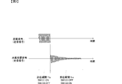
- FIG. 2 is a waveform diagram of an excitation signal and a resonance reverberation signal used in the temperature measurement system according to the first embodiment of the present invention.
- the temperature measurement system 1 includes a temperature measurement device 10 and a sensor element 20.
- the sensor element 20 is disposed in the part to be measured, and the temperature measuring device 10 is disposed at a distance that allows wireless communication with the sensor element 20 and is separated from the sensor element 20.
- the temperature measurement device 10 includes a control unit 110, a transmission amplifier 121, a first switch 131, a second switch 132, an inverting circuit 133, a reception amplifier 141, a down converter 142, an ADC 143, and an antenna 150.
- the control unit 110 includes an excitation control unit 111, a transmission signal generation unit 112, a reception intensity detection unit 113, a temperature detection unit 114, and a down-conversion signal generation unit 115.
- the sensor element 20 includes a resonance device 210 and a resonance side antenna 220.
- the transmission signal generation unit 112 of the control unit 110 is a voltage controlled oscillator or the like, generates a transmission signal based on the frequency channel information from the excitation signal control unit 111, and outputs the transmission signal to the transmission amplifier 121.
- the frequency channel information includes the center frequency of each frequency channel, frequency channel switching timing, and the like.
- the transmission signal is a sine wave having a predetermined frequency. The frequency of the transmission signal is switched for each frequency channel.
- the transmission amplifier 121 is a so-called power amplifier, which amplifies the transmission signal and outputs it to the first switch 131.
- the transmission / reception control signal from the excitation control unit 111 is input to the first switch 131.
- the transmission / reception control signal is composed of binary values that are contradictory between transmission and reception.
- the transmission / reception control signal is set to be Hi during the transmission period Ttx and Low during the reception period Trx.
- the timing at which the transmission / reception control signal becomes Hi and the timing at which the frequency channel is switched are synchronized.
- the first switch 131 is turned on when a Hi transmission / reception control signal is input, connects the output terminal of the transmission amplifier 121 to the antenna 150, and opens when a Low transmission / reception control signal is input, and the transmission amplifier 121. Between the output terminal of the antenna and the antenna 150. Thereby, as shown in FIG. 2, since the transmission signal is supplied to the antenna 150 only during the transmission period Ttx, the waveform is shaped into a pulse shape and becomes a pulse burst signal having a desired amplitude. This pulse burst signal becomes the excitation signal SpL1.
- the transmission signal generation unit 112, the transmission amplifier 121, and the first switch 131 having such a configuration correspond to the “excitation signal generation unit” of the present invention.
- the excitation signal generation unit sequentially generates and outputs the excitation signals of a plurality of frequency channels to the antenna 150 by switching the frequency of the transmission signal according to the frequency channel information and outputting it as described above.
- the excitation signal generation unit sequentially transmits the excitation signals of the respective channels with the reception period Trx for each excitation signal interposed therebetween. For example, after the channel CH1 excitation signal is transmitted in the transmission period Ttx, the reception period Trx for the channel CH1 excitation signal is opened, and the channel CH2 excitation signal is transmitted in the transmission period Ttx.
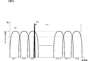
- FIG. 3 is a diagram showing the frequency spectrum distribution of the excitation signal.
- the horizontal axis represents frequency
- the vertical axis represents spectral intensity.
- each frequency channel is distributed so that a plurality of frequency channels each having a predetermined frequency bandwidth Fx are continuously distributed over the scanning frequency band Ftx.
- the center frequency of the excitation signal and the transmission period Ttx are set.
- the center frequency of the frequency band of each frequency channel is determined by the center frequency of the excitation signal, and the frequency bandwidth Fx is determined by the transmission period Ttx.
- the frequency channels of CH1 to CHn are set so that the bands partially overlap the scanning frequency band Ftx.
- the excitation signal of each frequency channel is set so as to overlap with the spectrum of the adjacent frequency channel at a frequency attenuated by 1 dB with respect to the peak level.
- the frequency width of each frequency channel that does not overlap is Fw, and the frequency width Fw of the frequency channels CH1 to CHn is set to cover the entire scanning frequency band Ftx.
- excitation signals of a plurality of frequency channels each having a different frequency band are output.
- the scanning frequency band Ftx is determined by the frequency band corresponding to the temperature range in which the resonance device 210 wants to perform temperature measurement.
- the transmission / reception control signal is input to the second switch 132 with its state inverted by the inverting circuit 133. Similarly to the first switch 131, the second switch 132 becomes conductive when a Hi transmission / reception control signal is input, and opens when a Low transmission / reception control signal is input.
- the second switch 132 is connected between the antenna 150 and the reception amplifier 141, and is opened when a Low transmission / reception control signal is input (when a Hi transmission / reception control signal is input to the first switch 131).
- a Low transmission / reception control signal is input (when a Hi transmission / reception control signal is input to the first switch 131).
- the space between the antenna 150 and the reception amplifier 141 is opened.
- the second switch 132 is prevented from being input to the reception amplifier 141 in an open state during the transmission period Ttx. Accordingly, the excitation signal SpL1 output from the first switch 131 is supplied only to the antenna 150 and is not input to the reception amplifier 141.
- the second switch 123 becomes conductive when a Hi transmission / reception control signal is input (when a Low transmission / reception control signal is input to the first switch 131), and connects the antenna 150 and the reception amplifier 141. As a result, the reception signal from the antenna 150 is input to the reception amplifier 141. At this time, since the first switch 131 is open, the reception signal is prevented from being input to the transmission amplifier 121.
- the antenna 150 and the resonance-side antenna 220 are, for example, loop antennas, and transmit and receive high-frequency signals to each other by being magnetically coupled.
- the antenna shape is not limited to the loop shape, and other shapes and coupling methods may be used.
- the excitation signal SpL1 of each frequency channel transmitted from the antenna 150 is received by the resonance side antenna 220 and supplied to the resonance device 210.
- the resonance device 210 is made of, for example, a crystal resonator, and when receiving the excitation signal SpL1 of each frequency channel and receiving the excitation signal Spf1 of the frequency channel including the resonance frequency of the resonance device 210, the resonance device 210 resonates at the resonance frequency and resonates.
- a reverberation signal Sfp1 is generated.
- the resonance reverberation signal Sfp1 is a signal for starting resonance with an amplitude corresponding to the signal intensity of the excitation signal SpL1 applied to the resonance device 210 at the start of resonance, and the amplitude is predetermined as time passes, as shown in FIG. It decays with the time constant of.
- the resonance frequency of the resonance reverberation signal Sfp1 is a resonance frequency corresponding to the temperature of the part under measurement where the resonance device 210 is installed.
- the resonance device 210 outputs the resonance reverberation signal Sfp1 to the resonance side antenna 220, and the resonance side antenna 220 transmits the resonance reverberation signal Sfp1 to the outside.
- Resonant reverberation signal Sfp ⁇ b> 1 is received by antenna 150.
- the second switch 132 When the resonant reverberation signal Sfp1 is received by the antenna 150, the second switch 132 is turned on and the first switch 131 is open as described above. Therefore, the resonance reverberation signal Sfp1 is input to the reception amplifier 141 via the second switch 132. Note that, during the reception period Trx of the frequency channel not including the resonant reverberation signal Sfp1, a reception signal made up of noise or the like is input to the reception amplifier 141.
- the reception amplifier 141 is a so-called LNA (low noise amplifier), amplifies the resonance reverberation signal Sfp1, and outputs the amplified signal to the down converter 142.
- the down converter 142 receives the down converter signal generated by the down conversion signal generation unit 115 of the control unit 110 together with the resonance reverberation signal Sfp1.
- the down converter 142 mixes the resonance reverberation signal Sfp1 and the down-conversion signal, and outputs a resonance reverberation signal Sfp1 having an intermediate frequency.
- the resonance reverberation signal Sfp1 having an intermediate frequency is input to an ADC (analog-digital conversion circuit) 143.
- the ADC 143 digitally samples the resonance reverberation signal Sfp ⁇ b> 1 and outputs it to the reception intensity detection unit 113 of the control unit 110.
- a reception signal made up of noise or the like is output to the reception intensity detection unit 113 via the reception amplifier 141, the down converter 142, and the ADC 143.
- the reception intensity detection unit 113 detects the signal intensity of the reception signal of each frequency channel, that is, the reception signal including the resonance reverberation signal Sfp1 or the reception signal not including the resonance reverberation signal Sfp1, and outputs the signal intensity to the excitation control unit 111.
- FIG. 4 is a waveform diagram showing the concept of detection of received signal strength.
- FIG. 4 shows the case of the resonant reverberation signal Sfp1.
- the reception intensity detection unit 113 sequentially performs amplitude peak detection on a waveform between a reception signal acquisition start timing, that is, a start time of the reception period Trx and a predetermined time ⁇ Tr. Then, the reception intensity detection unit 113 calculates a representative value Pw of the plurality of amplitude peaks.
- the representative value Pw is, for example, a median value.
- the representative value Pw becomes a high value equal to or higher than a predetermined level in the reception signal of the frequency channel in which the resonance reverberation signal Sfp1 exists.
- the received signal of the frequency channel in which the resonance reverberation signal Sfp1 does not exist has an extremely low value such as noise. Therefore, by detecting the representative value for detecting the intensity of the reception signal of each frequency channel using a plurality of amplitude peaks within the predetermined time ⁇ Tr, it can be prevented that the resonance reverberation signal is surely present. Further, even if noise with a high amplitude level is suddenly received, this influence can be suppressed and erroneous determination of the presence or absence of the resonance reverberation signal Sfp1 can be prevented.
- the excitation control unit 111 compares the representative value Pw of the received signal strength of each frequency channel, and detects the signal strength of the resonance reverberation signal Sfp1 and the frequency channel including the resonance reverberation signal Sfp1. For example, the excitation control unit 111 compares the representative value Pw of each frequency channel, and sets the highest representative value to the signal strength of the resonance reverberation signal Sfp1. Then, the frequency channel from which the highest representative value is obtained is set as the frequency channel including the resonance reverberation signal Sfp1.
- the excitation control unit 111 detects whether or not the signal intensity of the resonance reverberation signal Sfp1 is equal to or lower than the level adjustment threshold Thp.
- the excitation control unit 111 controls the signal strength of the excitation signal SpL1 to be lowered if the signal strength of the resonance reverberation signal Sfp1 is higher than the level adjustment threshold Thp. Specifically, the excitation control unit 111 performs control to shorten the transmission period Ttx of the transmission / reception control signal.
- FIG. 5A is a graph showing the relationship between the length (transmission time) of the transmission period Ttx and the peak power of the excitation signal.
- FIG. 5B is a graph showing the relationship between the peak power of the excitation signal and the frequency bandwidth of the excitation signal.
- the peak power of the excitation signal decreases by shortening the length of the transmission period (transmission time, pulse burst length).
- the peak power of the excitation signal is reduced, the power of the excitation signal applied to the resonance device 210 is reduced, so that the amplitude of the resonance reverberation signal Sfp1 generated by the resonance device 210 is also reduced.
- the frequency band widens as the power of the excitation signal decreases.
- the excitation control unit 111 repeats control for reducing the signal strength of the excitation signal until the signal strength of the resonance reverberation signal Sfp1 becomes equal to or lower than the level adjustment threshold Thp.
- the excitation control unit 111 detects that the signal strength of the resonance reverberation signal Sfp1 is equal to or lower than the level adjustment threshold Thp
- the excitation control unit 111 outputs a reception signal including the resonance reverberation signal Sfp1 to the temperature detection unit 114.
- the unit 113 is controlled. After the signal intensity of the resonant reverberation signal Sfp1 becomes equal to or lower than the level adjustment threshold Thp, the reception intensity detection unit 113 continuously outputs the reception signal to the temperature detection unit 114.
- the threshold value Thp for level adjustment is set to a value that hardly changes the resonance frequency of the resonance device 210 due to the excitation signal intensity.
- the resonance device 210 generates a resonance reverberation signal having a resonance frequency depending only on the sensed temperature by setting the excitation signal intensity to be equal to or lower than the level adjustment threshold Thp. Therefore, by detecting the resonance frequency of the resonance reverberation signal in a state where the excitation signal intensity is equal to or lower than the level adjustment threshold Thp in this way, it becomes possible to accurately detect the temperature of the measured part.
- the excitation control unit 111 sets the transmission signal generation unit 112 to generate only the transmission signal of the frequency channel including the resonance reverberation signal Sfp1. By performing such processing, it is possible to omit the transmission and reception periods of the excitation signal of the frequency channel that does not include the resonance reverberation signal Sfp1, and to speed up the temperature detection processing.
- the bandwidth of the frequency channel becomes wider as shown in FIG. Therefore, the frequency range in which the resonance reverberation signal Sfp1 is first detected is included in the frequency range after the excitation signal is lowered.
- the resonance frequency of the resonance reverberation signal Sfp1 deviates from an accurate resonance frequency under the condition that the excitation signal level to be measured is a predetermined value or less due to the high excitation signal level.
- the spectrum of the resonance reverberation signal Sfp1 after the excitation signal is reduced appears reliably. Therefore, the resonance reverberation signal Sfp1 can be acquired with certainty.
- the temperature detection unit 114 includes a frequency analysis unit 141 and a temperature calculation unit 142.
- the frequency analysis unit 141 converts a reception signal including the resonance reverberation signal Sfp1 on the time axis (hereinafter simply referred to as a resonance reverberation signal) into a signal on the frequency axis. Specifically, the frequency analysis unit 141 performs a Fourier transform on the input resonance reverberation signal. The frequency spectrum of the resonance reverberation signal obtained by the frequency analysis unit 141 is output to the temperature calculation unit 142.
- the temperature calculation unit 142 detects the spectrum peak of the frequency spectrum of the resonance reverberation signal.
- the temperature calculation unit 142 stores a frequency temperature relational expression or a frequency temperature relation table between the frequency spectrum peak and the temperature of the resonant device 210 in advance.
- the temperature detection unit 412 calculates the temperature sensed by the resonance device 210, that is, the temperature of the part to be measured, from the detected spectrum peak and the frequency temperature relational expression or the frequency temperature relation table.
- the excitation signal can be reduced so as not to affect the resonance frequency of the resonance device 210. Thereby, the temperature of a to-be-measured part can be measured correctly.
- FIG. 6 is a flowchart showing a temperature measurement method according to the first embodiment of the present invention.
- an excitation signal is transmitted to a resonant device using a plurality of frequency channels. Then, the reception signal of the frequency channel including the resonance reverberation signal is detected from the reception signals of the plurality of frequency channels (S101).
- the signal strength of the resonance reverberation signal is monitored, and the signal strength of the excitation signal is adjusted so that the signal strength of the resonance reverberation signal falls within the level adjustment threshold Thp (S102).
- the adjustment of the signal strength of the excitation signal is set according to the length of the transmission period Ttx.
- FIG. 7 is a flowchart showing a method for adjusting the signal strength of the excitation signal according to the first embodiment of the present invention.
- a representative value (hereinafter simply referred to as signal intensity of the resonance reverberation signal) Pw of the amplitude level of the resonance reverberation signal is detected (S211).
- the signal intensity Pw of the resonance reverberation signal is compared with the level adjustment threshold Thp. If the signal intensity Pw of the resonance reverberation signal is equal to or less than the level adjustment threshold Thp (S212: Yes), the signal intensity of the excitation signal is adjusted. do not do.
- the signal intensity Pw of the resonance reverberation signal is greater than the level adjustment threshold Thp (S212: No), the signal intensity of the excitation signal is adjusted (S213).
- FIG. 8 is a graph showing the dependency of the resonance frequency error on the communication distance between the temperature measuring device 10 and the sensor element 20.
- the horizontal axis is the communication distance
- the vertical axis is the error.
- the error is calculated based on the resonance frequency of the communication distance DISa.
- the solid line shows the case of the present configuration
- the broken line shows the case of the conventional configuration (same as FIG. 11).
- the detected resonance frequency hardly changes even if the communication distance changes. Thereby, the temperature of the part to be measured can be accurately measured without being affected by the communication distance.
- the signal strength of the excitation signal of each frequency channel to be transmitted first is the sensor element 20 and the temperature measuring device 10 assumed in the measurement system using the configuration. Set to the maximum signal strength based on the maximum communication distance between. Thereby, a resonance reverberation signal can be acquired more reliably. Also, it is possible to set the signal strength of the appropriate excitation signal at a higher speed than when starting from a minimum value or an intermediate value that can be considered.
- the signal intensity of the appropriate excitation signal is the maximum value that does not affect the resonance frequency of the resonance device, and is a value corresponding to the case where the signal intensity of the resonance reverberation signal matches the level adjustment threshold Thp.
- FIG. 9 is a configuration diagram of a temperature measurement system according to the second embodiment of the present invention.
- the temperature measurement system 1A of the present embodiment is different from the temperature measurement system 1 shown in the first embodiment only in the transmission amplifier and the excitation control unit, and other configurations are shown in the first embodiment. This is the same as the temperature measurement system 1.
- the transmission amplifier 121A of the temperature measurement device 10A of the temperature measurement system 1A is an amplifier capable of gain adjustment.
- the excitation control unit 111A of the control unit 110A of the temperature measurement system 1A performs gain adjustment control of the transmission amplifier 121A as well as frequency channel switching control and transmission / reception control signal control.
- the excitation control unit 111A shortens the transmission time and decreases the gain of the transmission amplifier 121A. Thereby, the adjustment range of the signal strength of the excitation signal can be increased while maintaining the adjustment accuracy of the signal strength of the excitation signal.
- a transmission amplifier that cannot adjust the gain and a variable resistor connected to the output terminal of the transmission amplifier may be used. In this case, the variable resistance value may be changed.
- the reception intensity detection unit 113 and the excitation control unit 111 acquire the signal intensity Pw a plurality of times, control the signal intensity of the excitation signal from the average value, Resonance reverberation signal output start control may be performed.
- the average value a more accurate resonance frequency can be detected, and the temperature can be measured more accurately.
- the temperature measurement system and the temperature measurement device have been described as examples.
- a physical quantity measurement system that measures physical quantities other than temperature, such as magnetic field strength (magnetic flux), by changing the resonance frequency of the resonator,
- the configuration and processing described above can also be applied to the physical quantity measuring device.
Landscapes
- Physics & Mathematics (AREA)
- General Physics & Mathematics (AREA)
- Chemical & Material Sciences (AREA)
- Crystallography & Structural Chemistry (AREA)
- Engineering & Computer Science (AREA)
- Computer Networks & Wireless Communication (AREA)
- Acoustics & Sound (AREA)
- Arrangements For Transmission Of Measured Signals (AREA)
Abstract
送信信号生成部(112)、送信アンプ(121)、第1スイッチ(131)からなる励振信号生成部は、それぞれに異なる周波数帯域からなる各周波数チャンネルの励振信号を生成し、アンテナ(150)から送信する。アンテナ(150)で受信された各周波数チャンネルの受信信号は、受信強度検出部(113)に入力される。受信強度検出部(113)は、各周波数チャンネルの受信信号から共振残響信号を検出し、その信号強度を検出する。励振制御部(111)は、共振残響信号の信号強度がレベル調整用閾値(Thp)以下になるように、励振信号の信号強度を調整する制御を、励振信号生成部に実行する。共振残響信号の信号強度がレベル調整用閾値(Thp)以下になると、温度検出部(114)は、共振残響信号を周波数解析して、周波数スペクトルピークから物理量(温度)を検出する。
Description
本発明は、共振子の共振周波数が温度や磁界強度等の物理量に依存して変化することを利用して、被測定部の物理量を検出する物理量測定システム、および当該物理量測定システムに利用する物理量測定装置に関する。
従来、無線を利用して、遠隔位置の被測定部の物理量を検出するシステムが各種考案されている。その一種として、遠隔位置の温度を測定する無線式温度測定システムがある。無線式温度測定システムは、例えば特許文献1に記載のように、温度測定部に配置されてセンサ装置と、当該センサ装置から離間した位置に配置された温度測定装置とによって、構成される。センサ装置と温度測定装置とは、無線通信可能な構成からなる。
このような無線式温度測定システムにおいて、センサ側アンテナと共振子とでセンサ装置を構成するものがある。この場合、温度測定装置は、センサ装置の共振子に対して励振信号を送信する。共振子は、共振周波数に温度特性を有するため、共振子が配置された被検温部の温度に応じた共振周波数の共振残響信号を発生する。共振残響信号は、センサ側アンテナを介して温度測定装置に送信される。
温度測定装置は、受信した共振残響信号の周波数を検出することで、共振子の感知した温度を算出している。
このような共振周波数の変化は、温度に限るものではなく、磁界強度等の他の物理量によって生じるので、共振周波数の変化から被測定部の他の物理量を測定することもできる。
しかしながら、共振子は、共振周波数に温度特性を有するだけでなく、励振強度によって共振周波数が変化する。図10は、水晶振動子の励振強度による共振周波数変化を示すグラフである。図10において、横軸は励振レベル(励振強度)であり、縦軸は共振周波数の変化量である。なお、縦軸の共振周波数の変化量は、励振レベルが-20[dBm]の共振周波数を基準とした変化量である。
図10に示すように、励振強度が強くなるにしたがって、共振周波数が大きく変化していく。また、励振強度が強くなるほど、共振周波数のバラツキが大きくなる。
また、図11は通信距離と共振周波数の誤差を示すグラフである。図11において、横軸は温度測定装置とセンサ装置との通信距離であり、縦軸は共振周波数の誤差である。なお、縦軸の共振周波数の誤差は、図11に示す通信距離DISaの位置の共振周波数を基準としている。
図11に示すように、通信距離が短くなると、共振周波数の誤差が大きくなる。これは、通信距離が短くなるほど、無線通信による励振信号の減衰が小さくなり、共振子に印加される励振信号の強度が高くなるからである。このようなことから、通信距離DISaを規定して、当該通信距離DISaでの励振強度が問題無いように調整されていても、通信距離が短くなってしまうと、共振周波数がずれてしまう。したがって、使用態様に応じて共振周波数がずれてしまうことがある。
そして、このように共振周波数がずれてしまうと、共振周波数に基づいて温度を算出しているので、算出温度もずれてしまう。したがって、被検温部の温度を測定精度が劣化する。なお、他の物理量の場合も同様に、被測定部の物理量の測定精度が劣化する。
本発明の目的は、被測定部の物理量を高精度に測定できる物理量測定システムおよびこの物理量測定システムに利用する物理量測定装置を提供することにある。
この発明は、物理量測定装置に関するものであり、次の特徴を有する。物理量測定装置は、励振信号生成部、アンテナ、受信強度検出部、物理量検出部、および励振制御部を備える。励振信号生成部は、所定周波数のバースト波からなる励振信号を生成する。アンテナは、励振信号を送波し、励振信号に基づく受信信号を受波する。受信強度検出部は、励振信号による共振残響信号を受信信号から検出し、該共振残響信号の信号強度を検出する。物理量検出部は、共振残響信号の共振周波数から所定の物理量を検出する。励振制御部は、共振残響信号の信号強度が信号強度閾値よりも高いことを検出すると、励振信号の信号強度を低下させる。
この構成では、物理量による共振周波数が励振信号の信号強度によって誤差を有さないように、励振信号の信号強度が調整される。
また、この発明の物理量測定装置は、次の構成を備えることが好ましい。励振信号生成部は、それぞれに異なる中心周波数で所定の周波数帯域幅からなる複数の周波数チャンネルの励振信号を生成する。受信強度検出部は、各周波数チャンネルの励振信号による受信信号の信号強度を比較して、共振残響信号を検出する。
この構成では、複数の周波数帯域に分割された受信信号を用いて、共振残響信号を確実且つ正確に検出することができる。
また、この発明の物理量測定装置の励振制御部は、共振残響信号を検出すると、該共振残響信号の周波数を含む周波数チャンネルの励振信号のみを生成するように、励振信号生成部を制御することが好ましい。
この構成では、複数回の共振残響信号を高速に取得することができる。
また、この発明の物理量測定装置の物理量検出部は、共振残響信号の信号強度が信号強度閾値以下になった時点から共振周波数の検出を行うことが好ましい。
この構成では、不要な共振周波数の検出処理を防止できる。
また、この発明の物理量測定装置の励振制御部は、励振信号の送信時間長によって励振信号の信号強度を調整することができる。
この構成では、励振信号の信号強度の具体的な調整方法の一例を示している。
また、この発明の物理量測定装置の励振制御部は、励振信号の振幅レベルによって励振信号の信号強度を調整することができる。
この構成でも、励振信号の信号強度の具体的な調整方法の一例を示している。そして、これら送信時間長と振幅レベルを組み合わせて励振信号の信号強度を調整することもできる。
また、この発明の物理量測定装置の励振信号生成部は、最初の励振信号の強度を、共振残響信号の信号強度を調整し終わるまでに送信される励振信号群の中で最大にすることが好ましい。
この構成では、共振周波数に影響を与えない最大強度に励振信号の信号強度を調整する処理を、高速に行うことができる。
また、この発明の物理量測定装置の受信強度検出部は、受信信号の時間軸上に並べた最初から所定期間までの振幅レベルによって決定することが好ましい。
この構成では、受信信号の信号強度、すなわち共振残響信号の信号強度を、比較的安定して正確に検出することができる。
また、この発明の物理量測定システムは、上述の物理量測定装置と、励振信号を受けて励振して物理量に応じた周波数で共振することで共振残響信号を発生する共振子、および、該共振子に接続する共振子側アンテナを備えるセンサ素子と、を備える。
この構成では、上述の構成からなる物理量測定装置を用いて、被測定部の物理量を正確に測定する物理量測定システムを実現することができる。
また、この発明の物理量測定システムの共振子は水晶振動子で実現することができる。この構成では、共振子の具体的な一例を示している。
また、この発明の物理量測定システムでは、物理量は温度であってもよい。この構成では、この物理量測定システムで測定する物理量の具体的な一例を示している。
この発明よれば、使用態様に影響されることなく、被検温部の温度を高精度に測定することができる。
本発明の第1の実施形態に係る物理量測定システムについて、図を参照して説明する。なお、本実施形態では被測定部の温度を測定する温度測定システムについて説明する。
図1は、本発明の第1の実施形態に係る温度測定システムの構成図である。図2は本発明の第1の実施形態に係る温度測定システムで用いる励振信号および共振残響信号の波形図である。
温度測定システム1は、温度測定装置10、センサ素子20を備える。センサ素子20は、被測定部に配置され、温度測定装置10は、センサ素子20に対して無線通信可能な距離で、センサ素子20に対して離間して配置されている。
温度測定装置10は、制御部110、送信アンプ121、第1スイッチ131、第2スイッチ132、反転回路133、受信アンプ141、ダウンコンバータ142、ADC143、および、アンテナ150を備える。制御部110は、励振制御部111、送信信号生成部112、受信強度検出部113、温度検出部114、および、ダウンコンバート用信号発生部115を備える。センサ素子20は、共振デバイス210と共振側アンテナ220とを備える。
制御部110の送信信号生成部112は、電圧制御発振器等であり、励振信号制御部111からの周波数チャンネル情報等に基づいて送信信号を生成して、送信アンプ121に出力する。周波数チャンネル情報は、各周波数チャンネルの中心周波数や周波数チャンネルの切り替えタイミング等を含む。送信信号は、所定周波数の正弦波からなる。送信信号の周波数は、周波数チャンネル毎に切り替えられる。送信アンプ121は、所謂パワーアンプであり、送信信号を増幅して、第1スイッチ131に出力する。
第1スイッチ131には、励振制御部111からの送受制御信号が入力される。送受制御信号は、送信時と受信時とで相反する二値からなる。例えば、送受制御信号は、送信期間TtxでHiであり、受信期間TrxでLowになるように設定されている。送受制御信号のHiになるタイミングと周波数チャンネルの切り替わるタイミングは同期している。
第1スイッチ131は、Hiの送受制御信号が入力された時に導通して、送信アンプ121の出力端をアンテナ150に接続し、Lowの送受制御信号が入力された時に開放して、送信アンプ121の出力端とアンテナ150の間を開放する。これにより、図2に示すように、送信信号は送信期間Ttxの期間だけアンテナ150側に供給されるのでパルス状に波形成形され、所望の振幅を有するパルスバースト信号となる。このパルスバースト信号が励振信号SpL1となる。
このような構成からなる送信信号生成部112、送信アンプ121、第1スイッチ131が、本発明の「励振信号生成部」に相当する。そして、この励振信号生成部は、上述のように周波数チャンネル情報により送信信号の周波数を切り替えて出力することで、複数の周波数チャンネルの励振信号を、順次生成してアンテナ150に出力する。この際、励振信号生成部は、各チャンネルの励振信号を、それぞれの励振信号に対する受信期間Trxを挟んで、順次送信する。例えば、チャンネルCH1の励振信号を送信期間Ttxで送信した後、チャンネルCH1の励振信号に対する受信期間Trxをあけ、チャンネルCH2の励振信号を送信期間Ttxで送信する。
図3は励振信号の周波数スペクトル分布を示す図である。図3の横軸は周波数であり、縦軸はスペクトル強度である。本実施形態の励振信号生成部では、図3に示すように、走査周波数帯域Ftxに亘り、それぞれに所定の周波数帯域幅Fxを有する複数の周波数チャンネルを連続して分布させるように、各周波数チャンネルの励振信号の中心周波数および送信期間Ttxが設定されている。各周波数チャンネルの周波数帯域の中心周波数は、励振信号の中心周波数で決定され、周波数帯域幅Fxは送信期間Ttxで決定される。
具体的に図3に示す場合であれば、走査周波数帯域Ftxに対して、部分的に帯域が重なるように、CH1~CHn(nは所定の整数)の周波数チャンネルが設定されている。そして、各周波数チャンネルの励振信号は、ピークレベルに対して1dB減衰した周波数で、隣り合う周波数チャンネルのスペクトルと重なり合うように設定されている。この重なり合わない各周波数チャンネルの周波数幅がFwであり、CH1~CHnの周波数チャンネルの周波数幅Fwによって走査周波数帯域Ftxの全域がカバーされるように設定されている。
これにより、それぞれ異なる周波数帯域を有する複数の周波数チャンネルの励振信号が出力される。なお、走査周波数帯域Ftxは、共振デバイス210によって温度測定を行いたい温度範囲に対応する周波数帯域によって決定する。
このような励振信号の出力の際、第2スイッチ132には、送受制御信号が反転回路133によって状態反転されて入力される。第2スイッチ132も、第1スイッチ131と同様に、Hiの送受制御信号が入力された時に導通になり、Lowの送受信制御信号が入力された時に開放になる。
第2スイッチ132は、アンテナ150と受信アンプ141との間に接続されており、Lowの送受制御信号が入力された時(第1スイッチ131にHiの送受制御信号が入力された時)に開放してアンテナ150と受信アンプ141との間を開放する。これにより、第2スイッチ132は、送信期間Ttxで開放に、逓信信号が受信アンプ141に入力されることを防止する。これにより、第1スイッチ131から出力される励振信号SpL1は、アンテナ150のみに供給され、受信アンプ141には入力されない。
なお、第2スイッチ123は、Hiの送受制御信号が入力された時(第1スイッチ131にLowの送受制御信号が入力された時)導通してアンテナ150と受信アンプ141とを接続する。これにより、アンテナ150からの受信信号は、受信アンプ141に入力される。この際、第1スイッチ131は開放であるので、受信信号が送信アンプ121に入力されることを防止する。
アンテナ150と共振側アンテナ220は、例えばループ状アンテナであり、磁界結合することにより、互いの高周波信号を送受信する。なお、アンテナ形状はループ状に限るものではなく、他の形状、結合方式であってもよい。
アンテナ150から送信された各周波数チャンネルの励振信号SpL1は、共振側アンテナ220で受信され、共振デバイス210に供給される。
共振デバイス210は、例えば水晶振動子からなり、各周波数チャンネルの励振信号SpL1を受けて、共振デバイス210の共振周波数を含む周波数チャンネルの励振信号Spf1を受けた時に、当該共振周波数で共振し、共振残響信号Sfp1を生成する。共振残響信号Sfp1は、共振開始時に共振デバイス210に印加された励振信号SpL1の信号強度に応じた振幅で共振を開始する信号であり、その振幅は、図2に示すように、時間経過とともに所定の時定数で減衰していく。
ここで、共振デバイス210である水晶振動子は、共振周波数に温度依存性がある。したがって、共振残響信号Sfp1の共振周波数は、共振デバイス210が設置される被測定部の温度に応じた共振周波数となる。
共振デバイス210は共振残響信号Sfp1を共振側アンテナ220に出力し、共振側アンテナ220は、共振残響信号Sfp1を外部へ送信する。共振残響信号Sfp1は、アンテナ150で受信される。
共振残響信号Sfp1が、アンテナ150で受信される時点では、上述のように、第2スイッチ132が導通し、第1スイッチ131が開放している。したがって、共振残響信号Sfp1は、第2スイッチ132を介して、受信アンプ141に入力される。なお、共振残響信号Sfp1を含まない周波数チャンネルの受信期間Trxは、ノイズ等からなる受信信号が受信アンプ141に入力される。
受信アンプ141は、所謂LNA(低雑音アンプ)であり、共振残響信号Sfp1を増幅して、ダウンコンバータ142に出力する。ダウンコンバータ142には、共振残響信号Sfp1とともに、制御部110のダウンコンバート用信号発生部115で生成されたダウンコンバータ用信号が入力される。ダウンコンバータ142は、共振残響信号Sfp1とダウンコンバート用信号とをミキシングすることで、中間周波数の共振残響信号Sfp1を出力する。中間周波数化された共振残響信号Sfp1は、ADC(アナログデジタル変換回路)143に入力される。ADC143は、共振残響信号Sfp1をデジタルサンプリングして、制御部110の受信強度検出部113に出力する。なお、共振残響信号が含まれない周波数チャンネルの受信期間Trxは、ノイズ等からなる受信信号が、受信アンプ141、ダウンコンバータ142、ADC143を介して受信強度検出部113に出力される。
受信強度検出部113は、各周波数チャンネルの受信信号、すなわち共振残響信号Sfp1を含む受信信号もしくは共振残響信号Sfp1が含まれていない受信信号の信号強度を検出し、励振制御部111に出力する。
図4は、受信信号強度の検出概念を示す波形図である。図4は共振残響信号Sfp1の場合を示す。図4に示すように、受信強度検出部113は、受信信号の取得開始タイミング、すなわち受信期間Trxの開始タイミングから所定時間ΔTrの間の波形に対して振幅のピーク検出を順次行う。そして、受信強度検出部113は、これら複数の振幅ピークの代表値Pwを算出する。代表値Pwとしては、例えば中央値である。このような処理を行えば、共振残響信号Sfp1が存在する周波数チャンネルの受信信号では、代表値Pwは所定レベル以上の高い値になる。一方、共振残響信号Sfp1が存在しない周波数チャンネルの受信信号では、ノイズ程度の極低い値となる。したがって、所定時間ΔTr内の複数の振幅ピークを用いて、各周波数チャンネルの受信信号の強度検出用の代表値を検出することで、確実に共振残響信号が存在すると判断することを防止できる。また、振幅レベルの高いノイズが突発的に受信されても、この影響を抑圧し、共振残響信号Sfp1の有無の誤判定を防止できる。
励振制御部111は、各周波数チャンネルの受信信号強度の代表値Pwを比較し、共振残響信号Sfp1の信号強度、および、当該共振残響信号Sfp1を含む周波数チャンネルの検出を行う。例えば、励振制御部111は、各周波数チャンネルの代表値Pwを比較し、最も高い代表値を、共振残響信号Sfp1の信号強度に設定する。そして、この最も高い代表値が得られた周波数チャンネルを、共振残響信号Sfp1を含む周波数チャンネルに設定する。
励振制御部111は、共振残響信号Sfp1の信号強度が、レベル調整用閾値Thp以下であるかどうかを検出する。励振制御部111は、共振残響信号Sfp1の信号強度がレベル調整用閾値Thpよりも高ければ、励振信号SpL1の信号強度を低下させるように制御する。具体的には、励振制御部111は、送受制御信号の送信期間Ttxの時間を短くするように制御する。図5(A)は、送信期間Ttxの長さ(送信時間)と励振信号のピークパワーとの関係を示すグラフである。図5(B)は、励振信号のピークパワーと励振信号の周波数帯域幅との関係を示すグラフである。
図5(A)に示すように、送信期間の長さ(送信時間、パルスバースト長)を短くすることで、励振信号のピークパワーは低下する。励振信号のピークパワーが低下すると、共振デバイス210に印加される励振信号のパワーが低下するので、共振デバイス210が生じる共振残響信号Sfp1の振幅も低下する。なお、この際、励振信号のパワーの低下に伴って周波数帯域は広がる。
励振制御部111は、共振残響信号Sfp1の信号強度がレベル調整用閾値Thp以下になるまで、励振信号の信号強度を低下させる制御を繰り返す。励振制御部111は、共振残響信号Sfp1の信号強度がレベル調整用閾値Thp以下になったことを検出すると、共振残響信号Sfp1を含む受信信号を温度検出部114に出力するように、受信強度検出部113を制御する。共振残響信号Sfp1の信号強度がレベル調整用閾値Thp以下になって以降は、受信強度検出部113は、受信信号を継続的に温度検出部114に出力する。
この際、レベル調整用閾値Thpを、励振信号強度による共振デバイス210の共振周波数の変化が殆ど生じない値に設定する。これにより、励振信号強度をレベル調整用閾値Thp以下にすることで、共振デバイス210は、感知温度のみに依存した共振周波数の共振残響信号を生成する。したがって、このように励振信号強度をレベル調整用閾値Thp以下にした状態の共振残響信号の共振周波数を検出することで、被測定部の温度を正確に検出することが可能になる。
なお、励振制御部111は、送信信号生成部112に対して、共振残響信号Sfp1を含む周波数チャンネルの送信信号のみを生成するように設定する。このような処理を行うことで、共振残響信号Sfp1を含まない周波数チャンネルの励振信号の送信、および受信期間を省略でき、温度検出処理をより高速化することができる。
そして、このような励振信号を所定レベル以下に低下させる処理を行うことで、上述の図5(B)に示すように、周波数チャンネルの帯域幅は広くなっていく。したがって、最初に共振残響信号Sfp1が検出された周波数範囲は、励振信号を低下させた後の周波数範囲に含まれる。これにより、励振信号のレベルが高いことにより共振残響信号Sfp1の共振周波数が、測定対象とする励振信号のレベルが所定値以下の条件下での正確な共振周波数からずれていても、低下後の周波数範囲内に、励振信号低下後の共振残響信号Sfp1のスペクトルが確実に現れる。したがって、共振残響信号Sfp1を確実に取得することができる。
温度検出部114は、周波数解析部141および温度算出部142を備える。周波数解析部141は、時間軸上の共振残響信号Sfp1を含む受信信号(以下、単に共振残響信号とする。)を、周波数軸上の信号に変換する。具体的には、周波数解析部141は、入力された共振残響信号をフーリエ変換する。周波数解析部141で得られた共振残響信号の周波数スペクトルを、温度算出部142に出力する。
温度算出部142は、共振残響信号の周波数スペクトルのスペクトルピークを検出する。温度算出部142は、周波数スペクトルピークと共振デバイス210の温度との周波数温度関係式もしくは周波数温度関係テーブルを予め記憶している。温度検出部412は、検出したスペクトルピークと、上記周波数温度関係式もしくは周波数温度関係テーブルと、から共振デバイス210が感知した温度、すなわち被測定部の温度を算出する。
以上のように、本実施形態の構成を用いることで、共振デバイス210の共振周波数に影響を与えないように励振信号を低下させることができる。これにより、被測定部の温度を正確に測定することができる。
以上のような処理は、上述の構成に限るものではなく、次に示すフローを実現できる構成であればよい。図6は、本発明の第1の実施形態に係る温度測定方法を示すフローチャートである。
まず、本実施形態の温度測定方法では、複数の周波数チャンネルで励振信号を、共振デバイスに送信する。そして、複数の周波数チャンネルの受信信号から共振残響信号を含む周波数チャンネルの受信信号を検出する(S101)。
次に、共振残響信号の信号強度をモニタし、当該共振残響信号の信号強度がレベル調整用閾値Thp以下に収まるように、励振信号の信号強度を調整する(S102)。この際、励振信号の信号強度の調整は、送信期間Ttxの長さによって設定する。
次に、レベル調整用閾値Thp以下になった共振残響信号を周波数解析する(S103)。そして、周波数解析結果に基づいて、共振デバイスが感知した温度を算出する(S104)。
なお、励振信号の信号強度の調整は、図7に示すフローにより実現される。図7は、本発明の第1の実施形態に係る励振信号の信号強度調整方法を示すフローチャートである。
まず、共振残響信号を含む周波数チャンネルを検出すると、当該共振残響信号の振幅レベルの代表値(以下、単に共振残響信号の信号強度)Pwを検出する(S211)。次に、共振残響信号の信号強度Pwをレベル調整用閾値Thpと比較し、共振残響信号の信号強度Pwがレベル調整用閾値Thp以下であれば(S212:Yes)、励振信号の信号強度は調整しない。
共振残響信号の信号強度Pwがレベル調整用閾値Thpよりも大きければ(S212:No)、励振信号の信号強度を調整する(S213)。
この後、共振残響信号を含む周波数チャンネルの励振信号のみを送信し(S214)、この共振残響信号の信号強度を検出する(S215)。
ここで、共振残響信号の信号強度Pwがレベル調整用閾値Thpよりも大きければ(S216:No)、励振信号の信号強度の調整を繰り返す(S213)。
そして、共振残響信号の信号強度Pwがレベル調整用閾値Thp以下になったことを検出する(S216:Yes)と、励振信号の信号強度の調整を終了する。
以上の構成および処理を行った場合、図8に示すような結果が得られた。図8は温度測定装置10とセンサ素子20との通信距離に対する共振周波数の誤差の依存性を示すグラフである。図8において、横軸は通信距離であり、縦軸は誤差である。誤差は通信距離DISaの共振周波数を基準に算出されている。また、図8において実線が本願構成の場合を示し、破線が従来構成(図11と同じ)の場合を示す。図8に示すように、本実施形態の構成及び処理を用いることで、通信距離が変化しても、検出する共振周波数は殆ど変化しない。これにより、通信距離に影響されることなく、被測定部の温度を正確に測定することができる。
なお、上述の説明では、具体的に示していなかったが、最初に送信する各周波数チャンネルの励振信号の信号強度は、当該構成を利用する測定系において想定されるセンサ素子20と温度測定装置10の間の最大通信距離に基づく最大信号強度に設定する。これにより、より確実に共振残響信号を取得することができる。また、考え得る最小値や中間値から開始するよりも、高速に適正な励振信号の信号強度に設定することができる。なお、適正な励振信号の信号強度とは、共振デバイスの共振周波数の影響を与えない最大値であり、共振残響信号の信号強度がレベル調整用閾値Thpと一致する場合に対応する値である。
次に、本発明の第2の実施形態に係る物理量測定システムについて、図を参照して説明する。なお、本実施形態でも被測定部の温度を測定する温度測定システムについて説明する。図9は、本発明の第2の実施形態に係る温度測定システムの構成図である。
本実施形態の温度測定システム1Aは、第1の実施形態に示した温度測定システム1に対して、送信アンプと励振制御部とが異なるのみで、他の構成は第1の実施形態に示した温度測定システム1と同じである。
温度測定システム1Aの温度測定装置10Aの送信アンプ121Aは、ゲイン調整が可能なアンプである。温度測定システム1Aの制御部110Aの励振制御部111Aは、周波数チャンネルの切り替え制御、送受信制御信号の制御とともに、送信アンプ121Aのゲイン調整制御も行う。励振制御部111Aは、共振残響信号の信号強度がレベル調整用閾値Thpよりも高いと、送信時間を短くするとともに、送信アンプ121Aのゲインを低下させる。これにより、励振信号の信号強度の調整精度を維持したまま、励振信号の信号強度の調整幅を大きくすることができる。なお、送信アンプ121Aに替えて、ゲイン調整できない送信アンプと、この送信アンプの出力端子に接続する可変抵抗を用いてもよい。この場合、可変抵抗値を変化させればよい。
なお、上述の各実施形態において、受信強度検出部113および励振制御部111は、複数回の信号強度Pwを取得し、その平均値から励振信号の信号強度の制御や、温度検出部114への共振残響信号の出力開始制御を行ってもよい。このように、平均値を用いることで、より正確な共振周波数を検出することができ、より正確に温度を測定することができる。
また、上述の各実施形態では、温度測定システムおよび温度測定装置を例に説明したが、磁界強度(磁束)等の温度以外の物理量を、共振子の共振周波数の変化によって測定する物理量測定システムや物理量測定装置についても、上述の構成及び処理を適用することができる。
1,1A:温度測定システム、
10,10A:温度測定装置、
110,110A:制御部、
111,111A:励振制御部、
112:送信信号生成部、
113:受信強度検出部、
114:温度検出部、
115:ダウンコンバート用信号発生部、
121,121A:送信アンプ、
131:第1スイッチ、
132:第2スイッチ、
133:反転回路、
141:受信アンプ、
142:ダウンコンバータ、
143:ADC(アナログデジタル変換回路)、
150:アンテナ、
20:センサ素子、
210:共振デバイス、
220:共振側アンテナ
10,10A:温度測定装置、
110,110A:制御部、
111,111A:励振制御部、
112:送信信号生成部、
113:受信強度検出部、
114:温度検出部、
115:ダウンコンバート用信号発生部、
121,121A:送信アンプ、
131:第1スイッチ、
132:第2スイッチ、
133:反転回路、
141:受信アンプ、
142:ダウンコンバータ、
143:ADC(アナログデジタル変換回路)、
150:アンテナ、
20:センサ素子、
210:共振デバイス、
220:共振側アンテナ
Claims (11)
- 所定周波数のバースト波からなる励振信号を生成する励振信号生成部と、
前記励振信号を送波し、前記励振信号に基づく受信信号を受波するアンテナと、
前記励振信号による共振残響信号を前記受信信号から検出し、該共振残響信号の信号強度を検出する受信強度検出部と、
前記共振残響信号の共振周波数から所定の物理量を検出する物理量検出部と、
前記共振残響信号の信号強度が信号強度閾値よりも高いことを検出すると、前記励振信号の信号強度を低下させる励振制御部と、
を備えた物理量測定装置。 - 前記励振信号生成部は、それぞれに異なる中心周波数で所定の周波数帯域幅からなる複数の周波数チャンネルの励振信号を生成し、
前記受信強度検出部は、各周波数チャンネルの励振信号による受信信号の信号強度を比較して、前記共振残響信号を検出する、
請求項1に記載の物理量測定装置。 - 前記励振制御部は、前記共振残響信号を検出すると、該共振残響信号の周波数を含む周波数チャンネルの励振信号のみを生成するように、前記励振信号生成部を制御する、
請求項2に記載の物理量測定装置。 - 前記物理量検出部は、
前記共振残響信号の信号強度が前記信号強度閾値以下になった時点から、前記共振周波数の検出を行う、
請求項1乃至請求項3のいずれかに記載の物理量測定装置。 - 前記励振制御部は、前記励振信号の送信時間長によって前記励振信号の信号強度を調整する、
請求項1乃至請求項4のいずれかに記載の物理量測定装置。 - 前記励振制御部は、前記励振信号の振幅レベルによって前記励振信号の信号強度を調整する、
請求項1乃至請求項5のいずれかに記載の物理量測定装置。 - 前記励振信号生成部は、最初の励振信号の強度を、前記共振残響信号の信号強度を調整し終わるまでに送信される励振信号群の中で最大にする、
請求項1乃至請求項6のいずれかに記載の物理量測定装置。 - 前記受信強度検出部は、
前記受信信号の時間軸上に並べた最初から所定期間までの振幅レベルによって決定する、
請求項1乃至請求項7のいずれかに記載の物理量測定装置。 - 請求項1乃至請求項8のいずれかに記載の物理量測定装置と、
前記励振信号を受けて励振し、物理量に応じた周波数で共振し、前記共振残響信号を発生する共振子、および、該共振子に接続する共振子側アンテナを備えるセンサ素子と、
を備えた、物理量測定システム。 - 前記共振子は水晶振動子である、請求項9に記載の物理量測定システム。
- 前記物理量は温度である、請求項9または請求項10に記載の物理量測定システム。
Priority Applications (2)
| Application Number | Priority Date | Filing Date | Title |
|---|---|---|---|
| JP2015501294A JP5928652B2 (ja) | 2013-02-25 | 2013-12-19 | 物理量測定装置、物理量測定システム |
| US14/833,618 US10060800B2 (en) | 2013-02-25 | 2015-08-24 | Physical quantity measuring device and physical quantity measuring system |
Applications Claiming Priority (2)
| Application Number | Priority Date | Filing Date | Title |
|---|---|---|---|
| JP2013-034137 | 2013-02-25 | ||
| JP2013034137 | 2013-02-25 |
Related Child Applications (1)
| Application Number | Title | Priority Date | Filing Date |
|---|---|---|---|
| US14/833,618 Continuation US10060800B2 (en) | 2013-02-25 | 2015-08-24 | Physical quantity measuring device and physical quantity measuring system |
Publications (1)
| Publication Number | Publication Date |
|---|---|
| WO2014129071A1 true WO2014129071A1 (ja) | 2014-08-28 |
Family
ID=51390883
Family Applications (1)
| Application Number | Title | Priority Date | Filing Date |
|---|---|---|---|
| PCT/JP2013/084012 WO2014129071A1 (ja) | 2013-02-25 | 2013-12-19 | 物理量測定装置、物理量測定システム |
Country Status (3)
| Country | Link |
|---|---|
| US (1) | US10060800B2 (ja) |
| JP (1) | JP5928652B2 (ja) |
| WO (1) | WO2014129071A1 (ja) |
Cited By (1)
| Publication number | Priority date | Publication date | Assignee | Title |
|---|---|---|---|---|
| KR20200018020A (ko) * | 2018-08-10 | 2020-02-19 | 국방과학연구소 | 데이터 축약 통합 계측 장치, 이의 제어 방법, 그리고 이 방법을 저장한 컴퓨터 판독 가능 저장 매체 |
Citations (3)
| Publication number | Priority date | Publication date | Assignee | Title |
|---|---|---|---|---|
| JPH03238594A (ja) * | 1990-02-15 | 1991-10-24 | Sekisui Chem Co Ltd | 火災感知装置 |
| JP2004295431A (ja) * | 2003-03-26 | 2004-10-21 | Sankyo Seiki Mfg Co Ltd | 磁気式センサ装置 |
| JP2012168155A (ja) * | 2010-09-24 | 2012-09-06 | Murata Mfg Co Ltd | 無線式体温計および無線式体温測定システム |
Family Cites Families (2)
| Publication number | Priority date | Publication date | Assignee | Title |
|---|---|---|---|---|
| JP2011137737A (ja) * | 2009-12-28 | 2011-07-14 | Fukuda Crystal Laboratory | 無線測定装置、および無線温度測定システム |
| US8348504B2 (en) * | 2010-05-12 | 2013-01-08 | Wireless Sensor Technologies, Llc | Wireless temperature measurement system and methods of making and using same |
-
2013
- 2013-12-19 WO PCT/JP2013/084012 patent/WO2014129071A1/ja active Application Filing
- 2013-12-19 JP JP2015501294A patent/JP5928652B2/ja not_active Expired - Fee Related
-
2015
- 2015-08-24 US US14/833,618 patent/US10060800B2/en active Active
Patent Citations (3)
| Publication number | Priority date | Publication date | Assignee | Title |
|---|---|---|---|---|
| JPH03238594A (ja) * | 1990-02-15 | 1991-10-24 | Sekisui Chem Co Ltd | 火災感知装置 |
| JP2004295431A (ja) * | 2003-03-26 | 2004-10-21 | Sankyo Seiki Mfg Co Ltd | 磁気式センサ装置 |
| JP2012168155A (ja) * | 2010-09-24 | 2012-09-06 | Murata Mfg Co Ltd | 無線式体温計および無線式体温測定システム |
Cited By (2)
| Publication number | Priority date | Publication date | Assignee | Title |
|---|---|---|---|---|
| KR20200018020A (ko) * | 2018-08-10 | 2020-02-19 | 국방과학연구소 | 데이터 축약 통합 계측 장치, 이의 제어 방법, 그리고 이 방법을 저장한 컴퓨터 판독 가능 저장 매체 |
| KR102096002B1 (ko) | 2018-08-10 | 2020-04-01 | 국방과학연구소 | 데이터 축약 통합 계측 장치, 이의 제어 방법, 그리고 이 방법을 저장한 컴퓨터 판독 가능 저장 매체 |
Also Published As
| Publication number | Publication date |
|---|---|
| JP5928652B2 (ja) | 2016-06-01 |
| US20150362377A1 (en) | 2015-12-17 |
| JPWO2014129071A1 (ja) | 2017-02-02 |
| US10060800B2 (en) | 2018-08-28 |
Similar Documents
| Publication | Publication Date | Title |
|---|---|---|
| US8103228B2 (en) | Method for determining line-of-sight (LOS) distance between remote communications devices | |
| JP6080840B2 (ja) | ワイヤレスセンサリーダ | |
| US20150177371A1 (en) | Calibrated radar apparatus and associated methods | |
| US10371799B1 (en) | Methods of calibration for radar apparatus | |
| CN112272036B (zh) | 用于射频接收机的温度补偿装置和方法、射频接收机 | |
| US20070077894A1 (en) | Automatic gain control with two power detectors | |
| KR20170092990A (ko) | Pim 검출 장치, 이동식 pim 검출장치 및 그 검출방법 | |
| JP5928652B2 (ja) | 物理量測定装置、物理量測定システム | |
| JP5773951B2 (ja) | 液位測定装置およびそのvcoプリディストーション方法 | |
| KR101026407B1 (ko) | 자동 이득 제어 장치 및 방법 | |
| JP4054704B2 (ja) | マイクロウェーブ式レベル計 | |
| JP5952168B2 (ja) | 液位測定装置 | |
| US9052370B2 (en) | Detection processing for NQR system | |
| US7705718B2 (en) | Tire information detector | |
| JP6394369B2 (ja) | 無線通信装置におけるフィルタ特性検出方法及びその機能を備えた無線通信装置 | |
| CN103696766A (zh) | 一种随钻电阻率的测量装置及其测量方法 | |
| CN103701434A (zh) | 一种用于随钻电阻率测量的调频装置及方法 | |
| RU124812U1 (ru) | Устройство для измерения характеристик резонансных структур | |
| RU2316775C1 (ru) | Способ измерения энергетического спектра узкополосного космического радиоизлучения | |
| JP4988898B2 (ja) | 電波検出システム | |
| JP7323296B2 (ja) | 検知装置 | |
| JP6530789B2 (ja) | 車軸検知装置、車軸検知システム | |
| JP5431541B2 (ja) | 電波種別判定システムおよび電波種別判定方法 | |
| WO2013027318A1 (ja) | トラッキングフィルタの自動調整装置及びこれを用いた受信機 | |
| JPH11160407A (ja) | 受信装置 |
Legal Events
| Date | Code | Title | Description |
|---|---|---|---|
| 121 | Ep: the epo has been informed by wipo that ep was designated in this application |
Ref document number: 13875611 Country of ref document: EP Kind code of ref document: A1 |
|
| ENP | Entry into the national phase |
Ref document number: 2015501294 Country of ref document: JP Kind code of ref document: A |
|
| NENP | Non-entry into the national phase |
Ref country code: DE |
|
| 122 | Ep: pct application non-entry in european phase |
Ref document number: 13875611 Country of ref document: EP Kind code of ref document: A1 |