WO2014128764A1 - 循環装置、制御装置及び情報処理方法 - Google Patents
循環装置、制御装置及び情報処理方法 Download PDFInfo
- Publication number
- WO2014128764A1 WO2014128764A1 PCT/JP2013/001063 JP2013001063W WO2014128764A1 WO 2014128764 A1 WO2014128764 A1 WO 2014128764A1 JP 2013001063 W JP2013001063 W JP 2013001063W WO 2014128764 A1 WO2014128764 A1 WO 2014128764A1
- Authority
- WO
- WIPO (PCT)
- Prior art keywords
- bubble
- reference value
- level
- blood
- circulation
- Prior art date
- Legal status (The legal status is an assumption and is not a legal conclusion. Google has not performed a legal analysis and makes no representation as to the accuracy of the status listed.)
- Ceased
Links
Images



Classifications
-
- A—HUMAN NECESSITIES
- A61—MEDICAL OR VETERINARY SCIENCE; HYGIENE
- A61M—DEVICES FOR INTRODUCING MEDIA INTO, OR ONTO, THE BODY; DEVICES FOR TRANSDUCING BODY MEDIA OR FOR TAKING MEDIA FROM THE BODY; DEVICES FOR PRODUCING OR ENDING SLEEP OR STUPOR
- A61M1/00—Suction or pumping devices for medical purposes; Devices for carrying-off, for treatment of, or for carrying-over, body-liquids; Drainage systems
- A61M1/36—Other treatment of blood in a by-pass of the natural circulatory system, e.g. temperature adaptation, irradiation ; Extra-corporeal blood circuits
- A61M1/3621—Extra-corporeal blood circuits
- A61M1/3626—Gas bubble detectors
-
- A—HUMAN NECESSITIES
- A61—MEDICAL OR VETERINARY SCIENCE; HYGIENE
- A61M—DEVICES FOR INTRODUCING MEDIA INTO, OR ONTO, THE BODY; DEVICES FOR TRANSDUCING BODY MEDIA OR FOR TAKING MEDIA FROM THE BODY; DEVICES FOR PRODUCING OR ENDING SLEEP OR STUPOR
- A61M1/00—Suction or pumping devices for medical purposes; Devices for carrying-off, for treatment of, or for carrying-over, body-liquids; Drainage systems
- A61M1/36—Other treatment of blood in a by-pass of the natural circulatory system, e.g. temperature adaptation, irradiation ; Extra-corporeal blood circuits
- A61M1/3621—Extra-corporeal blood circuits
- A61M1/3643—Priming, rinsing before or after use
-
- A—HUMAN NECESSITIES
- A61—MEDICAL OR VETERINARY SCIENCE; HYGIENE
- A61M—DEVICES FOR INTRODUCING MEDIA INTO, OR ONTO, THE BODY; DEVICES FOR TRANSDUCING BODY MEDIA OR FOR TAKING MEDIA FROM THE BODY; DEVICES FOR PRODUCING OR ENDING SLEEP OR STUPOR
- A61M1/00—Suction or pumping devices for medical purposes; Devices for carrying-off, for treatment of, or for carrying-over, body-liquids; Drainage systems
- A61M1/36—Other treatment of blood in a by-pass of the natural circulatory system, e.g. temperature adaptation, irradiation ; Extra-corporeal blood circuits
- A61M1/3621—Extra-corporeal blood circuits
- A61M1/3666—Cardiac or cardiopulmonary bypass, e.g. heart-lung machines
Definitions
- the present invention relates to information processing technology in a circulation device.
- a bubble sensor is provided in the circulation circuit to monitor whether or not bubbles are mixed in the blood sent to the subject.
- the clamp is closed to avoid adverse effects on the subject due to the bubble, and blood supply to the subject is stopped.
- the bubbles that adversely affect the subject are not only bubbles having a predetermined size, but, for example, when they break up into small bubbles that flow continuously as a group of fine bubbles for a certain period of time.
- the bubble group adversely affects the subject.
- the mixed bubbles often break up and flow as a large number of small bubbles, and it is possible to detect such small-sized bubbles. It is desirable to have a configuration in which bubbles having a small volume are cumulatively added and the total amount of bubbles is monitored.
- the bubble sensor is usually configured to output a signal that lowers the level according to the size of the bubble.
- the level of the output signal is small and is distinguished from noise. It is a difficult situation to do.
- the present invention has been made in view of the above problems, and an object of the present invention is to make it possible to accurately detect bubbles having a small volume in a circulation device.
- the circulation device has the following configuration. That is, A circulation device that circulates the blood of a subject outside the body using a circulation circuit, Detecting means arranged in the circulation circuit and outputting a signal whose level is lowered according to the size of each bubble mixed in the circulating blood; A first determination unit that determines a bubble when a level lower than a first reference value occurs in the signal output from the detection unit; Among the signals output from the detection means, if the level is lower than the second reference value, which is higher than the first reference value, but not lower than the first reference value, it is determined as a bubble candidate. In addition, when a predetermined number or more of the bubble candidates exist within a predetermined time, a second determination unit that determines each bubble candidate existing within the predetermined time as a bubble is provided.
- FIG. 1 is a diagram showing an overall configuration of an extracorporeal circulation device according to an embodiment of the present invention.
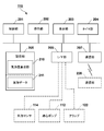
- FIG. 2 is a diagram illustrating an example of a functional configuration of the controller of the extracorporeal circulation apparatus.
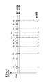
- FIG. 3 is a diagram illustrating an example of an output signal of the bubble sensor.
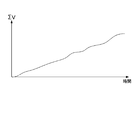
- FIG. 4 is a diagram showing the change over time of the cumulative value of the volume of bubbles.
- FIG. 5 is a flowchart showing the flow of the bubble amount calculation process in the controller.
- FIG. 6 is a diagram for explaining processing for extracting bubbles from bubble candidates detected by the second reference value.
- FIG. 1 is a diagram illustrating an example of the overall configuration of an extracorporeal circulation device 100 according to an embodiment of the present invention.
- the extracorporeal circulation device 100 is called PCPS (percutaneous cardiopulmonary support) and performs cardiopulmonary assist operations (extracorporeal circulation operation, priming operation).
- the extracorporeal circulation apparatus 100 has a blood extracorporeal circuit (hereinafter referred to as a circulation circuit) indicated by an arrow in the figure.
- a circulation circuit blood extracorporeal circuit
- an extracorporeal circulation operation is performed for circulating the blood of the subject 130 extracorporeally using this circulation circuit.
- the priming operation refers to an operation of removing bubbles in the circuit by circulating the priming solution in the circulation circuit in a state where the circulation circuit is sufficiently filled with the priming solution (for example, physiological saline).
- the priming solution for example, physiological saline
- the extracorporeal circulation device 100 includes a controller 110 that functions as a control device, a drive motor 111, a centrifugal pump 112, an oxygenator 113, an oxygen supply source 117, a catheter (venous side) 119, and a catheter (arterial side) 120.
- the catheter (arterial side) 120 pumps blood toward the body of the subject 130, and the catheter (venous side) 119 performs blood removal from the body of the subject 130.
- the centrifugal pump 112 is also called a centrifugal artificial heart, drives a rotating body provided inside, applies pressure to the blood, and circulates the blood in the circulation circuit.
- the drive motor 111 gives a rotational driving force to the rotating body of the centrifugal pump 112.
- the artificial lung 113 performs blood circulation and blood gas exchange (oxygen addition, carbon dioxide removal, etc.).
- the oxygen supply source 117 is realized by, for example, an oxygen cylinder and supplies oxygen to be added to blood.
- the oxygen supplied from the oxygen supply source 117 is used at the time of gas exchange by the artificial lung 113.
- the bubble sensor 114 detects bubbles contained in blood flowing in the circulation circuit during the extracorporeal circulation operation by a predetermined detection method (ultrasonic wave, light, etc.).
- the blood filter 116 filters blood or removes bubbles in the blood.
- the flow sensor 115 includes, for example, a built-in ultrasonic transceiver, and detects the flow rate of the priming liquid or blood in the circulation circuit.
- the clamp 122 is a member for closing the tube so as to forcibly stop the blood supply toward the body of the subject 130 during the extracorporeal circulation operation.
- the clamp 122 is operated when an automatic control mode for automatically performing a closing operation is set when it is determined that an abnormality that immediately stops blood supply has occurred based on an output signal from the bubble sensor 114. It is possible.
- the branch line 118 switches the flow path of the circulation circuit. Specifically, during an extracorporeal circulation operation in which the blood of the subject 130 is circulated extracorporeally, a circulation circuit passing through the body of the subject 130 is constructed as shown in 1A of FIG. Circulate blood. During the priming operation, as shown in 1B of FIG. 1, the circuit of the circulation circuit to the inside of the body of the subject 130 is blocked by the branch line 118 (in other words, the circulation circuit that passes only the outside of the subject 130 (in other words, the subject A circulation circuit that does not pass through the body of the person 130 is constructed, and the circulation circuit is filled with the priming liquid (without passing through the body of the subject) to circulate the priming liquid.
- one or a plurality of bubble discharge ports for discharging bubbles are provided on the circulation circuit.
- the bubbles in the circulation circuit are circulated. It will be discharged from the bubble discharge port.
- the controller 110 comprehensively controls the extracorporeal circulation operation and the priming operation in the extracorporeal circulation device 100.
- the centrifugal motor 112 is driven by controlling the drive motor 111.
- the bubble sensor 114 is controlled to acquire an output signal from the bubble sensor 114, or the flow rate sensor 115 is controlled to acquire a flow rate value.
- the clamp 122 is closed.
- the controller 110 controls the execution of the priming operation.
- a circulation circuit that does not pass through the body of the subject 130 is constructed by the branch line 118 as shown in 1B of FIG.
- the priming liquid supply source 121 is connected to the branch line 118, and the priming liquid is supplied from the priming liquid supply source 121 into the circulation circuit.
- the circulation circuit is filled with the priming liquid.
- the centrifugal pump 112 is driven by the control of the controller 110, and the priming liquid circulates in the circulation circuit. Bubbles in the circulation circuit are discharged from the bubble discharge port or the like with this circulation.
- the bubble sensor 114 may detect whether or not there is a function of flowing in the circulation circuit during the priming operation.
- the user who confirms that the priming is completed switches the branch line 118 and constructs a circulation circuit that passes through the body of the subject 130 as shown in FIG. 1A. Thereby, the blood of the subject 130 is circulated extracorporeally.
- the controller 110 has, as its functional configuration, a control unit (computer) 201, an operation unit 202, a display unit 203, a timer unit 204, a storage unit (computer-readable recording medium) 205, and an I / F unit 206. And a communication unit 207.
- the control unit 201 includes, for example, a CPU (Central Processing Unit), a ROM (Read Only Memory), a RAM (Random Access Memory), and the like, and various programs for realizing the above-described cardiopulmonary assist operation are stored in the ROM. It is assumed that
- the operation unit 202 is realized by, for example, various buttons and inputs an instruction from a medical worker.
- the display unit 203 is realized by, for example, a display such as a monitor (including an output unit that outputs an alarm sound), and displays various types of information to the user. Note that a part or all of the operation unit 202 and the display unit 203 may be realized as a touch panel with an audio speaker, for example.
- the timer unit 204 measures various times.
- the storage unit 205 is realized by, for example, a ROM and a RAM, and is executed by the control unit 201 in the interlocking operation control mode. Based on the output signal from the bubble sensor 114 during the extracorporeal circulation operation, the storage unit 205 A program for functioning as the bubble amount calculation unit 210 for calculating the accumulated value is stored. The output signal output from the bubble sensor 114 during the extracorporeal circulation operation is stored as the bubble data 211. The details of the bubble amount calculation process realized by using the bubble data 211 acquired by the control unit 201 executing a program that functions as the bubble amount calculation unit 210 will be described later.
- the storage unit 205 may be mounted in the control unit 201.
- the I / F unit 206 exchanges various signals with an external device. Note that an output signal from the bubble sensor 114 or the like is taken into the controller 110 via the I / F unit 206. Further, the centrifugal pump 112, the clamp 122, and the like operate based on an instruction from the controller 110 via the I / F unit 206.
- the communication unit 207 communicates with the communication unit 220 attached to the medical staff.
- the communication between the communication unit 207 and the communication unit 220 may be short-range wireless communication such as Bluetooth (registered trademark) or wireless communication using a wireless LAN such as Wi-Fi.
- FIG. 3 is a diagram for explaining the output signal from the bubble sensor 114 and the bubble detection logic based on the output signal.
- the horizontal axis represents the elapsed time since the bubble sensor 114 started detecting the bubble.
- the vertical axis represents the output signal from the bubble sensor 114.
- the output signal from the bubble sensor 114 is constantly fluctuating, and the cause of the fluctuation is a decrease in the level of the output signal due to the passage of the bubble and the level of the output signal due to various noises. Including decline.
- the decrease in the level of the output signal due to the passage of the bubble is proportional to the volume of the bubble that passes through. In this case, when the bubbles break up and pass through as many small bubble groups, the level of the output signal is small, but the level is repeatedly lowered in a short time.
- the level reduction of the output signal due to various noises is relatively small and is similar to the level reduction that occurs when a large number of bubble groups pass, but it is characterized by a single occurrence.
- the extracorporeal circulation apparatus 100 at least two stages of detection levels of the bubble sensor output signal are provided, and when there is a level drop below the first reference value, it is immediately determined that the bubbles are bubbles. If there is a level drop below the second reference value that is not lower than the reference value but higher than the first reference value, whether or not there are more than a certain number of the level drop within a certain time By determining whether it is a large number of bubbles having a small volume or noise.
- the values (V 11 to V 14 ) corresponding to the volume of the bubble are calculated by calculating the area of the region where the output signal is lower than the predetermined threshold.
- the level decrease of the output signal shown in V n1 and V n2 is not so much lower than the first reference value, but is a level decrease lower than the second reference value, so it is determined as a bubble candidate.
- a similar drop in output signal level has not occurred. Normally, when a mixed bubble breaks up and a large number of bubbles are formed, it will pass continuously in a short period of time, causing a single drop in level that falls below the second reference value. It's hard to think. For this reason, it is determined that the level reduction of the output signals indicated by V n1 and V n2 is caused by noise.
- the level decrease of the output signal indicated by V 21 to V 26 is not so much lower than the first reference value as the level decrease of the output signal indicated by V n1 and V n2 but is a level below the second reference value. Since it is a drop, it is determined as a bubble candidate. Further, since any of V 21 to V 26 has the same output signal level drop before or after (or both before and after), it is finally determined as a bubble.
- values (V 21 to V 26 ) corresponding to the volume of the bubble are calculated by calculating the area of the region where the output signal is lower than the predetermined threshold.
- the bubbles mixed in the blood sent to the subject are singly divided into large-volume bubbles that adversely affect the subject and, as described above, are divided and the volume of each bubble is small.
- a bubble that adversely affects the subject when it flows continuously for a certain period of time that is, if a group of broken bubbles is returned to the state of one mass before division, the subject is adversely affected. Large volume bubbles).
- the former bubble can be dealt with by monitoring the drop in the level of the output signal of the bubble sensor 114.
- FIG. 4 is a diagram showing a time change of the accumulated value obtained by accumulating the calculation results when the value corresponding to the volume of the bubble is calculated in FIG.
- the horizontal axis indicates the elapsed time from the start of detection of bubbles by the bubble sensor 114
- the vertical axis indicates the cumulative value ⁇ V.
- movement can be considered as operation
- the clamp 122 may be closed to stop blood feeding, or only an alarm may be output.
- the clamp 122 may be closed or an alarm may be output.
- FIG. 5 is a flowchart showing the flow (information processing method) of the bubble amount calculation process by the bubble amount calculation unit 210.
- step S501 it is determined whether or not a first reference value for detecting a large volume bubble and a second reference value for detecting a small volume bubble group are set. . If it is determined in step S501 that the first reference value and the second reference value are not set, the process waits until the setting is completed.
- step S502 acquisition of bubble data and storage in the storage unit 205 are started by starting reception of an output signal from the bubble sensor 114.
- step S503 the acquired bubble data is monitored, and it is determined whether or not a level lower than the first reference value has occurred. If it is determined in step S503 that no level decrease below the first reference value has occurred, the process proceeds to step S506.
- step S503 determines whether a level drop below the first reference value has occurred. If it is determined in step S503 that a level drop below the first reference value has occurred, the process proceeds to step S504, where the volume of the bubble is calculated by calculating the area of the region lower than the predetermined threshold. The value corresponding to is calculated. In step S505, the value calculated in step S504 is added to the cumulative value ⁇ V.
- step S506 the acquired bubble data is monitored, and it is determined whether or not a level drop occurs that is above the first reference value but below the second reference value. If it is determined in step S506 that the level is lower than the first reference value but not lower than the second reference value, the process proceeds to step S511.
- step S506 determines whether a level drop below the first reference value has not occurred, but a level drop below the second reference value has occurred. If it is determined in step S506 that a level drop below the first reference value has not occurred, but a level drop below the second reference value has occurred, the process proceeds to step S507.
- step S507 the number of level drops (number of bubble candidates) including the level drop within a predetermined time (the level drop that is not lower than the first reference value but lower than the second reference value) is counted.
- step S508 it is determined whether the count result counted in step S507 is equal to or greater than a predetermined value. If it is determined that the count result is not equal to or greater than the predetermined value, the level reduction is not caused by bubbles. It progresses to step S511.
- step S508 determines whether the value is equal to or greater than the predetermined value. If it is determined in step S508 that the value is equal to or greater than the predetermined value, the process proceeds to step S509, and a value corresponding to the volume of each bubble is calculated for each level decrease included in the predetermined time.
- step S510 among the values corresponding to the volume of each bubble calculated in step S509, a value not yet added to the cumulative value ⁇ V is added.
- step S511 it is determined whether or not the extracorporeal circulation operation has been completed. If it is determined that the extracorporeal circulation operation has not been completed, the process proceeds to step S503, and the bubble data monitoring is continued.
- step S511 if it is determined in step S511 that the extracorporeal circulation operation has ended, the bubble amount calculation process is ended.
- FIG. 6 is a diagram for explaining in detail processing for determining whether or not a bubble is present in steps S507 and S508.
- the horizontal axis indicates the elapsed time since the bubble sensor 114 started detecting bubbles
- the vertical axis indicates the output signal of the bubble sensor 114.
- 601 to 608 indicate that a level drop (bubble candidate) has occurred that is not less than the first reference value but falls below the second reference value
- W 1 to W 5 indicate that the level drop has occurred. It shows a predetermined time when counting the number of existing objects.
- the level drop 601 when the level drop 601 occurs, the predetermined time W 1, other reduced level it is determined that the bubble candidate has not occurred. For this reason, the level drop 601 is determined not to be a bubble.
- the predetermined time W 2 if the level decrease 602 occurs, the predetermined time W 2, other levels drop 603 it is determined that the bubble candidate has occurred.
- the bubble candidate occurring within a predetermined time W 2 are the only two level drop 602, at this point, once it is determined that no bubble (here, for convenience of explanation, the predetermined time period If four or more bubble candidates are generated, it is determined that the bubble is present).
- the predetermined time W 3 other levels drop 602, 604, 605 it is determined that the bubble candidate has occurred. That is, since there are more than a predetermined number of bubble candidates, it is determined that the level decrease 603 is a level decrease caused by bubbles. Furthermore, other levels drop 602, 604, 605 included in a predetermined time W 3 is also determined to be level decreases due to air bubbles.
- the level decrease 604 is determined to be a level decrease caused by bubbles. Furthermore, other levels drop 605, 606, 607 included in a predetermined time W 4 is also determined to be level decreases due to air bubbles.
- the level decrease 608 occurs, the predetermined time W 5, another reduced level it is judged that the bubble candidate (to a lesser extent below the first reference value, decrease the level below the second reference value) Has not occurred. For this reason, the level drop 608 is determined not to be a bubble.
- the extracorporeal circulation device 100 when monitoring the output signal of the bubble sensor, the first reference value that is immediately determined as a bubble and a level higher than the first reference value.
- the second reference value for detecting a large number of bubbles having a small volume is provided.
- the number of bubble candidates within a predetermined time is counted, and the count result is not less than the predetermined value.
- the bubble candidate included in the predetermined time is determined to be a bubble.
- the two reference values of the first reference value and the second reference value are provided.
- the present invention is not limited to this, and the reference value of three or more steps may be provided. Good.
- the value corresponding to the volume of the bubble calculated when the bubble is determined is added to the cumulative value ⁇ V.
- the present invention is not limited to this.
- a value corresponding to the volume of the bubble calculated when the level is lowered below the first reference value and a value that corresponds to the calculated volume of the bubble is less than the first reference value but less than the second reference value.
- a value corresponding to the volume of the bubble calculated when it is determined as a bubble due to the occurrence of a level drop may be added separately.
- a predetermined threshold that is, a fixed value
- a bubble is detected. It is also possible to calculate an average value of output signals in a non-period of time and use the average value (that is, a variable value) as a threshold value.
Landscapes
- Health & Medical Sciences (AREA)
- Heart & Thoracic Surgery (AREA)
- Vascular Medicine (AREA)
- Biomedical Technology (AREA)
- Engineering & Computer Science (AREA)
- Anesthesiology (AREA)
- Cardiology (AREA)
- Hematology (AREA)
- Life Sciences & Earth Sciences (AREA)
- Animal Behavior & Ethology (AREA)
- General Health & Medical Sciences (AREA)
- Public Health (AREA)
- Veterinary Medicine (AREA)
- External Artificial Organs (AREA)
Abstract
循環装置において、体積の小さい気泡を精度よく検出できるようにする。本発明は、被検者の血液を循環回路を用いて体外で循環させる循環装置であって、気泡センサと、前記気泡センサより出力された信号のうち、第一基準値を下回るレベル低下が発生した場合に、気泡と判断する第1の判断手段と、前記気泡センサより出力された信号のうち、第二基準値を下回るレベル低下が発生した場合に、気泡候補と判定し、当該気泡候補が、所定時間内に所定個数以上存在していた場合に、当該所定時間内に存在する各気泡候補を、気泡と判断する第2の判断手段とを備えることを特徴とする。
Description
本発明は、循環装置における情報処理技術に関するものである。
一般に、体外循環や補助循環等を行う循環装置では、循環回路内に気泡センサを配し、被検者に送り出される血液内に気泡が混入していないか否かを監視している。また、所定の大きさの気泡が検出された場合にあっては、当該気泡により被検者に悪影響が及ぶのを回避すべく、クランプを閉塞動作させ、被検者への送血を停止するなどの処置を行っている。
しかしながら、被検者に悪影響を及ぼす気泡は、所定の大きさを有する気泡ばかりではなく、例えば、分裂することで小さな気泡に分かれ、細かい気泡群となって一定時間連続して流れるような場合にも、当該気泡群が被検者に悪影響を及ぼすといったことが考えられる。
特に、送血速度が速い場合には、混入した気泡が分裂して、多数の小さな気泡群となって流れることが多く、このような体積の小さい気泡についても検出できるようにするとともに、このような体積の小さい気泡を累積加算しておき、気泡の総量を監視する構成とすることが望ましい。
一方で、気泡センサは、通常、気泡の大きさに応じてレベル低下する信号を出力する構成となっており、体積の小さな気泡の場合、出力される信号のレベル低下も小さく、ノイズ等と区別することが困難な状況となっている。
このようなことから、循環装置においては、多数の小さな気泡群を、ノイズ等と区別して、検出できるようにすることが不可欠である。
本発明は上記課題に鑑みてなされたものであり、循環装置において、体積の小さい気泡を精度よく検出できるようにすることを目的とする。
上記の目的を達成するために、本発明に係る循環装置は以下のような構成を備える。即ち、
被検者の血液を循環回路を用いて体外で循環させる循環装置であって、
前記循環回路に配され、循環される血液に混入する各気泡の大きさに応じてレベル低下する信号を出力する検出手段と、
前記検出手段より出力された信号のうち、第一基準値を下回るレベル低下が発生した場合に、気泡と判断する第1の判断手段と、
前記検出手段より出力された信号のうち、第一基準値を下回っていないが、第一基準値よりレベルの高い第二基準値を下回るレベル低下が発生した場合に、気泡候補と判定したうえで、当該気泡候補が、所定時間内に所定個数以上存在していた場合に、当該所定時間内に存在する各気泡候補を、気泡と判断する第2の判断手段とを備えることを特徴とする。
被検者の血液を循環回路を用いて体外で循環させる循環装置であって、
前記循環回路に配され、循環される血液に混入する各気泡の大きさに応じてレベル低下する信号を出力する検出手段と、
前記検出手段より出力された信号のうち、第一基準値を下回るレベル低下が発生した場合に、気泡と判断する第1の判断手段と、
前記検出手段より出力された信号のうち、第一基準値を下回っていないが、第一基準値よりレベルの高い第二基準値を下回るレベル低下が発生した場合に、気泡候補と判定したうえで、当該気泡候補が、所定時間内に所定個数以上存在していた場合に、当該所定時間内に存在する各気泡候補を、気泡と判断する第2の判断手段とを備えることを特徴とする。
本発明によれば、循環装置において、体積の小さい気泡を精度よく検出することが可能となる。
本発明のその他の特徴及び利点は、添付図面を参照とした以下の説明により明らかになるであろう。なお、添付図面においては、同じ若しくは同様の構成には、同じ参照番号を付す。
添付図面は明細書に含まれ、その一部を構成し、本発明の実施の形態を示し、その記述と共に本発明の原理を説明するために用いられる。
図1は、本発明の一実施形態に係る体外循環装置の全体構成を示す図である。
図2は、体外循環装置のコントローラの機能構成の一例を示す図である。
図3は、気泡センサの出力信号の一例を示す図である。
図4は、気泡の体積の累積値の時間変化を示す図である。
図5は、コントローラにおける気泡量算出処理の流れを示すフローチャートである。
図6は、第二基準値により検出された気泡候補の中から、気泡を抽出する処理を説明するための図である。
以下、本発明の各実施形態について添付図面を参照しながら詳細に説明する。なお、以下に述べる実施の形態は、本発明の好適な具体例であるから、技術的に好ましい種々の限定が付されているが、本発明の範囲は、以下の説明において特に本発明を限定する旨の記載がない限り、これらの態様に限られるものではない。
[第1の実施形態]
<1.体外循環装置の全体構成>
はじめに本発明の一実施形態に係る体外循環装置の全体構成について説明する。図1の1Aは、本発明の一実施形態に係る体外循環装置100の全体構成の一例を示す図である。
<1.体外循環装置の全体構成>
はじめに本発明の一実施形態に係る体外循環装置の全体構成について説明する。図1の1Aは、本発明の一実施形態に係る体外循環装置100の全体構成の一例を示す図である。
体外循環装置100は、PCPS(percutaneous cardiopulmonary support)などと呼ばれ、心肺補助動作(体外循環動作、プライミング動作)を行う。体外循環装置100は、図中矢印で示す血液体外循環回路(以下、循環回路と呼ぶ)を有している。体外循環装置100では、プライミング動作を行った後に、この循環回路を用いて被検者130の血液を体外循環させる体外循環動作を行う。
なお、プライミング動作とは、プライミング液(例えば、生理食塩水)で循環回路を十分に満たした状態で、循環回路内でプライミング液を循環させ、当該回路内の気泡を除去する動作をいう。
体外循環装置100は、制御装置として機能するコントローラ110と、ドライブモータ111と、遠心ポンプ112と、人工肺113と、酸素供給源117と、カテーテル(静脈側)119と、カテーテル(動脈側)120と、気泡センサ114と、流量センサ115と、血液フィルタ116と、分岐ライン118と、クランプ122とを備える。なお、これら各構成の間は、柔軟性を有するチューブ等によって接続されており、当該チューブの内腔が血液またはプライミング液の流路を構成している。
カテーテル(動脈側)120は、被検者130の体内に向けて送血し、カテーテル(静脈側)119は、被検者130の体内から脱血を行う。
遠心ポンプ112は、遠心式人工心臓とも呼ばれ、内部に設けられた回転体を駆動させて血液に圧力を与え、循環回路内で血液を循環させる。ドライブモータ111は、遠心ポンプ112の回転体に回転駆動力を与える。
人工肺113は、血液の循環と血液のガス交換(酸素付加、二酸化炭素除去等)とを行う。酸素供給源117は、例えば、酸素ボンベ等で実現され、血液に付加する酸素を供給する。酸素供給源117から供給される酸素は、人工肺113によるガス交換時に使用される。
気泡センサ114は、体外循環動作時に循環回路内を流れる血液に含まれる気泡を所定の検出方法(超音波、光等)により検出する。血液フィルタ116は、血液をろ過したり、血液中の気泡を除去したりする。流量センサ115は、例えば、超音波の送受信器を内蔵して構成され、循環回路内のプライミング液あるいは血液の流量を検出する。
クランプ122は、体外循環動作時に、被検者130の体内に向けての送血を強制的に停止させるべく、チューブを閉塞させるための部材である。クランプ122は、気泡センサ114からの出力信号に基づいて、送血をただちに停止させる異常が発生したと判定した場合に、自動的に閉塞動作を行う自動制御モードが設定されている場合に動作させることが可能である。
分岐ライン118は、循環回路の流路を切り替える。具体的には、被検者130の血液を体外循環させる体外循環動作時には、図1の1Aに示すように、被検者130の体内を通る循環回路を構築し、被検者130の体外で血液を循環させる。プライミング動作時には、図1の1Bに示すように、分岐ライン118によって被検者130の体内への循環回路の経路を遮断して被検者130の体外のみを通る循環回路(言い換えれば、被検者130の体内を通らない循環回路)を構築し、プライミング液で循環回路内を満たして(被検者の体内を通らずに)プライミング液を循環させる。循環回路上には、気泡を排出するための1又は複数の気泡排出ポート(不図示)が設けられており、循環回路内でプライミング液を複数周循環させることにより、循環回路内の気泡が当該気泡排出ポートから排出されることとなる。
コントローラ110は、体外循環装置100における体外循環動作及びプライミング動作を統括制御する。コントローラ110においては、例えば、ドライブモータ111を制御して遠心ポンプ112を駆動させる。また、気泡センサ114を制御して気泡センサ114からの出力信号を取得したり、流量センサ115を制御して流量値を取得したりする。更に、自動制御モードにあっては、気泡センサ114からの出力信号に基づいて、送血を停止させる必要がある異常があると判定した場合には、クランプ122を閉塞動作させる。
次に、図1の1A及び1Bに示す体外循環装置100を用いて心肺補助動作(体外循環動作、プライミング動作)を行う際の処理の流れについて簡単に説明する。
心肺補助動作が開始されると、コントローラ110は、プライミング動作の実行を制御する。プライミング動作時には、図1の1Bに示すように、分岐ライン118によって被検者130の体内を通らない循環回路が構築される。また、このとき、プライミング液供給源121が分岐ライン118に接続され、当該プライミング液供給源121から循環回路内にプライミング液が供給される。これにより、循環回路内は、プライミング液で満たされることになる。
そして、コントローラ110の制御によって遠心ポンプ112が駆動し、プライミング液が循環回路内を循環する。循環回路内の気泡は、この循環とともに気泡排出ポート等から排出される。また、プライミング動作時に気泡センサ114によって当該循環回路内を流れる機能の有無を検出してもよい。
プライミングが完了したことを確認したユーザは、分岐ライン118を切り替え、図1の1Aに示すように、被検者130の体内を通る循環回路を構築する。これにより、被検者130の血液が体外循環される。
体外循環動作が始まると、カテーテル(静脈側)119から脱血されてくる血液が、遠心ポンプ112を経て人工肺113に入る。人工肺113では、上述した通り、ガス交換、すなわち、酸素付加や二酸化炭素除去等の処理が行われる。その後、血液フィルタ116等を経て、ろ過された血液が、カテーテル(動脈側)120から被検者130の体内に送血される。このカテーテル(静脈側)119~カテーテル(動脈側)120までの被検者130の血液の流れが連続的に行われる。なお、体外循環動作時にも気泡センサ114によって循環回路内の気泡の検出が行われ、検出結果に応じた処理(自動制御モードにおけるクランプの閉塞動作等)が実行される。
以上が、本実施形態に係る体外循環装置100の全体構成及び心肺補助動作の流れの一例についての説明である。なお、図1の1A及び1Bに示す体外循環装置100の構成は、あくまでも一例にすぎず、その構成は適宜変更されてもよい。
<2.コントローラの機能構成>
次に、図2を用いて、図1に示すコントローラ110の機能構成の一例について説明する。
次に、図2を用いて、図1に示すコントローラ110の機能構成の一例について説明する。
コントローラ110は、その機能構成として、制御部(コンピュータ)201と、操作部202と、表示部203と、タイマ部204と、記憶部(コンピュータ読取可能な記録媒体)205と、I/F部206と、通信部207とを備える。
制御部201は、例えば、CPU(Central Processing Unit)、ROM(Read Only Memory)及びRAM(Random Access Memory)等で構成され、ROMには、上述した心肺補助動作を実現するための各種プログラムが格納されているものとする。
操作部202は、例えば、各種ボタン等で実現され、医療従事者からの指示を入力する。表示部203は、例えば、モニタ等の表示器(警報を音声出力する出力部を含む)で実現され、各種情報をユーザに向けて表示する。なお、操作部202及び表示部203の一部又は全部は、例えば、音声スピーカ付のタッチパネルとして実現されてもよい。
タイマ部204は、各種時間の計時を行う。記憶部205は、例えば、ROM及びRAM等で実現されており、連動動作制御モードにおいて、制御部201において実行され、体外循環動作中の気泡センサ114からの出力信号に基づいて、気泡の体積の累積値を算出する気泡量算出部210として機能するためのプログラムを格納している。また、体外循環動作中に気泡センサ114から出力された出力信号が、気泡データ211として格納される。なお、気泡量算出部210として機能するプログラムが制御部201により実行されることにより取得される気泡データ211を用いて実現される気泡量算出処理の詳細は後述するものとする。また、記憶部205は制御部201の中に搭載されていてもよい。
I/F部206は、外部装置との間で各種信号の授受を行う。なお、気泡センサ114等からの出力信号は、I/F部206を介してコントローラ110に取り込まれる。また、遠心ポンプ112やクランプ122等は、I/F部206を介してコントローラ110からの指示に基づいて動作する。
通信部207は、医療従事者に装着された通信部220との間で通信を行う。なお、通信部207と通信部220との間の通信は、Bluetooth(登録商標)等の近距離無線通信であっても、Wi-Fi等の無線LANによる無線通信であってもよい。
以上が、コントローラ110についての機能構成の一例についての説明である。なお、図2に示す機能構成はあくまでも一例であり、新たな構成が追加されてもよいし、また、不要な構成が適宜省略されてもよい。
<3.気泡センサからの出力信号の説明と、気泡の検出ロジック>
次に、気泡センサ114からの出力信号と、当該出力信号に基づく気泡の検出ロジックについて説明する。図3は、気泡センサ114からの出力信号と、当該出力信号に基づく気泡の検出ロジックを説明するための図であり、横軸は、気泡センサ114による気泡の検出が開始されてからの経過時間を示しており、縦軸は、気泡センサ114からの出力信号を示している。
次に、気泡センサ114からの出力信号と、当該出力信号に基づく気泡の検出ロジックについて説明する。図3は、気泡センサ114からの出力信号と、当該出力信号に基づく気泡の検出ロジックを説明するための図であり、横軸は、気泡センサ114による気泡の検出が開始されてからの経過時間を示しており、縦軸は、気泡センサ114からの出力信号を示している。
図3に示すように、気泡センサ114からの出力信号は常時変動しており、その変動の原因には、気泡が通過したことに伴う出力信号のレベル低下と、各種ノイズに伴う出力信号のレベル低下とが含まれる。このうち、気泡が通過したことに伴う出力信号のレベル低下は、通過する気泡の体積に比例しており、比較的大きい気泡が通過した場合には、出力信号のレベル低下も大きい一方で、混入した際に気泡が分裂し、多数の小さな気泡群となって通過した場合には、出力信号のレベル低下は小さいが、短時間の間に繰り返しレベル低下が生じるといった特徴がある。
一方、各種ノイズに伴う出力信号のレベル低下は、比較的小さく、多数の気泡群が通過した場合に生じるレベル低下と同程度であるが、単発的に発生するといった特徴がある。
このようなことから、気泡センサ114からの出力信号に基づいて、気泡を精度よく検出するにあたっては、出力信号のレベル低下が大きい場合には、ただちに気泡と判断する一方で、出力信号のレベル低下が小さい場合には、連続的に発生しているか否かを判定し、連続的に発生していれば体積の小さい多数の気泡群であると判断し、連続的に発生していなければ、単発のノイズであると判断することが有効であるといえる。
このため、本実施形態に係る体外循環装置100では、気泡センサ出力信号の検出レベルを少なくとも2段階設け、第一基準値を下回るレベル低下があった場合には、ただちに気泡と判断し、第一基準値を下回るほどではないが、第一基準値よりもレベルの高い第二基準値を下回るレベル低下があった場合には、当該レベル低下が一定時間内に所定個数以上存在しているか否かを判定することにより、体積の小さな多数の気泡群であるのかノイズであるのかを判断する構成とした。
図3の例では、V11~V14に示す出力信号のレベル低下は、第一基準値を下回るレベル低下であるため、気泡と判断される。この場合、出力信号が所定の閾値よりも低い領域の面積を算出することにより、気泡の体積に対応する値(V11~V14)を算出する。
一方、Vn1、Vn2に示す出力信号のレベル低下は、第一基準値を下回るほどではないが、第二基準値を下回るレベル低下であるため、気泡候補と判定されるが、前後に、同様の出力信号のレベル低下が発生していない。通常、混入した気泡が分裂し、多数の気泡群が形成された場合には、短時間の間に連続して通過することとなるため、第二基準値を下回るレベル低下が、単発的に発生することは考えにくい。このため、Vn1、Vn2に示す出力信号のレベル低下は、ノイズによるものと判断する。
一方、V21~V26に示す出力信号のレベル低下は、Vn1、Vn2に示す出力信号のレベル低下と同様に、第一基準値を下回るほどではないが、第二基準値を下回るレベル低下であるため、気泡候補と判定される。更に、V21~V26のいずれも、前または後に(あるいは前後両方)に、同様の出力信号のレベル低下が発生しているため、最終的に、気泡と判断される。
この場合、出力信号が所定の閾値よりも低い領域の面積を算出することにより、気泡の体積に対応する値(V21~V26)を算出する。
<4.気泡の体積の累積値の時間変化>
次に、気泡と判断され、気泡の体積に対応する値(V11~V14、V21~V26)の算出結果の処理について説明する。
次に、気泡と判断され、気泡の体積に対応する値(V11~V14、V21~V26)の算出結果の処理について説明する。
一般に、被検者に送り出される血液内に混入する気泡には、単独で、被検者に悪影響を及ぼす体積の大きい気泡と、上述したように、分裂され、1つ1つの気泡の体積は小さいが、一定時間連続して流れた場合に、被検者に悪影響を及ぼす気泡(つまり、分裂した気泡群を、仮に分裂前の1つのかたまりの状態に戻したとした場合に、被検者に悪影響を及ぼす体積の大きい気泡)とがある。
このうち、前者の気泡については、気泡センサ114の出力信号のレベル低下を監視しておくことで、対応することができる。一方、後者の気泡については、気泡の体積の累積値を算出し、当該累積値の時間変化を監視しておくことが重要となってくる。
図4は、図3において、気泡と判断され、気泡の体積に対応する値が算出された場合において、当該算出結果を累積加算することにより得られる累積値の時間変化を示す図である。
図4において、横軸は、気泡センサ114による気泡の検出が開始されてからの経過時間を示しており、縦軸は、累積値ΣVを示している。気泡センサ114による気泡の検出が開始された時点では、累積値ΣVにはゼロが入力されているが、時間T1(図3)が経過した際に、V11が加算され、時間T2(図3)が経過した際に、V12が加算される。以下、同様に、時間T3~T10が経過するごとに、V21~V26、V13、V14が加算される。
これにより、図4に示すように、累積値ΣVは、時間の経過とともに徐々に増加していくことなる。
なお、図4に示す累積値ΣVの時間変化に対する、体外循環装置100の動作としては種々の動作が考えられる。例えば、累積値ΣVが所定の値に到達した場合に、クランプ122を閉塞動作させ、送血を停止させるように構成してもよいし、警報のみを出力する構成としてもよい。
また、累積値ΣVの所定時間あたりの増加度が所定の値に到達した場合に、クランプ122を閉塞動作させたり、警報を出力したりする構成としてもよい。
<5.気泡量算出処理の流れ>
次に、気泡量算出部210による気泡量算出処理の流れについて図5及び図6を用いて説明する。図5は、気泡量算出部210による気泡量算出処理の流れ(情報処理方法)を示すフローチャートである。
次に、気泡量算出部210による気泡量算出処理の流れについて図5及び図6を用いて説明する。図5は、気泡量算出部210による気泡量算出処理の流れ(情報処理方法)を示すフローチャートである。
図5に示すように、ステップS501では、体積の大きい気泡を検出するための第一基準値と、体積の小さい気泡群を検出するための第二基準値とが設定されたか否かを判定する。ステップS501において、第一基準値及び第二基準値が設定されていないと判定された場合には、設定が完了するまで待機する。
一方、第一基準値及び第二基準値の設定が完了したと判定された場合には、ステップS502に進む。ステップS502では、気泡センサ114からの出力信号の受信を開始することで、気泡データの取得及び記憶部205への格納を開始する。
ステップS503では、取得した気泡データを監視し、第一基準値を下回るレベル低下が発生しているか否かを判定する。ステップS503において、第一基準値を下回るレベル低下が発生していないと判定された場合には、ステップS506に進む。
一方、ステップS503において、第一基準値を下回るレベル低下が発生していると判定された場合には、ステップS504に進み、所定の閾値よりも低い領域の面積を算出することにより、気泡の体積に対応する値を算出する。更に、ステップS505では、ステップS504において算出された値を、累積値ΣVに加算する。
ステップS506では、取得した気泡データを監視し、第一基準値は上回っているが第二基準値を下回るレベル低下が発生しているか否かを判定する。ステップS506において、第一基準値は上回っているが第二基準値を下回るレベル低下が発生していないと判定された場合には、ステップS511に進む。
一方、ステップS506において、第一基準値を下回るレベル低下は発生していないが、第二基準値を下回るレベル低下は発生していると判定された場合には、ステップS507に進む。
ステップS507では、当該レベル低下を含む、所定時間内におけるレベル低下(第一基準値を下回るほどではないが、第二基準値を下回るレベル低下)の個数(気泡候補の個数)をカウントする。
ステップS508では、ステップS507においてカウントされたカウント結果が、所定値以上であるか否かを判定し、所定値以上でないと判定された場合には、当該レベル低下が、気泡に起因するものではないと判断し、ステップS511に進む。
一方、ステップS508において、所定値以上であると判定された場合には、ステップS509に進み、所定時間内に含まれる各レベル低下について、各気泡の体積に対応する値を算出する。
更に、ステップS510では、ステップS509において算出された、各気泡の体積に対応する値のうち、累積値ΣVに未だ加算されていない値を加算する。
ステップS511では、体外循環動作が終了したか否かを判定し、終了していないと判定された場合には、ステップS503に進み、気泡データの監視を継続する。
一方、ステップS511において、体外循環動作が終了したと判定された場合には、気泡量算出処理を終了する。
図6は、ステップS507及びステップS508において、気泡か否かを判断する処理を詳細に説明するための図である。図6において、横軸は、気泡センサ114による気泡の検出が開始されてからの経過時間を示しており、縦軸は、気泡センサ114の出力信号を示している。また、601~608は、第一基準値を下回るほどではないが、第二基準値を下回るレベル低下(気泡候補)が発生したことを示しており、W1~W5は、当該レベル低下が存在する個数をカウントする際の所定時間を示している。
図6に示すように、レベル低下601が発生した場合に、所定時間W1内には、気泡候補と判定された他のレベル低下は発生していない。このため、レベル低下601は、気泡ではないと判断される。
一方、レベル低下602が発生した場合に、所定時間W2内には、気泡候補と判定された他のレベル低下603が発生している。しかしながら、所定時間W2内において発生している気泡候補は、2つのみであるため、レベル低下602は、この時点では、一旦、気泡でないと判定される(ここでは、説明の便宜上、所定時間内に気泡候補が4つ以上発生していた場合に、気泡と判断することとする)。
一方、レベル低下603が発生した場合に、所定時間W3内には、気泡候補と判定された他のレベル低下602、604、605が発生している。つまり、所定個数以上の気泡候補が存在しているため、レベル低下603は、気泡に起因するレベル低下であると判断される。更に、所定時間W3内に含まれる他のレベル低下602、604、605も、気泡に起因するレベル低下であると判断される。
同様に、レベル低下604が発生した場合にも、所定時間W4内には、気泡候補と判定された他のレベル低下605、606、607が発生しており、所定個数以上であることから、レベル低下604は、気泡に起因するレベル低下であると判断される。更に、所定時間W4内に含まれる他のレベル低下605、606、607も、気泡に起因するレベル低下であると判断される。
一方、レベル低下608が発生した場合に、所定時間W5内には、気泡候補と判定された他のレベル低下(第一基準値を下回るほどではないが、第二基準値を下回るレベル低下)は発生していない。このため、レベル低下608は、気泡でないと判断される。
以上の説明から明らかなように、本実施形態に係る体外循環装置100では、気泡センサの出力信号を監視するにあたり、ただちに気泡と判断する第一基準値と、第一基準値よりも高いレベルであって、体積の小さい多数の気泡群を検出する第二基準値とを設ける構成とした。
更に、第二基準値において気泡候補として検出されたレベル低下のうち、ノイズに起因するレベル低下を排除するために、所定時間内における気泡候補の個数をカウントし、カウント結果が、所定値以上であった場合に、当該所定時間内に含まれる気泡候補を、気泡と判断する構成とした。
このように、1つのかたまりの気泡が分裂し、体積の小さい多数の気泡群となって流れた場合の、気泡センサの出力信号の特性を考慮に入れることにより、気泡とノイズとを適確に区別することが可能となった。
この結果、体積の小さい気泡を精度よく検出することが可能となった。
[第2の実施形態]
上記第1の実施形態では、第一基準値と第二基準値の2段階の基準値を設ける構成としたが、本発明はこれに限定されず、3段階以上の基準値を設ける構成としてもよい。
上記第1の実施形態では、第一基準値と第二基準値の2段階の基準値を設ける構成としたが、本発明はこれに限定されず、3段階以上の基準値を設ける構成としてもよい。
また、上記第1の実施形態では、気泡と判断された場合に算出された、気泡の体積に対応する値を全て累積値ΣVに加算する構成としたが、本発明はこれに限定されない。例えば、第一基準値を下回るレベル低下が発生することで気泡と判断された場合に算出された気泡の体積に対応する値と、第一基準値を下回るほどではないが第二基準値を下回るレベル低下が発生することで気泡と判断された場合に算出された気泡の体積に対応する値とを、それぞれ、別々に加算するように構成してもよい。
また、上記第1の実施形態では、気泡の体積に対応する値を算出するにあたり、所定の閾値(つまり固定値)を用いる構成としたが、本発明はこれに限定されず、気泡が検出されていない時間帯における出力信号の平均値を算出し、当該平均値(つまり可変値)を閾値として用いるようにしてもよい。
[その他の実施形態]
本発明は上記実施の形態に制限されるものではなく、本発明の精神及び範囲から離脱することなく、様々な変更及び変形が可能である。従って、本発明の範囲を公にするために、以下の請求項を添付する。
本発明は上記実施の形態に制限されるものではなく、本発明の精神及び範囲から離脱することなく、様々な変更及び変形が可能である。従って、本発明の範囲を公にするために、以下の請求項を添付する。
Claims (8)
- 被検者の血液を循環回路を用いて体外で循環させる循環装置であって、
前記循環回路に配され、循環される血液に混入する各気泡の大きさに応じてレベル低下する信号を出力する検出手段と、
前記検出手段より出力された信号のうち、第一基準値を下回るレベル低下が発生した場合に、気泡と判断する第1の判断手段と、
前記検出手段より出力された信号のうち、第一基準値を下回っていないが、第一基準値よりレベルの高い第二基準値を下回るレベル低下が発生した場合に、気泡候補と判定したうえで、当該気泡候補が、所定時間内に所定個数以上、存在していた場合に、当該所定時間内に存在する各気泡候補を、気泡と判断する第2の判断手段と
を備えることを特徴とする循環装置。 - 前記第1及び/または第2の判断手段において気泡と判断されたレベル低下についてそれぞれ算出された、各気泡の体積に対応する値を累積することで、累積値を算出する算出手段を更に備えることを特徴とする請求項1に記載の循環装置。
- 前記算出手段は、前記検出手段により出力された信号のうち、前記気泡と判断されたレベル低下が発生した際の、該信号の所定の閾値よりも低い領域の面積を算出することにより、前記気泡の体積に対応する値を算出することを特徴とする請求項2に記載の循環装置。
- 前記算出手段により算出された累積値が、所定の値となった場合に、前記血液の循環を停止させることを特徴とする請求項3に記載の循環装置。
- 被検者の血液を循環回路を用いて体外で循環させる循環装置を制御する制御装置であって、
前記循環回路に配され、循環される血液に混入する気泡の大きさに応じて、出力される信号がレベル低下する気泡センサより、該信号を受信する受信手段と、
前記受信手段により受信された信号のうち、第一基準値を下回るレベル低下が発生した場合に、気泡と判断する第1の判断手段と、
前記受信手段により受信された信号のうち、第一基準値を下回っていないが、第一基準値よりレベルの高い第二基準値を下回るレベル低下が発生した場合に、気泡候補と判定したうえで、当該気泡候補が、所定時間内に所定個数以上存在していた場合に、当該所定時間内に存在する各気泡候補を、気泡と判断する第2の判断手段と
を備えることを特徴とする制御装置。 - 被検者の血液を循環回路を用いて体外で循環させる循環装置を制御する制御装置における情報処理方法であって、
前記循環回路に配され、循環される血液に混入する気泡の大きさに応じて、出力される信号がレベル低下する気泡センサより、該信号を受信する受信工程と、
前記受信工程において受信された信号のうち、第一基準値を下回るレベル低下が発生した場合に、気泡と判断する第1の判断工程と、
前記受信工程において受信された信号のうち、第一基準値を下回っていないが、第一基準値よりレベルの高い第二基準値を下回るレベル低下が発生した場合に、気泡候補と判定したうえで、当該気泡候補が、所定時間内に所定個数以上存在していた場合に、当該所定時間内に存在する各気泡候補を、気泡と判断する第2の判断工程と
を備えることを特徴とする情報処理方法。 - コンピュータを、請求項5に記載の制御装置の各手段として機能させるためのプログラム。
- コンピュータを、請求項5に記載の制御装置の各手段として機能させるためのプログラムを格納したコンピュータ読取可能の記録媒体。
Priority Applications (1)
| Application Number | Priority Date | Filing Date | Title |
|---|---|---|---|
| PCT/JP2013/001063 WO2014128764A1 (ja) | 2013-02-25 | 2013-02-25 | 循環装置、制御装置及び情報処理方法 |
Applications Claiming Priority (1)
| Application Number | Priority Date | Filing Date | Title |
|---|---|---|---|
| PCT/JP2013/001063 WO2014128764A1 (ja) | 2013-02-25 | 2013-02-25 | 循環装置、制御装置及び情報処理方法 |
Publications (1)
| Publication Number | Publication Date |
|---|---|
| WO2014128764A1 true WO2014128764A1 (ja) | 2014-08-28 |
Family
ID=51390610
Family Applications (1)
| Application Number | Title | Priority Date | Filing Date |
|---|---|---|---|
| PCT/JP2013/001063 Ceased WO2014128764A1 (ja) | 2013-02-25 | 2013-02-25 | 循環装置、制御装置及び情報処理方法 |
Country Status (1)
| Country | Link |
|---|---|
| WO (1) | WO2014128764A1 (ja) |
Citations (4)
| Publication number | Priority date | Publication date | Assignee | Title |
|---|---|---|---|---|
| JP2002131288A (ja) * | 2000-10-24 | 2002-05-09 | Toray Ind Inc | 気泡検出クランパおよび人工透析装置 |
| JP2005046404A (ja) * | 2003-07-30 | 2005-02-24 | Jms Co Ltd | 気泡検出システム、該気泡検出システムを備えた血液透析回路 |
| JP2005185832A (ja) * | 2003-12-03 | 2005-07-14 | Ethicon Endo Surgery Inc | 気泡監視投薬アセンブリ、医療システム、および気泡監視方法 |
| JP2012513285A (ja) * | 2008-12-22 | 2012-06-14 | カリディアンビーシーティー、インコーポレーテッド | 気泡検出器を備えた血液処理装置 |
-
2013
- 2013-02-25 WO PCT/JP2013/001063 patent/WO2014128764A1/ja not_active Ceased
Patent Citations (4)
| Publication number | Priority date | Publication date | Assignee | Title |
|---|---|---|---|---|
| JP2002131288A (ja) * | 2000-10-24 | 2002-05-09 | Toray Ind Inc | 気泡検出クランパおよび人工透析装置 |
| JP2005046404A (ja) * | 2003-07-30 | 2005-02-24 | Jms Co Ltd | 気泡検出システム、該気泡検出システムを備えた血液透析回路 |
| JP2005185832A (ja) * | 2003-12-03 | 2005-07-14 | Ethicon Endo Surgery Inc | 気泡監視投薬アセンブリ、医療システム、および気泡監視方法 |
| JP2012513285A (ja) * | 2008-12-22 | 2012-06-14 | カリディアンビーシーティー、インコーポレーテッド | 気泡検出器を備えた血液処理装置 |
Similar Documents
| Publication | Publication Date | Title |
|---|---|---|
| US10391224B2 (en) | Pressure sensing extracorporeal circulation device | |
| JP6005844B2 (ja) | 循環装置及びその制御方法 | |
| JP6573878B2 (ja) | 医療用インペラポンプを監視する方法 | |
| JP5997368B2 (ja) | 循環装置及びその制御方法 | |
| CN104837515B (zh) | 用于监测体外血液回路以检测气泡的装置和方法 | |
| CA3230625A1 (en) | System and method for ventricular assistance support during extracorporeal membrane oxygenation | |
| WO2019181610A1 (ja) | 体外循環装置および評価ユニット | |
| JP5851616B2 (ja) | 制御装置、循環装置及び制御方法 | |
| JP6296815B2 (ja) | 体外循環装置及び体外循環装置の制御方法 | |
| JP4433717B2 (ja) | 気泡検出システム、該気泡検出システムを備えた血液透析回路 | |
| WO2016035714A1 (ja) | 体外循環装置及びその制御方法 | |
| JP6170603B2 (ja) | 循環装置及びその制御方法 | |
| JP5947450B2 (ja) | 循環装置、制御装置及び情報処理方法 | |
| WO2014128763A1 (ja) | 循環装置、制御装置及び情報処理方法 | |
| JP5918364B2 (ja) | 体外循環装置及びプライミング方法 | |
| WO2015141622A1 (ja) | 警報装置、体外循環装置及び警報装置の制御方法 | |
| JP5852248B2 (ja) | 体外循環装置、制御装置及びその制御方法 | |
| WO2014162359A1 (ja) | 体外循環装置、体外循環装置の制御方法及び記憶媒体 | |
| WO2014162358A1 (ja) | 体外循環装置 | |
| JP6138643B2 (ja) | 体外循環装置 |
Legal Events
| Date | Code | Title | Description |
|---|---|---|---|
| 121 | Ep: the epo has been informed by wipo that ep was designated in this application |
Ref document number: 13875578 Country of ref document: EP Kind code of ref document: A1 |
|
| NENP | Non-entry into the national phase |
Ref country code: DE |
|
| 122 | Ep: pct application non-entry in european phase |
Ref document number: 13875578 Country of ref document: EP Kind code of ref document: A1 |
|
| NENP | Non-entry into the national phase |
Ref country code: JP |