WO2014125680A1 - パケット通信方法及び装置 - Google Patents
パケット通信方法及び装置 Download PDFInfo
- Publication number
- WO2014125680A1 WO2014125680A1 PCT/JP2013/078895 JP2013078895W WO2014125680A1 WO 2014125680 A1 WO2014125680 A1 WO 2014125680A1 JP 2013078895 W JP2013078895 W JP 2013078895W WO 2014125680 A1 WO2014125680 A1 WO 2014125680A1
- Authority
- WO
- WIPO (PCT)
- Prior art keywords
- packets
- packet
- acknowledgment
- discard rate
- communication device
- Prior art date
- Legal status (The legal status is an assumption and is not a legal conclusion. Google has not performed a legal analysis and makes no representation as to the accuracy of the status listed.)
- Ceased
Links
Images


Classifications
-
- H—ELECTRICITY
- H04—ELECTRIC COMMUNICATION TECHNIQUE
- H04L—TRANSMISSION OF DIGITAL INFORMATION, e.g. TELEGRAPHIC COMMUNICATION
- H04L43/00—Arrangements for monitoring or testing data switching networks
- H04L43/08—Monitoring or testing based on specific metrics, e.g. QoS, energy consumption or environmental parameters
- H04L43/0823—Errors, e.g. transmission errors
- H04L43/0829—Packet loss
-
- H—ELECTRICITY
- H04—ELECTRIC COMMUNICATION TECHNIQUE
- H04L—TRANSMISSION OF DIGITAL INFORMATION, e.g. TELEGRAPHIC COMMUNICATION
- H04L1/00—Arrangements for detecting or preventing errors in the information received
- H04L1/12—Arrangements for detecting or preventing errors in the information received by using return channel
- H04L1/16—Arrangements for detecting or preventing errors in the information received by using return channel in which the return channel carries supervisory signals, e.g. repetition request signals
- H04L1/18—Automatic repetition systems, e.g. Van Duuren systems
- H04L1/1867—Arrangements specially adapted for the transmitter end
- H04L1/1874—Buffer management
- H04L1/1877—Buffer management for semi-reliable protocols, e.g. for less sensitive applications like streaming video
-
- H—ELECTRICITY
- H04—ELECTRIC COMMUNICATION TECHNIQUE
- H04L—TRANSMISSION OF DIGITAL INFORMATION, e.g. TELEGRAPHIC COMMUNICATION
- H04L1/00—Arrangements for detecting or preventing errors in the information received
- H04L1/20—Arrangements for detecting or preventing errors in the information received using signal quality detector
- H04L1/203—Details of error rate determination, e.g. BER, FER or WER
-
- H—ELECTRICITY
- H04—ELECTRIC COMMUNICATION TECHNIQUE
- H04L—TRANSMISSION OF DIGITAL INFORMATION, e.g. TELEGRAPHIC COMMUNICATION
- H04L5/00—Arrangements affording multiple use of the transmission path
- H04L5/003—Arrangements for allocating sub-channels of the transmission path
- H04L5/0053—Allocation of signalling, i.e. of overhead other than pilot signals
- H04L5/0055—Physical resource allocation for ACK/NACK
-
- H—ELECTRICITY
- H04—ELECTRIC COMMUNICATION TECHNIQUE
- H04W—WIRELESS COMMUNICATION NETWORKS
- H04W24/00—Supervisory, monitoring or testing arrangements
- H04W24/08—Testing, supervising or monitoring using real traffic
Definitions
- the present invention relates to a packet communication method and apparatus.
- cloud computing commonly known as the cloud
- users use computer resources of an external data center rather than a base where users exist. Since data is also placed in the data center, data is frequently exchanged between the user's base and the data center.
- the location of data centers is spread all over the world and is not always in the same country. For example, overseas data centers may have lower data center usage fees, and overseas data centers are also actively used.
- RTT Round Trip TimeRT
- Patent Document 1 realizes high-speed communication by controlling the transmission data amount regardless of the RTT.
- the amount of transmission data is controlled by observing changes in the packet discard rate.
- information such as NACK (Negative ACKnowledgement) transmitted / received between a transmission device and a reception device corresponding to this method is used to measure the packet discard rate.
- NACK Negative ACKnowledgement
- a packet for quality measurement is used as a method for measuring the packet discard rate.
- the reception probe adds a packet reception counter to the quality measurement packet received from the transmission probe and returns the packet to the transmission probe. Subsequently, after the transmission probe extracts the number of received packets from the received quality measurement packet and receives all the quality measurement packets, the difference between the packet transmission counter and the packet reception counter, and the extracted packet reception counter.
- the packet loss rate (packet discard rate) is calculated by obtaining the difference between the packet return counter and the packet reply counter.
- Patent Document 1 high-speed communication is realized by controlling the amount of transmission data by observing changes in the packet discard rate.
- both the communication terminal on the transmission side and the reception side need to support the communication method of Patent Document 1, such as using NACK for data reception confirmation.
- communication with a terminal using a general communication method such as Non-Patent Document 1 or Non-Patent Document 2 also occurs. Therefore, in communication with a terminal that does not support the communication method of Patent Document 1, in order to control the amount of transmission data based on the change of the packet discard rate, information obtained by a general communication method is used. It is necessary to measure the packet discard rate.
- an object of the present invention is to obtain a packet discard rate using only information included in a general communication protocol.
- the communication device includes a transmission unit that transmits a packet to another communication device via a network, and information on a selective confirmation response and information on a confirmation response for the packet transmitted from the transmission unit from the other communication device.
- a reception unit that receives an acknowledgment packet via a network, a packet count unit that obtains the number of transmission packets that is the number of packets transmitted from the transmission unit, the number of transmission packets, information on the acknowledgment, and selective acknowledgment
- a discard rate measuring unit for obtaining a discard rate of packets transmitted from the transmitting unit during a predetermined period.
- the packet count unit obtains the number of retransmission request packets that are the number of packets requested for retransmission among the packets transmitted from the transmission unit based on the information of the confirmation response and the selective confirmation response, and measures the discard rate.
- the unit obtains the discard rate based on the number of transmission packets and the number of retransmission request packets.
- the packet count unit includes the number of confirmation response packets received by the reception unit and the information on the selective confirmation response immediately before the confirmation response packet among the confirmation response packets received by the reception unit.
- the number of duplicate packets which is the number of acknowledgment packets matching the selective acknowledgment information of the received acknowledgment packet, is obtained, and the discard rate measurement unit determines the number of transmitted packets, the number of acknowledgment packets, and the number of duplicate packets. Based on this, the discard rate is obtained.
- the discard rate measuring unit changes the method for obtaining the discard rate according to the high discard rate.
- a packet discard rate measuring method for measuring a discard rate of a packet transmitted from a communication device to a network.
- the packet discard rate measurement method obtains the number of transmitted packets, which is the number of packets sent from the communication device to the network, and the number of transmitted packets and the confirmation response included in the confirmation response packet received by the communication device via the network; Based on the information on the selective confirmation response, a discard rate of packets transmitted from the communication apparatus to the network in a predetermined period is obtained.
- the number of retransmission request packets which is the number of packets requested to be retransmitted among the packets sent to the network, is determined based on the information of the confirmation response and the selective confirmation response. Based on the above, the discard rate is obtained.
- the number of acknowledgment packets that are the number of acknowledgment packets received by the communication device, and the acknowledgment that the selective acknowledgment information of the acknowledgment packets received by the communication device is received immediately before the acknowledgment packet.
- the number of duplicate packets which is the number of acknowledgment packets that match the packet selective acknowledgment information, is obtained, and the discard rate is obtained based on the number of transmitted packets, the number of acknowledgment packets, and the number of duplicate packets.
- the method for determining the discard rate is changed according to the high discard rate.
- an accurate packet discard rate can be measured even when a general communication protocol is used.
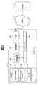
- FIG. 2 is a system configuration diagram of the first embodiment of the present invention and a hardware configuration diagram of the transmission terminal 1.
- the transmitting terminal 1 stores at least a network interface (hereinafter referred to as NIF) 10, a main memory 25 that temporarily stores programs and data, and reads and writes data, and stores programs and data for a long period of time and loads them into the main memory 25 as necessary.
- NIF network interface
- a processing device 27 that executes a program on the main memory 25, processes data on the main memory 25 and writes the result to the main memory 25, and a system bus 28 that interconnects them and transfers data Become.
- the main memory 25 stores the unique TCP function 3, application program 18, application data 19, and the like.
- the application program 18 is executed by the processing device 27 using the application data 19 and controls transmission data using the unique TCP function 3.
- the unique TCP function 3 sends the transmission data to the NIF 10, and the NIF 10 transmits the transmission data to the WAN 4.
- FIG. 2 shows an example in which the unique TCP function 3 is entirely configured by software, a part or all of the unique TCP function 3 may be mounted on the processing device 27 or the NIF 10 and used.
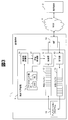
- FIG. 3 is a functional block diagram relating to the data transmission / reception and packet discard rate measurement function 3 in the transmission terminal 1 of the first embodiment of the present invention.
- the transmission terminal includes the NIF 10, the application program 18, and the unique TCP function 3.
- the unique TCP function 3 further includes a transmission unit 11 for transmitting data from the NIF 10 to the WAN 4, a transmission control unit 17 for controlling the amount and order of data transmitted from the transmission unit 11, and data transmitted from the application program 18 temporarily.
- the receiving unit 13 for receiving the data received from the WAN 4 to the NIF 10 and held for re-sending when a packet discard occurs. It consists of a reception buffer 14, a packet count unit 15, and a discard rate calculation unit 16 that confirm the consistency of data order and the like and pass it to the application program 18.
- the number of transmitted packets is counted by the snd counter 20 of the packet count unit.
- Information on the received acknowledgment (Acknowledgement: ACK) and the partial acknowledgment (Selective Acknowledgement: SACK) accompanying the ACK is analyzed by the packet counting unit 15, and the number of packets requested for retransmission (the number of discarded packets). Is counted by the rts counter 21.
- this calculation method is not necessarily an accurate value when the ACK packet is thinned out and transmitted.
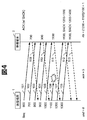
- FIG. 4 is an example of a communication sequence in the first embodiment of the present invention.
- TCP Transmission Control Protocol
- the transmitting terminal 1 transmits a packet with the sequence number “600” (101). Since the receiving terminal 2 has received the packet correctly, it notifies the transmitting terminal 1 of an ACK number “700” as a sequence number to be received next as an acknowledgment (ACK) (109).
- ACK acknowledgment
- the transmitting terminal 1 transmits the packet (102) with the sequence number “700” and the packet (103) with “800” until the ACK is returned, and these are correctly received by the receiving terminal 2.
- the receiving terminal 2 uses Delayed ACK defined in RFC ⁇ 1122, and transmits by decimating ACK. Therefore, ACK is not transmitted even when a packet with sequence number “700” is received, and ACK number “900” is transmitted when a packet with sequence number “800” is received (110).
- the receiving terminal 2 transmits only the ACK number “1000” regarding the packet (104) with the sequence number “900” and the packet (105) with the “1000” (111).
- the receiving terminal 2 transmits a SACK that is a partial confirmation response.
- SACK is information accompanying the ACK and indicates the start and end of a discontinuous portion of the packet held by the receiving terminal 2.
- the SACK block “1200-1300” is notified to the transmitting terminal 1 (112).
- the receiving terminal 1 receives the packet (108) having the sequence number “1300”, the ACK number “1100” SACK block “1200-1400” is notified to the transmitting terminal 1 (113). From this SACK, the transmitting terminal 1 can know a packet discarded in the network and retransmits only that portion.
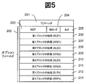
- Fig. 5 shows the SACK packet format.
- the SACK is added to the option field 202 of the TCP header 201.
- a NOP204 (No Operation) 203 indicating that nothing is performed is sandwiched between the type 204 and the length 205, followed by the beginning of the first block (SACK Left Edge: SLE). 206 and the end (SACK Right Edge: SRE) 207 are designated.
- SACK Left Edge: SLE SLE
- SACK Right Edge: SRE SACK Right Edge
- a maximum of 4 blocks can be sent.
- a plurality of packets are discarded, a plurality of SACK blocks are notified.
- the latest four SACK blocks that have been notified in the past are also notified.
- the end of the SACK block increases.
- a subsequent packet is discarded, another SACK block is newly notified in addition to the SACK block.
- This is called a new SACK block.
- the difference between the value at the start of the new SACK block and the closest one of the ACKs notified so far or the end of the SACK block is the number of discarded segments.
- the number of discarded packets is a value obtained by dividing the number of segments by the packet size.
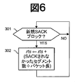
- FIG. 6 is a flowchart of processing in the packet count unit in the first embodiment of the present invention.
- the packet count unit receives a new SACK block (301), it calculates the number of discarded packets by the method described above and counts up rts (302).
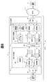
- FIG. 7 is a hardware configuration diagram of the proxy device 5. The difference from the case where the transmission terminal 1 includes the unique TCP function 3 is that a NIF 40 for the LAN 46 is added to connect to the transmission terminal 1. 7 shows an example in which the unique TCP function 3 is entirely configured by software. However, part or all of the unique TCP function 3 may be mounted on the processing device 27 or the NIF 10 and used. .
- Fig. 8 shows a functional block diagram of the proxy device described above.
- the proxy device 5 includes a LAN-side NIF 40, a general TCP function 6 for communicating with the transmitting terminal 1, a NIF 10 connected to the WAN 4, a unique TCP function 3 for communicating with the receiving terminal 2 via the WAN 4, and a unique TCP Also included is a proxy 29 that transfers data between buffers of function 3 and general TCP function 6.
- the packet discard rate is high and a large number of SACK blocks are generated.
- a new SACK block is generated.
- the storage area of the SACK block has a limited capacity, and reaches a limit with a certain number.
- FIG. 9 shows a communication sequence in the second embodiment of the present invention.
- the receiving terminal 2 returns an ACK with a SACK, but all SACK blocks do not change.
- the transmitting terminal 1 has transmitted the packet (121) having the sequence number “600” to the receiving terminal 2, but a large amount of discard has already occurred in the previous packet transmission, and the receiving terminal 2 has received the ACK number “100”.
- the SACK number “400-500,...” Is notified to the transmitting terminal 1.
- the discard storage area of the receiving terminal 2 reaches the limit when the packet (121) having the sequence number “600” is received.
- the receiving terminal 2 notifies the transmitting terminal 1 of the ACK number “100”, the SACK number “600-700, 400-500,...” (128).
- the transmitting terminal 1 transmits a packet with the sequence number “700” (122). This packet is discarded in the network. Further, the transmission terminal 1 transmits a packet with the sequence number “800” (123), which reaches the reception terminal 2.
- a new SACK block is normally generated, but the storage area of the SACK block is limited in capacity, so that the receiving terminal 2 cannot hold a new SACK block, and like the previous ACK packet, The ACK number “100” and the SACK number “600-700, 400-500,...” Are notified to the transmitting terminal 1 (129).
- the same ACK and SACK are returned to the packet (124) with the sequence number “900” (130). Thereafter, it is assumed that packets up to the sequence number “2900” are transmitted and are all discarded at the receiving terminal 2.
- the transmitting terminal 1 retransmits the packet with the sequence number “500” (125).
- “400-500” and “600-700” of the SACK block are connected and become “400-700”, and this is notified (131). Since the number of SACK blocks held by the receiving terminal 2 decreases, a new packet can be received.
- the transmitting terminal 1 transmits a new packet “3000” (126). This is received by the receiving terminal 2 and a new SACK block “3000-3100” is notified (132). The packet (127) with the sequence number “3100” is also correctly received, and the SACK number “3000-3200” is returned (133).
- the snd count section (134) and the rts count section (135) are set for each RTT.
- the calculated value of the discard rate exceeds 1.
- a configuration represented by a functional block diagram as shown in FIG. 10 is adopted.
- the difference from the first embodiment is that the rts counter 21 that counts the number of retransmission requests disappears from the counter of the packet counter 15, the ack counter 22 that counts the number of ACK packets, and the number of ACK packets in which the SACK block information completely overlaps
- the sack.dup counter 23 that counts and the storage unit 24 that stores the SACK block in the previous ACK packet are newly added to the packet count unit 15.
- the storage unit 24 stores the first to fourth block start ends (SLE1 to 4) 30, 32, 34, and 36, and the first to fourth block end points (SRE1 to 4) 31, 33, 35, and 37.
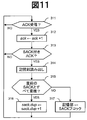
- FIG. 11 is a flowchart of the packet counting unit 15 in the second embodiment of the present invention.
- ack is incremented by 1 (312)
- the previous SACK value received from the storage unit 24 is read (314)
- sack.dup is incremented by 1 (316). Otherwise, the value of the SACK block is recorded in the previous SACK block (317) and the process returns to the top.
- the discard rate calculation unit 16 calculates the discard rate.
- the discard rate is obtained as a value obtained by subtracting 1 from the probability of correct reception.
- Example 2 It was noted in Example 2 that the method of Example 1 is not suitable for high disposal. On the other hand, the method of Example 2 is not suitable for low disposal. This is because, according to RFC 1122, the ACK packet can be transmitted by being thinned out. However, since the method described in the second embodiment obtains the discard rate using the number of ACK packets, it is accurate if the ACK packet is thinned out. This is because the value cannot be obtained.
- FIG. 12 is a flowchart of the discard rate calculation unit 16 in the third embodiment of the present invention.
- the discard rate is calculated for each RTT (401).
- FIG. 1 is a functional block diagram in the third embodiment of the present invention. The difference from the second embodiment is that an rts counter 21 is added to the packet count unit 15.
- FIG. 13 is a flowchart of the packet counting unit 15 in the third embodiment of the present invention. This is a combination of the flowcharts of the first and second embodiments.
- ack is incremented by 1 (312)
- ack is incremented by 1 (313)
- the previous SACK value received from the storage unit 24 is read (314), and the SACK value Is equal to the previously received SACK value (315), sack.dup is incremented by 1 (316). If not, it is determined whether or not it is a new SACK block (301).
- the number of discarded packets is calculated by "number of segments that have not been SACKed, that is, reception has not been confirmed / packet length" Rts is counted up (302).
- the value of the SACK block is recorded in the storage unit 24 (317), and the process returns to the top.
- the storage unit 24 stores the previous SACK block.
- FIG. 15 is a flowchart of the packet counting unit 15 in the fourth embodiment of the present invention.
- the packet count unit 15 determines whether or not the ACK number has advanced (321) every time an ACK is received (311). If not, the packet count unit 15 reads the previous SACK value from the storage unit 24 (314), It is determined whether the starting number in the SACK block is reduced, the terminating number is increased, or whether two or more blocks are connected (322). If there is a change in ACK or SACK, the number of segments is calculated, divided by the packet length, and the number of packets newly received by the receiving terminal 2 is calculated (323). This value is added to ack.real (324). The value of the SACK block is recorded in the storage unit 24 and the process returns to the beginning (317).
- this method since the discard rate can be measured more accurately by a unified method than in the first to third embodiments, this method is effective when the transmission terminal 1 has a sufficient computing capacity.
- FIG. 16 is a functional block diagram of the transmission control unit 17.
- Transmission control in this embodiment is performed by a token bucket algorithm.
- the token bucket algorithm a predetermined amount of tokens are accumulated in the token bucket per unit time, and when this reaches the transmission packet length, the packet can be transmitted.
- the token for the packet length is deducted from the token bucket.
- the transmission control unit 17 includes a token bucket 329 and a timer 330, and also includes a storage unit 332 that stores a value necessary for calculating a token and a token update unit 331 that calculates a token.
- the storage unit includes a loss_ratio storage unit 333 that holds the discard rate calculated by the discard rate calculation unit 16, an old_loss_ratio storage unit 334 that stores a loss_ratio value before the token is updated, and a time that is a reference for the next token update time
- a reference time storage unit 335 that stores the token value, a token storage unit 336 that stores a current token value, an old_token storage unit 337 that stores a token value before the token is updated, and a temporary value when the token value is transferred to old_token Tmp_token storage unit 338 that stores the ACK number, and old_ack_seg storage unit 339 that stores the ACK number before the token is updated.
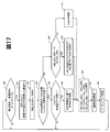
- FIG. 17 is a flowchart showing the operation of the transmission control unit 17.
- the timer 330 determines whether the difference between the current time and the reference time is larger than a predetermined interval (340). A measured RTT or the like may be used as the interval.
- the discard rate acquired from the discard rate calculation unit 16 is stored in loss_ratio (341). Also, the token value is saved in tmp_token (342).
- K times the old_loss_ratio is greater than the loss_ratio with respect to a predetermined constant K of 1 or more (348). If it is larger, the token is reduced based on rts so that it is smaller than old_token. For example, token ⁇ old_token-rts (349). If K times old_loss_ratio is smaller than loss_ratio at 348, token is increased by an arbitrary amount (350).
- loss_ratio is assigned to old_loss_ratio
- tmp_token is assigned to old_token
- the current ACK number is assigned to old_ack_seg (346)
- the reference time is updated (347) and token bucket 329 is updated (348).
Landscapes
- Engineering & Computer Science (AREA)
- Signal Processing (AREA)
- Computer Networks & Wireless Communication (AREA)
- Environmental & Geological Engineering (AREA)
- Multimedia (AREA)
- Quality & Reliability (AREA)
- Data Exchanges In Wide-Area Networks (AREA)
- Detection And Prevention Of Errors In Transmission (AREA)
Priority Applications (1)
| Application Number | Priority Date | Filing Date | Title |
|---|---|---|---|
| US14/650,201 US20150319064A1 (en) | 2013-02-12 | 2013-10-25 | Packet communication method and device |
Applications Claiming Priority (2)
| Application Number | Priority Date | Filing Date | Title |
|---|---|---|---|
| JP2013023999A JP5941853B2 (ja) | 2013-02-12 | 2013-02-12 | パケット通信方法及び装置 |
| JP2013-023999 | 2013-02-12 |
Publications (1)
| Publication Number | Publication Date |
|---|---|
| WO2014125680A1 true WO2014125680A1 (ja) | 2014-08-21 |
Family
ID=51353699
Family Applications (1)
| Application Number | Title | Priority Date | Filing Date |
|---|---|---|---|
| PCT/JP2013/078895 Ceased WO2014125680A1 (ja) | 2013-02-12 | 2013-10-25 | パケット通信方法及び装置 |
Country Status (3)
| Country | Link |
|---|---|
| US (1) | US20150319064A1 (enExample) |
| JP (1) | JP5941853B2 (enExample) |
| WO (1) | WO2014125680A1 (enExample) |
Cited By (1)
| Publication number | Priority date | Publication date | Assignee | Title |
|---|---|---|---|---|
| CN111279644A (zh) * | 2017-10-27 | 2020-06-12 | 瑞典爱立信有限公司 | 用于更新无线网格网络中重传次数的方法和设备 |
Families Citing this family (7)
| Publication number | Priority date | Publication date | Assignee | Title |
|---|---|---|---|---|
| CN104135395B (zh) * | 2014-03-10 | 2015-12-30 | 腾讯科技(深圳)有限公司 | Idc网络中数据传输质量监控方法和系统 |
| US9654483B1 (en) * | 2014-12-23 | 2017-05-16 | Amazon Technologies, Inc. | Network communication rate limiter |
| US11102273B2 (en) * | 2015-05-13 | 2021-08-24 | Cisco Technology, Inc. | Uplink performance management |
| US10396939B2 (en) | 2017-05-22 | 2019-08-27 | Zycada Networks, Inc. | Dynamic management of packet loss |
| US11678332B2 (en) * | 2017-08-22 | 2023-06-13 | Qualcomm Incorporated | Control and data multiplexing in uplink wireless transmissions |
| US11044184B2 (en) * | 2019-05-28 | 2021-06-22 | Servicenow, Inc. | Data packet loss detection |
| US11456938B2 (en) * | 2019-09-25 | 2022-09-27 | Arista Networks, Inc. | Quantifying performance of a connection by monitoring duplicate acknowledgement numbers |
Citations (3)
| Publication number | Priority date | Publication date | Assignee | Title |
|---|---|---|---|---|
| JPH11122296A (ja) * | 1997-10-09 | 1999-04-30 | Chokosoku Network Computer Gijutsu Kenkyusho:Kk | 帯域制御方法 |
| US20070121506A1 (en) * | 2005-05-06 | 2007-05-31 | California Institute Of Technology | Efficient loss recovery architecture for loss-decoupled tcp |
| JP2013132019A (ja) * | 2011-12-22 | 2013-07-04 | Nippon Telegr & Teleph Corp <Ntt> | コンテンツ受信量推定装置及びプログラム |
Family Cites Families (4)
| Publication number | Priority date | Publication date | Assignee | Title |
|---|---|---|---|---|
| JP2005244897A (ja) * | 2004-02-27 | 2005-09-08 | Fujitsu Ltd | 信頼性のある通信方法及びその装置 |
| JP4793652B2 (ja) * | 2004-10-21 | 2011-10-12 | 日本電気株式会社 | 通信品質計測装置及びその計測方法 |
| JP5292444B2 (ja) * | 2011-02-17 | 2013-09-18 | 日本電信電話株式会社 | パケットロス率推定装置及び方法及びプログラム |
| JP5942706B2 (ja) * | 2012-08-29 | 2016-06-29 | 富士通株式会社 | 監視装置,監視プログラム,監視方法 |
-
2013
- 2013-02-12 JP JP2013023999A patent/JP5941853B2/ja not_active Expired - Fee Related
- 2013-10-25 US US14/650,201 patent/US20150319064A1/en not_active Abandoned
- 2013-10-25 WO PCT/JP2013/078895 patent/WO2014125680A1/ja not_active Ceased
Patent Citations (3)
| Publication number | Priority date | Publication date | Assignee | Title |
|---|---|---|---|---|
| JPH11122296A (ja) * | 1997-10-09 | 1999-04-30 | Chokosoku Network Computer Gijutsu Kenkyusho:Kk | 帯域制御方法 |
| US20070121506A1 (en) * | 2005-05-06 | 2007-05-31 | California Institute Of Technology | Efficient loss recovery architecture for loss-decoupled tcp |
| JP2013132019A (ja) * | 2011-12-22 | 2013-07-04 | Nippon Telegr & Teleph Corp <Ntt> | コンテンツ受信量推定装置及びプログラム |
Non-Patent Citations (2)
| Title |
|---|
| KAZUHIRO TAIRA ET AL.: "TCP Proxy Mechanism using TCP-STAR for High-speed Satellite Link", IEICE TECHNICAL REPORT, vol. 107, no. 423, 10 January 2008 (2008-01-10), pages 53 - 58 * |
| MARK ALLMAN ET AL.: "Estimating Loss Rates With TCP", ACM PERFORMANCE EVALUATION REVIEW, Retrieved from the Internet <URL:http://roland.grc.nasa.gov/~weddy/papers/least-per2003.pdf> * |
Cited By (1)
| Publication number | Priority date | Publication date | Assignee | Title |
|---|---|---|---|---|
| CN111279644A (zh) * | 2017-10-27 | 2020-06-12 | 瑞典爱立信有限公司 | 用于更新无线网格网络中重传次数的方法和设备 |
Also Published As
| Publication number | Publication date |
|---|---|
| JP5941853B2 (ja) | 2016-06-29 |
| US20150319064A1 (en) | 2015-11-05 |
| JP2014155080A (ja) | 2014-08-25 |
Similar Documents
| Publication | Publication Date | Title |
|---|---|---|
| JP5941853B2 (ja) | パケット通信方法及び装置 | |
| JP5816718B2 (ja) | 通信装置、通信システム、およびデータ通信の中継方法 | |
| JP4778453B2 (ja) | 通信端末、輻輳制御方法および輻輳制御プログラム | |
| US9843525B2 (en) | Apparatus and method | |
| CN102143078B (zh) | 一种报文处理方法、转发设备及系统 | |
| CN112436924B (zh) | 一种数据传输方法及电子设备 | |
| EP2922241B1 (en) | Methods and apparatus to determine network delay with location independence from retransmission delay and application response time | |
| CN108322401A (zh) | 网络传输拥塞的控制方法及装置 | |
| CN115276916A (zh) | 一种丢弃数据的确定方法、装置、电子设备及存储介质 | |
| KR101039550B1 (ko) | 데이터 전송률 계산 방법 및 이를 이용한 대역폭 설정 방법 | |
| KR20080023176A (ko) | 통신 단말, 통신 제어 방법 및 통신 제어 프로그램 | |
| JP4435817B2 (ja) | 通信端末、通信制御方法および通信制御プログラム | |
| US11153220B2 (en) | Methods and apparatus to determine network delay with location independence | |
| CN118802081B (zh) | 数据重传方法、装置、设备、存储介质以及程序产品 | |
| US20140071993A1 (en) | Transfer device and transfer method | |
| EP3100413B1 (en) | Reliable network probing session | |
| JP2004140596A (ja) | Tcp上のデータ転送における品質を推定する方法およびシステム | |
| JP2009246533A (ja) | 通信端末、通信方法、データ通信システム、およびプログラム | |
| JP2010258631A (ja) | サーバおよびack返信方法 | |
| JP2012134907A (ja) | Tcp転送装置およびそのプログラム | |
| CN119697114A (zh) | 拥塞感知方法、往返时延计算方法和通信设备 | |
| JP2011147035A (ja) | 通信システム、送信装置、受信装置及び通信制御方法 | |
| JP2018152747A (ja) | 設備監視装置 |
Legal Events
| Date | Code | Title | Description |
|---|---|---|---|
| 121 | Ep: the epo has been informed by wipo that ep was designated in this application |
Ref document number: 13874918 Country of ref document: EP Kind code of ref document: A1 |
|
| WWE | Wipo information: entry into national phase |
Ref document number: 14650201 Country of ref document: US |
|
| NENP | Non-entry into the national phase |
Ref country code: DE |
|
| 122 | Ep: pct application non-entry in european phase |
Ref document number: 13874918 Country of ref document: EP Kind code of ref document: A1 |